EP2253417A1 - Processing machine with safety scanner - Google Patents
Processing machine with safety scanner Download PDFInfo
- Publication number
- EP2253417A1 EP2253417A1 EP10162503A EP10162503A EP2253417A1 EP 2253417 A1 EP2253417 A1 EP 2253417A1 EP 10162503 A EP10162503 A EP 10162503A EP 10162503 A EP10162503 A EP 10162503A EP 2253417 A1 EP2253417 A1 EP 2253417A1
- Authority
- EP
- European Patent Office
- Prior art keywords
- sensor
- processing
- area
- processing unit
- processing machine
- Prior art date
- Legal status (The legal status is an assumption and is not a legal conclusion. Google has not performed a legal analysis and makes no representation as to the accuracy of the status listed.)
- Granted
Links
Images

Classifications
-
- B—PERFORMING OPERATIONS; TRANSPORTING
- B23—MACHINE TOOLS; METAL-WORKING NOT OTHERWISE PROVIDED FOR
- B23Q—DETAILS, COMPONENTS, OR ACCESSORIES FOR MACHINE TOOLS, e.g. ARRANGEMENTS FOR COPYING OR CONTROLLING; MACHINE TOOLS IN GENERAL CHARACTERISED BY THE CONSTRUCTION OF PARTICULAR DETAILS OR COMPONENTS; COMBINATIONS OR ASSOCIATIONS OF METAL-WORKING MACHINES, NOT DIRECTED TO A PARTICULAR RESULT
- B23Q1/00—Members which are comprised in the general build-up of a form of machine, particularly relatively large fixed members
- B23Q1/25—Movable or adjustable work or tool supports
- B23Q1/64—Movable or adjustable work or tool supports characterised by the purpose of the movement
- B23Q1/66—Worktables interchangeably movable into operating positions
-
- B—PERFORMING OPERATIONS; TRANSPORTING
- B23—MACHINE TOOLS; METAL-WORKING NOT OTHERWISE PROVIDED FOR
- B23Q—DETAILS, COMPONENTS, OR ACCESSORIES FOR MACHINE TOOLS, e.g. ARRANGEMENTS FOR COPYING OR CONTROLLING; MACHINE TOOLS IN GENERAL CHARACTERISED BY THE CONSTRUCTION OF PARTICULAR DETAILS OR COMPONENTS; COMBINATIONS OR ASSOCIATIONS OF METAL-WORKING MACHINES, NOT DIRECTED TO A PARTICULAR RESULT
- B23Q11/00—Accessories fitted to machine tools for keeping tools or parts of the machine in good working condition or for cooling work; Safety devices specially combined with or arranged in, or specially adapted for use in connection with, machine tools
- B23Q11/0078—Safety devices protecting the operator, e.g. against accident or noise
- B23Q11/0082—Safety devices protecting the operator, e.g. against accident or noise by determining whether the operator is in a dangerous position
-
- B—PERFORMING OPERATIONS; TRANSPORTING
- B23—MACHINE TOOLS; METAL-WORKING NOT OTHERWISE PROVIDED FOR
- B23Q—DETAILS, COMPONENTS, OR ACCESSORIES FOR MACHINE TOOLS, e.g. ARRANGEMENTS FOR COPYING OR CONTROLLING; MACHINE TOOLS IN GENERAL CHARACTERISED BY THE CONSTRUCTION OF PARTICULAR DETAILS OR COMPONENTS; COMBINATIONS OR ASSOCIATIONS OF METAL-WORKING MACHINES, NOT DIRECTED TO A PARTICULAR RESULT
- B23Q11/00—Accessories fitted to machine tools for keeping tools or parts of the machine in good working condition or for cooling work; Safety devices specially combined with or arranged in, or specially adapted for use in connection with, machine tools
- B23Q11/0078—Safety devices protecting the operator, e.g. against accident or noise
- B23Q11/0092—Safety devices protecting the operator, e.g. against accident or noise actuating braking or stopping means
-
- B—PERFORMING OPERATIONS; TRANSPORTING
- B23—MACHINE TOOLS; METAL-WORKING NOT OTHERWISE PROVIDED FOR
- B23Q—DETAILS, COMPONENTS, OR ACCESSORIES FOR MACHINE TOOLS, e.g. ARRANGEMENTS FOR COPYING OR CONTROLLING; MACHINE TOOLS IN GENERAL CHARACTERISED BY THE CONSTRUCTION OF PARTICULAR DETAILS OR COMPONENTS; COMBINATIONS OR ASSOCIATIONS OF METAL-WORKING MACHINES, NOT DIRECTED TO A PARTICULAR RESULT
- B23Q11/00—Accessories fitted to machine tools for keeping tools or parts of the machine in good working condition or for cooling work; Safety devices specially combined with or arranged in, or specially adapted for use in connection with, machine tools
- B23Q11/08—Protective coverings for parts of machine tools; Splash guards
-
- B—PERFORMING OPERATIONS; TRANSPORTING
- B23—MACHINE TOOLS; METAL-WORKING NOT OTHERWISE PROVIDED FOR
- B23Q—DETAILS, COMPONENTS, OR ACCESSORIES FOR MACHINE TOOLS, e.g. ARRANGEMENTS FOR COPYING OR CONTROLLING; MACHINE TOOLS IN GENERAL CHARACTERISED BY THE CONSTRUCTION OF PARTICULAR DETAILS OR COMPONENTS; COMBINATIONS OR ASSOCIATIONS OF METAL-WORKING MACHINES, NOT DIRECTED TO A PARTICULAR RESULT
- B23Q17/00—Arrangements for observing, indicating or measuring on machine tools
- B23Q17/24—Arrangements for observing, indicating or measuring on machine tools using optics or electromagnetic waves
- B23Q17/2404—Arrangements for improving direct observation of the working space, e.g. using mirrors or lamps
-
- B—PERFORMING OPERATIONS; TRANSPORTING
- B23—MACHINE TOOLS; METAL-WORKING NOT OTHERWISE PROVIDED FOR
- B23Q—DETAILS, COMPONENTS, OR ACCESSORIES FOR MACHINE TOOLS, e.g. ARRANGEMENTS FOR COPYING OR CONTROLLING; MACHINE TOOLS IN GENERAL CHARACTERISED BY THE CONSTRUCTION OF PARTICULAR DETAILS OR COMPONENTS; COMBINATIONS OR ASSOCIATIONS OF METAL-WORKING MACHINES, NOT DIRECTED TO A PARTICULAR RESULT
- B23Q17/00—Arrangements for observing, indicating or measuring on machine tools
- B23Q17/24—Arrangements for observing, indicating or measuring on machine tools using optics or electromagnetic waves
- B23Q17/2433—Detection of presence or absence
- B23Q17/2438—Detection of presence or absence of an operator or a part thereof
-
- B—PERFORMING OPERATIONS; TRANSPORTING
- B23—MACHINE TOOLS; METAL-WORKING NOT OTHERWISE PROVIDED FOR
- B23Q—DETAILS, COMPONENTS, OR ACCESSORIES FOR MACHINE TOOLS, e.g. ARRANGEMENTS FOR COPYING OR CONTROLLING; MACHINE TOOLS IN GENERAL CHARACTERISED BY THE CONSTRUCTION OF PARTICULAR DETAILS OR COMPONENTS; COMBINATIONS OR ASSOCIATIONS OF METAL-WORKING MACHINES, NOT DIRECTED TO A PARTICULAR RESULT
- B23Q39/00—Metal-working machines incorporating a plurality of sub-assemblies, each capable of performing a metal-working operation
- B23Q39/02—Metal-working machines incorporating a plurality of sub-assemblies, each capable of performing a metal-working operation the sub-assemblies being capable of being brought to act at a single operating station
- B23Q39/028—Metal-working machines incorporating a plurality of sub-assemblies, each capable of performing a metal-working operation the sub-assemblies being capable of being brought to act at a single operating station with a plurality of workholder per toolhead in operating position
-
- F—MECHANICAL ENGINEERING; LIGHTING; HEATING; WEAPONS; BLASTING
- F16—ENGINEERING ELEMENTS AND UNITS; GENERAL MEASURES FOR PRODUCING AND MAINTAINING EFFECTIVE FUNCTIONING OF MACHINES OR INSTALLATIONS; THERMAL INSULATION IN GENERAL
- F16P—SAFETY DEVICES IN GENERAL; SAFETY DEVICES FOR PRESSES
- F16P3/00—Safety devices acting in conjunction with the control or operation of a machine; Control arrangements requiring the simultaneous use of two or more parts of the body
- F16P3/12—Safety devices acting in conjunction with the control or operation of a machine; Control arrangements requiring the simultaneous use of two or more parts of the body with means, e.g. feelers, which in case of the presence of a body part of a person in or near the danger zone influence the control or operation of the machine
- F16P3/14—Safety devices acting in conjunction with the control or operation of a machine; Control arrangements requiring the simultaneous use of two or more parts of the body with means, e.g. feelers, which in case of the presence of a body part of a person in or near the danger zone influence the control or operation of the machine the means being photocells or other devices sensitive without mechanical contact
- F16P3/141—Safety devices acting in conjunction with the control or operation of a machine; Control arrangements requiring the simultaneous use of two or more parts of the body with means, e.g. feelers, which in case of the presence of a body part of a person in or near the danger zone influence the control or operation of the machine the means being photocells or other devices sensitive without mechanical contact using sound propagation, e.g. sonar
-
- F—MECHANICAL ENGINEERING; LIGHTING; HEATING; WEAPONS; BLASTING
- F16—ENGINEERING ELEMENTS AND UNITS; GENERAL MEASURES FOR PRODUCING AND MAINTAINING EFFECTIVE FUNCTIONING OF MACHINES OR INSTALLATIONS; THERMAL INSULATION IN GENERAL
- F16P—SAFETY DEVICES IN GENERAL; SAFETY DEVICES FOR PRESSES
- F16P3/00—Safety devices acting in conjunction with the control or operation of a machine; Control arrangements requiring the simultaneous use of two or more parts of the body
- F16P3/12—Safety devices acting in conjunction with the control or operation of a machine; Control arrangements requiring the simultaneous use of two or more parts of the body with means, e.g. feelers, which in case of the presence of a body part of a person in or near the danger zone influence the control or operation of the machine
- F16P3/14—Safety devices acting in conjunction with the control or operation of a machine; Control arrangements requiring the simultaneous use of two or more parts of the body with means, e.g. feelers, which in case of the presence of a body part of a person in or near the danger zone influence the control or operation of the machine the means being photocells or other devices sensitive without mechanical contact
- F16P3/142—Safety devices acting in conjunction with the control or operation of a machine; Control arrangements requiring the simultaneous use of two or more parts of the body with means, e.g. feelers, which in case of the presence of a body part of a person in or near the danger zone influence the control or operation of the machine the means being photocells or other devices sensitive without mechanical contact using image capturing devices
-
- F—MECHANICAL ENGINEERING; LIGHTING; HEATING; WEAPONS; BLASTING
- F16—ENGINEERING ELEMENTS AND UNITS; GENERAL MEASURES FOR PRODUCING AND MAINTAINING EFFECTIVE FUNCTIONING OF MACHINES OR INSTALLATIONS; THERMAL INSULATION IN GENERAL
- F16P—SAFETY DEVICES IN GENERAL; SAFETY DEVICES FOR PRESSES
- F16P3/00—Safety devices acting in conjunction with the control or operation of a machine; Control arrangements requiring the simultaneous use of two or more parts of the body
- F16P3/12—Safety devices acting in conjunction with the control or operation of a machine; Control arrangements requiring the simultaneous use of two or more parts of the body with means, e.g. feelers, which in case of the presence of a body part of a person in or near the danger zone influence the control or operation of the machine
- F16P3/14—Safety devices acting in conjunction with the control or operation of a machine; Control arrangements requiring the simultaneous use of two or more parts of the body with means, e.g. feelers, which in case of the presence of a body part of a person in or near the danger zone influence the control or operation of the machine the means being photocells or other devices sensitive without mechanical contact
- F16P3/144—Safety devices acting in conjunction with the control or operation of a machine; Control arrangements requiring the simultaneous use of two or more parts of the body with means, e.g. feelers, which in case of the presence of a body part of a person in or near the danger zone influence the control or operation of the machine the means being photocells or other devices sensitive without mechanical contact using light grids
Definitions
- the invention relates to a processing machine according to the preamble of claim 1 for machining workpieces, which preferably at least partially made of wood, wood materials, wood-like materials, plastic or the like.
- Machining machines of the type mentioned above are widely used in the field of furniture or building supply industry (for example for the manufacture of wooden stairs). In these machines, usually the processing unit, but if necessary also the workpiece clamping unit or both units are designed to be movable.
- the moving machine assemblies can be moved at relatively high speeds. Therefore, especially in CNC-controlled machining centers for woodworking high demands on the safety of the operators are made in order to initiate a particularly inadvertent exceeding the danger limit, the shutdown of the relevant endangered machine part.
- known processing machines have various protective devices, for example a revolving protective fence with a door or the like.
- photoelectric barriers which stop the operation or the movements of the machine units as soon as an object or a person enters the area monitored by the light barrier.
- the DE 10 2007 009 225 B3 discloses a gantry-type machining apparatus in which a Camera head detects a plurality of protection areas, wherein the camera head is arranged on a moving portion of the processing device.
- the design of the camera head has a large blind spot and is designed only to detect protection areas in the immediate vicinity of the processed area, resulting in an unsupervised area.
- this unmonitored area which is arranged in a section accessible to persons of the processing device, sufficient security can not be ensured for persons who are staying at the processing device.
- the invention has for its object to provide a processing machine of the type mentioned, the safety device excludes a hazard to persons as much as possible while ensuring the availability of the machine.
- the movable processing unit can be moved between two dynamic ranges.
- the workpieces can each be processed in one of these two dynamic areas by means of the movable processing unit, while loading and unloading of the workpieces can take place in the second dynamic range.
- the first sensor provided on the movable processing unit which is set up to detect objects, persons, etc., entering into a security area defined in the area of the movable processing unit
- there is also a second sensor which is set up in the second dynamic To capture the area present objects, persons, etc., before the Processing unit is moved in the second dynamic range, wherein the second sensor may have a stationary arranged on the processing machine section.
- the processing machine according to the invention is not limited to the fact that always a pendulum operation is performed. Rather, the processing machine according to the invention can be used for example in so-called single-field occupancy or other modes. This occurs, for example, for larger workpieces. In this case, for example, only a dynamic range is actually used for loading and unloading of workpieces.
- the safety area defined in the area of the movable machine unit moves with the movable machine unit.
- On or in the movable machine unit is also moving along first sensor. When the security area is entered by a person, this is detected by the first sensor.
- the second sensor detects the presence of objects or persons in the second dynamic range, ie in the loading area. If the machining of the workpieces in the first dynamic range, ie in the processing area is completed and the movable machine unit is to move into the loading area, it is first checked by means of the second sensor, whether a person is in the loading area.
- Particularly preferred embodiments of the invention are indicated in the appended claims.
- the processing machine can be designed in particular in gantry design.
- the processing unit can then be moved over a stationary workpiece clamping table.
- the movable processing unit has a safety housing, which encloses the processing unit at least partially. This ensures that an operator can observe the operation of the machine, but can not intervene in hazardous areas such as in the area of processing units.
- the first sensor is provided in the area of thisjeumhausung.
- the first sensor is preferably a contactlessly operating sensor, which can be configured in many different ways in the context of the present invention. Basically, all previously known and still to be developed embodiments can be selected. However, in view of a fast, accurate and interference-free detection, it has proved to be advantageous to use a laser sensor, infrared sensor, ultrasonic sensor, laser triangulation sensor or image acquisition sensor.
- the image capture sensor may be a camera such as a digital camera or CCD camera that assesses the presence of an article based on, for example, a target / actual comparison.
- the first sensor is preferably selected so that it can reliably detect persons in the defined safety area of the machine, even if there are dust or shavings in the area. In previously known systems resulted sometimes the difficulty that the respective sensors also responded to dust or shavings and thereby made an unnecessary shutdown of the processing machine. This should be prevented by appropriate selection of the sensor, which may have a corresponding filter system if possible.
- the processing machine further comprises a cleaning device for the at least one contactless sensor, in particular a blower.
- the second sensor may be, for example, a contact sensor.
- the design of this contact sensor is not particularly limited within the scope of the invention, although pressure switch, pressure switch strips, pull-wire switch and so-called bumpers have proven to be particularly advantageous.
- the second sensor is a non-contact sensor such as a photocell, wherein a transmitter section (first section) is stationary on the processing machine and a receiving section (second section) is movable along the processing unit or a transmitter section is movable on the processing unit and a receiving section is stationary (stationary) are arranged on the processing machine. In this way, it is particularly advantageous possible to accurately detect penetrating or invaded objects or persons in the dynamic areas.
- This control of the two sensors realizes a two-stage safety concept as follows: the first sensor reacts to persons and objects in the safety area, which moves with the movable machine unit. If the first sensor detects a person or an object which could cause a hazard in this safety area, at least the drives of the hazardous machine part are stopped immediately in order to exclude any danger to the person. Unlike in the above-mentioned prior art, the drives are not only slowed down but also switched off.
- the second sensor detects the presence of persons or dangerous objects in the second dynamic range, ie in the loading area.
- the presence of persons and objects in the loading area may well be permissible, as long as the machining of the workpieces in the first dynamic range, ie in the processing area runs. Only when the movable machine unit is to be moved into the loading area in order to machine the workpieces provided there, persons in the loading area can be endangered. In this case, the control on the basis of a corresponding signal of the second sensor, that the movable machine unit can not even be moved into the loading area. Only when the persons have moved away from the loading area, the movable machine unit is released again.
- the invention is further distinguished by a machining method for machining workpieces, in which a processing machine of the type described above is used.
- the method comprises the step of detecting with a second sensor whether there are persons or objects in the second dynamic range before the processing unit is moved to the second dynamic range and the step of slowing down or stopping the processing unit if persons or objects are in the second dynamic range.
- it is particularly advantageously possible to precisely monitor the second dynamic range so that people or objects can advantageously stay in the second dynamic range during processing in the first dynamic range.
- the security is increased.
- the presence of persons and / or objects in the second dynamic range during processing in the first dynamic range is permissible.
- the efficiency of the machining process increases, since it is possible in this way with advantage to manually or automatically introduce workpieces in the second dynamic range or to remove from this.
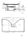
- the processing machine 1 as a preferred embodiment of the present invention is shown in FIGS FIGS. 1 to 3 schematically shown in a front view, top view and side view.
- the processing machine 1 is used in the present embodiment for processing plate-shaped workpieces 2, for example, at least partially made of wood, wood materials or the like, as in Often needed in the furniture or construction supply industry.
- the processing machine 1 has a processing unit 4 which, in the present embodiment, has one in an X direction (from left to right in FIG. 2 ) movable boom 5 has. On the boom 5 at least one processing unit 9 is provided such that it along the boom 5 in a Y-direction and in a Z-direction (perpendicular to plane of FIG. 2 ) is movable.
- the processing unit 9 may for example be designed to perform machining operations on the plate-shaped workpieces 2 or to provide them with an edge. As a rule, several such processing units will be provided, which may for example also be milling, drilling and gluing units.
- a portal or other guide means for the processing unit 9 may be present.
- a tool magazine is provided, by means of which machining tools can be loaded into the processing unit 9.
- the processing machine 1 has a workpiece clamping table 6, which is arranged below the boom 5 in its travel range and is intended to hold the workpieces 2 during processing.
- the workpiece clamping table 6 is arranged stationary in the present embodiment.
- the processing machine 1 is thus realized here in gantry design.
- the workpiece clamping table 6 could also be moved in addition to the boom 5.
- the processing machine 1 is subdivided (at least mentally) into two dynamic areas A and B, in each case alternately loading with workpieces 2 and processing of the workpieces 2 by means of the processing unit 9 can take place (although the invention is not limited to a so-called shuttle operation) ,
- one of the two areas A and B can thus be a processing area, the other a loading area.
- workpieces are provided in the loading area, workpieces are simultaneously machined in the machining area.
- the boom 5 with the processing unit 9 in the left area A, which is currently the processing area.
- the area B which is currently the loading area, in which loading and unloading of workpieces to be machined or finished can take place.
- the boom 5 moves into the current loading area, and the workpieces 2 provided there are processed.
- the loading area becomes the processing area.
- the right area B would be the processing area
- the left area A the loading area from which the finished workpieces would be removed and would be provided in the new green workpieces.
- the workpieces 2 are thus processed in one of the two dynamic areas corresponding to the current processing area A, by means of the processing unit provided on the boom 5, while the processing unit 9 by traversing movements of the boom 5 in the X direction and optionally traversing movements along the boom 5 in the Y and / or Z direction with respect to the workpieces 2 is moved.
- the boom 5 is thereby moved with the highest possible operating speed, which can lead to a risk to persons.
- the processing machine 1 has awhoumhausung 8, which encloses the processing unit 4 and above all ensures that no parts are ejected from the processing machine 1.
- the security housing 8 also holds chips.
- a safety area 12 is defined, which moves with the boom 5.
- the security area extends as it stands out FIG. 2 also results, below and obliquely in front of the free end of the boom 5 and beyond saidraceumhausung 8 addition.
- the security area 12 may extend about 700 or 1000 mm beyond the security enclosure 8.
- the size of the security area can also be based on current or future standards.
- FIG. 4 is a schematic, enlarged view of the security area 12th
- a mitbewegter first contactless operating sensor which is realized in the present embodiment as an optical safety laser scanner 10.
- the first sensor 10 detects during the operation of the processing machine 1, the penetration of objects and people in the security area 12th
- the processing machine 1 has a control device not specifically shown in the drawings, which can be accessed by an operator to control the operation of the machine.
- the control device is also configured to control the operation of the processing machine 1 based on the signals provided by the first sensor 10.
- the controller causes at least the drive of the hazardous machine parts is stopped. In the present case, in particular the traversing movements of the boom 5 and of the processing unit 9 would be stopped and possibly the drive of the processing unit 9 itself.
- the operation of the entire processing machine 1 can be stopped.
- the contactless sensor 10 is, as stated, a laser sensor. As mentioned above, but also different types of sensors can be used.
- blow-off device for the contactless sensor 10 which is intended to clean the sensor when needed.
- the contamination state of the sensor 10 can be monitored in a known per se manner.
- the non-contact sensor 10 continuously performs a monitoring operation of the security area 12.
- second sensors are provided in the processing machine 1 according to the invention, which can detect persons present in the current loading area B.
- the presence of persons in the current loading area B may well be permissible, as long as the processing of the workpieces in the current processing area A expires. Only when the boom 5 is to be moved into the loading area B, present in the loading area B. People at risk. When the boom 5 is to be moved into the loading area B in order to machine the workpieces 2 provided there, the second sensors are therefore used to detect the presence of persons in the loading area.
- these second sensors are realized on the one hand in the form of light barriers.
- the light barriers 14 are in each case formed by a fixed (stationarily) installed transmitter 14 'and a receiver 14 "which is moved together with the boom 5.
- the receivers could also be permanently installed and the transmitters could be moved with the boom 5.
- the corresponding light barrier 14 is activated (whereby the light barrier 14 can possibly also be operated continuously).
- the boom 5 from the position shown in the processing area A should be moved to the right in the loading area B, the provided on the right of the boom 5 photoelectric sensor 14 is activated.
- a corresponding signal of the activated light barrier 14 then causes the boom 5 can not even be moved into the loading area. Only when the persons have moved away from the loading area, the boom 5 is released again.
- the illustrated embodiment has in addition on both sides of the boom 5 bumpers 16, which are moved together with the boom 5 and also detect the presence of people in the loading area B, so also act as second sensors.
- these bumpers 16 are optional and need not necessarily be provided in addition to the light barriers 14.
- the processing machine 1 on three sides (left, right and rear) surrounded by a protective fence 7 or other protective devices, so that the machine 1 is accessible only from the front and must be subjected to safety in this front area , Alternatively, it would also be conceivable to provide electronic protection via corresponding sensors on at least one other side.
Abstract
Description
Die Erfindung betrifft eine Bearbeitungsmaschine nach dem Oberbegriff des Anspruchs 1 zum Bearbeiten von Werkstücken, die bevorzugt zumindest teilweise aus Holz, Holzwerkstoffen, holzähnlichen Stoffen, Kunststoff oder dergleichen bestehen.The invention relates to a processing machine according to the preamble of
Bearbeitungsmaschinen der eingangs genannten Art werden verbreitet im Bereich der Möbel- oder Bauzulieferindustrie (z.B. zur Herstellung von Holztreppen) eingesetzt. Bei diesen Maschinen ist meist die Bearbeitungseinheit, gegebenenfalls aber auch die Werkstückspanneinheit oder beide Einheiten verfahrbar ausgestaltet.Machining machines of the type mentioned above are widely used in the field of furniture or building supply industry (for example for the manufacture of wooden stairs). In these machines, usually the processing unit, but if necessary also the workpiece clamping unit or both units are designed to be movable.
Wegen der hohen Schnittgeschwindigkeiten, die bei der Holzbearbeitung möglich sind, können die beweglichen Maschinen-Baugruppen mit relativ hohen Geschwindigkeiten verfahren werden. Deshalb werden gerade bei CNC-gesteuerten Bearbeitungszentren für die Holzbearbeitung hohe Anforderungen an die Sicherheit der Bedienpersonen gestellt, um bei einem vor allem unbeabsichtigen Überschreiten der Gefahrengrenze das Stillsetzen des betreffenden, gefährdenden Maschinenteils einzuleiten.Because of the high cutting speeds that are possible in woodworking, the moving machine assemblies can be moved at relatively high speeds. Therefore, especially in CNC-controlled machining centers for woodworking high demands on the safety of the operators are made in order to initiate a particularly inadvertent exceeding the danger limit, the shutdown of the relevant endangered machine part.
So weisen bekannte Bearbeitungsmaschinen verschiedene Schutzeinrichtungen auf, beispielsweise einen umlaufenden Schutzzaun mit einer Tür oder dergleichen.For example, known processing machines have various protective devices, for example a revolving protective fence with a door or the like.
Allerdings besteht auch in manchen Situationen die Notwendigkeit, während des Betriebes der Bearbeitungsmaschine an die Maschineneinheiten heranzutreten, beispielsweise um den Bearbeitungsbetrieb zu überwachen.However, in some situations there is a need to approach the machine units during operation of the processing machine, for example to monitor the processing operation.
Vor diesem Hintergrund ist es bekannt, eine oder mehrere Maschineneinheiten mit Kontaktsensoren zu versehen, die den Betrieb oder zumindest die Verfahrbewegungen der Maschineneinheiten anhalten, sobald ein Kontakt mit einem Gegenstand oder einer Person festgestellt wird. Bei derartigen Konstruktionen sind jedoch nur vergleichsweise geringe Arbeitsgeschwindigkeiten von beispielsweise < 40 m/min zugelassen, um beim Aufprall des Kontaktsensors eine Verletzung auszuschließen.Against this background, it is known to provide one or more machine units with contact sensors which stop the operation or at least the traversing movements of the machine units as soon as a contact with an object or a person is detected. In such constructions, however, only comparatively low operating speeds of, for example, <40 m / min are permitted in order to prevent injury upon impact of the contact sensor.
Als Alternative zu Kontaktsensoren sind Lichtschranken bekannt, die den Betrieb oder die Verfahrbewegungen der Maschineneinheiten anhalten, sobald ein Gegenstand oder eine Person in den durch die Lichtschranke überwachten Bereich eindringt.As an alternative to contact sensors, photoelectric barriers are known which stop the operation or the movements of the machine units as soon as an object or a person enters the area monitored by the light barrier.
Aus
Die
Der Erfindung liegt die Aufgabe zugrunde, eine Bearbeitungsmaschine der eingangs genannten Art bereitzustellen, deren Sicherheitseinrichtung eine Gefährdung von Personen so weit wie möglich ausschließt und gleichzeitig die Verfügbarkeit der Maschine gewährleistet.The invention has for its object to provide a processing machine of the type mentioned, the safety device excludes a hazard to persons as much as possible while ensuring the availability of the machine.
Diese Aufgabe wird erfindungsgemäß durch eine Bearbeitungsmaschine mit den Merkmalen des Anspruchs 1 und durch ein Bearbeitungsverfahren mit den Merkmalen des Anspruchs 9 gelöst.This object is achieved by a processing machine having the features of
Demzufolge ist die verfahrbare Bearbeitungseinheit zwischen zwei dynamischen Bereichen verfahrbar. Die Werkstücke können jeweils in einem dieser beiden dynamischen Bereiche mittels der verfahrbaren Bearbeitungseinheit bearbeitet werden, während in dem zweiten dynamischen Bereich ein Be- und Entladen der Werkstücke erfolgen kann. Erfindungsgemäß ist zusätzlich zu dem an der verfahrbaren Bearbeitungseinheit vorgesehenen ersten Sensor, der eingerichtet ist, in einen im Bereich der verfahrbaren Bearbeitungseinheit definierten Sicherheitsbereich eindringende Gegenstände, Personen, etc. zu erfassen, noch ein zweiter Sensor vorhanden, der eingerichtet ist, in dem zweiten dynamischen Bereich anwesende Gegenstände, Personen, etc. zu erfassen, bevor die Bearbeitungseinheit in den zweiten dynamischen Bereich verfahren wird, wobei der zweite Sensor einen stationär an der Bearbeitungsmaschine angeordneten Abschnitt aufweisen kann.As a result, the movable processing unit can be moved between two dynamic ranges. The workpieces can each be processed in one of these two dynamic areas by means of the movable processing unit, while loading and unloading of the workpieces can take place in the second dynamic range. According to the invention, in addition to the first sensor provided on the movable processing unit, which is set up to detect objects, persons, etc., entering into a security area defined in the area of the movable processing unit, there is also a second sensor which is set up in the second dynamic To capture the area present objects, persons, etc., before the Processing unit is moved in the second dynamic range, wherein the second sensor may have a stationary arranged on the processing machine section.
In jedem der beiden dynamischen Bereiche kann daher abwechselnd ein Beladen mit Werkstücken und ein Bearbeiten der Werkstücke stattfinden. Während in einem Bereich zu bearbeitende Werkstücke vorgesehen oder fertig bearbeitete Werkstücke abtransportiert werden können, können gleichzeitig im anderen Bereich Werkstücke bearbeitet werden (sog. Pendelbearbeitung). Dabei ist jedoch zu beachten, dass die erfindungsgemäße Bearbeitungsmaschine nicht darauf beschränkt ist, dass stets ein Pendelbetrieb durchgeführt wird. Vielmehr kann die erfindungsgemäße Bearbeitungsmaschine beispielsweise auch bei sogenannter Einfeldbelegung oder anderen Betriebsarten eingesetzt werden. Dies kommt beispielsweise bei größeren Werkstücken vor. In diesem Falle wird beispielsweise nur ein dynamischer Bereich tatsächlich zum Be- und Entladen von Werkstücken verwendet.In each of the two dynamic areas, therefore, alternately a loading with workpieces and an editing of the workpieces take place. While workpieces to be machined in one area or finished workpieces can be removed, workpieces can be machined simultaneously in the other area (so-called pendulum machining). It should be noted, however, that the processing machine according to the invention is not limited to the fact that always a pendulum operation is performed. Rather, the processing machine according to the invention can be used for example in so-called single-field occupancy or other modes. This occurs, for example, for larger workpieces. In this case, for example, only a dynamic range is actually used for loading and unloading of workpieces.
Der im Bereich der verfahrbaren Maschineneinheit definierte Sicherheitsbereich bewegt sich mit der verfahrbaren Maschineneinheit mit.The safety area defined in the area of the movable machine unit moves with the movable machine unit.
An oder in der verfahrbaren Maschineneinheit befindet sich der ebenfalls mitbewegte erste Sensor. Wenn der Sicherheitsbereich durch eine Person betreten wird, wird dies mittels des ersten Sensors erfasst.On or in the movable machine unit is also moving along first sensor. When the security area is entered by a person, this is detected by the first sensor.
Der zweite Sensor erfasst die Anwesenheit von Gegenständen oder Personen im zweiten dynamischen Bereich, d.h. im Beladebereich. Wenn die Bearbeitung der Werkstücke im ersten dynamischen Bereich, d.h. im Bearbeitungsbereich beendet ist und die verfahrbare Maschineneinheit in den Beladebereich einfahren soll, wird zunächst mittels des zweiten Sensors überprüft, ob sich eine Person in dem Beladebereich befindet. Besonders bevorzugte Ausführungsformen der Erfindung sind in den anhängigen Ansprüchen angegeben.The second sensor detects the presence of objects or persons in the second dynamic range, ie in the loading area. If the machining of the workpieces in the first dynamic range, ie in the processing area is completed and the movable machine unit is to move into the loading area, it is first checked by means of the second sensor, whether a person is in the loading area. Particularly preferred embodiments of the invention are indicated in the appended claims.
Die Bearbeitungsmaschine kann insbesondere in Gantry-Bauweise ausgestaltet sein. Die Bearbeitungseinheit ist dann über einem stationären Werkstückspanntisch verfahrbar.The processing machine can be designed in particular in gantry design. The processing unit can then be moved over a stationary workpiece clamping table.
Um das Sicherheitsniveau weiter zu erhöhen, ist gemäß einer Weiterbildung der Erfindung vorgesehen, dass die verfahrbare Bearbeitungseinheit eine Sicherheitsumhausung aufweist, welche die Bearbeitungseinheit zumindest teilweise umschließt. Auf diese Weise wird sichergestellt, dass eine Bedienperson den Betrieb der Maschine beobachten, jedoch nicht in gefährliche Bereiche wie beispielsweise in den Bereich von Bearbeitungsaggregaten eingreifen kann. Dabei ist der erste Sensor im Bereich dieser Sicherheitsumhausung vorgesehen.In order to further increase the level of security, it is provided according to a development of the invention that the movable processing unit has a safety housing, which encloses the processing unit at least partially. This ensures that an operator can observe the operation of the machine, but can not intervene in hazardous areas such as in the area of processing units. In this case, the first sensor is provided in the area of this Sicherheitsumhausung.
Der erste Sensor ist vorzugsweise ein kontaktlos arbeitender Sensor, der im Rahmen der vorliegenden Erfindung auf unterschiedlichste Art und Weise ausgestaltet sein kann. Es können im Grunde alle bisher bekannten und noch zu entwickelnden Ausgestaltungen gewählt werden. Im Hinblick auf eine schnelle, präzise und störungsfreie Erfassung hatte sich jedoch als vorteilhaft erwiesen, dass ein Lasersensor, Infrarotsensor, Ultraschallsensor, Lasertriangulationssensor oder Bilderfassungssensor gewählt wird. Bei dem Bilderfassungssensor kann es sich beispielsweise um eine Kamera wie eine Digitalkamera oder CCD-Kamera handeln, welche die Anwesenheit eines Gegenstands beispielsweise auf der Grundlage eines Soll-/Ist-Vergleichs beurteilt.The first sensor is preferably a contactlessly operating sensor, which can be configured in many different ways in the context of the present invention. Basically, all previously known and still to be developed embodiments can be selected. However, in view of a fast, accurate and interference-free detection, it has proved to be advantageous to use a laser sensor, infrared sensor, ultrasonic sensor, laser triangulation sensor or image acquisition sensor. For example, the image capture sensor may be a camera such as a digital camera or CCD camera that assesses the presence of an article based on, for example, a target / actual comparison.
Der erste Sensor wird dabei vorzugsweise so ausgewählt, dass er Personen im definierten Sicherheitsbereich der Maschine sicher erkennen kann, auch wenn sich im Bereich Staub oder Späne befinden. Bei bisher bekannten Systemen ergab sich mitunter die Schwierigkeit, dass die jeweiligen Sensoren auch auf Staub oder Späne ansprachen und dadurch ein unnötiges Abschalten der Bearbeitungsmaschine erfolgte. Dies sollte durch geeignete Auswahl des Sensors, der ggf. über einen entsprechendes Filtersystem verfügt, nach Möglichkeit verhindert werden.The first sensor is preferably selected so that it can reliably detect persons in the defined safety area of the machine, even if there are dust or shavings in the area. In previously known systems resulted sometimes the difficulty that the respective sensors also responded to dust or shavings and thereby made an unnecessary shutdown of the processing machine. This should be prevented by appropriate selection of the sensor, which may have a corresponding filter system if possible.
Um auch im Umfeld schmutzbehafteter Bearbeitungen wie beispielsweise spanender Bearbeitungen einen zuverlässigen Betrieb des mindestens einen kontaktlos arbeitenden Sensors sicherzustellen, ist gemäß einer Weiterbildung der Erfindung vorgesehen, dass die Bearbeitungsmaschine ferner eine Reinigungseinrichtung für den mindestens einen kontaktlos arbeitenden Sensor aufweist, insbesondere eine Abblaseinrichtung.In order to ensure reliable operation of the at least one contactless operating sensor even in the environment of dirty machining operations such as machining operations, it is provided according to a development of the invention that the processing machine further comprises a cleaning device for the at least one contactless sensor, in particular a blower.
Der zweite Sensor kann beispielsweise ein Kontaktsensor sein. Die Ausgestaltung dieses Kontaktsensors ist im Rahmen der Erfindung nicht besonders beschränkt, obgleich sich Druckschalter, Druckschalterleisten, Seilzugschalter und so genannte Bumper als besonders vorteilhaft erwiesen haben. Vorzugsweise ist der zweite Sensor aber ein berührungsloser Sensor wie beispielsweise eine Lichtschranke, wobei ein Senderabschnitt (erster Abschnitt) stationär an der Bearbeitungsmaschine und ein Empfangsabschnitt (zweiter Abschnitt) mitbewegbar an der Bearbeitungseinheit oder ein Senderabschnitt mitbewegbar an der Bearbeitungseinheit und ein Empfangsabschnitt stationär (ortsfest) an der Bearbeitungsmaschine angeordnet sind. Auf diese Weise ist es besonders vorteilhaft möglich, in die dynamischen Bereiche eindringende bzw. eingedrungene Gegenstände oder Personen exakt zu erfassen.The second sensor may be, for example, a contact sensor. The design of this contact sensor is not particularly limited within the scope of the invention, although pressure switch, pressure switch strips, pull-wire switch and so-called bumpers have proven to be particularly advantageous. Preferably, however, the second sensor is a non-contact sensor such as a photocell, wherein a transmitter section (first section) is stationary on the processing machine and a receiving section (second section) is movable along the processing unit or a transmitter section is movable on the processing unit and a receiving section is stationary (stationary) are arranged on the processing machine. In this way, it is particularly advantageous possible to accurately detect penetrating or invaded objects or persons in the dynamic areas.
Gemäß einer Weiterbildung der Erfindung besitzt die Bearbeitungsmaschine ferner eine Steuereinrichtung, die eingerichtet ist, den Betrieb zumindest eines Teils der Bearbeitungsmaschine anzuhalten und/oder das weitere Verfahren der verfahrbaren Bearbeitungseinheit zu verhindern, wenn
- der erste Sensor einen Gegenstand oder eine Person in dem Sicherheitsbereich erfasst, oder
- die verfahrbare Bearbeitungseinheit in den Beladebereich verfahren werden soll und der zweite Sensor einen Gegenstand oder eine Person in dem Beladebereich erfasst.
- the first sensor detects an object or a person in the security area, or
- the movable processing unit is to be moved into the loading area and the second sensor detects an object or a person in the loading area.
Durch diese Steuerung der beiden Sensoren wird wie folgt ein zweistufiges Sicherheitskonzept realisiert: der erste Sensor reagiert auf Personen und Gegenstände im Sicherheitsbereich, der sich mit der verfahrbaren Maschineneinheit mitbewegt. Wenn der erste Sensor eine Person oder einen Gegenstand, der eine Gefährdung bewirken könnte, in diesem Sicherheitsbereich erkennt, werden zumindest die Antriebe des gefährdenden Maschinenteils unmittelbar angehalten, um eine Gefährdung der Person auszuschließen. Anders als im oben genannten Stand der Technik werden die Antriebe dabei nicht nur verlangsamt, sondern auch abgeschaltet.This control of the two sensors realizes a two-stage safety concept as follows: the first sensor reacts to persons and objects in the safety area, which moves with the movable machine unit. If the first sensor detects a person or an object which could cause a hazard in this safety area, at least the drives of the hazardous machine part are stopped immediately in order to exclude any danger to the person. Unlike in the above-mentioned prior art, the drives are not only slowed down but also switched off.
Der zweite Sensor erfasst dagegen die Anwesenheit von Personen oder gefährdenden Gegenständen im zweiten dynamischen Bereich, d.h. im Beladebereich. Dabei kann die Anwesenheit von Personen und Gegenständen im Beladebereich durchaus zulässig sein, solange die Bearbeitung der Werkstücke im ersten dynamischen Bereich, d.h. im Bearbeitungsbereich abläuft. Erst wenn die verfahrbare Maschineneinheit in den Beladebereich verfahren werden soll, um die dort vorgesehenen Werkstücke zu bearbeiten, können Personen im Beladebereich gefährdet sein. In diesem Fall bewirkt die Steuerung auf der Grundlage eines entsprechenden Signals des zweiten Sensors, dass die verfahrbare Maschineneinheit erst gar nicht in den Beladebereich verfahren werden kann. Erst wenn sich die Personen aus dem Beladebereich entfernt haben, wird die verfahrbare Maschineneinheit wieder freigegeben.By contrast, the second sensor detects the presence of persons or dangerous objects in the second dynamic range, ie in the loading area. The presence of persons and objects in the loading area may well be permissible, as long as the machining of the workpieces in the first dynamic range, ie in the processing area runs. Only when the movable machine unit is to be moved into the loading area in order to machine the workpieces provided there, persons in the loading area can be endangered. In this case, the control on the basis of a corresponding signal of the second sensor, that the movable machine unit can not even be moved into the loading area. Only when the persons have moved away from the loading area, the movable machine unit is released again.
Die Erfindung zeichnet sich ferner durch ein Bearbeitungsverfahren zum Bearbeiten von Werkstücken aus, bei welchem eine Bearbeitungsmaschine der vorher beschriebenen Art zum Einsatz kommt. Das Verfahren umfasst dabei den Schritt des Erfassens mit einem zweiten Sensor, ob sich in dem zweiten dynamischen Bereich Personen oder Gegenstände befinden, bevor die Bearbeitungseinheit in den zweiten dynamischen Bereich verfahren wird und den Schritt des Verlangsamens bzw. des Anhaltens der Bearbeitungseinheit, falls sich Personen oder Gegenstände in dem zweiten dynamischen Bereich befinden. Auf diese Weise ist es besonders vorteilhaft möglich, den zweiten dynamischen Bereich exakt zu überwachen, so dass sich Personen bzw. Gegenstände während einer Bearbeitung in dem ersten dynamischen Bereich mit Vorteil in dem zweiten dynamischen Bereich aufhalten können. Auf diese Weise ist es beispielsweise möglich, den zweiten dynamischen Bereich mit zu bearbeitenden Werkstücken zu versehen, diese zu entnehmen und/oder Wartungstätigkeiten oder dergleichen dort durchzuführen. Ferner wird durch das Verlangsamen bzw. Anhalten der Bearbeitungseinheit, falls sich Personen oder Gegenstände in dem zweiten dynamischen Bereich befinden, die Sicherheit erhöht.The invention is further distinguished by a machining method for machining workpieces, in which a processing machine of the type described above is used. The method comprises the step of detecting with a second sensor whether there are persons or objects in the second dynamic range before the processing unit is moved to the second dynamic range and the step of slowing down or stopping the processing unit if persons or objects are in the second dynamic range. In this way, it is particularly advantageously possible to precisely monitor the second dynamic range so that people or objects can advantageously stay in the second dynamic range during processing in the first dynamic range. In this way, it is possible, for example, to provide the second dynamic range with workpieces to be machined, remove them and / or perform maintenance activities or the like there. Further, by slowing down the processing unit, if there are persons or objects in the second dynamic area, the security is increased.
Gemäß einer bevorzugten Weiterbildung des Verfahrens ist die Anwesenheit von Personen und/oder Gegenständen in dem zweiten dynamischen Bereich während der Bearbeitung in dem ersten dynamischen Bereich zulässig. Auf diese Weise erhöht sich die Effizienz des Bearbeitungsverfahrens, da es auf diese Weise mit Vorteil möglich ist, manuell oder automatisch Werkstücke in den zweiten dynamischen Bereich einzubringen oder aus diesem zu entnehmen.According to a preferred development of the method, the presence of persons and / or objects in the second dynamic range during processing in the first dynamic range is permissible. In this way, the efficiency of the machining process increases, since it is possible in this way with advantage to manually or automatically introduce workpieces in the second dynamic range or to remove from this.
Gemäß einer weiteren Ausführungsform des Verfahrens wird, sobald sich die Person bzw. der Gegenstand, die sich nach dem Verlagsamen bzw. dem Anhalten in dem zweiten dynamischen Bereich aufhalten, entfernt haben, die Bearbeitungseinheit zum Bearbeiten in den zweiten dynamischen Bereich verfahren und eine Bearbeitung durchgeführt. Auf diese Weise ist es besonders vorteilhaft möglich, unmittelbar nachdem der "Sicherheitsbereich" (also der zweite dynamische Bereich) geräumt wurde, eine Bearbeitung wieder durchzuführen bzw. erneut aufzunehmen.According to a further embodiment of the method, as soon as the person or the object, which after the Verlagsamen or stopping in the second dynamic Stop the area, remove it, move the processing unit to the second dynamic area for processing and carry out a processing. In this way, it is particularly advantageous possible immediately after the "security area" (ie, the second dynamic range) has been vacated to perform a processing again or resume.
-
Figur 1 zeigt schematisch eine Frontansicht einer erfindungsgemäßen Bearbeitungsmaschine;FIG. 1 shows a schematic front view of a processing machine according to the invention; -
Figur 2 zeigt schematisch eine Draufsicht der inFigur 1 gezeigten Bearbeitungsmaschine;FIG. 2 schematically shows a plan view of inFIG. 1 shown processing machine; -
Figur 3 zeigt schematisch eine Seitenansicht der inFigur 1 gezeigten Bearbeitungsmaschine; undFIG. 3 schematically shows a side view of inFIG. 1 shown processing machine; and -
Figur 4 ist eine schematische, vergrößerte Darstellung eines Sicherheitsbereichs der inFigur 1 gezeigten Bearbeitungsmaschine.FIG. 4 is a schematic, enlarged view of a security range of inFIG. 1 shown processing machine.
Ausführliche Beschreibung bevorzugter AusführungsformenDetailed description of preferred embodiments
Bevorzugte Ausführungsformen der Erfindung werden nachfolgend ausführlich in Bezugnahme auf die begleitenden Zeichnungen beschrieben.Preferred embodiments of the invention will now be described in detail with reference to the accompanying drawings.
Die Bearbeitungsmaschine 1 als bevorzugte Ausführungsform der vorliegenden Erfindung ist in den
Die Bearbeitungsmaschine 1 besitzt eine Bearbeitungseinheit 4, die in der vorliegenden Ausführungsform einen in einer X-Richtung (von links nach rechts in
Es sei darauf hingewiesen, dass anstelle des Auslegers 5 beispielsweise auch ein Portal oder eine andere Führungseinrichtung für das Bearbeitungsaggregat 9 vorhanden sein kann.It should be noted that instead of the
Am hinteren Ende des Auslegers 5 ist ein Werkzeugmagazin vorgesehen, mittels dessen Bearbeitungswerkzeuge in das Bearbeitungsaggregat 9 eingewechselt werden können.At the rear end of the
Ferner besitzt die Bearbeitungsmaschine 1 einen Werkstückspanntisch 6, der unterhalb des Auslegers 5 in dessen Verfahrbereich angeordnet und dazu vorgesehen ist, die Werkstücke 2 während der Bearbeitung zu halten. Der Werkstückspanntisch 6 ist in der vorliegenden Ausführungsform stationär angeordnet. Die Bearbeitungsmaschine 1 ist hier somit in Gantry-Bauweise realisiert. Alternativ könnte der Werkstückspanntisch 6 zusätzlich zu dem Ausleger 5 ebenfalls verfahrbar sein.Further, the
Die Bearbeitungsmaschine 1 ist (zumindest gedanklich) in zwei dynamische Bereiche A und B unterteilt, in denen jeweils abwechselnd ein Beladen mit Werkstücken 2 und ein Bearbeiten der Werkstücke 2 mittels des Bearbeitungsaggregats 9 stattfinden kann (obgleich die Erfindung nicht auf einen sogenannten Pendelbetrieb beschränkt ist). Im Wechsel kann somit einer der beiden Bereiche A und B ein Bearbeitungsbereich, der andere ein Beladebereich sein. Während im Beladebereich Werkstücke vorgesehen werden, werden gleichzeitig im Bearbeitungsbereich Werkstücke bearbeitet. In der Darstellung der
Sobald die Bearbeitung der Werkstücke 2 in dem momentanen Bearbeitungsbereich abgeschlossen ist, verfährt der Ausleger 5 in den momentanen Beladebereich, und die dort vorgesehenen Werkstücke 2 werden bearbeitet. Der Beladebereich wird so zum Bearbeitungsbereich. In der Darstellung der
Während des Betriebes der Bearbeitungsmaschine 1 werden die Werkstücke 2 somit in einem der beiden dynamischen Bereiche, der dem momentanen Bearbeitungsbereich A entspricht, mittels des am Ausleger 5 vorgesehenen Bearbeitungsaggregats bearbeitet, während das Bearbeitungsaggregat 9 durch Verfahrbewegungen des Auslegers 5 in X-Richtung und gegebenenfalls Verfahrbewegungen entlang des Auslegers 5 in Y- und/oder Z-Richtung in Bezug auf die Werkstücke 2 verfahren wird. Um die Bearbeitungszeit möglichst kurz zu halten, wird der Ausleger 5 dabei mit einer möglichst hohen Betriebsgeschwindigkeit verfahren, was zu einer Gefährdung von Personen führen kann.During operation of the
Ferner besitzt die Bearbeitungsmaschine 1 eine Sicherheitsumhausung 8, welche die Bearbeitungseinheit 4 umschließt und vor allem dafür sorgt, dass keine Teile aus der Bearbeitungsmaschine 1 herausgeschleudert werden. Darüber hinaus hält die Sicherheitsumhausung 8 auch Späne zurück.Furthermore, the
Im Bereich der verfahrbaren Maschineneinheit 4 ist ein Sicherheitsbereich 12 definiert, der sich mit dem Ausleger 5 mitbewegt. Der Sicherheitsbereich erstreckt sich dabei, wie sich aus
An oder in der verfahrbaren Maschineneinheit 4 befindet sich ein ebenfalls mitbewegter erster, kontaktlos arbeitender Sensor, der in der vorliegenden Ausführungsform als optischer Sicherheitslaserscanner 10 realisiert ist. Der erste Sensor 10 erfasst während des Betriebs der Bearbeitungsmaschine 1 das Eindringen von Gegenständen und Personen in den Sicherheitsbereich 12.On or in the movable machine unit 4 is also a mitbewegter first contactless operating sensor, which is realized in the present embodiment as an optical
Die Bearbeitungsmaschine 1 weist schließlich eine in den Zeichnungen nicht eigens gezeigte Steuereinrichtung auf, auf die eine Bedienperson zugreifen kann, um den Betrieb der Maschine zu steuern. Dabei ist die Steuereinrichtung auch dazu eingerichtet, den Betrieb der Bearbeitungsmaschine 1 auf der Grundlage der vom ersten Sensor 10 gelieferten Signale zu steuern. Wenn der Sicherheitsbereich 12 durch eine Person betreten wird, wird dies mittels des ersten Sensors 10 erfasst. Die Steuerung bewirkt dann, dass zumindest der Antrieb der gefährdenden Maschinenteile angehalten wird. Im vorliegenden Fall würden insbesondere die Verfahrbewegungen des Auslegers 5 und des Bearbeitungsaggregats 9 gestoppt sowie ggf. der Antrieb der Bearbeitungsaggregats 9 selbst. Gegebenenfalls kann auch der Betrieb der gesamten Bearbeitungsmaschine 1 gestoppt werden.Finally, the
Bei dem kontaktlos arbeitenden Sensor 10 handelt es sich in der vorliegenden Ausführungsform wie gesagt um einen Lasersensor. Wie oben bereits erwähnt, können aber auch andersartige Sensoren zum Einsatz kommen.In the present embodiment, the
In den Figuren nicht gezeigt ist eine in der vorliegenden Ausführungsform ebenfalls vorgesehene Abblaseinrichtung für den kontaktlos arbeitenden Sensor 10, die dazu vorgesehen ist, den Sensor bei Bedarf zu reinigen. Der Verschmutzungszustand des Sensors 10 kann dabei auf an sich bekannte Art und Weise überwacht werden.Not shown in the figures is also provided in the present embodiment blow-off device for the
Während des Betriebs der Bearbeitungsmaschine 1 führt der kontaktlos arbeitende Sensor 10 kontinuierlich einen Überwachungsbetrieb des Sicherheitsbereichs 12 aus.During operation of the
Zusätzlich sind in der erfindungsgemäßen Bearbeitungsmaschine 1 zweite Sensoren vorgesehen, die in dem momentanen Beladebereich B anwesende Personen erfassen können.In addition, second sensors are provided in the
Dabei kann die Anwesenheit von Personen im momentanen Beladebereich B durchaus zulässig sein, solange die Bearbeitung der Werkstücke im momentanen Bearbeitungsbereich A abläuft. Erst wenn der Ausleger 5 in den Beladebereich B verfahren werden soll, können im Beladebereich B anwesende Personen gefährdet sein. Wenn der Ausleger 5 in den Beladebereich B verfahren werden soll, um die dort vorgesehenen Werkstücke 2 zu bearbeiten, werden daher die zweiten Sensoren herangezogen, um die Anwesenheit von Personen im Beladebereich zu erfassen.The presence of persons in the current loading area B may well be permissible, as long as the processing of the workpieces in the current processing area A expires. Only when the
In der vorliegenden Ausführungsform sind diese zweiten Sensoren einerseits in Form von Lichtschranken realisiert. Die Lichtschranken 14 werden jeweils von einem fest (stationär) installierten Sender 14' und einem mit dem Ausleger 5 mitbewegten Empfänger 14" gebildet. Alternativ könnten natürlich auch die Empfänger fest installiert sein und die Sender mit dem Ausleger 5 mitbewegt werden.In the present embodiment, these second sensors are realized on the one hand in the form of light barriers. The
Soll der Ausleger 5 in den momentanen Beladebereich B verfahren werden, so wird die entsprechende Lichtschranke 14 aktiviert (wobei die Lichtschranke 14 ggf. auch kontinuierlich betrieben werden kann). In der Darstellung gemäß
Die dargestellte Ausführungsform weist zusätzlich beiderseits des Auslegers 5 Bumper 16 auf, die mit dem Ausleger 5 zusammen verfahren werden und ebenfalls die Anwesenheit von Personen im Beladebereich B erfassen, also ebenfalls als zweite Sensoren fungieren. Diese Bumper 16 sind aber optional und müssen nicht unbedingt zusätzlich zu den Lichtschranken 14 vorgesehen sein.The illustrated embodiment has in addition on both sides of the
Wie in
Claims (11)
mit mindestens einer verfahrbaren
Bearbeitungseinheit (4), die einen ersten Sensor (10) aufweist, der eingerichtet ist, in einen im Bereich der verfahrbaren Bearbeitungseinheit (4) definierten Sicherheitsbereich (12) eindringende Gegenstände und Personen zu erfassen,
dadurch gekennzeichnet, dass
die verfahrbare Bearbeitungseinheit (4) zwischen zwei dynamischen Bereichen (A, B) verfahrbar ist und die Werkstücke (2) jeweils in einem (A) dieser beiden dynamischen Bereiche mittels der verfahrbaren Bearbeitungseinheit (4) bearbeitet werden können, während in dem zweiten (B) dynamischen Bereich ein Be- und Entladen der Werkstücke (2) erfolgen kann, und
die Bearbeitungsmaschine ferner einen zweiten Sensor (14) aufweist, der eingerichtet ist, in dem zweiten dynamischen Bereich (B) anwesende Gegenstände und Personen zu erfassen, bevor die Bearbeitungseinheit (4) in den zweiten dynamischen Bereich (B) verfahren wird.Processing machine (1) for machining workpieces (2), which are preferably at least partially made of wood, wood-based materials, wood-like materials, plastic or the like,
with at least one movable one
Processing unit (4), which has a first sensor (10) which is set up to detect objects and persons entering a safety area (12) defined in the area of the movable processing unit (4),
characterized in that
the movable machining unit (4) is movable between two dynamic areas (A, B) and the workpieces (2) can each be machined in one (A) of these two dynamic areas by means of the movable machining unit (4), while in the second (B ) dynamic loading and unloading of the workpieces (2) can take place, and
the processing machine further comprises a second sensor (14) arranged to detect objects and persons present in the second dynamic area (B) before the processing unit (4) is moved to the second dynamic area (B).
unter Einsatz einer Bearbeitungsmaschine nach einem der vorhergehenden Ansprüche,
wobei das Bearbeitungsverfahren die folgenden Schritte umfasst:
using a processing machine according to one of the preceding claims,
the processing method comprising the steps of:
Priority Applications (1)
| Application Number | Priority Date | Filing Date | Title |
|---|---|---|---|
| PL10162503T PL2253417T3 (en) | 2009-05-15 | 2010-05-11 | Processing machine with safety scanner |
Applications Claiming Priority (1)
| Application Number | Priority Date | Filing Date | Title |
|---|---|---|---|
| DE202009007035U DE202009007035U1 (en) | 2009-05-15 | 2009-05-15 | Processing machine with security scanner |
Publications (2)
| Publication Number | Publication Date |
|---|---|
| EP2253417A1 true EP2253417A1 (en) | 2010-11-24 |
| EP2253417B1 EP2253417B1 (en) | 2011-07-20 |
Family
ID=42342486
Family Applications (1)
| Application Number | Title | Priority Date | Filing Date |
|---|---|---|---|
| EP10162503A Active EP2253417B1 (en) | 2009-05-15 | 2010-05-11 | Processing machine with safety scanner |
Country Status (5)
| Country | Link |
|---|---|
| EP (1) | EP2253417B1 (en) |
| AT (1) | ATE516916T1 (en) |
| DE (1) | DE202009007035U1 (en) |
| ES (1) | ES2367958T3 (en) |
| PL (1) | PL2253417T3 (en) |
Cited By (6)
| Publication number | Priority date | Publication date | Assignee | Title |
|---|---|---|---|---|
| EP2713093A2 (en) | 2012-09-28 | 2014-04-02 | Homag Holzbearbeitungssysteme GmbH | Bumper with integrated sensor |
| CN106470797A (en) * | 2014-06-04 | 2017-03-01 | 霍尔兹玛面板分割科技有限公司 | Method for running plate processing unit (plant) and plate processing unit (plant) |
| ITUB20153815A1 (en) * | 2015-09-22 | 2017-03-22 | F O M Ind S R L | MACHINE FOR PROCESSING ALUMINUM COMPONENTS, LIGHT ALLOYS, OR SIMILAR |
| EP3422053A1 (en) | 2017-06-28 | 2019-01-02 | Datalogic IP Tech S.r.l. | Safety system |
| IT201800001134A1 (en) * | 2018-01-17 | 2019-07-17 | Scm Group Spa | Machine for processing wooden pieces and the like, equipped with a safety system for detecting the presence of an operator and relative operating method. |
| EP3915721B1 (en) | 2020-05-29 | 2022-12-28 | C.M.S. S.p.A. | Machine for the processing of parts in a pendular cycle |
Families Citing this family (11)
| Publication number | Priority date | Publication date | Assignee | Title |
|---|---|---|---|---|
| DE102011007517A1 (en) * | 2011-04-15 | 2012-10-18 | Homag Holzbearbeitungssysteme Gmbh | processing machine |
| ITBO20110626A1 (en) * | 2011-11-04 | 2013-05-05 | Biesse Spa | MACHINE FOR PROCESSING WOOD OR SIMILAR COMPONENTS |
| ITMO20120033A1 (en) * | 2012-02-15 | 2013-08-16 | Scm Group Spa | PROCESSING APPARATUS |
| DE102014115027A1 (en) * | 2014-10-16 | 2016-04-21 | epis Automation GmbH & Co. KG | Cutting device and cutting method |
| ITUB20159437A1 (en) * | 2015-12-16 | 2017-06-16 | Scm Group Spa | Processing apparatus |
| DE102015226299A1 (en) | 2015-12-21 | 2017-06-22 | Weeke Bohrsysteme Gmbh | processing device |
| ITUA20163674A1 (en) * | 2016-05-23 | 2017-11-23 | Scm Group Spa | WORK CENTER |
| IT201700052883A1 (en) * | 2017-05-16 | 2018-11-16 | Biesse Spa | MACHINE FOR PROCESSING WOOD OR SIMILAR COMPONENTS |
| WO2020005080A1 (en) * | 2018-06-29 | 2020-01-02 | Turinsky Wilfried Manfred | A safety device for use with a panel return and an edgebander |
| IT202000019618A1 (en) * | 2020-08-07 | 2022-02-07 | Scm Group Spa | MACHINE WITH SAFETY SYSTEM. |
| DE102022107819A1 (en) | 2022-04-01 | 2023-10-05 | Homag Gmbh | Device for processing a workpiece |
Citations (3)
| Publication number | Priority date | Publication date | Assignee | Title |
|---|---|---|---|---|
| FR2478514A1 (en) * | 1980-03-20 | 1981-09-25 | Aeg Elotherm Gmbh | Machine tool operator protection equipment - reflects transmitter waves from working surface to receiver controlling safety switch |
| DE102006052017A1 (en) * | 2006-11-03 | 2008-05-08 | Homag Holzbearbeitungssysteme Ag | processing machine |
| DE102007009225B3 (en) | 2007-02-26 | 2008-07-03 | Sick Ag | Machine tool for machining workpieces, has device for supporting machining workpieces and movably dangerous machining element for machining workpieces, which are carried by movable holder |
Family Cites Families (3)
| Publication number | Priority date | Publication date | Assignee | Title |
|---|---|---|---|---|
| US5047752A (en) * | 1989-11-14 | 1991-09-10 | Murata Wiedemann, Inc. | Safety system for a machine tool |
| DE10039970B4 (en) * | 2000-08-16 | 2007-06-21 | Homag Maschinenbau Ag | Machining center and method for processing multiple workpieces |
| WO2008071805A1 (en) * | 2006-12-15 | 2008-06-19 | Fachhochschule Bonn-Rhein-Sieg | A manually fed machine for working on materials, objects and the like, and protective means for such a machine |
-
2009
- 2009-05-15 DE DE202009007035U patent/DE202009007035U1/en not_active Expired - Lifetime
-
2010
- 2010-05-11 ES ES10162503T patent/ES2367958T3/en active Active
- 2010-05-11 AT AT10162503T patent/ATE516916T1/en active
- 2010-05-11 EP EP10162503A patent/EP2253417B1/en active Active
- 2010-05-11 PL PL10162503T patent/PL2253417T3/en unknown
Patent Citations (4)
| Publication number | Priority date | Publication date | Assignee | Title |
|---|---|---|---|---|
| FR2478514A1 (en) * | 1980-03-20 | 1981-09-25 | Aeg Elotherm Gmbh | Machine tool operator protection equipment - reflects transmitter waves from working surface to receiver controlling safety switch |
| DE102006052017A1 (en) * | 2006-11-03 | 2008-05-08 | Homag Holzbearbeitungssysteme Ag | processing machine |
| DE102006052017B4 (en) | 2006-11-03 | 2009-03-05 | Homag Holzbearbeitungssysteme Ag | processing machine |
| DE102007009225B3 (en) | 2007-02-26 | 2008-07-03 | Sick Ag | Machine tool for machining workpieces, has device for supporting machining workpieces and movably dangerous machining element for machining workpieces, which are carried by movable holder |
Cited By (10)
| Publication number | Priority date | Publication date | Assignee | Title |
|---|---|---|---|---|
| EP2713093A2 (en) | 2012-09-28 | 2014-04-02 | Homag Holzbearbeitungssysteme GmbH | Bumper with integrated sensor |
| DE102012217762A1 (en) | 2012-09-28 | 2014-04-03 | Homag Holzbearbeitungssysteme Gmbh | Bumper with integrated sensor |
| DE102012217762B4 (en) | 2012-09-28 | 2023-05-17 | Homag Holzbearbeitungssysteme Gmbh | Bumper with integrated sensor |
| CN106470797A (en) * | 2014-06-04 | 2017-03-01 | 霍尔兹玛面板分割科技有限公司 | Method for running plate processing unit (plant) and plate processing unit (plant) |
| CN106470797B (en) * | 2014-06-04 | 2020-10-13 | 豪迈面板分割科技有限公司 | Method for operating a plate processing device, and plate processing device |
| ITUB20153815A1 (en) * | 2015-09-22 | 2017-03-22 | F O M Ind S R L | MACHINE FOR PROCESSING ALUMINUM COMPONENTS, LIGHT ALLOYS, OR SIMILAR |
| EP3422053A1 (en) | 2017-06-28 | 2019-01-02 | Datalogic IP Tech S.r.l. | Safety system |
| IT201800001134A1 (en) * | 2018-01-17 | 2019-07-17 | Scm Group Spa | Machine for processing wooden pieces and the like, equipped with a safety system for detecting the presence of an operator and relative operating method. |
| EP3513933A1 (en) * | 2018-01-17 | 2019-07-24 | SCM Group S.p.A. | Machine for working wooden workpieces and the like, provided with a security system for detecting the presence of an operator and operation method thereof |
| EP3915721B1 (en) | 2020-05-29 | 2022-12-28 | C.M.S. S.p.A. | Machine for the processing of parts in a pendular cycle |
Also Published As
| Publication number | Publication date |
|---|---|
| ATE516916T1 (en) | 2011-08-15 |
| PL2253417T3 (en) | 2011-12-30 |
| ES2367958T3 (en) | 2011-11-11 |
| DE202009007035U1 (en) | 2010-10-14 |
| EP2253417B1 (en) | 2011-07-20 |
Similar Documents
| Publication | Publication Date | Title |
|---|---|---|
| EP2253417B1 (en) | Processing machine with safety scanner | |
| EP1918629B1 (en) | Machining unit | |
| EP3393709B1 (en) | Machining device | |
| AT509708B1 (en) | TOOL MAGAZINE FOR A MANIPULATOR | |
| EP3490741B1 (en) | Workpiece processing machine and method for operating the workpiece processing machine | |
| EP1170601B1 (en) | Light grid | |
| DE20321554U1 (en) | Object detection and light grid | |
| DE202015004517U1 (en) | machine tool | |
| EP2660012A2 (en) | Monitoring device for monitoring positions of a robot and manufacturing plant with a monitoring device | |
| DE10143505B4 (en) | Safety procedure and optoelectronic sensor | |
| WO2020193556A1 (en) | Woodworking machine having a disengageable parallel stop | |
| EP2644962A1 (en) | Reshaping device and method for operating same | |
| DE102007043557A1 (en) | Object detection and light grid | |
| DE102012217762B4 (en) | Bumper with integrated sensor | |
| EP4281263A1 (en) | Panel saw having a safety device for preventing cutting injuries | |
| DE102008033195B4 (en) | Machining center with a workpiece transport device and a workpiece supply station with opto-electronic protective device | |
| AT520726B1 (en) | Method for monitoring a production plant and manufacturing plant with a security system | |
| DE102019206297A1 (en) | Access security device, profile processing center and method for securing access to a profile processing center | |
| DE2414956B2 (en) | Device for distinguishing the presence and absence of objects | |
| DE102012107750B4 (en) | Device for machining corner joints from profile pieces, in particular plastic profile pieces, welded frame | |
| DE102017119275B4 (en) | light curtain | |
| CH712366A1 (en) | Method of operating a bale opener and bale opener. | |
| EP3153885A1 (en) | Opto-electronic protective device | |
| EP3431203B1 (en) | Bending press and method for operating a bending press | |
| DE102020120760B4 (en) | Manufacturing plant and method for operating a manufacturing plant |
Legal Events
| Date | Code | Title | Description |
|---|---|---|---|
| PUAI | Public reference made under article 153(3) epc to a published international application that has entered the european phase |
Free format text: ORIGINAL CODE: 0009012 |
|
| AK | Designated contracting states |
Kind code of ref document: A1 Designated state(s): AL AT BE BG CH CY CZ DE DK EE ES FI FR GB GR HR HU IE IS IT LI LT LU LV MC MK MT NL NO PL PT RO SE SI SK SM TR |
|
| AX | Request for extension of the european patent |
Extension state: BA ME RS |
|
| GRAP | Despatch of communication of intention to grant a patent |
Free format text: ORIGINAL CODE: EPIDOSNIGR1 |
|
| 17P | Request for examination filed |
Effective date: 20101223 |
|
| RIC1 | Information provided on ipc code assigned before grant |
Ipc: F16P 3/14 20060101ALI20110113BHEP Ipc: B23Q 1/66 20060101AFI20110113BHEP Ipc: B23Q 39/02 20060101ALI20110113BHEP Ipc: B23Q 17/24 20060101ALI20110113BHEP Ipc: B23Q 11/08 20060101ALI20110113BHEP Ipc: B23Q 11/00 20060101ALI20110113BHEP |
|
| GRAS | Grant fee paid |
Free format text: ORIGINAL CODE: EPIDOSNIGR3 |
|
| GRAA | (expected) grant |
Free format text: ORIGINAL CODE: 0009210 |
|
| AK | Designated contracting states |
Kind code of ref document: B1 Designated state(s): AL AT BE BG CH CY CZ DE DK EE ES FI FR GB GR HR HU IE IS IT LI LT LU LV MC MK MT NL NO PL PT RO SE SI SK SM TR |
|
| REG | Reference to a national code |
Ref country code: GB Ref legal event code: FG4D Free format text: NOT ENGLISH |
|
| REG | Reference to a national code |
Ref country code: CH Ref legal event code: EP |
|
| REG | Reference to a national code |
Ref country code: DE Ref legal event code: R096 Ref document number: 502010000056 Country of ref document: DE Effective date: 20110915 |
|
| REG | Reference to a national code |
Ref country code: NL Ref legal event code: VDEP Effective date: 20110720 |
|
| REG | Reference to a national code |
Ref country code: ES Ref legal event code: FG2A Ref document number: 2367958 Country of ref document: ES Kind code of ref document: T3 Effective date: 20111111 |
|
| REG | Reference to a national code |
Ref country code: PL Ref legal event code: T3 |
|
| PG25 | Lapsed in a contracting state [announced via postgrant information from national office to epo] |
Ref country code: NL Free format text: LAPSE BECAUSE OF FAILURE TO SUBMIT A TRANSLATION OF THE DESCRIPTION OR TO PAY THE FEE WITHIN THE PRESCRIBED TIME-LIMIT Effective date: 20110720 Ref country code: NO Free format text: LAPSE BECAUSE OF FAILURE TO SUBMIT A TRANSLATION OF THE DESCRIPTION OR TO PAY THE FEE WITHIN THE PRESCRIBED TIME-LIMIT Effective date: 20111020 Ref country code: LT Free format text: LAPSE BECAUSE OF FAILURE TO SUBMIT A TRANSLATION OF THE DESCRIPTION OR TO PAY THE FEE WITHIN THE PRESCRIBED TIME-LIMIT Effective date: 20110720 Ref country code: HR Free format text: LAPSE BECAUSE OF FAILURE TO SUBMIT A TRANSLATION OF THE DESCRIPTION OR TO PAY THE FEE WITHIN THE PRESCRIBED TIME-LIMIT Effective date: 20110720 Ref country code: PT Free format text: LAPSE BECAUSE OF FAILURE TO SUBMIT A TRANSLATION OF THE DESCRIPTION OR TO PAY THE FEE WITHIN THE PRESCRIBED TIME-LIMIT Effective date: 20111121 Ref country code: IS Free format text: LAPSE BECAUSE OF FAILURE TO SUBMIT A TRANSLATION OF THE DESCRIPTION OR TO PAY THE FEE WITHIN THE PRESCRIBED TIME-LIMIT Effective date: 20111120 Ref country code: SE Free format text: LAPSE BECAUSE OF FAILURE TO SUBMIT A TRANSLATION OF THE DESCRIPTION OR TO PAY THE FEE WITHIN THE PRESCRIBED TIME-LIMIT Effective date: 20110720 Ref country code: FI Free format text: LAPSE BECAUSE OF FAILURE TO SUBMIT A TRANSLATION OF THE DESCRIPTION OR TO PAY THE FEE WITHIN THE PRESCRIBED TIME-LIMIT Effective date: 20110720 |
|
| REG | Reference to a national code |
Ref country code: IE Ref legal event code: FD4D |
|
| PG25 | Lapsed in a contracting state [announced via postgrant information from national office to epo] |
Ref country code: CY Free format text: LAPSE BECAUSE OF FAILURE TO SUBMIT A TRANSLATION OF THE DESCRIPTION OR TO PAY THE FEE WITHIN THE PRESCRIBED TIME-LIMIT Effective date: 20110720 Ref country code: SI Free format text: LAPSE BECAUSE OF FAILURE TO SUBMIT A TRANSLATION OF THE DESCRIPTION OR TO PAY THE FEE WITHIN THE PRESCRIBED TIME-LIMIT Effective date: 20110720 Ref country code: GR Free format text: LAPSE BECAUSE OF FAILURE TO SUBMIT A TRANSLATION OF THE DESCRIPTION OR TO PAY THE FEE WITHIN THE PRESCRIBED TIME-LIMIT Effective date: 20111021 Ref country code: LV Free format text: LAPSE BECAUSE OF FAILURE TO SUBMIT A TRANSLATION OF THE DESCRIPTION OR TO PAY THE FEE WITHIN THE PRESCRIBED TIME-LIMIT Effective date: 20110720 |
|
| PLBI | Opposition filed |
Free format text: ORIGINAL CODE: 0009260 |
|
| PG25 | Lapsed in a contracting state [announced via postgrant information from national office to epo] |
Ref country code: IE Free format text: LAPSE BECAUSE OF FAILURE TO SUBMIT A TRANSLATION OF THE DESCRIPTION OR TO PAY THE FEE WITHIN THE PRESCRIBED TIME-LIMIT Effective date: 20110720 Ref country code: CZ Free format text: LAPSE BECAUSE OF FAILURE TO SUBMIT A TRANSLATION OF THE DESCRIPTION OR TO PAY THE FEE WITHIN THE PRESCRIBED TIME-LIMIT Effective date: 20110720 Ref country code: SK Free format text: LAPSE BECAUSE OF FAILURE TO SUBMIT A TRANSLATION OF THE DESCRIPTION OR TO PAY THE FEE WITHIN THE PRESCRIBED TIME-LIMIT Effective date: 20110720 |
|
| 26 | Opposition filed |
Opponent name: MAKA SYSTEMS GMBH Effective date: 20120329 |
|
| PLAX | Notice of opposition and request to file observation + time limit sent |
Free format text: ORIGINAL CODE: EPIDOSNOBS2 |
|
| PG25 | Lapsed in a contracting state [announced via postgrant information from national office to epo] |
Ref country code: EE Free format text: LAPSE BECAUSE OF FAILURE TO SUBMIT A TRANSLATION OF THE DESCRIPTION OR TO PAY THE FEE WITHIN THE PRESCRIBED TIME-LIMIT Effective date: 20110720 Ref country code: RO Free format text: LAPSE BECAUSE OF FAILURE TO SUBMIT A TRANSLATION OF THE DESCRIPTION OR TO PAY THE FEE WITHIN THE PRESCRIBED TIME-LIMIT Effective date: 20110720 |
|
| REG | Reference to a national code |
Ref country code: DE Ref legal event code: R026 Ref document number: 502010000056 Country of ref document: DE Effective date: 20120329 |
|
| PG25 | Lapsed in a contracting state [announced via postgrant information from national office to epo] |
Ref country code: DK Free format text: LAPSE BECAUSE OF FAILURE TO SUBMIT A TRANSLATION OF THE DESCRIPTION OR TO PAY THE FEE WITHIN THE PRESCRIBED TIME-LIMIT Effective date: 20110720 |
|
| PLBB | Reply of patent proprietor to notice(s) of opposition received |
Free format text: ORIGINAL CODE: EPIDOSNOBS3 |
|
| BERE | Be: lapsed |
Owner name: HOMAG HOLZBEARBEITUNGSSYSTEME AG Effective date: 20120531 |
|
| PG25 | Lapsed in a contracting state [announced via postgrant information from national office to epo] |
Ref country code: MC Free format text: LAPSE BECAUSE OF NON-PAYMENT OF DUE FEES Effective date: 20120531 |
|
| PG25 | Lapsed in a contracting state [announced via postgrant information from national office to epo] |
Ref country code: MK Free format text: LAPSE BECAUSE OF FAILURE TO SUBMIT A TRANSLATION OF THE DESCRIPTION OR TO PAY THE FEE WITHIN THE PRESCRIBED TIME-LIMIT Effective date: 20110720 Ref country code: BE Free format text: LAPSE BECAUSE OF NON-PAYMENT OF DUE FEES Effective date: 20120531 |
|
| PLCK | Communication despatched that opposition was rejected |
Free format text: ORIGINAL CODE: EPIDOSNREJ1 |
|
| PG25 | Lapsed in a contracting state [announced via postgrant information from national office to epo] |
Ref country code: BG Free format text: LAPSE BECAUSE OF FAILURE TO SUBMIT A TRANSLATION OF THE DESCRIPTION OR TO PAY THE FEE WITHIN THE PRESCRIBED TIME-LIMIT Effective date: 20111020 |
|
| PLBN | Opposition rejected |
Free format text: ORIGINAL CODE: 0009273 |
|
| STAA | Information on the status of an ep patent application or granted ep patent |
Free format text: STATUS: OPPOSITION REJECTED |
|
| PG25 | Lapsed in a contracting state [announced via postgrant information from national office to epo] |
Ref country code: MT Free format text: LAPSE BECAUSE OF FAILURE TO SUBMIT A TRANSLATION OF THE DESCRIPTION OR TO PAY THE FEE WITHIN THE PRESCRIBED TIME-LIMIT Effective date: 20110720 |
|
| 27O | Opposition rejected |
Effective date: 20130318 |
|
| REG | Reference to a national code |
Ref country code: DE Ref legal event code: R100 Ref document number: 502010000056 Country of ref document: DE Effective date: 20130318 |
|
| PG25 | Lapsed in a contracting state [announced via postgrant information from national office to epo] |
Ref country code: AL Free format text: LAPSE BECAUSE OF FAILURE TO SUBMIT A TRANSLATION OF THE DESCRIPTION OR TO PAY THE FEE WITHIN THE PRESCRIBED TIME-LIMIT Effective date: 20110720 |
|
| PG25 | Lapsed in a contracting state [announced via postgrant information from national office to epo] |
Ref country code: TR Free format text: LAPSE BECAUSE OF FAILURE TO SUBMIT A TRANSLATION OF THE DESCRIPTION OR TO PAY THE FEE WITHIN THE PRESCRIBED TIME-LIMIT Effective date: 20110720 |
|
| PG25 | Lapsed in a contracting state [announced via postgrant information from national office to epo] |
Ref country code: LU Free format text: LAPSE BECAUSE OF NON-PAYMENT OF DUE FEES Effective date: 20120511 Ref country code: SM Free format text: LAPSE BECAUSE OF FAILURE TO SUBMIT A TRANSLATION OF THE DESCRIPTION OR TO PAY THE FEE WITHIN THE PRESCRIBED TIME-LIMIT Effective date: 20110720 |
|
| PG25 | Lapsed in a contracting state [announced via postgrant information from national office to epo] |
Ref country code: HU Free format text: LAPSE BECAUSE OF FAILURE TO SUBMIT A TRANSLATION OF THE DESCRIPTION OR TO PAY THE FEE WITHIN THE PRESCRIBED TIME-LIMIT Effective date: 20100511 |
|
| REG | Reference to a national code |
Ref country code: CH Ref legal event code: PL |
|
| GBPC | Gb: european patent ceased through non-payment of renewal fee |
Effective date: 20140511 |
|
| PG25 | Lapsed in a contracting state [announced via postgrant information from national office to epo] |
Ref country code: CH Free format text: LAPSE BECAUSE OF NON-PAYMENT OF DUE FEES Effective date: 20140531 Ref country code: LI Free format text: LAPSE BECAUSE OF NON-PAYMENT OF DUE FEES Effective date: 20140531 |
|
| PG25 | Lapsed in a contracting state [announced via postgrant information from national office to epo] |
Ref country code: GB Free format text: LAPSE BECAUSE OF NON-PAYMENT OF DUE FEES Effective date: 20140511 |
|
| REG | Reference to a national code |
Ref country code: FR Ref legal event code: PLFP Year of fee payment: 7 |
|
| REG | Reference to a national code |
Ref country code: AT Ref legal event code: MM01 Ref document number: 516916 Country of ref document: AT Kind code of ref document: T Effective date: 20150511 |
|
| PG25 | Lapsed in a contracting state [announced via postgrant information from national office to epo] |
Ref country code: AT Free format text: LAPSE BECAUSE OF NON-PAYMENT OF DUE FEES Effective date: 20150511 |
|
| REG | Reference to a national code |
Ref country code: FR Ref legal event code: PLFP Year of fee payment: 8 |
|
| REG | Reference to a national code |
Ref country code: FR Ref legal event code: PLFP Year of fee payment: 9 |
|
| PGFP | Annual fee paid to national office [announced via postgrant information from national office to epo] |
Ref country code: FR Payment date: 20220518 Year of fee payment: 13 Ref country code: ES Payment date: 20220601 Year of fee payment: 13 |
|
| P01 | Opt-out of the competence of the unified patent court (upc) registered |
Effective date: 20230529 |
|
| PGFP | Annual fee paid to national office [announced via postgrant information from national office to epo] |
Ref country code: IT Payment date: 20230523 Year of fee payment: 14 Ref country code: DE Payment date: 20220615 Year of fee payment: 14 |
|
| PGFP | Annual fee paid to national office [announced via postgrant information from national office to epo] |
Ref country code: PL Payment date: 20230424 Year of fee payment: 14 |