EP2253259A1 - Electric cleaner and method of producing the same - Google Patents
Electric cleaner and method of producing the same Download PDFInfo
- Publication number
- EP2253259A1 EP2253259A1 EP09708935A EP09708935A EP2253259A1 EP 2253259 A1 EP2253259 A1 EP 2253259A1 EP 09708935 A EP09708935 A EP 09708935A EP 09708935 A EP09708935 A EP 09708935A EP 2253259 A1 EP2253259 A1 EP 2253259A1
- Authority
- EP
- European Patent Office
- Prior art keywords
- electric
- blowing part
- lower case
- case
- electric blowing
- Prior art date
- Legal status (The legal status is an assumption and is not a legal conclusion. Google has not performed a legal analysis and makes no representation as to the accuracy of the status listed.)
- Withdrawn
Links
Images



Classifications
-
- A—HUMAN NECESSITIES
- A47—FURNITURE; DOMESTIC ARTICLES OR APPLIANCES; COFFEE MILLS; SPICE MILLS; SUCTION CLEANERS IN GENERAL
- A47L—DOMESTIC WASHING OR CLEANING; SUCTION CLEANERS IN GENERAL
- A47L9/00—Details or accessories of suction cleaners, e.g. mechanical means for controlling the suction or for effecting pulsating action; Storing devices specially adapted to suction cleaners or parts thereof; Carrying-vehicles specially adapted for suction cleaners
- A47L9/22—Mountings for motor fan assemblies
-
- A—HUMAN NECESSITIES
- A47—FURNITURE; DOMESTIC ARTICLES OR APPLIANCES; COFFEE MILLS; SPICE MILLS; SUCTION CLEANERS IN GENERAL
- A47L—DOMESTIC WASHING OR CLEANING; SUCTION CLEANERS IN GENERAL
- A47L9/00—Details or accessories of suction cleaners, e.g. mechanical means for controlling the suction or for effecting pulsating action; Storing devices specially adapted to suction cleaners or parts thereof; Carrying-vehicles specially adapted for suction cleaners
- A47L9/0081—Means for exhaust-air diffusion; Means for sound or vibration damping
Definitions
- the present invention relates to an electric vacuum cleaner having an electric blowing part housed in a housing chamber, and a method for manufacturing the same.
- this type of electric vacuum cleaner includes a main body case having a lower case, an upper case, and a lid body.
- a blowing chamber which is a housing chamber is partitioned between the lower case and the upper case, and in the blowing chamber, an electric blower is housed.
- a dust collecting chamber which communicates with the blowing chamber is partitioned between the lower case and the lid body, and in the dust collecting chamber, a dust collecting part such as a dust collecting bag, that is, a paper pack is removably housed.
- buffer members such as rubber are attached to the centrifugal fan side which is the suction side of the electric blower and the motor side which is the exhaust side, respectively, and the electric blower to which the rubber is attached is fitted into the blowing chamber (for example, refer to Patent Document 1).
- the present invention has been made in consideration of the above-describedproblem, and an object thereof is to provide an electric vacuum cleaner with excellent manufacturability and a method for manufacturing the same.
- the present invention provides an electric vacuum cleaner that includes a main body case including a lower case and an upper case which is attached to the lower case so as to be opposed to at least a part of the upper portion of the lower case and partitions a housing chamber between the lower case and the upper case, an electric blowing part which has an axial direction and is housed in a housing chamber, an extensible energizing member which projects from the lower case side to the upper case side and supports the lower portion of the electric blowing part while energizing the lower portion at least upward, and a support member which is provided on the upper case side and sandwiches the electric blowing part with the energizing member.
- the present invention further provides a method for manufacturing an electric vacuum cleaner which includes a main body case including a lower case and an upper case which is attached to the lower case so as to be opposed to at least a part of the upper portion of the lower case and partitions a housing chamber between the lower case and the upper case, an electric blowing part which has an axial direction and is housed in a housing chamber, an energizing member which projects from the lower case side to the upper case side and is extensible, and a support member which is provided on the upper case side, wherein the electric blowing part is placed on the energizing member, and the electric blowing part is sandwiched between the support member and the energizing member by covering and attaching the upper case onto the lower case.
- the electric blowing part can be easily fitted into the housing chamber, and the manufacturability is improved.
- the reference numeral 1 denotes a vacuum cleaner main body, and the vacuum cleaner main body 1 is a so-called canister-type electric vacuum cleaner capable of running on a floor surface as a surface to be cleaned.
- the vacuum cleaner main body 1 includes a main body case 5 including: a lower case 2 opened upward; an upper case 3 opposed to the upper rear side of the lower case 2 and covering the upper rear side of the lower case 2, and a lid body 4 capable of opening and closing the upper front side of the lower case 2.
- a blowing chamber 6 as a housing chamber is partitioned between the lower case 2 and the upper case 3
- a dust collecting chamber 7 is partitioned between the lower case 2 and the lid body 4
- a partitioning wall part 8 partitioning the blowing chamber 6 and dust collecting chamber 7 is provided between these.
- the blowing chamber 6 is a space partitioned by connecting airtightly the lower case 2 and the upper case 3 via a seal packing not shown by using screws, etc., and houses a substantially cylindrical electric blowing part 11 so that the axial direction of the electric blowing part is along the front-rear direction.
- the blowing chamber 6 communicates with the outside of the main body case 5 via exhaust holes 12 opened in the rear portion of the upper case 3.
- the power cord 13 can be led out from a cord leading outlet opened in the rear portion of the lower case 2.
- a dust collecting part such as a paper pack or a cyclone dust collecting device can be removably attached.
- a main body suction port 21 is opened in the lower case 2.
- a hose body 22 is removably provided, and to a tip end portion of the hose body 22, a hand operation part 23 is provided.
- a grip part 25 to be gripped by an operator is protruded, and on the grip part 25, a plurality of setting buttons 26 to be used by an operator for setting an operation mode of the electric blowing part 11 are provided.
- an extension tube 28 and a floor brush 29 as a suction port body are successively communicatively connected.
- the partitioning wall part 8 includes a rear partitioning wall 31 positioned at the rear portion on the blowing chamber 6 side, a front partitioning wall not shown positioned at the front portion on the dust collecting chamber 7 side, and side partitioning wall not shown which is continued to the front partitioning wall and partition the blowing chamber 6 and the cord reel chamber, and to the rear portion of the front partitioning wall, a driving part which actuates various mechanisms not shown inside the vacuum cleaner main body 1 is attached.
- a circular rear portion communication hole 37 is opened, and in the front partitioning wall, a circular front portion communication hole is opened, and these rear portion communication hole 37 and front portion communication hole are connected airtightly by a duct not shown.
- the electric blowing part 11 is connected airtightly.
- a filter not shown is disposed on the dust collecting chamber 7 side on the front portion of the front portion communication hole.
- communication port which makes communication between the blowing chamber 6 and the cord reel chamber communicate with each other are formed.
- the electric blowing part 11 includes, as shown in Fig. 1 to Fig. 5 , a fan motor, i.e., electric blower 41 as a heavy object, a substantially cylindrical motor cover 42 which is a comparatively lightweight cover body as a holding member which covers the electric blower 41 like a capsule and holds it, and a plurality of coil springs 43 as blower support members which elastically support the electric blower 41 on the motor cover 42 and attenuate rotational vibrations of the electric blower 41, and is sandwiched from above and below by a plurality of, for example, front and rear pairs, i.e. , four support bars 44 which are support elastic parts as energizing members attached to the lower case 2 and a plurality of, for example, a pair of support wheels 45 which are rotatable bodies as support members attached to the upper case 3.
- a fan motor i.e., electric blower 41 as a heavy object
- a substantially cylindrical motor cover 42 which is a comparatively lightweight cover body as a holding member
- the electric blower 41 includes a bottomed cylindrical motor frame 47 as a case body, and a substantially cylindrical fan cover 48 which is fitted to the front side on the opening side of the motor frame 47 and has a diameter larger than that of the motor frame 47, and is held inside the motor cover 42 so that the axial direction corresponds to that of the motor cover 42.
- an inner peripheral side spring support 51 and an outer peripheral side spring support 52 which are spring receiving rings as blower support member receivers are attached, and between these spring supports 51 and 52, coil springs 43 are held, and the electric blower 41 is elastically supported to the motor cover 42 side.
- an electric motor 55 as a motor part that is a drive source is housed inside the motor frame 47.
- the electric motor 55 is configured with a rotary shaft 56 connected to a rotor blade, i.e., a centrifugal fan 57 covered by a fan cover 48 so as to rotate the centrifugal fan 57.
- a plurality of quadrangular exhaust ports 61 are opened spaced at substantially even intervals in the circumferential direction, and into attachment holes not shown opened at positions between these exhaust ports 61, brush mechanisms not shown which are electrically connected to the commutator of the electric motor 55 are attached.
- an air suction port 66 is opened.
- the electric blower 41 suctions air from the air suction port 66 and exhausts the suctioned air from the inside of the motor frame 47 to the outside of the motor frame 47 via the exhaust ports 61 by the centrifugal fan 57 rotated by the electric motor 55, and accordingly, a negative pressure can be applied to the duct, the dust collecting chamber 7, the hose body 22 ( Fig. 7 ), the extension tube 28 ( Fig. 7 ), and the floor brush 29 ( Fig. 7 ), etc.
- the inner peripheral side spring support 51 is made from, for example, synthetic resin or metal, etc., into a shape along the outer periphery of the motor frame 47, that is, for example, a ring shape, and is closely fitted to the periphery of the motor frame 47 to hold the electric blower 41.
- the inner peripheral side spring support 51 is attached to the motor frame 47 so that the axial direction corresponds to that of the electric blower 41, and the central region in the front-rear direction (axial direction) is located at a position corresponding to the center of gravity G of the electric blower 41 nearer the front end of the motor frame 47 at the rear of the fan cover 48.
- the center of gravity of the electric blower 41 substantially corresponds to the center of gravity of the electric blowing part 11 in consideration of the weight difference between the electric blower 41 and the motor cover 42, and therefore, hereinafter, the center of gravity G means the center of gravity of the electric blower 41 and the electric blowing part 11.
- a plurality of spring holding parts 71 as elastic body holding parts holding one end portions of coil springs 43 are formed at, for example, 3 positions.
- Each of these spring holding parts 71 includes a holding cylindrical portion 71a to which one end of a coil spring 43 is fitted on the inner peripheral side and a protruding holding portion 71b which protrudes radially inside the holding cylindrical portion 71a and is inserted in the coil spring 43 to hold the coil spring 43, and the spring holding parts 71 are spaced by substantially equal angles, that is, 120 degrees in the present embodiment from each other in the circumferential direction of the inner peripheral side spring support 51.
- the outer peripheral side spring support 52 is made from, for example, synthetic resin or metal, etc., into a shape along the inner periphery of the motor cover 42, that is, for example, a ring shape with a diameter larger than that of the inner peripheral side spring support 51, and is disposed concentrically with the inner peripheral side spring support 51 and positioned on the motor cover 42 side. Therefore, the central region in the front-rear direction (axial direction) of the outer peripheral side spring support 52 is also at a position corresponding to the center of gravity G.
- spring holding parts 73 as elastic body holding parts for holding the other end portions of the coil springs 43 are formed.
- Each of the spring holding parts 73 includes a holding cylindrical portion 73a to which one end of each coil spring 43 is fitted on the inner peripheral side, and a protruding holdingportion 73b whichprotrudes radially inside the holding cylindrical portion 73a and is inserted in the coil spring 43 to hold the coil spring 43.
- the coil springs 43 are attached radially to the electric blower 41 between the spring supports 51 and 52, and spaced from each other by substantially equal angles. That is, one end portions on the electric blower 41 side of the coil springs 43 are held toward the center of gravity G by the spring holding parts 71 of the inner peripheral side spring support 51, and the other end portions are held by the spring holding parts 73 of the outer peripheral side spring support 52. These coil springs 43 are disposed in an inverted Y shape on the electric blower 41 when the electric blowing part 11 is viewed in the axial direction.
- the spring supports 51 and 52 are joined integrally by the coil springs 43 and constitute a support unit 74.
- the motor cover 42 includes a front motor cover 75 as a substantially cylindrical first motor cover, and a rear motor cover 76 as a substantially cylindrical second motor cover to be connected to the rear portion of the front motor cover 75. That is, the motor cover 42 is formed so as to be assembled and disassembled in the axial direction (thrust direction) of the electric blowing part 11.
- the motor cover 42 houses the electric blower 41 inside concentrically.
- the front motor cover 75 is made from, for example, synthetic resin, etc., and includes a substantially disk-shaped front plate 81 which serves as a front lid and a front peripheral wall 82 extending rearward from the outer peripheral edge portion of the front plate 81, and at the substantially central portion of the front plate 81, a circular front portion communication opening 83 which is a communication opening for making communication between the rear portion communication hole 37 of the main body case 5 and the air suction port 66 of the electric blower 41 is opened. Therefore, the front motor cover 75 is opened at the rear end.
- a pair of supported portions 85 (only one is shown) to be supported by support bars 44 on the front side are formed.
- the supported portions 85 are portions to which the pair of support bars 44 on the front side are fitted from below, and are formed into arced shapes, in the present embodiment, spherical recessed shapes in a sectional view along a substantially vertical plane along the axial direction of the electric blowing part 11, and open downward, and also open forward due to front continuous portions 86 continuing forward horizontally to the front plate 81.
- a substantially cylindrical seal ring 88 which is a packing as a sealing member for airtightly connecting the rear portion communication hole 37 communicating with the dust collecting chamber 7 of the main body case 5 and the air suction port 66 of the electric blower 41 on the negative pressure side of the electric blowing part 11 is attached at the front portion between the front portion communication opening 83 and the rear partitioning wall 31.
- the seal ring 88 is made from an elastic material such as, for example, rubber or elastomer into a substantially cylindrical shape, and serves as a vibration attenuating portion which attenuates vibrations in the axial direction of the electric blowing part 11 by elastic deformation in the axial direction according to the vibrations so as not to transmit the vibrations to the main body case 5 via the partitioning wall part 8.
- the seal ring 88 is attached so as to be slightly energized forward, that is, attached so that the front portion is slightly pressure-welded to the rear surface of the rear partitioning wall 31 of the partitioning wall part 8 in a state where the electric blowing part 11 is stopped.
- the seal ring 88 may be attached to the rear partitioning wall 31 side.
- the rear motor cover 76 is made from, for example, synthetic resin, etc., and includes a substantially disk-shaped rear plate 91 which serves as a rear lid, a rear peripheral wall 92 extending forward from the outer peripheral edge portion of the rear plate 91, and a flange portion 93 extending radially from the outer peripheral edge portion of the rear peripheral wall 92, and the flange portion 93 is connected to the rear end of the front peripheral wall 82 of the front motor cover 75 by, for example, screwing.
- a motor cushion 95 as a cushioning member that is a buffer member is attached.
- the motor cushion 95 is opposed to the rear portion of the lower case 2 via a predetermined gap, and by flexible deformation by contact with the lower case 2 when the electric blowing part 11 moves rearward due to vibrations, the motor cushion absorbs an impact of the contact so as to make it difficult to transmit the impact to the lower case 2 side or the electric blowing part 11 side.
- an upper portion connector 96 as an upper portion connecting part electrically connected to the electric blower 41 side, for example, a brush part of the electric blower 41 is attached.
- rear portion communication openings 97 as communication openings serving as discharge ports which make communication between the exhaust ports 61 of the electric blower 41 and the exhaust holes 12 of the main body case 5 are opened downward.
- supported portions 98 (only one is shown) to be supported by the support bars 44 on the rear side are formed, respectively.
- the supported portions 98 are portions to which the pair of support bars 44 on the rear side are fitted from below, and are formed into arced shapes, in the present embodiment, spherical recessed shapes in a sectional view along a substantially vertical plane along the axial direction of the electric blowing part 11, and open downward and also open rearward due to rear continuous portions 99 continued forward horizontally to the rear plate 91.
- a plurality of screw holes for screwing are formed although these are not shown, and by screwing screws not shown into these screw holes, the front motor cover 75 and the rear motor cover 76 are fixed to each other.
- Each support bar 44 energizes the electric blowing part 11 upward to attenuate vibrations in the up-down direction and the front-rear direction of the electric blowing part 11, and as shown in Fig. 6 , inside a plurality of extensible portions 101 connected in an extensible manner, coil springs 102 which are energizing bodies are housed and formed into bar shapes long vertically, and the front pair of support bars and the rear pair of support bars are spaced from each other in the front-rear direction, and in each pair, the support bars are separated in the left-right direction.
- the front pair of support bars and the rear pair of support bars are positioned at positions sandwiching the center of gravity G from the front and rear of the electric blowing part 11, that is, the front pair is positioned ahead of the center of gravity G, and the rear pair is positioned at the rear of the center of gravity G, and in each pair, the support bars 44 are at positions sandwiching the center of gravity G from the left and right of the electric blowing part 11, that is, the left support bar 44 is on the left of the center of gravity G, and the right support bar 44 is on the right of the center of gravity G.
- the front pair and the rear pair of the support bars 44 are made different from each other in pitch between the left and right support bars, and the pitch between the front and rear support bars and the pitch between the left and right support bars are made different from each other because this prevents assembly direction errors when fitting the electric blowing part 11.
- the extensible portions 101 are formed into substantially cylindrical shapes so that their diameters become gradually larger from the upper end side to the lower end side, and the extensible portion 101a positioned at the top end serves as a piston part which is a support having a closed upper end portion.
- the upper end portion of the extensible portion 101a fits to the supported portions 85 and 98 of the motor cover 42, and is formed into an arced shape, in the present embodiment, a spherical recessed shape in a sectional view along a substantially vertical plane along the axial direction of the electric blowing part 11.
- the coil springs 102 are formed to be long, and have lower end portions fixed to the lower case 2 and upper end portions connected to lower ends of the extensible portions 101a, and energize the entire extensible portions 101 upward except for the extensible portions 101 on the lower end via the extensible portions 101a.
- the upper end sides of the extensible portions 101a of the support bars 44 come to substantially the same height as that of the upper end of the lower case 2 and face the upper side of the lower case 2 in the state where the support bars 44 extend maximally
- the coil springs 102 are naturally long, and in the state in the middle of an assembly operation where the electric blowing part 11 is supported as shown in Fig. 3 and Fig. 4 , and in the state after the assembly operation where the lower case 2 and the upper case 3 are combined to sandwich the electric blowing part 11 as shown in Fig. 1 , energizing forces remain.
- the coil springs 102 are contractible in the states shown in Fig. 1 , Fig. 3 , and Fig. 4 .
- the coil springs 102 do not completely contract even in the state after the assembly operation shown in Fig. 1 , and contraction allowances remain.
- the state where the upper end sides of the extensible portions 101a are at substantially the same height as that of the upper end of the lower case 2 includes the state where the upper end sides of the extensible portions 101a are at the same height as that of the upper end of the lower case 2 and the state where the upper end sides are slightly lower or higher than the upper end of the lower case 2.
- a control board 105 as a control part which controls operations of the electric blower 41, etc. , of the electric blowing part 11 is disposed.
- the control board 105 is electrically connected to the power cord 13 of the cord reel, and is connectable to the power supply side via the power cord 13, and is electrically connected to the lower portion connector 106 as a lower portion connecting part, and is configured so that the lower portion connector 106 is electrically and mechanically connected to the electric blowing part 11 via the upper portion connector 96 on the electric blowing part 11 side.
- the control board 105 and the lower portion connector 106 are disposed at positions opposed to the rear portion communication openings 97 of the electric blowing part 11 and in the exhaust air path communicating with the exhaust holes 12 from the rear portion communication openings 97.
- the lower portion connector 106 is attached to the lower case 2, and disposed so that the tip end side as a connecting side is directed toward the upper side, that is, the upper case 3 side.
- the support wheels 45 attenuate vibrations in the up-down direction and the front-rear direction of the electric blowing part 11, and are made from an elastic material such as rubber or elastomer into roller shapes, and are axially supported turnably between axial support plates 3b and 3b projecting from the upper case lower plate 3a as an axial support part formed substantially horizontally on the lower portion of the upper case 3 andpositionedbetween the outer peripheral surface of the front peripheral wall 82 of the front motor cover 75 of the motor cover 42 and the upper case 3 as shown in Fig. 5 , and axially supported rotatably in the front-rear direction, that is, the axial direction of the electric blowing part 11.
- the support wheels 45 are disposed at positions above the center of gravity G of the electric blowing part 11 in a side view and at a side of the topportionof the outer peripheral surface on the upper side of the front motor cover 75. Therefore, the support wheels 45 are attached radially to the motor cover 42, and the axial direction thereof is along the substantially tangential direction of the outer peripheral surface of the front motor cover 75. Specifically, the support wheels 45 are disposed so as to incline toward the center of gravity G or the central axis side of the electric blowing part 11.
- the electric blower 41 is covered from the front and rear sides by the motor covers 75 and 76 and fitted to the motor cover 42 to form the electric blowing part 11.
- the support bars 44 bend so as to escape outward with respect to the electric blowing part 11 or bend to the center sides of the support bars 44, so that the electric blowing part 11 is not correctly fixed or floats, and accordingly, an operator can easily confirm incorrect assembly of the electric blowing part 11.
- the support wheels 45 push the electric blowing part 11 downward against the energization of the coil springs 102, and the upper case 3 is pressure-welded to the upper end portion of the partitioning wallpart 8 via the packing, and accordingly, the dust collecting chamber 7 and the blowing chamber 6 are partitioned and the electric blowing part 11 is housed in the blowing chamber 6 while being elastically sandwiched from the upper and lower sides, and the front portion communication opening 83 of the electric blowing part 11 communicates with the rear portion communication hole 37 via the seal ring 88.
- the upper portion connector 96 is pushed into the lower portion connector 106, and these connectors 96 and 106 are electrically and mechanically connected to each other.
- the hose body 22, the extension tube 28, and the floor brush 2 9 are successively communicatively connected to the main body suction port 21, and the lid body 4 of the main body case 5 is opened and a paper pack is loaded in the dust collecting chamber 7, and the lid body 4 is closed.
- the electric blowing part 11 is located at a predetermined start position in the axial direction (front-rear direction) by the balance of the energizing forces of the support bars 44 and support wheels 45.
- the electric blowing part 11 Due to driving of the electric blower 41 and a negative pressure generated by this driving, the electric blowing part 11 is made to vibrate in the front-rear direction of the axial direction.
- the extensible portions 101a of the support bars 44 fit to the supported portions 85 and 98 of the electric blowing part 11, and accordingly, forces are applied in directions to push the extensible portions 101a into the contracted extensible portions 101 against the energization by the coil springs 102, however, the electric blowing part 11 is energized forward, rearward, upward, or downward so as to be well-balanced by energization by the coil springs 102 or energization and rotation of the support wheels 45, that is, the electric blowing part 11 is centered by the support bars 44 and support wheels 45, and the vibrations in the axial direction (front-rear direction) and the up-down direction accompanying driving of the electric blowing part 11 are absorbed.
- vibrations are made to generate in the radial direction (central axis direction) crossing the rotation direction of the electric blower 41.
- coil springs 43 energized toward the center of gravity G of the electric blower 41 each properly expand and contract to center the electric blower 41, and accordingly, vibration in the radial direction (central axis direction) accompanying drivingof the electric blower 41 is also absorbed.
- the suctioned air becomes suctioning wind, and dust contained in the suctioning wind is caught by the paper pack when the air passes through the paper pack.
- the dust accommodated in the paper pack is compressed by the suctioning wind passing through it.
- the suctioning wind which has passed through the paper pack passes through the filter, the front portion communication hole, the duct, and the rear portion communication hole 37, and flows into the inside of the fan cover 48 of the electric blower 41 via the air suction port 66 of the electric blower 41, and suctioned from the central portion of the centrifugal fan 57 and exhausted in the circumferential direction, and passes through the inside of the motor frame 47, and is exhausted to the outside of the electric blower 41 as exhaust wind from the exhaust ports 61.
- the operator When cleaning is finished, the operator operates the setting button 26 to stop the electric blower 41 and stop the driving of the electric vacuum cleaner.
- the electric blowing part 11 returns to a predetermined start position by the centering operation of the support bars 44 and the support wheels 45.
- the operator opens the lid body 4 and takes the paper pack out of the dust collecting chamber 7 and disposes of it together with dust, and loads a new paper pack in the dust collecting chamber 7.
- the electric blowing part 11 is placed on the support bars 44 formed so as to project upward from the lower case 2, and the electric blowing part 11 is sandwiched between the support wheels 45 and 45 and the support bars 44 by covering the upper case 3 onto the lower case 2, and accordingly, when the electric blowing part 11 is fitted into the blowing chamber 6 of the main body case 5, without the operations of aligning the electric blowingpart 11 and fitting various sealingmembers and buffer members to the lower case 2, the electric blowing part 11 can be easily fitted into the blowing chamber 6, and accordingly, the manufacturability is improved.
- the upper portion connector 96 electrically connected to the control board 105 is connected to the lower portion connector 106 on the lower case 2 side electrically connectable to the power supply side, so that a wiring operation for connecting the power supply side and the electric blowing part 11 side is not required separately, and the manufacturability is further improved.
- support wheels 45 and 45 which are rotary bodies rotatable along the axial direction of the electric blowing part 11, vibration in the axial direction of the electric blowing part 11 can be more reliably absorbed by the rotations of the support wheels 45 and 45.
- the electric blowing part 11 can be stably supported by the support bars 44 when the electric blowing part 11 is placed on the support bars 44.
- the tip end portions of the support bars 44 face the upper end of the lower case 2 and project to substantially the same height as that of the upper end in the state before the electric blowing part 11 is fitted, so that the electric blowing part 11 can be easily placed on the support bars 44 without contact with structures, etc. , inside the lower case 2, and the fitting operability of the electric blowing part 11 is further improved.
- the support bars 44 are extensible while sandwiching the electric blowing part 11 with the support wheels 45 and 45, so that after the electric blowing part 11 is fitted into the blowing chamber 6, the support bars 44 can be made to function as vibration absorbing parts to absorb various vibrations accompanying driving of the electric blowing part 11.
- vibrations accompanying driving of the electric blowing part 11 especially vibration in the axial direction caused when starting the electric blower 41 and vibration in the suction direction caused by a negative pressure generated by driving of the electric blowing part 11 can be reliably absorbed by energization of the coil springs 102 of the support bars 44, and the vibrations can be isolated from the main body case 5.
- the tip end sides of the extensible portions 101a at the upper ends of the support bars 44 to have arced sectional shapes, and forming the supported portions 85 and 98 of the motor cover 42 of the electric blowing part 11, to which the tip end portions of the extensible portions 101a are fitted, to have arced sectional shapes, not only vibration along the axial direction of the electric blowing part 11 but also, for example, vibration diagonally downward of the electric blowing part 11 can be reliably received by the support bars 44 as long as the vibration contains a component in the axial direction of the electric blowing part 11, and the vibrations in the axial direction can be reliably absorbed.
- vibration in the width direction accompanying driving of the electric blowing part 11 can also be absorbed by the support bars 44.
- the electric blower 41 is radially held toward the center of gravity G by the plurality of coil springs 43, so that the rotational vibrations when driving the electric blower 41 can be absorbed by extension and contraction of the coil springs 43 and are hardly transmitted to the motor cover 42.
- these coil springs 43 are at positions corresponding to the center of gravity G of the electric blower 41 in a side view, so that, for example, in comparison with the case where the position nearer the front end or rear end of the electric blower 41 is supported, vibration which is generated in the up-down direction on the front side or rear side of the center of gravity G when driving the electric blower 41 can be minimized, and is hardly transmitted to the main body case 5.
- the electric blowing part 11 is not limited to the electric blowing part configured to include the electric blower 41 and the motor cover 42, and may be, for example, the electric blower 41 itself.
- the electric blower 41 which is elastically supported by the support bars 44 is also included in the embodiment.
- the support bars 44 can provide the same operation and effect as long as at least three support bars, for example, one on the front side and two on the rear side, are disposed at positions at which the support bars can support the electric blowing part 11.
- At least one arbitrary member such as an elastic body may be disposed as a support member.
- the upper case 3 does not necessarily constitute the upper portion of the main body case 5 as long as the upper case is attached to the lower case 2 so as to be opposed to at least a part of the upper side of the lower case 2, and includes, for example, a middle case constituting the main body case 5.
- electric vacuum cleaner Details of the electric vacuum cleaner are not limited to those in the above-described configuration, and for example, upright-type and handy-type electric vacuum cleaners can also be used.
- the present invention is preferably applied to domestic electric vacuum cleaners and methods for manufacturing the same, etc.
Landscapes
- Engineering & Computer Science (AREA)
- Mechanical Engineering (AREA)
- Electric Vacuum Cleaner (AREA)
- Electric Suction Cleaners (AREA)
- Structures Of Non-Positive Displacement Pumps (AREA)
Abstract
Description
- The present invention relates to an electric vacuum cleaner having an electric blowing part housed in a housing chamber, and a method for manufacturing the same.
- Conventionally, this type of electric vacuum cleaner includes a main body case having a lower case, an upper case, and a lid body. In the main body case, a blowing chamber which is a housing chamber is partitioned between the lower case and the upper case, and in the blowing chamber, an electric blower is housed. In the main body case, a dust collecting chamber which communicates with the blowing chamber is partitioned between the lower case and the lid body, and in the dust collecting chamber, a dust collecting part such as a dust collecting bag, that is, a paper pack is removably housed. When housing the electric blower in the blowing chamber, in order to prevent vibrations caused by driving of the electric blower from being transmitted to the main body case and secure airtightness with respect to the dust collecting chamber, buffer members such as rubber are attached to the centrifugal fan side which is the suction side of the electric blower and the motor side which is the exhaust side, respectively, and the electric blower to which the rubber is attached is fitted into the blowing chamber (for example, refer to Patent Document 1).
- Patent Document 1: Japanese Laid-Open Utility Model Publication No.
6-41651 Fig. 1 andFig. 4 ) - However, in the above-described electric vacuum cleaner, when the electric blower is fitted into the blowing chamber, a buffer member is fitted to a rib, etc., projecting from the lower case, and in this fitting state, a troublesome operation of attaching the upper case to the lower case so as to sandwich the buffer member between the rib projecting from the upper case and the rib of the lower case becomes necessary, and this poses a problem in fitting performance of the electric blower, that is, poor manufacturability of the electric vacuum cleaner such that even during this operation, the buffer member may be deformed or turned up due to contact with the ribs.
- The present invention has been made in consideration of the above-describedproblem, and an object thereof is to provide an electric vacuum cleaner with excellent manufacturability and a method for manufacturing the same.
- The present inventionprovides an electric vacuum cleaner that includes a main body case including a lower case and an upper case which is attached to the lower case so as to be opposed to at least a part of the upper portion of the lower case and partitions a housing chamber between the lower case and the upper case, an electric blowing part which has an axial direction and is housed in a housing chamber, an extensible energizing member which projects from the lower case side to the upper case side and supports the lower portion of the electric blowing part while energizing the lower portion at least upward, and a support member which is provided on the upper case side and sandwiches the electric blowing part with the energizing member.
- The present invention further provides a method for manufacturing an electric vacuum cleaner which includes a main body case including a lower case and an upper case which is attached to the lower case so as to be opposed to at least a part of the upper portion of the lower case and partitions a housing chamber between the lower case and the upper case, an electric blowing part which has an axial direction and is housed in a housing chamber, an energizing member which projects from the lower case side to the upper case side and is extensible, and a support member which is provided on the upper case side, wherein the electric blowing part is placed on the energizing member, and the electric blowing part is sandwiched between the support member and the energizing member by covering and attaching the upper case onto the lower case.
- According to the present invention, the electric blowing part can be easily fitted into the housing chamber, and the manufacturability is improved.
-
-
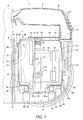
Fig. 1 is an explanatory sectional view showing an electric vacuum cleaner according to an embodiment of the present invention. -
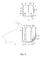
Fig. 2 is an explanatory sectional view showing a state before fitting the upper case to the lower case in a method for manufacturing the same electric vacuum cleaner. -
Fig. 3 is an explanatory sectional view showing a state where an electric blowing part is placed on an energizing member in the method for manufacturing the same electric vacuum cleaner. -
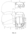
Fig. 4 is an explanatory sectional view showing a state where the upper case is covered in the method for manufacturing the same electric vacuum cleaner. -
Fig. 5 is a horizontal sectional view showing an essential portion of the same electric vacuum cleaner. -
Fig. 6 is an explanatory sectional view showing a support member of the same electric vacuum cleaner. -
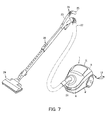
Fig. 7 is a perspective view showing the same electric vacuum cleaner. -
- 2
- Lower case
- 3
- Upper case
- 5
- Main body case
- 6
- Blowing chamber as housing chamber
- 11
- Electric blowing part
- 41
- Electric blower
- 42
- Motor cover as cover body
- 43
- Coil spring as blower support member
- 44
- Support bar as energizing member
- 45
- Support wheel as support member
- 85,98
- Supported portion
- 96
- Upper portion connector as upper portion connecting part
- 105
- Control board as control part
- 106
- Lowerportion connector as lower portion connecting part
- Hereinafter, a configuration of an electric vacuum cleaner according to an embodiment of the present invention will be described with reference to
Fig. 1 to Fig. 7 . - In
Fig. 1 to Fig. 7 , the reference numeral 1 denotes a vacuum cleaner main body, and the vacuum cleaner main body 1 is a so-called canister-type electric vacuum cleaner capable of running on a floor surface as a surface to be cleaned. - The vacuum cleaner main body 1 includes a
main body case 5 including: alower case 2 opened upward; anupper case 3 opposed to the upper rear side of thelower case 2 and covering the upper rear side of thelower case 2, and alid body 4 capable of opening and closing the upper front side of thelower case 2. In themain body case 5, a blowingchamber 6 as a housing chamber is partitioned between thelower case 2 and theupper case 3, adust collecting chamber 7 is partitioned between thelower case 2 and thelid body 4, and a partitioningwall part 8 partitioning the blowingchamber 6 anddust collecting chamber 7 is provided between these. - The blowing
chamber 6 is a space partitioned by connecting airtightly thelower case 2 and theupper case 3 via a seal packing not shown by using screws, etc., and houses a substantially cylindrical electric blowingpart 11 so that the axial direction of the electric blowing part is along the front-rear direction. The blowingchamber 6 communicates with the outside of themain body case 5 viaexhaust holes 12 opened in the rear portion of theupper case 3. Further, a cord reel chamber for housing a cord reel, around which apower cord 13 capable of supplying power from outside to the electric blowingpart 11 is wound, is partitioned at the side of the blowingchamber 6. - Here, in the cord reel chamber, the
power cord 13 can be led out from a cord leading outlet opened in the rear portion of thelower case 2. - On the other hand, into the
dust collecting chamber 7, a dust collecting part such as a paper pack or a cyclone dust collecting device can be removably attached. At the front portion of thedust collecting chamber 7, a mainbody suction port 21 is opened in thelower case 2. In the mainbody suction port 21, ahose body 22 is removably provided, and to a tip end portion of thehose body 22, ahand operation part 23 is provided. On thehand operation part 23, agrip part 25 to be gripped by an operator is protruded, and on thegrip part 25, a plurality of settingbuttons 26 to be used by an operator for setting an operation mode of theelectric blowing part 11 are provided. To the tip end portion of thehand operation part 23, anextension tube 28 and afloor brush 29 as a suction port body are successively communicatively connected. - The
partitioning wall part 8 includes arear partitioning wall 31 positioned at the rear portion on the blowingchamber 6 side, a front partitioning wall not shown positioned at the front portion on thedust collecting chamber 7 side, and side partitioning wall not shown which is continued to the front partitioning wall and partition the blowingchamber 6 and the cord reel chamber, and to the rear portion of the front partitioning wall, a driving part which actuates various mechanisms not shown inside the vacuum cleaner main body 1 is attached. - In the
rear partitioning wall 31, a circular rearportion communication hole 37 is opened, and in the front partitioning wall, a circular front portion communication hole is opened, and these rearportion communication hole 37 and front portion communication hole are connected airtightly by a duct not shown. - To the rear portion of the rear
portion communication hole 37, theelectric blowing part 11 is connected airtightly. On thedust collecting chamber 7 side on the front portion of the front portion communication hole, a filter not shown is disposed. - In the side partitioning walls, communication port which makes communication between the blowing
chamber 6 and the cord reel chamber communicate with each other are formed. - To the upper portions of the
rear partitioning wall 31, the front partitioning wall, and the side partitioning walls, a packing not shown as a sealing member which is sandwiched between these and theupper case 3 and for partitioning airtightly the blowingchamber 6, thedust collecting chamber 7, and the cord reel chamber, is attached. - The
electric blowing part 11 includes, as shown inFig. 1 to Fig. 5 , a fan motor, i.e.,electric blower 41 as a heavy object, a substantiallycylindrical motor cover 42 which is a comparatively lightweight cover body as a holding member which covers theelectric blower 41 like a capsule and holds it, and a plurality ofcoil springs 43 as blower support members which elastically support theelectric blower 41 on themotor cover 42 and attenuate rotational vibrations of theelectric blower 41, and is sandwiched from above and below by a plurality of, for example, front and rear pairs, i.e. , foursupport bars 44 which are support elastic parts as energizing members attached to thelower case 2 and a plurality of, for example, a pair ofsupport wheels 45 which are rotatable bodies as support members attached to theupper case 3. - The
electric blower 41 includes a bottomedcylindrical motor frame 47 as a case body, and a substantiallycylindrical fan cover 48 which is fitted to the front side on the opening side of themotor frame 47 and has a diameter larger than that of themotor frame 47, and is held inside themotor cover 42 so that the axial direction corresponds to that of themotor cover 42. To the periphery of themotor frame 47 of theelectric blower 41, an inner peripheralside spring support 51 and an outer peripheralside spring support 52 which are spring receiving rings as blower support member receivers are attached, and between these spring supports 51 and 52, coil springs 43 are held, and theelectric blower 41 is elastically supported to themotor cover 42 side. - Inside the
motor frame 47, anelectric motor 55 as a motor part that is a drive source is housed. Theelectric motor 55 is configured with arotary shaft 56 connected to a rotor blade, i.e., acentrifugal fan 57 covered by afan cover 48 so as to rotate thecentrifugal fan 57. - In the peripheral surface nearer the rear side of the
motor frame 47, a plurality ofquadrangular exhaust ports 61 are opened spaced at substantially even intervals in the circumferential direction, and into attachment holes not shown opened at positions between theseexhaust ports 61, brush mechanisms not shown which are electrically connected to the commutator of theelectric motor 55 are attached. - In the central portion of the
fan cover 48, anair suction port 66 is opened. - The
electric blower 41 suctions air from theair suction port 66 and exhausts the suctioned air from the inside of themotor frame 47 to the outside of themotor frame 47 via theexhaust ports 61 by thecentrifugal fan 57 rotated by theelectric motor 55, and accordingly, a negative pressure can be applied to the duct, thedust collecting chamber 7, the hose body 22 (Fig. 7 ), the extension tube 28 (Fig. 7 ), and the floor brush 29 (Fig. 7 ), etc. - The inner peripheral
side spring support 51 is made from, for example, synthetic resin or metal, etc., into a shape along the outer periphery of themotor frame 47, that is, for example, a ring shape, and is closely fitted to the periphery of themotor frame 47 to hold theelectric blower 41. The inner peripheralside spring support 51 is attached to themotor frame 47 so that the axial direction corresponds to that of theelectric blower 41, and the central region in the front-rear direction (axial direction) is located at a position corresponding to the center of gravity G of theelectric blower 41 nearer the front end of themotor frame 47 at the rear of thefan cover 48. The center of gravity of theelectric blower 41 substantially corresponds to the center of gravity of theelectric blowing part 11 in consideration of the weight difference between theelectric blower 41 and themotor cover 42, and therefore, hereinafter, the center of gravity G means the center of gravity of theelectric blower 41 and theelectric blowing part 11. Further, on the outer peripheral side of the inner peripheralside spring support 51, a plurality ofspring holding parts 71 as elastic body holding parts holding one end portions ofcoil springs 43 are formed at, for example, 3 positions. - Each of these
spring holding parts 71 includes a holdingcylindrical portion 71a to which one end of acoil spring 43 is fitted on the inner peripheral side and a protruding holdingportion 71b which protrudes radially inside the holdingcylindrical portion 71a and is inserted in thecoil spring 43 to hold thecoil spring 43, and thespring holding parts 71 are spaced by substantially equal angles, that is, 120 degrees in the present embodiment from each other in the circumferential direction of the inner peripheralside spring support 51. - On the other hand, the outer peripheral
side spring support 52 is made from, for example, synthetic resin or metal, etc., into a shape along the inner periphery of themotor cover 42, that is, for example, a ring shape with a diameter larger than that of the inner peripheralside spring support 51, and is disposed concentrically with the inner peripheralside spring support 51 and positioned on themotor cover 42 side. Therefore, the central region in the front-rear direction (axial direction) of the outer peripheralside spring support 52 is also at a position corresponding to the center of gravity G. On the inner peripheral side of the outer peripheralside spring support 52, corresponding to spring holdingparts 71 of the inner peripheralside spring support 51,spring holding parts 73 as elastic body holding parts for holding the other end portions of the coil springs 43 are formed. - Each of the
spring holding parts 73 includes a holdingcylindrical portion 73a to which one end of eachcoil spring 43 is fitted on the inner peripheral side, and a protrudingholdingportion 73b whichprotrudes radially inside the holdingcylindrical portion 73a and is inserted in thecoil spring 43 to hold thecoil spring 43. - Therefore, the coil springs 43 are attached radially to the
electric blower 41 between the spring supports 51 and 52, and spaced from each other by substantially equal angles. That is, one end portions on theelectric blower 41 side of the coil springs 43 are held toward the center of gravity G by thespring holding parts 71 of the inner peripheralside spring support 51, and the other end portions are held by thespring holding parts 73 of the outer peripheralside spring support 52. These coil springs 43 are disposed in an inverted Y shape on theelectric blower 41 when theelectric blowing part 11 is viewed in the axial direction. The spring supports 51 and 52 are joined integrally by the coil springs 43 and constitute asupport unit 74. - On the other hand, the
motor cover 42 includes afront motor cover 75 as a substantially cylindrical first motor cover, and arear motor cover 76 as a substantially cylindrical second motor cover to be connected to the rear portion of thefront motor cover 75. That is, themotor cover 42 is formed so as to be assembled and disassembled in the axial direction (thrust direction) of theelectric blowing part 11. The motor cover 42 houses theelectric blower 41 inside concentrically. - The
front motor cover 75 is made from, for example, synthetic resin, etc., and includes a substantially disk-shapedfront plate 81 which serves as a front lid and a frontperipheral wall 82 extending rearward from the outer peripheral edge portion of thefront plate 81, and at the substantially central portion of thefront plate 81, a circular frontportion communication opening 83 which is a communication opening for making communication between the rearportion communication hole 37 of themain body case 5 and theair suction port 66 of theelectric blower 41 is opened. Therefore, thefront motor cover 75 is opened at the rear end. - On the lower portion of the front
peripheral wall 82, for example, a pair of supported portions 85 (only one is shown) to be supported bysupport bars 44 on the front side are formed. The supportedportions 85 are portions to which the pair of support bars 44 on the front side are fitted from below, and are formed into arced shapes, in the present embodiment, spherical recessed shapes in a sectional view along a substantially vertical plane along the axial direction of theelectric blowing part 11, and open downward, and also open forward due to frontcontinuous portions 86 continuing forward horizontally to thefront plate 81. - To the front
portion communication opening 83, a substantiallycylindrical seal ring 88 which is a packing as a sealing member for airtightly connecting the rearportion communication hole 37 communicating with thedust collecting chamber 7 of themain body case 5 and theair suction port 66 of theelectric blower 41 on the negative pressure side of theelectric blowing part 11 is attached at the front portion between the frontportion communication opening 83 and therear partitioning wall 31. Theseal ring 88 is made from an elastic material such as, for example, rubber or elastomer into a substantially cylindrical shape, and serves as a vibration attenuating portion which attenuates vibrations in the axial direction of theelectric blowing part 11 by elastic deformation in the axial direction according to the vibrations so as not to transmit the vibrations to themain body case 5 via thepartitioning wall part 8. - The
seal ring 88 is attached so as to be slightly energized forward, that is, attached so that the front portion is slightly pressure-welded to the rear surface of therear partitioning wall 31 of thepartitioning wall part 8 in a state where theelectric blowing part 11 is stopped. Theseal ring 88 may be attached to therear partitioning wall 31 side. - On the other hand, the
rear motor cover 76 is made from, for example, synthetic resin, etc., and includes a substantially disk-shapedrear plate 91 which serves as a rear lid, a rearperipheral wall 92 extending forward from the outer peripheral edge portion of therear plate 91, and aflange portion 93 extending radially from the outer peripheral edge portion of the rearperipheral wall 92, and theflange portion 93 is connected to the rear end of the frontperipheral wall 82 of thefront motor cover 75 by, for example, screwing. - To the rear portion of the
rear plate 91, amotor cushion 95 as a cushioning member that is a buffer member is attached. Themotor cushion 95 is opposed to the rear portion of thelower case 2 via a predetermined gap, and by flexible deformation by contact with thelower case 2 when theelectric blowing part 11 moves rearward due to vibrations, the motor cushion absorbs an impact of the contact so as to make it difficult to transmit the impact to thelower case 2 side or theelectric blowing part 11 side. - To the lower portion of the rear
peripheral wall 92, anupper portion connector 96 as an upper portion connecting part electrically connected to theelectric blower 41 side, for example, a brush part of theelectric blower 41 is attached. In the lower portion of the rearperipheral wall 92, on the front side of theupper portion connector 96, rearportion communication openings 97 as communication openings serving as discharge ports which make communication between theexhaust ports 61 of theelectric blower 41 and the exhaust holes 12 of themain body case 5 are opened downward. Further, on both sides of the lower portion of the rearperipheral wall 92, supported portions 98 (only one is shown) to be supported by the support bars 44 on the rear side are formed, respectively. - The supported
portions 98 are portions to which the pair of support bars 44 on the rear side are fitted from below, and are formed into arced shapes, in the present embodiment, spherical recessed shapes in a sectional view along a substantially vertical plane along the axial direction of theelectric blowing part 11, and open downward and also open rearward due to rearcontinuous portions 99 continued forward horizontally to therear plate 91. - In the
flange portion 93, a plurality of screw holes for screwing are formed although these are not shown, and by screwing screws not shown into these screw holes, thefront motor cover 75 and therear motor cover 76 are fixed to each other. - Each
support bar 44 energizes theelectric blowing part 11 upward to attenuate vibrations in the up-down direction and the front-rear direction of theelectric blowing part 11, and as shown inFig. 6 , inside a plurality ofextensible portions 101 connected in an extensible manner, coil springs 102 which are energizing bodies are housed and formed into bar shapes long vertically, and the front pair of support bars and the rear pair of support bars are spaced from each other in the front-rear direction, and in each pair, the support bars are separated in the left-right direction. Specifically, the front pair of support bars and the rear pair of support bars are positioned at positions sandwiching the center of gravity G from the front and rear of theelectric blowing part 11, that is, the front pair is positioned ahead of the center of gravity G, and the rear pair is positioned at the rear of the center of gravity G, and in each pair, the support bars 44 are at positions sandwiching the center of gravity G from the left and right of theelectric blowing part 11, that is, theleft support bar 44 is on the left of the center of gravity G, and theright support bar 44 is on the right of the center of gravity G. For example, preferably, the front pair and the rear pair of the support bars 44 are made different from each other in pitch between the left and right support bars, and the pitch between the front and rear support bars and the pitch between the left and right support bars are made different from each other because this prevents assembly direction errors when fitting theelectric blowing part 11. - The
extensible portions 101 are formed into substantially cylindrical shapes so that their diameters become gradually larger from the upper end side to the lower end side, and theextensible portion 101a positioned at the top end serves as a piston part which is a support having a closed upper end portion. The upper end portion of theextensible portion 101a fits to the supportedportions motor cover 42, and is formed into an arced shape, in the present embodiment, a spherical recessed shape in a sectional view along a substantially vertical plane along the axial direction of theelectric blowing part 11. - The coil springs 102 are formed to be long, and have lower end portions fixed to the
lower case 2 and upper end portions connected to lower ends of theextensible portions 101a, and energize the entireextensible portions 101 upward except for theextensible portions 101 on the lower end via theextensible portions 101a. - As shown in
Fig. 2 , the upper end sides of theextensible portions 101a of the support bars 44 come to substantially the same height as that of the upper end of thelower case 2 and face the upper side of thelower case 2 in the state where the support bars 44 extend maximally, in the present embodiment, the coil springs 102 are naturally long, and in the state in the middle of an assembly operation where theelectric blowing part 11 is supported as shown inFig. 3 andFig. 4 , and in the state after the assembly operation where thelower case 2 and theupper case 3 are combined to sandwich theelectric blowing part 11 as shown inFig. 1 , energizing forces remain. In other words, the coil springs 102 are contractible in the states shown inFig. 1 ,Fig. 3 , andFig. 4 . Specifically, the coil springs 102 do not completely contract even in the state after the assembly operation shown inFig. 1 , and contraction allowances remain. - Here, the state where the upper end sides of the
extensible portions 101a are at substantially the same height as that of the upper end of thelower case 2 includes the state where the upper end sides of theextensible portions 101a are at the same height as that of the upper end of thelower case 2 and the state where the upper end sides are slightly lower or higher than the upper end of thelower case 2. - At the rear of the support bars 44 on the rear side, a
control board 105 as a control part which controls operations of theelectric blower 41, etc. , of theelectric blowing part 11 is disposed. Thecontrol board 105 is electrically connected to thepower cord 13 of the cord reel, and is connectable to the power supply side via thepower cord 13, and is electrically connected to thelower portion connector 106 as a lower portion connecting part, and is configured so that thelower portion connector 106 is electrically and mechanically connected to theelectric blowing part 11 via theupper portion connector 96 on theelectric blowing part 11 side. Specifically, thecontrol board 105 and thelower portion connector 106 are disposed at positions opposed to the rearportion communication openings 97 of theelectric blowing part 11 and in the exhaust air path communicating with the exhaust holes 12 from the rearportion communication openings 97. - The
lower portion connector 106 is attached to thelower case 2, and disposed so that the tip end side as a connecting side is directed toward the upper side, that is, theupper case 3 side. - The
support wheels 45 attenuate vibrations in the up-down direction and the front-rear direction of theelectric blowing part 11, and are made from an elastic material such as rubber or elastomer into roller shapes, and are axially supported turnably betweenaxial support plates lower plate 3a as an axial support part formed substantially horizontally on the lower portion of theupper case 3 andpositionedbetween the outer peripheral surface of the frontperipheral wall 82 of thefront motor cover 75 of themotor cover 42 and theupper case 3 as shown inFig. 5 , and axially supported rotatably in the front-rear direction, that is, the axial direction of theelectric blowing part 11. Further, thesupport wheels 45 are disposed at positions above the center of gravity G of theelectric blowing part 11 in a side view and at a side of the topportionof the outer peripheral surface on the upper side of thefront motor cover 75. Therefore, thesupport wheels 45 are attached radially to themotor cover 42, and the axial direction thereof is along the substantially tangential direction of the outer peripheral surface of thefront motor cover 75. Specifically, thesupport wheels 45 are disposed so as to incline toward the center of gravity G or the central axis side of theelectric blowing part 11. - Next, a method for manufacturing the electric vacuum cleaner of the embodiment described above will be described.
- First, in a state where the
support unit 74 including the spring supports 51 and 52 joined to each other by the coil springs 43 is attached to the outer periphery of themotor frame 47 of theelectric blower 41, theelectric blower 41 is covered from the front and rear sides by the motor covers 75 and 76 and fitted to themotor cover 42 to form theelectric blowing part 11. - Next, as shown in
Fig. 2 andFig. 3 , from above thelower case 2 to which the respective components are fitted, when theelectric blowing part 11 is placed so that the support bars 44 are fitted to the supportedportions extensible portions 101a of the support bars 44 are fitted to the supportedportions electric blowing part 11, theelectric blowing part 11 sinks to thelower case 2 side, and theupper portion connector 96 is opposed to the upper portion of thelower portion connector 106. - When the upper end portions of the
extensible portions 101a of the support bars 44 are not correctly fitted to the supportedportions electric blowing part 11 or bend to the center sides of the support bars 44, so that theelectric blowing part 11 is not correctly fixed or floats, and accordingly, an operator can easily confirm incorrect assembly of theelectric blowing part 11. - Further, in the state where the support bars 44 are correctly fittedto the
supportedportions upper case 3 to which the respective components are fitted and which is joined to thelid body 4 onto the upper portion of thelower case 2 from above as shown inFig. 4 , thesupport wheels 45 are brought into contact with the upper portion of theelectric blowing part 11, and from this state, as shown inFig. 1 , by fitting theupper case 3 and thelower case 2 by using screws, thesupport wheels 45 push theelectric blowing part 11 downward against the energization of the coil springs 102, and theupper case 3 is pressure-welded to the upper end portion of thepartitioning wallpart 8 via the packing, and accordingly, thedust collecting chamber 7 and the blowingchamber 6 are partitioned and theelectric blowing part 11 is housed in theblowing chamber 6 while being elastically sandwiched from the upper and lower sides, and the frontportion communication opening 83 of theelectric blowing part 11 communicates with the rearportion communication hole 37 via theseal ring 88. - Simultaneously, according to pushing of the
electric blowing part 11, theupper portion connector 96 is pushed into thelower portion connector 106, and theseconnectors - Next, operation of the embodiment described above will be described.
- When cleaning, first, the
hose body 22, theextension tube 28, and thefloor brush 2 9 are successively communicatively connected to the mainbody suction port 21, and thelid body 4 of themain body case 5 is opened and a paper pack is loaded in thedust collecting chamber 7, and thelid body 4 is closed. - In this state before starting cleaning, the
electric blowing part 11 is located at a predetermined start position in the axial direction (front-rear direction) by the balance of the energizing forces of the support bars 44 andsupport wheels 45. - When an operator pulls out the
power cord 13 from themain body case 5, connects the cord to an outlet on a wall or the like, grips thegrip part 25 and operates apredetermined setting button 26, theelectric blower 41 of theelectric blowing part 11 is driven. - Due to driving of the
electric blower 41 and a negative pressure generated by this driving, theelectric blowing part 11 is made to vibrate in the front-rear direction of the axial direction. - At this time, the
extensible portions 101a of the support bars 44 fit to the supportedportions electric blowing part 11, and accordingly, forces are applied in directions to push theextensible portions 101a into the contractedextensible portions 101 against the energization by the coil springs 102, however, theelectric blowing part 11 is energized forward, rearward, upward, or downward so as to be well-balanced by energization by the coil springs 102 or energization and rotation of thesupport wheels 45, that is, theelectric blowing part 11 is centered by the support bars 44 andsupport wheels 45, and the vibrations in the axial direction (front-rear direction) and the up-down direction accompanying driving of theelectric blowing part 11 are absorbed. - Further, due to driving of the
electric blower 41, inside theelectric blowing part 11, vibrations are made to generate in the radial direction (central axis direction) crossing the rotation direction of theelectric blower 41. - At this time, coil springs 43 energized toward the center of gravity G of the
electric blower 41 each properly expand and contract to center theelectric blower 41, and accordingly, vibration in the radial direction (central axis direction) accompanying drivingof theelectric blower 41 is also absorbed. - Then, according to a negative pressure caused by driving of the
electric blower 41, an air path which acts on thefloor brush 29, theextension tube 28, thehose body 22, the mainbody suction port 21, and the paper pack is formed, and dust is suctioned together with air. - The suctioned air becomes suctioning wind, and dust contained in the suctioning wind is caught by the paper pack when the air passes through the paper pack. The dust accommodated in the paper pack is compressed by the suctioning wind passing through it.
- Further, the suctioning wind which has passed through the paper pack passes through the filter, the front portion communication hole, the duct, and the rear
portion communication hole 37, and flows into the inside of thefan cover 48 of theelectric blower 41 via theair suction port 66 of theelectric blower 41, and suctioned from the central portion of thecentrifugal fan 57 and exhausted in the circumferential direction, and passes through the inside of themotor frame 47, and is exhausted to the outside of theelectric blower 41 as exhaust wind from theexhaust ports 61. - These exhaust winds are exhausted downward via the rear
portion communication openings 97 of themotor cover 42 and cool thecontrol board 105 and theconnectors electric blowing part 11 and is exhausted to the outside of themain body case 5 from the exhaust holes 12 of themain body case 5, and the residual flows into the cord reel chamber from the communication port of thepartitioning wall part 8 and is exhausted to the outside of themain body case 5 via the cord leading outlet while cooling the cord reel (power cord 13). - When cleaning is finished, the operator operates the
setting button 26 to stop theelectric blower 41 and stop the driving of the electric vacuum cleaner. - At this time, the
electric blowing part 11 returns to a predetermined start position by the centering operation of the support bars 44 and thesupport wheels 45. - When dust not less than a predetermined amount is accumulated in the paper pack, the operator opens the
lid body 4 and takes the paper pack out of thedust collecting chamber 7 and disposes of it together with dust, and loads a new paper pack in thedust collecting chamber 7. - As describedabove, according to the embodiment described above, the
electric blowing part 11 is placed on the support bars 44 formed so as to project upward from thelower case 2, and theelectric blowing part 11 is sandwiched between thesupport wheels upper case 3 onto thelower case 2, and accordingly, when theelectric blowing part 11 is fitted into the blowingchamber 6 of themain body case 5, without the operations of aligning theelectric blowingpart 11 and fitting various sealingmembers and buffer members to thelower case 2, theelectric blowing part 11 can be easily fitted into the blowingchamber 6, and accordingly, the manufacturability is improved. - Only by covering and attaching the
upper case 3 onto thelower case 2, theupper portion connector 96 electrically connected to thecontrol board 105 is connected to thelower portion connector 106 on thelower case 2 side electrically connectable to the power supply side, so that a wiring operation for connecting the power supply side and theelectric blowing part 11 side is not required separately, and the manufacturability is further improved. - In particular, it becomes unnecessary to secure, in the
blowing chamber 6, a space for wiring for connecting the power supply side and theelectric blowing part 11 side, so that themain body case 5 can be further downsized. - Moreover, as support members, by providing
support wheels electric blowing part 11, vibration in the axial direction of theelectric blowing part 11 can be more reliably absorbed by the rotations of thesupport wheels - By disposing three or more support bars 44 having bar shapes in the
blowing chamber 6, theelectric blowing part 11 can be stably supported by the support bars 44 when theelectric blowing part 11 is placed on the support bars 44. - Moreover, the tip end portions of the support bars 44 face the upper end of the
lower case 2 and project to substantially the same height as that of the upper end in the state before theelectric blowing part 11 is fitted, so that theelectric blowing part 11 can be easily placed on the support bars 44 without contact with structures, etc. , inside thelower case 2, and the fitting operability of theelectric blowing part 11 is further improved. - The support bars 44 are extensible while sandwiching the
electric blowing part 11 with thesupport wheels electric blowing part 11 is fitted into the blowingchamber 6, the support bars 44 can be made to function as vibration absorbing parts to absorb various vibrations accompanying driving of theelectric blowing part 11. - Specifically, by elastically supporting the
electric blowing part 11 from the front and rear sides of the center of gravity G by the support bars 44, vibrations accompanying driving of theelectric blowing part 11, especially vibration in the axial direction caused when starting theelectric blower 41 and vibration in the suction direction caused by a negative pressure generated by driving of theelectric blowing part 11 can be reliably absorbed by energization of the coil springs 102 of the support bars 44, and the vibrations can be isolated from themain body case 5. - Further, by forming the tip end sides of the
extensible portions 101a at the upper ends of the support bars 44 to have arced sectional shapes, and forming the supportedportions motor cover 42 of theelectric blowing part 11, to which the tip end portions of theextensible portions 101a are fitted, to have arced sectional shapes, not only vibration along the axial direction of theelectric blowing part 11 but also, for example, vibration diagonally downward of theelectric blowing part 11 can be reliably received by the support bars 44 as long as the vibration contains a component in the axial direction of theelectric blowing part 11, and the vibrations in the axial direction can be reliably absorbed. - By also disposing the support bars 44 in the width direction crossing the axial direction of the
electric blowing part 11, vibration in the width direction accompanying driving of theelectric blowing part 11 can also be absorbed by the support bars 44. - In the
electric blowing part 11, inside themotor cover 42, theelectric blower 41 is radially held toward the center of gravity G by the plurality of coil springs 43, so that the rotational vibrations when driving theelectric blower 41 can be absorbed by extension and contraction of the coil springs 43 and are hardly transmitted to themotor cover 42. - Moreover, these
coil springs 43 are at positions corresponding to the center of gravity G of theelectric blower 41 in a side view, so that, for example, in comparison with the case where the position nearer the front end or rear end of theelectric blower 41 is supported, vibration which is generated in the up-down direction on the front side or rear side of the center of gravity G when driving theelectric blower 41 can be minimized, and is hardly transmitted to themain body case 5. - Further, by adopting the configuration which prevents vibrations from being transmitted to the
main body case 5 as described above, noise caused by vibrations of theelectric blowing part 11 during driving of the electric vacuum cleaner can be prevented, and even when cleaning a wood floor which easily echoes the vibrations, the operationnoise becomes quiet, so that anelectric blower 41 whose vibrations are comparatively great can also be adopted, and the quality is stabilized. - In the embodiment described above, the
electric blowing part 11 is not limited to the electric blowing part configured to include theelectric blower 41 and themotor cover 42, and may be, for example, theelectric blower 41 itself. In other words, theelectric blower 41 which is elastically supported by the support bars 44 is also included in the embodiment. - The support bars 44 can provide the same operation and effect as long as at least three support bars, for example, one on the front side and two on the rear side, are disposed at positions at which the support bars can support the
electric blowing part 11. - Further, on the
upper case 3, instead of thesupport wheels 45, at least one arbitrary member such as an elastic body may be disposed as a support member. - The
upper case 3 does not necessarily constitute the upper portion of themain body case 5 as long as the upper case is attached to thelower case 2 so as to be opposed to at least a part of the upper side of thelower case 2, and includes, for example, a middle case constituting themain body case 5. - Details of the electric vacuum cleaner are not limited to those in the above-described configuration, and for example, upright-type and handy-type electric vacuum cleaners can also be used.
- The present invention is preferably applied to domestic electric vacuum cleaners and methods for manufacturing the same, etc.
Claims (9)
- An electric vacuum cleaner comprising:a main body case including a lower case and an upper case which is attached to the lower case so as to be opposed to at least a part of the upper portion of the lower case and partitions a housing chamber between the lower case and the upper case;an electric blowing part which has an axial direction and is housed in a housing chamber;an extensible energizing member which projects from the lower case side to the upper case side and supports the lower portion of the electric blowing part while energizing the lower portion at least upward; anda support member which is provided on the upper case side and sandwiches the electric blowing part with the energizing member.
- The electric vacuum cleaner according to Claim 1, wherein
the electric blowing part includes
an electric blower,
a cover body which covers at least a part of the electric blower, and
a blower support member which is disposed inside the cover body and supports the electric blower on the cover body. - The electric vacuum cleaner according to Claim 1 or 2, wherein
the support member is a rotary body rotatable along the axial direction of the electric blowing part. - The electric vacuum cleaner according to any one of Claims 1 to 3, wherein
three or more energizing members formed into bar shapes are disposed. - The electric vacuum cleaner according to any one of Claims 1 to 4, wherein
the energizing member is extensible while sandwiching the electric blowing part with the support member. - The electric vacuum cleaner according to any one of Claims 1 to 5, wherein
the energizing member has a tip end side having an arced shape in a sectional view, and
the electric blowing part includes a supported portion having an arced shape in a sectional view to which the tip end side of the energizing member is fitted. - The electric vacuum cleaner according to any one of Claims 1 to 6, comprising:a control part which controls the electric blowing part;an upper portion connecting part which is electrically connected to the control part and attached downward to the electric blowing part; anda lower portion connecting part which is attached upward to the lower case side, electrically connectable to a power supply side, and connected to the upper portion connecting part at least in a state where the upper case is attached to the lower case.
- A method for manufacturing an electric vacuum cleaner including a main body case including a lower case and an upper case which is attached to the lower case so as to be opposed to at least a part of the upper portion of the lower case and partitions a housing chamber between the lower case and the uppercase, an electric blowing part which has an axial direction and is housed in a housing chamber, an energizing member which projects from the lower case side to the upper case side and is extensible, and a support member which is provided on the upper case side, wherein
the electric blowing part is placed on the energizing member, and
the electric blowing part is sandwiched between the support member and the energizing member by covering and attaching the upper case onto the lower case. - The method for manufacturing an electric vacuum cleaner according to Claim 8, wherein
when the upper case is covered and attached onto the lower case, an upper portion connecting part electrically connected to a control part which controls the electric blowing part and attached downward to the electric blowing part is connected to a lower portion connecting part which is attached upward to the lower case side and electrically connectable to a power supply side.
Applications Claiming Priority (2)
| Application Number | Priority Date | Filing Date | Title |
|---|---|---|---|
| JP2008029120A JP4358278B2 (en) | 2008-02-08 | 2008-02-08 | Vacuum cleaner and method of manufacturing the same |
| PCT/JP2009/052086 WO2009099200A1 (en) | 2008-02-08 | 2009-02-06 | Electric cleaner and method of producing the same |
Publications (2)
| Publication Number | Publication Date |
|---|---|
| EP2253259A1 true EP2253259A1 (en) | 2010-11-24 |
| EP2253259A4 EP2253259A4 (en) | 2012-08-15 |
Family
ID=40952268
Family Applications (1)
| Application Number | Title | Priority Date | Filing Date |
|---|---|---|---|
| EP20090708935 Withdrawn EP2253259A4 (en) | 2008-02-08 | 2009-02-06 | Electric cleaner and method of producing the same |
Country Status (6)
| Country | Link |
|---|---|
| EP (1) | EP2253259A4 (en) |
| JP (1) | JP4358278B2 (en) |
| KR (1) | KR101252346B1 (en) |
| CN (1) | CN101932274B (en) |
| RU (1) | RU2429777C1 (en) |
| WO (1) | WO2009099200A1 (en) |
Cited By (2)
| Publication number | Priority date | Publication date | Assignee | Title |
|---|---|---|---|---|
| EP2510861A3 (en) * | 2011-04-12 | 2014-08-13 | BSH Bosch und Siemens Hausgeräte GmbH | Motor assembly for a domestic appliance powered by an electric motor |
| DE102016216292A1 (en) | 2016-08-30 | 2018-03-01 | BSH Hausgeräte GmbH | Vibration-decoupled and sound-reduced suspension of an engine in a vacuum cleaner |
Families Citing this family (1)
| Publication number | Priority date | Publication date | Assignee | Title |
|---|---|---|---|---|
| JP5707059B2 (en) * | 2010-05-28 | 2015-04-22 | 株式会社東芝 | Electric vacuum cleaner |
Family Cites Families (8)
| Publication number | Priority date | Publication date | Assignee | Title |
|---|---|---|---|---|
| DE519249C (en) * | 1929-03-06 | 1931-02-25 | Inventia Patent Verwert Ges | vacuum cleaner |
| US2076699A (en) * | 1935-12-19 | 1937-04-13 | Electrolux Corp | Vacuum cleaner |
| JPS56151070U (en) | 1980-04-10 | 1981-11-12 | ||
| JPH05337066A (en) * | 1992-06-12 | 1993-12-21 | Sanyo Electric Co Ltd | Vacuum cleaner |
| JP2580553Y2 (en) | 1992-11-13 | 1998-09-10 | 株式会社テック | Electric motor holding device |
| JP3864660B2 (en) * | 2000-01-28 | 2007-01-10 | 松下電器産業株式会社 | Electric vacuum cleaner |
| JP3814466B2 (en) * | 2000-06-28 | 2006-08-30 | 三菱電機株式会社 | Mobile phone |
| KR101212291B1 (en) * | 2005-12-30 | 2012-12-12 | 삼성전자주식회사 | Vaccum Air Cleaner |
-
2008
- 2008-02-08 JP JP2008029120A patent/JP4358278B2/en active Active
-
2009
- 2009-02-06 WO PCT/JP2009/052086 patent/WO2009099200A1/en not_active Ceased
- 2009-02-06 KR KR1020107018348A patent/KR101252346B1/en not_active Expired - Fee Related
- 2009-02-06 CN CN2009801040376A patent/CN101932274B/en active Active
- 2009-02-06 RU RU2010135528/12A patent/RU2429777C1/en not_active IP Right Cessation
- 2009-02-06 EP EP20090708935 patent/EP2253259A4/en not_active Withdrawn
Cited By (3)
| Publication number | Priority date | Publication date | Assignee | Title |
|---|---|---|---|---|
| EP2510861A3 (en) * | 2011-04-12 | 2014-08-13 | BSH Bosch und Siemens Hausgeräte GmbH | Motor assembly for a domestic appliance powered by an electric motor |
| DE102016216292A1 (en) | 2016-08-30 | 2018-03-01 | BSH Hausgeräte GmbH | Vibration-decoupled and sound-reduced suspension of an engine in a vacuum cleaner |
| DE102016216292B4 (en) | 2016-08-30 | 2024-05-16 | BSH Hausgeräte GmbH | Vibration-decoupled and noise-reduced suspension of a motor in a vacuum cleaner |
Also Published As
| Publication number | Publication date |
|---|---|
| JP4358278B2 (en) | 2009-11-04 |
| KR101252346B1 (en) | 2013-04-08 |
| JP2009183609A (en) | 2009-08-20 |
| CN101932274B (en) | 2012-08-29 |
| WO2009099200A1 (en) | 2009-08-13 |
| RU2429777C1 (en) | 2011-09-27 |
| CN101932274A (en) | 2010-12-29 |
| EP2253259A4 (en) | 2012-08-15 |
| KR20100103706A (en) | 2010-09-27 |
Similar Documents
| Publication | Publication Date | Title |
|---|---|---|
| EP2213216B1 (en) | Electric cleaner | |
| EP2252189B1 (en) | Electric vacuum cleaner | |
| KR101322489B1 (en) | Electric cleaner | |
| KR101641262B1 (en) | Robot cleaner | |
| EP1604603B1 (en) | Suction head of vacuum cleaner | |
| KR20160066399A (en) | Mop module and robot cleaner having the same | |
| KR101252346B1 (en) | Electric cleaner and method of producing the same | |
| JP2009207555A (en) | Electric vacuum cleaner | |
| JP2009183610A (en) | Electric vacuum cleaner | |
| KR20230120337A (en) | Cleaner | |
| JP5197044B2 (en) | Electric vacuum cleaner | |
| JP5707059B2 (en) | Electric vacuum cleaner | |
| JP2009207553A (en) | Electric vacuum cleaner | |
| JP2010259488A (en) | Electric vacuum cleaner | |
| JP4945665B2 (en) | Electric vacuum cleaner | |
| KR102367199B1 (en) | Robot cleaner | |
| KR102297759B1 (en) | Robot cleaner | |
| JP2009207554A (en) | Vacuum cleaner | |
| JP2013085701A (en) | Vacuum cleaner | |
| CN103892772A (en) | Vacuum cleaner | |
| JP2010172509A (en) | Vacuum cleaner |
Legal Events
| Date | Code | Title | Description |
|---|---|---|---|
| PUAI | Public reference made under article 153(3) epc to a published international application that has entered the european phase |
Free format text: ORIGINAL CODE: 0009012 |
|
| 17P | Request for examination filed |
Effective date: 20100902 |
|
| AK | Designated contracting states |
Kind code of ref document: A1 Designated state(s): AT BE BG CH CY CZ DE DK EE ES FI FR GB GR HR HU IE IS IT LI LT LU LV MC MK MT NL NO PL PT RO SE SI SK TR |
|
| AX | Request for extension of the european patent |
Extension state: AL BA RS |
|
| DAX | Request for extension of the european patent (deleted) | ||
| A4 | Supplementary search report drawn up and despatched |
Effective date: 20120716 |
|
| RIC1 | Information provided on ipc code assigned before grant |
Ipc: A47L 9/22 20060101AFI20120710BHEP Ipc: A47L 9/00 20060101ALI20120710BHEP |
|
| 17Q | First examination report despatched |
Effective date: 20140509 |
|
| STAA | Information on the status of an ep patent application or granted ep patent |
Free format text: STATUS: THE APPLICATION IS DEEMED TO BE WITHDRAWN |
|
| 18D | Application deemed to be withdrawn |
Effective date: 20150811 |