EP2252483B1 - A navigation assembly, a foldable mount and a navigation assembly including such a mount - Google Patents
A navigation assembly, a foldable mount and a navigation assembly including such a mount Download PDFInfo
- Publication number
- EP2252483B1 EP2252483B1 EP09704191A EP09704191A EP2252483B1 EP 2252483 B1 EP2252483 B1 EP 2252483B1 EP 09704191 A EP09704191 A EP 09704191A EP 09704191 A EP09704191 A EP 09704191A EP 2252483 B1 EP2252483 B1 EP 2252483B1
- Authority
- EP
- European Patent Office
- Prior art keywords
- mount
- arm
- speaker port
- navigation device
- navigation
- Prior art date
- Legal status (The legal status is an assumption and is not a legal conclusion. Google has not performed a legal analysis and makes no representation as to the accuracy of the status listed.)
- Active
Links
Images


Classifications
-
- B—PERFORMING OPERATIONS; TRANSPORTING
- B60—VEHICLES IN GENERAL
- B60R—VEHICLES, VEHICLE FITTINGS, OR VEHICLE PARTS, NOT OTHERWISE PROVIDED FOR
- B60R11/00—Arrangements for holding or mounting articles, not otherwise provided for
- B60R11/02—Arrangements for holding or mounting articles, not otherwise provided for for radio sets, television sets, telephones, or the like; Arrangement of controls thereof
- B60R11/0258—Arrangements for holding or mounting articles, not otherwise provided for for radio sets, television sets, telephones, or the like; Arrangement of controls thereof for navigation systems
-
- B—PERFORMING OPERATIONS; TRANSPORTING
- B60—VEHICLES IN GENERAL
- B60R—VEHICLES, VEHICLE FITTINGS, OR VEHICLE PARTS, NOT OTHERWISE PROVIDED FOR
- B60R11/00—Arrangements for holding or mounting articles, not otherwise provided for
- B60R2011/0042—Arrangements for holding or mounting articles, not otherwise provided for characterised by mounting means
- B60R2011/0049—Arrangements for holding or mounting articles, not otherwise provided for characterised by mounting means for non integrated articles
- B60R2011/0064—Connection with the article
- B60R2011/0071—Connection with the article using latches, clips, clamps, straps or the like
-
- B—PERFORMING OPERATIONS; TRANSPORTING
- B60—VEHICLES IN GENERAL
- B60R—VEHICLES, VEHICLE FITTINGS, OR VEHICLE PARTS, NOT OTHERWISE PROVIDED FOR
- B60R11/00—Arrangements for holding or mounting articles, not otherwise provided for
- B60R2011/0042—Arrangements for holding or mounting articles, not otherwise provided for characterised by mounting means
- B60R2011/0049—Arrangements for holding or mounting articles, not otherwise provided for characterised by mounting means for non integrated articles
- B60R2011/0064—Connection with the article
- B60R2011/0073—Connection with the article using key-type connections
-
- B—PERFORMING OPERATIONS; TRANSPORTING
- B60—VEHICLES IN GENERAL
- B60R—VEHICLES, VEHICLE FITTINGS, OR VEHICLE PARTS, NOT OTHERWISE PROVIDED FOR
- B60R11/00—Arrangements for holding or mounting articles, not otherwise provided for
- B60R2011/0042—Arrangements for holding or mounting articles, not otherwise provided for characterised by mounting means
- B60R2011/008—Adjustable or movable supports
- B60R2011/0082—Adjustable or movable supports collapsible, e.g. for storing after use
-
- B—PERFORMING OPERATIONS; TRANSPORTING
- B60—VEHICLES IN GENERAL
- B60R—VEHICLES, VEHICLE FITTINGS, OR VEHICLE PARTS, NOT OTHERWISE PROVIDED FOR
- B60R11/00—Arrangements for holding or mounting articles, not otherwise provided for
- B60R2011/0042—Arrangements for holding or mounting articles, not otherwise provided for characterised by mounting means
- B60R2011/008—Adjustable or movable supports
- B60R2011/0085—Adjustable or movable supports with adjustment by rotation in their operational position
Definitions
- the present invention relates to a navigation assembly. More particularly, but not exclusively, the present invention relates to a navigation assembly including a mount and a portable navigation device, a connector arm of the mount being connected to a portion of the periphery of a speaker port of the portable navigation device.
- a foldable mount More particularly, but not exclusively, the present invention relates to a foldable mount comprising a connector arm and a mount arm pivotally connected together and adapted to be folded between open and closed configurations.
- a navigation assembly including such a foldable mount.
- Portable navigation devices that include GPS (Global Positioning System) signal reception and processing functionality are well known and are widely employed as in-car or other vehicle navigation systems.
- GPS Global Positioning System
- a modem PND comprises a processor, memory (at least one of volatile and non-volatile, and commonly both), and map data stored within said memory.
- the processor and memory cooperate to provide an execution environment in which a software operating system may be established, and additionally it is commonplace for one or more additional software programs to be provided to enable the functionality of the PND to be controlled, and to provide various other functions.
- these devices further comprise one or more input interfaces that allow a user to interact with and control the device, and one or more output interfaces by means of which information may be relayed to the user.
- output interfaces include a visual display and a speaker for audible output.
- input interfaces include one or more physical buttons to control on/off operation or other features of the device (which buttons need not necessarily be on the device itself but could be on a steering wheel if the device is built into a vehicle), and a microphone for detecting user speech.
- the output interface display may be configured as a touch sensitive display (by means of a touch sensitive overlay or otherwise) to additionally provide an input interface by means of which a user can operate the device by touch.
- Devices of this type will also often include one or more physical connector interfaces by means of which power and optionally data signals can be transmitted to and received from the device, and optionally one or more wireless transmitters/receivers to allow communication over cellular telecommunications and other signal and data networks, for example Wi-Fi, Wi-Max GSM and the like.
- PND devices of this type also include a GPS antenna by means of which satellite-broadcast signals, including location data, can be received and subsequently processed to determine a current location of the device.
- the PND device may also include electronic gyroscopes and accelerometers which produce signals that can be processed to determine the current angular and linear acceleration, and in turn, and in conjunction with location information derived from the GPS signal, velocity and relative displacement of the device and thus the vehicle in which it is mounted.
- electronic gyroscopes and accelerometers which produce signals that can be processed to determine the current angular and linear acceleration, and in turn, and in conjunction with location information derived from the GPS signal, velocity and relative displacement of the device and thus the vehicle in which it is mounted.
- location information derived from the GPS signal, velocity and relative displacement of the device and thus the vehicle in which it is mounted.
- PNDs The utility of such PNDs is manifested primarily in their ability to determine a route between a first location (typically a start or current location) and a second location (typically a destination). These locations can be input by a user of the device, by any of a wide variety of different methods, for example by postcode, street name and house number, previously stored "well known" destinations (such as famous locations, municipal locations (such as sports grounds or swimming baths) or other points of interest), and favourite or recently visited destinations.
- the PND is enabled by software for computing a “best” or “optimum” route between the start and destination address locations from the map data.
- a “best” or “optimum” route is determined on the basis of predetermined criteria and need not necessarily be the fastest or shortest route.
- the selection of the route along which to guide the driver can be very sophisticated, and the selected route may take into account existing, predicted and dynamically and/or wirelessly received traffic and road information, historical information about road speeds, and the driver's own preferences for the factors determining road choice (for example the driver may specify that the route should not include motorways or toll roads).
- the device may continually monitor road and traffic conditions, and offer to or choose to change the route over which the remainder of the journey is to be made due to changed conditions.
- Real time traffic monitoring systems based on various technologies (e.g. mobile phone data exchanges, fixed cameras, GPS fleet tracking) are being used to identify traffic delays and to feed the information into notification systems.
- PNDs of this type may typically be mounted on the dashboard or windscreen of a vehicle, but may also be formed as part of an on-board computer of the vehicle radio or indeed as part of the control system of the vehicle itself.
- the navigation device may also be part of a hand-held system, such as a PDA (Portable Digital Assistant) a media player, a mobile phone or the like, and in these cases, the normal functionality of the hand-held system is extended by means of the installation of software on the device to perform both route calculation and navigation along a calculated route.
- PDA Portable Digital Assistant
- Route planning and navigation functionality may also be provided by a desktop or mobile computing resource running appropriate software.
- the Royal Automobile Club provides an on-line route planning and navigation facility at http://www.rac.co.uk, which facility allows a user to enter a start point and a destination whereupon the server to which the user's PC is connected calculates a route (aspects of which may be user specified), generates a map, and generates a set of exhaustive navigation instructions for guiding the user from the selected start point to the selected destination.
- the facility also provides for pseudo three-dimensional rendering of a calculated route, and route preview functionality which simulates a user travelling along the route and thereby provides the user with a preview of the calculated route.
- the user interacts with the navigation device to select the desired calculated route, optionally from a list of proposed routes.
- the user may intervene in, or guide the route selection process, for example by specifying that certain routes, roads, locations or criteria are to be avoided or are mandatory for a particular journey.
- the route calculation aspect of the PND forms one primary function, and navigation along such a route is another primary function.
- PNDs During navigation along a calculated route, it is usual for such PNDs to provide visual and/or audible instructions to guide the user along a chosen route to the end of that route, i.e. the desired destination. It is also usual for PNDs to display map information on-screen during the navigation, such information regularly being updated on-screen so that the map information displayed is representative of the current location of the device, and thus of the user or user's vehicle if the device is being used for in-vehicle navigation.
- An icon displayed on-screen typically denotes the current device location, and is centred with the map information of current and surrounding roads in the vicinity of the current device location and other map features also being displayed. Additionally, navigation information may be displayed, optionally in a status bar above, below or to one side of the displayed map information, examples of navigation information include a distance to the next deviation from the current road required to be taken by the user, the nature of that deviation possibly being represented by a further icon suggestive of the particular type of deviation, for example a left or right turn.
- the navigation function also determines the content, duration and timing of audible instructions by means of which the user can be guided along the route. As can be appreciated a simple instruction such as "turn left in 100 m" requires significant processing and analysis.
- user interaction with the device may be by a touch screen, or additionally or alternately by steering column mounted remote control, by voice activation or by any other suitable method.
- a further important function provided by the device is automatic route re-calculation in the event that: a user deviates from the previously calculated route during navigation (either by accident or intentionally); real-time traffic conditions dictate that an alternative route would be more expedient and the device is suitably enabled to recognize such conditions automatically, or if a user actively causes the device to perform route re-calculation for any reason.
- a route to be calculated with user defined criteria; for example, the user may prefer a scenic route to be calculated by the device, or may wish to avoid any roads on which traffic congestion is likely, expected or currently prevailing.
- the device software would then calculate various routes and weigh more favourably those that include along their route the highest number of points of interest (known as POIs) tagged as being for example of scenic beauty, or, using stored information indicative of prevailing traffic conditions on particular roads, order the calculated routes in terms of a level of likely congestion or delay on account thereof.
- POIs points of interest
- Other POI-based and traffic information-based route calculation and navigation criteria are also possible.
- route calculation and navigation functions are fundamental to the overall utility of PNDs, it is possible to use the device purely for information display, or "free-driving", in which only map information relevant to the current device location is displayed, and in which no route has been calculated and no navigation is currently being performed by the device. Such a mode of operation is often applicable when the user already knows the route along which it is desired to travel and does not require navigation assistance.
- Devices of the type described above for example the 720T model manufactured and supplied by TomTom International B. V., provide a reliable means for enabling users to navigate from one position to another.
- Tiny speakers tend to lack loudness and distort voice output which can make the voice output difficult to hear and/or understand.
- EP1652729 describes a modular article holder in which the holder has a support arm with a support arm head.
- An intermediate box is releasably mounted with one side, by a hook-like projection onto the arm head.
- the apparatus holder is releasably mounted by complementary slots onto another side of the intermediate box.
- the intermediate box includes a loudspeaker for transmitting sound generated by an apparatus engaged by the apparatus holder.
- the present invention seeks to overcome the problems of the prior art.
- the present invention provides a navigation assembly as set out in claim 1.
- the periphery of the speaker port both defines the speaker port and acts as points of connection for the mount. This enables larger speakers to be included in the PND for the same PND size. As the connector arm does not cover at least a portion of the speaker port this reduces distortion of the emitted voice instructions.
- the speaker port periphery is inclined to the surrounding housing.
- the connector arm defines an aperture, the aperture being arranged such that it overlies at least a portion of the speaker port when the connector arm is connected to the speaker port periphery.
- the speaker port can comprise an aperture in the housing, the portable navigation device further comprising a speaker within the speaker port.
- the speaker port comprises a plurality of apertures defining a mesh
- the portable navigation device further comprising a speaker within the housing behind the mesh.
- the mount further comprises a mount arm for connection to a surface, the mount arm being pivotally connected to the connector arm such that the mount can be folded from an open configuration with the connector arm inclined to the mount arm to a closed configuration with the mount arm adjacent to the connector arm.
- the mount arm can be adapted to be at least partially received in the aperture in the connector arm when the mount is in the closed configuration.
- the connector arm comprises an aperture, the mount arm being adapted to be at least partially received in the aperture when the mount is in the closed configuration.
- a portable navigation device is intended to include (without limitation) a portable personal computer (PC), mobile telephone or portable digital assistant (PDA)) executing route planning and navigation software.
- PC personal computer
- PDA portable digital assistant
- Fig. 1 illustrates an example view of Global Positioning System (GPS), usable by navigation devices.
- GPS Global Positioning System
- NAVSTAR the GPS incorporates a plurality of satellites which orbit the earth in extremely precise orbits. Based on these precise orbits, GPS satellites can relay their location to any number of receiving units.
- the GPS system is implemented when a device, specially equipped to receive GPS data, begins scanning radio frequencies for GPS satellite signals. Upon receiving a radio signal from a GPS satellite, the device determines the precise location of that satellite via one of a plurality of different conventional methods. The device will continue scanning, in most instances, for signals until it has acquired at least three different satellite signals (noting that position is not normally, but can be determined, with only two signals using other triangulation techniques). Implementing geometric triangulation, the receiver utilizes the three known positions to determine its own two-dimensional position relative to the satellites. This can be done in a known manner. Additionally, acquiring a fourth satellite signal will allow the receiving device to calculate its three dimensional position by the same geometrical calculation in a known manner. The position and velocity data can be updated in real time on a continuous basis by an unlimited number of users.
- the GPS system is denoted generally by reference numeral 100.
- a plurality of satellites 120 are in orbit about the earth 124.
- the orbit of each satellite 120 is not necessarily synchronous with the orbits of other satellites 120 and, in fact, is likely asynchronous.
- a GPS receiver 140 is shown receiving spread spectrum GPS satellite signals 160 from the various satellites 120.
- the spread spectrum signals 160 continuously transmitted from each satellite 120, utilize a highly accurate frequency standard accomplished with an extremely accurate atomic clock.
- Each satellite 120 as part of its data signal transmission 160, transmits a data stream indicative of that particular satellite 120.
- the GPS receiver device 140 generally acquires spread spectrum GPS satellite signals 160 from at least three satellites 120 for the GPS receiver device 140 to calculate its two-dimensional position by triangulation. Acquisition of an additional signal, resulting in signals 160 from a total of four satellites 120, permits the GPS receiver device 140 to calculate its three-dimensional position in a known manner.
- FIG. 2 is an illustrative representation of electronic components of a known portable navigation device 200 in block component format. It should be noted that the block diagram of the portable navigation device 200 is not inclusive of all components of the portable navigation device, but is only representative of many example components.
- the portable navigation device 200 comprises a processor 210 connected to an input device 220 and a display screen 240.
- the input device 220 can include a keyboard device, voice input device, touch panel and/or any other known input device utilised to input information; and the display screen 240 can include any type of display screen such as an LCD display, for example.
- the input device 220 and display screen 240 are integrated into an integrated input and display device, including a touchpad or touchscreen input so that a user need only touch a portion of the display screen 240 to select one of a plurality of display choices or to activate one of a plurality of virtual buttons.
- the portable navigation device may include an output device 260, for example an audible output device (e.g. a loudspeaker).
- output device 260 can produce audible information for a user of the portable navigation device 200, it is should equally be understood that input device 240 can include a microphone and software for receiving input voice commands as well.
- processor 210 is operatively connected to and set to receive input information from input device 220 via a connection 225, and operatively connected to at least one of display screen 240 and output device 260, via output connections 245, to output information thereto. Further, the processor 210 is operably coupled to a memory resource 230 via connection 235 and is further adapted to receive/send information from/to input/output (I/O) ports 270 via connection 275, wherein the I/O port 270 is connectible to an I/O device 280 external to the navigation device 200.
- I/O input/output
- the memory resource 230 comprises, for example, a volatile memory, such as a Random Access Memory (RAM) and a non-volatile memory, for example a digital memory, such as a flash memory.
- the external I/O device 280 may include, but is not limited to an external listening device such as an earpiece for example.
- connection to I/O device 280 can further be a wired or wireless connection to any other external device such as a car stereo unit for hands-free operation and/or for voice activated operation for example, for connection to an ear piece or head phones, and/or for connection to a mobile phone for example, wherein the mobile phone connection may be used to establish a data connection between the portable navigation device 200 and the internet or any other network for example, and/or to establish a connection to a server via the internet or some other network for example.
- any other external device such as a car stereo unit for hands-free operation and/or for voice activated operation for example, for connection to an ear piece or head phones, and/or for connection to a mobile phone for example
- the mobile phone connection may be used to establish a data connection between the portable navigation device 200 and the internet or any other network for example, and/or to establish a connection to a server via the internet or some other network for example.
- Fig. 2 further illustrates an operative connection between the processor 210 and an antenna/receiver 250 via connection 255, wherein the antenna/receiver 250 can be a GPS antenna/receiver for example.
- the antenna and receiver designated by reference numeral 250 are combined schematically for illustration, but that the antenna and receiver may be separately located components, and that the antenna may be a GPS patch antenna or helical antenna for example.
- the electronic components shown in Fig. 2 are powered by power sources (not shown) in a conventional manner.
- power sources not shown
- different configurations of the components shown in Fig. 2 are possible.
- the components shown in Fig. 2 may be in communication with one another via wired and/or wireless connections and the like.
- the portable navigation device 200 may establish a "mobile" or telecommunications network connection with a server 302 via a mobile device (not shown) (such as a mobile phone, PDA, and/or any device with mobile phone technology) establishing a digital connection (such as a digital connection via known Bluetooth technology for example). Thereafter, through its network service provider, the mobile device can establish a network connection (through the internet for example) with a server 302. As such, a "mobile" network connection is established between the portable navigation device 200 and the server 302 to provide a "real-time" or at least very “up to date” gateway for information.
- the establishing of the network connection between the mobile device (via a service provider) and another device such as the server 302, using an internet (such as the World Wide Web) for example, can be done in a known manner. This can include use of TCP/IP layered protocol for example.
- the mobile device can utilize any number of communication standards such as CDMA, GSM, WAN, etc.
- an internet connection may be utilised which is achieved via data connection, via a mobile phone or mobile phone technology within the navigation device 200 for example.
- an internet connection between the server 302 and the navigation device 200 is established. This can be done, for example, through a mobile phone or other mobile device and a GPRS (General Packet Radio Service)-connection (GPRS connection is a high-speed data connection for mobile devices provided by telecom operators; GPRS is a method to connect to the internet).
- GPRS General Packet Radio Service
- the portable navigation device 200 can further complete a data connection with the mobile device, and eventually with the internet and server 302, via existing Bluetooth technology for example, in a known manner, wherein the data protocol can utilize any number of standards, such as the GSRM, the Data Protocol Standard for the GSM standard, for example.
- the data protocol can utilize any number of standards, such as the GSRM, the Data Protocol Standard for the GSM standard, for example.
- the portable navigation device 200 may include its own mobile phone technology within the portable navigation device 200 itself (including an antenna for example, or optionally using the internal antenna of the portable navigation device 200).
- the mobile phone technology within the portable navigation device 200 can include internal components as specified above, and/or can include an insertable card (e.g. Subscriber Identity Module or SIM card), complete with necessary mobile phone technology and/or an antenna for example.
- mobile phone technology within the portable navigation device 200 can similarly establish a network connection between the portable navigation device 200 and the server 302, via the internet for example, in a manner similar to that of any mobile device.
- a Bluetooth enabled portable navigation device may be used to correctly work with the ever changing spectrum of mobile phone models, manufacturers, etc., model/manufacturer specific settings may be stored on the portable navigation device 200 for example. The data stored for this information can be updated.
- the navigation device 200 is depicted as being in communication with the server 302 via a generic communications channel 318 that can be implemented by any of a number of different arrangements.
- the server 302 and a portable navigation device 200 can communicate when a connection via communications channel 318 is established between the server 302 and the portable navigation device 200 (noting that such a connection can be a data connection via mobile device, a direct connection via personal computer via the internet, etc.).
- the server 302 includes, in addition to other components which may not be illustrated, a processor 304 operatively connected to a memory 306 and further operatively connected, via a wired or wireless connection 314, to a mass data storage device 312.
- the processor 304 is further operatively connected to transmitter 308 and receiver 310, to transmit and send information to and from portable navigation device 200 via communications channel 318.
- the signals sent and received may include data, communication, and/or other propagated signals.
- the transmitter 308 and receiver 310 may be selected or designed according to the communications requirement and communication technology used in the communication design for the portable navigation device 200. Further, it should be noted that the functions of transmitter 308 and receiver 310 may be combined into a signal transceiver.
- Server 302 is further connected to (or includes) a mass storage device 312, noting that the mass storage device 312 may be coupled to the server 302 via communication link 314.
- the mass storage device 312 contains a store of navigation data and map information, and can again be a separate device from the server 302 or can be incorporated into the server 302.
- the portable navigation device 200 is adapted to communicate with the server 302 through communications channel 318, and includes processor, memory, etc. as previously described with regard to Fig. 2 , as well as transmitter 320 and receiver 322 to send and receive signals and/or data through the communications channel 318, noting that these devices can further be used to communicate with devices other than server 302. Further, the transmitter 320 and receiver 322 are selected or designed according to communication requirements and communication technology used in the communication design for the portable navigation device 200 and the functions of the transmitter 320 and receiver 322 may be combined into a single transceiver.
- Software stored in server memory 306 provides instructions for the processor 304 and allows the server 302 to provide services to the portable navigation device 200.
- One service provided by the server 302 involves processing requests from the portable navigation device 200 and transmitting navigation data from the mass data storage 312 to the portable navigation device 200.
- Another service provided by the server 302 includes processing the navigation data using various algorithms for a desired application and sending the results of these calculations to the portable navigation device 200.
- the communication channel 318 generically represents the propagating medium or path that connects the portable navigation device 200 and the server 302.
- Both the server 302 and portable navigation device 200 include a transmitter for transmitting data through the communication channel and a receiver for receiving data that has been transmitted through the communication channel.
- the communication channel 318 includes telephone and computer networks. Furthermore, the communication channel 318 may be capable of accommodating wireless communication such as radio frequency, microwave frequency, infrared communication, etc. Additionally, the communication channel 318 can accommodate satellite communication.
- the communication signals transmitted through the communication channel 318 include, but are not limited to, signals as may be required or desired for given communication technology.
- the signals may be adapted to be used in cellular communication technology such as Time Division Multiple Access (TDMA), Frequency Division Multiple Access (FDMA), Code Division Multiple Access (CDMA), Global System for Mobile Communications (GSM), etc.
- TDMA Time Division Multiple Access
- FDMA Frequency Division Multiple Access
- CDMA Code Division Multiple Access
- GSM Global System for Mobile Communications
- Both digital and analogue signals can be transmitted through the communication channel 318.
- These signals may be modulated, encrypted and/or compressed signals as may be desirable for the communication technology.
- the server 302 includes a remote server accessible by the navigation device 200 via a wireless channel.
- the server 302 may include a network server located on a local area network (LAN), wide area network (WAN), virtual private network (VPN), etc.
- LAN local area network
- WAN wide area network
- VPN virtual private network
- the server 302 may include a personal computer such as a desktop or laptop computer, and the communication channel 318 may be a cable connected between the personal computer and the portable navigation device 200.
- a personal computer may be connected between the portable navigation device 200 and the server 302 to establish an internet connection between the server 302 and the portable navigation device 200.
- a mobile telephone or other handheld device may establish a wireless connection to the internet, for connecting the portable navigation device 200 to the server 302 via the internet.
- the portable navigation device 200 may be provided with information from the server 302 via information downloads which may be periodically updated automatically or upon a user connecting portable navigation device 200 to the server 302 and/or may be more dynamic upon a more constant or frequent connection being made between the server 302 and portable navigation device 200 via a wireless mobile connection device and TCP/IP connection for example.
- the processor 304 in the server 302 may be used to handle the bulk of the processing needs, however, processor 210 of portable navigation device 200 can also handle much processing and calculation, oftentimes independent of a connection to a server 302.
- a portable navigation device 200 includes a processor 210, an input device 220, and a display screen 240.
- the input device 220 and display screen 240 are integrated into an integrated input and display device to enable both input of information (via direct input, menu selection, etc.) and display of information through a touch panel screen, for example.
- a touch panel screen for example.
- Such a screen may be a touch input LCD screen, for example, as is well known to those of ordinary skill in the art.
- the portable navigation device 200 can also include any additional input device 220 and/or any additional output device 241, such as audio input/output devices for example.
- the navigation assembly 400 comprises a portable navigation device 401 which may for example be a PND as described with reference to either of figures 2 or 3 .
- the portable navigation device 401 comprises a housing 402.
- a portion of the rear face 403 of the housing comprises a speaker port periphery 404 which defines a speaker port 405 as shown.
- the speaker port periphery 404 is inclined to the adjacent portion of the housing 402 as shown.
- a speaker 406 Arranged within the speaker port 405 is a speaker 406.
- the navigation assembly 400 further comprises a foldable mount 407.
- the foldable mount 407 comprises a connector arm 408 and a mount arm 409.
- the two arms 408, 409 are pivotally connected together at a pivot point 410.
- the mount 407 may be folded between open and closed configurations by pivoting the connector arm 408 about the pivot point 410 with respect to the mount arm 407.
- FIG. 5 Shown in figure 5 is the mount 407 in the open configuration with the connector arm 408 inclined to the mount arm 409.
- the connector arm 408 is shown attached to the speaker port periphery 404.
- the connector arm 408 is snap fit into engagement with the speaker port periphery 404.
- the connector arm 408 may be released by sharply pulling the connector arm 408 and portable navigation device 401 apart.
- An aperture 411 extends through the connector arm 408.
- the aperture 411 is arranged such that when the connector arm 408 is connected to the speaker port periphery 404 the aperture 411 overlies the speaker port 405 as shown. Sound generated by the speaker 406 within the speaker port 405 is therefore not distorted by the connector arm 408.
- the mount arm 409 comprises a mount arm connector 412 for connecting the mount 407 to a surface such as a windscreen or dashboard.
- the mount arm connector 412 comprises an elastomeric disc and a camming mechanism which draws the centre of the disc upwards to create a vacuum between the disc and the surface to which it is affixed.
- FIG 6 Shown in figure 6 is the foldable mount 407 in the closed configuration with the mount arm 409 adjacent to the connector arm 408.
- the connector arm 408 and mount arm 409 are designed such that when in the closed configuration the mount arm 409 fits partially within the aperture 411 in the connector arm 408 as shown so reducing the thickness of the mount 407.
- the navigation assembly 400 When not in use the navigation assembly 400 is typically stored as shown in figure 6 with the portable navigation device 401 connected to the connector arm 408 of the mount 407, the mount 407 being folded in the closed configuration. In this configuration the navigation assembly 400 is sufficiently compact that it can easily be stored in a pocket or briefcase if required.
- the mount 407 When it is desired to use the navigation assembly 400 the mount 407 is unfolded to the open configuration. The elastomeric disc is pushed against a surface and the camming mechanism then rotated, deforming the disk and fixing the mount 407 in place.
- the camming mechanism When the user has finished using the navigation assembly 400 the camming mechanism is rotated in the opposite direction freeing the elastomeric disk from the surface to which it is attached. The mount 407 is then folded back to the closed configuration.
- the connector arm 408 snap fits into engagement with the speaker port periphery 404.
- other types of connection to the speaker port periphery 404 are possible.
- the connector arm 408 and PND 401 may be screwed together by means of corresponding threads on the connector arm 408 and speaker port periphery 404.
- the mount arm 409 comprises a simple elastomeric disk which is pushed into contact with a surface.
- the speaker port 405 is an aperture in the housing 402 of the portable navigation device 401.
- the speaker port 405 comprises a plurality of apertures defining a mesh.
- a speaker 406 is contained within the PND 401 behind the mesh.
- the connector arm 408 extends only a portion of the way around the periphery of the speaker port 405. If the speaker port 405 is circular then the connector arm 408 has a uniform curvature. If the speaker port 405 is other than circular, for example oval, square or oblong then the curvature of the connector arm 408 varies along its length to match a portion of the periphery of the speaker port 405. In each case the connector arm 408 is dimensioned such that when it is connected to the speaker port periphery 404 at least a portion of the speaker port 405 is not covered by the connector arm 408.
Abstract
Description
- The present invention relates to a navigation assembly. More particularly, but not exclusively, the present invention relates to a navigation assembly including a mount and a portable navigation device, a connector arm of the mount being connected to a portion of the periphery of a speaker port of the portable navigation device. In a further aspect of the invention there is provided a foldable mount. More particularly, but not exclusively, the present invention relates to a foldable mount comprising a connector arm and a mount arm pivotally connected together and adapted to be folded between open and closed configurations. In a further aspect of the invention there is provided a navigation assembly including such a foldable mount.
- Portable navigation devices (PNDs) that include GPS (Global Positioning System) signal reception and processing functionality are well known and are widely employed as in-car or other vehicle navigation systems.
- In general terms, a modem PND comprises a processor, memory (at least one of volatile and non-volatile, and commonly both), and map data stored within said memory. The processor and memory cooperate to provide an execution environment in which a software operating system may be established, and additionally it is commonplace for one or more additional software programs to be provided to enable the functionality of the PND to be controlled, and to provide various other functions.
- Typically these devices further comprise one or more input interfaces that allow a user to interact with and control the device, and one or more output interfaces by means of which information may be relayed to the user. Illustrative examples of output interfaces include a visual display and a speaker for audible output. Illustrative examples of input interfaces include one or more physical buttons to control on/off operation or other features of the device (which buttons need not necessarily be on the device itself but could be on a steering wheel if the device is built into a vehicle), and a microphone for detecting user speech. In a particularly preferred arrangement the output interface display may be configured as a touch sensitive display (by means of a touch sensitive overlay or otherwise) to additionally provide an input interface by means of which a user can operate the device by touch.
- Devices of this type will also often include one or more physical connector interfaces by means of which power and optionally data signals can be transmitted to and received from the device, and optionally one or more wireless transmitters/receivers to allow communication over cellular telecommunications and other signal and data networks, for example Wi-Fi, Wi-Max GSM and the like.
- PND devices of this type also include a GPS antenna by means of which satellite-broadcast signals, including location data, can be received and subsequently processed to determine a current location of the device.
- The PND device may also include electronic gyroscopes and accelerometers which produce signals that can be processed to determine the current angular and linear acceleration, and in turn, and in conjunction with location information derived from the GPS signal, velocity and relative displacement of the device and thus the vehicle in which it is mounted. Typically such features are most commonly provided in in-vehicle navigation systems, but may also be provided in PND devices if it is expedient to do so.
- The utility of such PNDs is manifested primarily in their ability to determine a route between a first location (typically a start or current location) and a second location (typically a destination). These locations can be input by a user of the device, by any of a wide variety of different methods, for example by postcode, street name and house number, previously stored "well known" destinations (such as famous locations, municipal locations (such as sports grounds or swimming baths) or other points of interest), and favourite or recently visited destinations.
- Typically, the PND is enabled by software for computing a "best" or "optimum" route between the start and destination address locations from the map data. A "best" or "optimum" route is determined on the basis of predetermined criteria and need not necessarily be the fastest or shortest route. The selection of the route along which to guide the driver can be very sophisticated, and the selected route may take into account existing, predicted and dynamically and/or wirelessly received traffic and road information, historical information about road speeds, and the driver's own preferences for the factors determining road choice (for example the driver may specify that the route should not include motorways or toll roads).
- In addition, the device may continually monitor road and traffic conditions, and offer to or choose to change the route over which the remainder of the journey is to be made due to changed conditions. Real time traffic monitoring systems, based on various technologies (e.g. mobile phone data exchanges, fixed cameras, GPS fleet tracking) are being used to identify traffic delays and to feed the information into notification systems.
- PNDs of this type may typically be mounted on the dashboard or windscreen of a vehicle, but may also be formed as part of an on-board computer of the vehicle radio or indeed as part of the control system of the vehicle itself. The navigation device may also be part of a hand-held system, such as a PDA (Portable Digital Assistant) a media player, a mobile phone or the like, and in these cases, the normal functionality of the hand-held system is extended by means of the installation of software on the device to perform both route calculation and navigation along a calculated route.
- Route planning and navigation functionality may also be provided by a desktop or mobile computing resource running appropriate software. For example, the Royal Automobile Club (RAC) provides an on-line route planning and navigation facility at http://www.rac.co.uk, which facility allows a user to enter a start point and a destination whereupon the server to which the user's PC is connected calculates a route (aspects of which may be user specified), generates a map, and generates a set of exhaustive navigation instructions for guiding the user from the selected start point to the selected destination. The facility also provides for pseudo three-dimensional rendering of a calculated route, and route preview functionality which simulates a user travelling along the route and thereby provides the user with a preview of the calculated route.
- In the context of a PND, once a route has been calculated, the user interacts with the navigation device to select the desired calculated route, optionally from a list of proposed routes. Optionally, the user may intervene in, or guide the route selection process, for example by specifying that certain routes, roads, locations or criteria are to be avoided or are mandatory for a particular journey. The route calculation aspect of the PND forms one primary function, and navigation along such a route is another primary function.
- During navigation along a calculated route, it is usual for such PNDs to provide visual and/or audible instructions to guide the user along a chosen route to the end of that route, i.e. the desired destination. It is also usual for PNDs to display map information on-screen during the navigation, such information regularly being updated on-screen so that the map information displayed is representative of the current location of the device, and thus of the user or user's vehicle if the device is being used for in-vehicle navigation.
- An icon displayed on-screen typically denotes the current device location, and is centred with the map information of current and surrounding roads in the vicinity of the current device location and other map features also being displayed. Additionally, navigation information may be displayed, optionally in a status bar above, below or to one side of the displayed map information, examples of navigation information include a distance to the next deviation from the current road required to be taken by the user, the nature of that deviation possibly being represented by a further icon suggestive of the particular type of deviation, for example a left or right turn. The navigation function also determines the content, duration and timing of audible instructions by means of which the user can be guided along the route. As can be appreciated a simple instruction such as "turn left in 100 m" requires significant processing and analysis. As previously mentioned, user interaction with the device may be by a touch screen, or additionally or alternately by steering column mounted remote control, by voice activation or by any other suitable method.
- A further important function provided by the device is automatic route re-calculation in the event that: a user deviates from the previously calculated route during navigation (either by accident or intentionally); real-time traffic conditions dictate that an alternative route would be more expedient and the device is suitably enabled to recognize such conditions automatically, or if a user actively causes the device to perform route re-calculation for any reason.
- It is also known to allow a route to be calculated with user defined criteria; for example, the user may prefer a scenic route to be calculated by the device, or may wish to avoid any roads on which traffic congestion is likely, expected or currently prevailing. The device software would then calculate various routes and weigh more favourably those that include along their route the highest number of points of interest (known as POIs) tagged as being for example of scenic beauty, or, using stored information indicative of prevailing traffic conditions on particular roads, order the calculated routes in terms of a level of likely congestion or delay on account thereof. Other POI-based and traffic information-based route calculation and navigation criteria are also possible.
- Although the route calculation and navigation functions are fundamental to the overall utility of PNDs, it is possible to use the device purely for information display, or "free-driving", in which only map information relevant to the current device location is displayed, and in which no route has been calculated and no navigation is currently being performed by the device. Such a mode of operation is often applicable when the user already knows the route along which it is desired to travel and does not require navigation assistance.
- Devices of the type described above, for example the 720T model manufactured and supplied by TomTom International B. V., provide a reliable means for enabling users to navigate from one position to another.
- When a user is driving between destinations they primarily rely on voice instructions from the PND. When receiving voice instructions the driver has to filter out road noise, engine noise, conversations within the vehicles, the radio etc. Existing PND devices tend to have tiny speakers on the rear face. The is because a significant portion of the rear face is typically used to secure the PND to an arm which is in turn secured to a car windscreen or dashboard. Tiny speakers tend to lack loudness and distort voice output which can make the voice output difficult to hear and/or understand.
-
EP1652729 describes a modular article holder in which the holder has a support arm with a support arm head. An intermediate box is releasably mounted with one side, by a hook-like projection onto the arm head. The apparatus holder is releasably mounted by complementary slots onto another side of the intermediate box. The intermediate box includes a loudspeaker for transmitting sound generated by an apparatus engaged by the apparatus holder. - The present invention seeks to overcome the problems of the prior art.
- In a first aspect the present invention provides a navigation assembly as set out in claim 1.
- In this arrangement, the periphery of the speaker port both defines the speaker port and acts as points of connection for the mount. This enables larger speakers to be included in the PND for the same PND size. As the connector arm does not cover at least a portion of the speaker port this reduces distortion of the emitted voice instructions.
- Preferably, the speaker port periphery is inclined to the surrounding housing.
- Preferably, the connector arm defines an aperture, the aperture being arranged such that it overlies at least a portion of the speaker port when the connector arm is connected to the speaker port periphery.
- The speaker port can comprise an aperture in the housing, the portable navigation device further comprising a speaker within the speaker port.
- Alternatively, the speaker port comprises a plurality of apertures defining a mesh, the portable navigation device further comprising a speaker within the housing behind the mesh.
- Preferably, the mount further comprises a mount arm for connection to a surface, the mount arm being pivotally connected to the connector arm such that the mount can be folded from an open configuration with the connector arm inclined to the mount arm to a closed configuration with the mount arm adjacent to the connector arm.
- The mount arm can be adapted to be at least partially received in the aperture in the connector arm when the mount is in the closed configuration.
- Preferably, the connector arm comprises an aperture, the mount arm being adapted to be at least partially received in the aperture when the mount is in the closed configuration.
- The present invention will now be described by way of example only, and not in any limitative sense with reference to the accompanying drawings in which
-
Figure 1 shows, in schematic form, a Global Positioning System (GPS); -
Figure 2 shows, in schematic form a known portable navigation device (PND); -
Figure 3 shows, in schematic form, the manner in which a further portable navigation device may receive information over a wireless communication channel; -
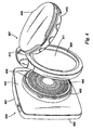
Figure 4 shows a navigation assembly according to the invention in exploded view; -
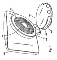
Figure 5 shows a navigation assembly according to the invention with the mount in an open configuration; and, -
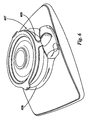
Figure 6 shows the navigation assembly offigure 5 with the mount in the closed configuration. - Preferred embodiments of the present invention will now be described with particular reference to a PND. It should be remembered, however, that the teachings of the present invention are not limited to the PNDs described but are instead universally applicable to any type of PND that is configured to execute navigation software so as to provide route planning and navigation functionality. It follows therefore that in the context of the present application, a portable navigation device is intended to include (without limitation) a portable personal computer (PC), mobile telephone or portable digital assistant (PDA)) executing route planning and navigation software.
- With the above provisos in mind,
Fig. 1 illustrates an example view of Global Positioning System (GPS), usable by navigation devices. Such systems are known and are used for a variety of purposes. In general, GPS is a satellite-radio based navigation system capable of determining continuous position, velocity, time, and in some instances direction information for an unlimited number of users. Formerly known as NAVSTAR, the GPS incorporates a plurality of satellites which orbit the earth in extremely precise orbits. Based on these precise orbits, GPS satellites can relay their location to any number of receiving units. - The GPS system is implemented when a device, specially equipped to receive GPS data, begins scanning radio frequencies for GPS satellite signals. Upon receiving a radio signal from a GPS satellite, the device determines the precise location of that satellite via one of a plurality of different conventional methods. The device will continue scanning, in most instances, for signals until it has acquired at least three different satellite signals (noting that position is not normally, but can be determined, with only two signals using other triangulation techniques). Implementing geometric triangulation, the receiver utilizes the three known positions to determine its own two-dimensional position relative to the satellites. This can be done in a known manner. Additionally, acquiring a fourth satellite signal will allow the receiving device to calculate its three dimensional position by the same geometrical calculation in a known manner. The position and velocity data can be updated in real time on a continuous basis by an unlimited number of users.
- As shown in
Figure 1 , the GPS system is denoted generally by reference numeral 100. A plurality ofsatellites 120 are in orbit about theearth 124. The orbit of eachsatellite 120 is not necessarily synchronous with the orbits ofother satellites 120 and, in fact, is likely asynchronous. AGPS receiver 140 is shown receiving spread spectrum GPS satellite signals 160 from thevarious satellites 120. - The spread spectrum signals 160, continuously transmitted from each
satellite 120, utilize a highly accurate frequency standard accomplished with an extremely accurate atomic clock. Eachsatellite 120, as part of itsdata signal transmission 160, transmits a data stream indicative of thatparticular satellite 120. It is appreciated by those skilled in the relevant art that theGPS receiver device 140 generally acquires spread spectrum GPS satellite signals 160 from at least threesatellites 120 for theGPS receiver device 140 to calculate its two-dimensional position by triangulation. Acquisition of an additional signal, resulting insignals 160 from a total of foursatellites 120, permits theGPS receiver device 140 to calculate its three-dimensional position in a known manner. -
Figure 2 is an illustrative representation of electronic components of a knownportable navigation device 200 in block component format. It should be noted that the block diagram of theportable navigation device 200 is not inclusive of all components of the portable navigation device, but is only representative of many example components. - The
portable navigation device 200 comprises a processor 210 connected to aninput device 220 and adisplay screen 240. Theinput device 220 can include a keyboard device, voice input device, touch panel and/or any other known input device utilised to input information; and thedisplay screen 240 can include any type of display screen such as an LCD display, for example. In a particularly preferred arrangement theinput device 220 anddisplay screen 240 are integrated into an integrated input and display device, including a touchpad or touchscreen input so that a user need only touch a portion of thedisplay screen 240 to select one of a plurality of display choices or to activate one of a plurality of virtual buttons. - The portable navigation device may include an
output device 260, for example an audible output device (e.g. a loudspeaker). Asoutput device 260 can produce audible information for a user of theportable navigation device 200, it is should equally be understood thatinput device 240 can include a microphone and software for receiving input voice commands as well. - In the
portable navigation device 200, processor 210 is operatively connected to and set to receive input information frominput device 220 via aconnection 225, and operatively connected to at least one ofdisplay screen 240 andoutput device 260, viaoutput connections 245, to output information thereto. Further, the processor 210 is operably coupled to amemory resource 230 viaconnection 235 and is further adapted to receive/send information from/to input/output (I/O)ports 270 viaconnection 275, wherein the I/O port 270 is connectible to an I/O device 280 external to thenavigation device 200. Thememory resource 230 comprises, for example, a volatile memory, such as a Random Access Memory (RAM) and a non-volatile memory, for example a digital memory, such as a flash memory. The external I/O device 280 may include, but is not limited to an external listening device such as an earpiece for example. The connection to I/O device 280 can further be a wired or wireless connection to any other external device such as a car stereo unit for hands-free operation and/or for voice activated operation for example, for connection to an ear piece or head phones, and/or for connection to a mobile phone for example, wherein the mobile phone connection may be used to establish a data connection between theportable navigation device 200 and the internet or any other network for example, and/or to establish a connection to a server via the internet or some other network for example. -
Fig. 2 further illustrates an operative connection between the processor 210 and an antenna/receiver 250 viaconnection 255, wherein the antenna/receiver 250 can be a GPS antenna/receiver for example. It will be understood that the antenna and receiver designated byreference numeral 250 are combined schematically for illustration, but that the antenna and receiver may be separately located components, and that the antenna may be a GPS patch antenna or helical antenna for example. - Further, it will be understood by one of ordinary skill in the art that the electronic components shown in
Fig. 2 are powered by power sources (not shown) in a conventional manner. As will be understood by one of ordinary skill in the art, different configurations of the components shown inFig. 2 are possible. For example, the components shown inFig. 2 may be in communication with one another via wired and/or wireless connections and the like. - Referring now to
Fig. 3 , theportable navigation device 200 may establish a "mobile" or telecommunications network connection with aserver 302 via a mobile device (not shown) (such as a mobile phone, PDA, and/or any device with mobile phone technology) establishing a digital connection (such as a digital connection via known Bluetooth technology for example). Thereafter, through its network service provider, the mobile device can establish a network connection (through the internet for example) with aserver 302. As such, a "mobile" network connection is established between theportable navigation device 200 and theserver 302 to provide a "real-time" or at least very "up to date" gateway for information. - The establishing of the network connection between the mobile device (via a service provider) and another device such as the
server 302, using an internet (such as the World Wide Web) for example, can be done in a known manner. This can include use of TCP/IP layered protocol for example. The mobile device can utilize any number of communication standards such as CDMA, GSM, WAN, etc. - As such, an internet connection may be utilised which is achieved via data connection, via a mobile phone or mobile phone technology within the
navigation device 200 for example. For this connection, an internet connection between theserver 302 and thenavigation device 200 is established. This can be done, for example, through a mobile phone or other mobile device and a GPRS (General Packet Radio Service)-connection (GPRS connection is a high-speed data connection for mobile devices provided by telecom operators; GPRS is a method to connect to the internet). - The
portable navigation device 200 can further complete a data connection with the mobile device, and eventually with the internet andserver 302, via existing Bluetooth technology for example, in a known manner, wherein the data protocol can utilize any number of standards, such as the GSRM, the Data Protocol Standard for the GSM standard, for example. - The
portable navigation device 200 may include its own mobile phone technology within theportable navigation device 200 itself (including an antenna for example, or optionally using the internal antenna of the portable navigation device 200). The mobile phone technology within theportable navigation device 200 can include internal components as specified above, and/or can include an insertable card (e.g. Subscriber Identity Module or SIM card), complete with necessary mobile phone technology and/or an antenna for example. As such, mobile phone technology within theportable navigation device 200 can similarly establish a network connection between theportable navigation device 200 and theserver 302, via the internet for example, in a manner similar to that of any mobile device. - For GRPS phone settings, a Bluetooth enabled portable navigation device may be used to correctly work with the ever changing spectrum of mobile phone models, manufacturers, etc., model/manufacturer specific settings may be stored on the
portable navigation device 200 for example. The data stored for this information can be updated. - In
Fig. 3 thenavigation device 200 is depicted as being in communication with theserver 302 via ageneric communications channel 318 that can be implemented by any of a number of different arrangements. Theserver 302 and aportable navigation device 200 can communicate when a connection viacommunications channel 318 is established between theserver 302 and the portable navigation device 200 (noting that such a connection can be a data connection via mobile device, a direct connection via personal computer via the internet, etc.). - The
server 302 includes, in addition to other components which may not be illustrated, aprocessor 304 operatively connected to amemory 306 and further operatively connected, via a wired orwireless connection 314, to a massdata storage device 312. Theprocessor 304 is further operatively connected totransmitter 308 andreceiver 310, to transmit and send information to and fromportable navigation device 200 viacommunications channel 318. The signals sent and received may include data, communication, and/or other propagated signals. Thetransmitter 308 andreceiver 310 may be selected or designed according to the communications requirement and communication technology used in the communication design for theportable navigation device 200. Further, it should be noted that the functions oftransmitter 308 andreceiver 310 may be combined into a signal transceiver. -
Server 302 is further connected to (or includes) amass storage device 312, noting that themass storage device 312 may be coupled to theserver 302 viacommunication link 314. Themass storage device 312 contains a store of navigation data and map information, and can again be a separate device from theserver 302 or can be incorporated into theserver 302. - The
portable navigation device 200 is adapted to communicate with theserver 302 throughcommunications channel 318, and includes processor, memory, etc. as previously described with regard toFig. 2 , as well astransmitter 320 andreceiver 322 to send and receive signals and/or data through thecommunications channel 318, noting that these devices can further be used to communicate with devices other thanserver 302. Further, thetransmitter 320 andreceiver 322 are selected or designed according to communication requirements and communication technology used in the communication design for theportable navigation device 200 and the functions of thetransmitter 320 andreceiver 322 may be combined into a single transceiver. - Software stored in
server memory 306 provides instructions for theprocessor 304 and allows theserver 302 to provide services to theportable navigation device 200. One service provided by theserver 302 involves processing requests from theportable navigation device 200 and transmitting navigation data from themass data storage 312 to theportable navigation device 200. Another service provided by theserver 302 includes processing the navigation data using various algorithms for a desired application and sending the results of these calculations to theportable navigation device 200. - The
communication channel 318 generically represents the propagating medium or path that connects theportable navigation device 200 and theserver 302. Both theserver 302 andportable navigation device 200 include a transmitter for transmitting data through the communication channel and a receiver for receiving data that has been transmitted through the communication channel. - In one illustrative arrangement, the
communication channel 318 includes telephone and computer networks. Furthermore, thecommunication channel 318 may be capable of accommodating wireless communication such as radio frequency, microwave frequency, infrared communication, etc. Additionally, thecommunication channel 318 can accommodate satellite communication. - The communication signals transmitted through the
communication channel 318 include, but are not limited to, signals as may be required or desired for given communication technology. For example, the signals may be adapted to be used in cellular communication technology such as Time Division Multiple Access (TDMA), Frequency Division Multiple Access (FDMA), Code Division Multiple Access (CDMA), Global System for Mobile Communications (GSM), etc. Both digital and analogue signals can be transmitted through thecommunication channel 318. These signals may be modulated, encrypted and/or compressed signals as may be desirable for the communication technology. - The
server 302 includes a remote server accessible by thenavigation device 200 via a wireless channel. Theserver 302 may include a network server located on a local area network (LAN), wide area network (WAN), virtual private network (VPN), etc. - The
server 302 may include a personal computer such as a desktop or laptop computer, and thecommunication channel 318 may be a cable connected between the personal computer and theportable navigation device 200. Alternatively, a personal computer may be connected between theportable navigation device 200 and theserver 302 to establish an internet connection between theserver 302 and theportable navigation device 200. Alternatively, a mobile telephone or other handheld device may establish a wireless connection to the internet, for connecting theportable navigation device 200 to theserver 302 via the internet. - The
portable navigation device 200 may be provided with information from theserver 302 via information downloads which may be periodically updated automatically or upon a user connectingportable navigation device 200 to theserver 302 and/or may be more dynamic upon a more constant or frequent connection being made between theserver 302 andportable navigation device 200 via a wireless mobile connection device and TCP/IP connection for example. For many dynamic calculations, theprocessor 304 in theserver 302 may be used to handle the bulk of the processing needs, however, processor 210 ofportable navigation device 200 can also handle much processing and calculation, oftentimes independent of a connection to aserver 302. - As indicated above in
Fig. 2 , aportable navigation device 200 includes a processor 210, aninput device 220, and adisplay screen 240. Theinput device 220 anddisplay screen 240 are integrated into an integrated input and display device to enable both input of information (via direct input, menu selection, etc.) and display of information through a touch panel screen, for example. Such a screen may be a touch input LCD screen, for example, as is well known to those of ordinary skill in the art. Further, theportable navigation device 200 can also include anyadditional input device 220 and/or any additional output device 241, such as audio input/output devices for example. - Shown in
figure 4 is anavigation assembly 400 according to the invention. Thenavigation assembly 400 comprises aportable navigation device 401 which may for example be a PND as described with reference to either offigures 2 or3 . Theportable navigation device 401 comprises ahousing 402. A portion of therear face 403 of the housing comprises aspeaker port periphery 404 which defines aspeaker port 405 as shown. Thespeaker port periphery 404 is inclined to the adjacent portion of thehousing 402 as shown. Arranged within thespeaker port 405 is aspeaker 406. - The
navigation assembly 400 further comprises afoldable mount 407. Thefoldable mount 407 comprises aconnector arm 408 and amount arm 409. The twoarms pivot point 410. Themount 407 may be folded between open and closed configurations by pivoting theconnector arm 408 about thepivot point 410 with respect to themount arm 407. - Shown in
figure 5 is themount 407 in the open configuration with theconnector arm 408 inclined to themount arm 409. Theconnector arm 408 is shown attached to thespeaker port periphery 404. In this embodiment theconnector arm 408 is snap fit into engagement with thespeaker port periphery 404. Theconnector arm 408 may be released by sharply pulling theconnector arm 408 andportable navigation device 401 apart. - An
aperture 411 extends through theconnector arm 408. Theaperture 411 is arranged such that when theconnector arm 408 is connected to thespeaker port periphery 404 theaperture 411 overlies thespeaker port 405 as shown. Sound generated by thespeaker 406 within thespeaker port 405 is therefore not distorted by theconnector arm 408. - The
mount arm 409 comprises amount arm connector 412 for connecting themount 407 to a surface such as a windscreen or dashboard. In this embodiment themount arm connector 412 comprises an elastomeric disc and a camming mechanism which draws the centre of the disc upwards to create a vacuum between the disc and the surface to which it is affixed. - Shown in
figure 6 is thefoldable mount 407 in the closed configuration with themount arm 409 adjacent to theconnector arm 408. Theconnector arm 408 and mountarm 409 are designed such that when in the closed configuration themount arm 409 fits partially within theaperture 411 in theconnector arm 408 as shown so reducing the thickness of themount 407. - When not in use the
navigation assembly 400 is typically stored as shown infigure 6 with theportable navigation device 401 connected to theconnector arm 408 of themount 407, themount 407 being folded in the closed configuration. In this configuration thenavigation assembly 400 is sufficiently compact that it can easily be stored in a pocket or briefcase if required. When it is desired to use thenavigation assembly 400 themount 407 is unfolded to the open configuration. The elastomeric disc is pushed against a surface and the camming mechanism then rotated, deforming the disk and fixing themount 407 in place. When the user has finished using thenavigation assembly 400 the camming mechanism is rotated in the opposite direction freeing the elastomeric disk from the surface to which it is attached. Themount 407 is then folded back to the closed configuration. - In the above embodiment the
connector arm 408 snap fits into engagement with thespeaker port periphery 404. In alternative embodiments of the invention other types of connection to thespeaker port periphery 404 are possible. For example theconnector arm 408 andPND 401 may be screwed together by means of corresponding threads on theconnector arm 408 andspeaker port periphery 404. In an alternative embodiment there may be a simple interference fit betweenconnector arm 408 andspeaker port periphery 404. - In an alternative embodiment of the invention the
mount arm 409 comprises a simple elastomeric disk which is pushed into contact with a surface. - In the embodiment described with reference to
figure 5 thespeaker port 405 is an aperture in thehousing 402 of theportable navigation device 401. In an alternative embodiment thespeaker port 405 comprises a plurality of apertures defining a mesh. In this embodiment aspeaker 406 is contained within thePND 401 behind the mesh. - In an alternative embodiment of the invention the
connector arm 408 extends only a portion of the way around the periphery of thespeaker port 405. If thespeaker port 405 is circular then theconnector arm 408 has a uniform curvature. If thespeaker port 405 is other than circular, for example oval, square or oblong then the curvature of theconnector arm 408 varies along its length to match a portion of the periphery of thespeaker port 405. In each case theconnector arm 408 is dimensioned such that when it is connected to thespeaker port periphery 404 at least a portion of thespeaker port 405 is not covered by theconnector arm 408.
Claims (7)
- A navigation (400) assembly comprising
a portable navigation device (401) comprising a housing (402), the housing comprising a speaker port (405) defined by a speaker port periphery (404) which inclined to the housing of which it forms part; and,
a mount (407) comprising a connector arm (408), the connector arm being adapted to be connected to the portable navigation device,
characterised in that the connection between the connector arm and the navigation device is achieved by means of the connector arm being of a shape which is complementary with, and which engages with, at least a portion of the speaker port periphery so as to be substantially peripheral to the speaker port and such that at least a portion of said speaker port remains uncovered thereby. - A navigation assembly (400) as claimed in claim 1, wherein the connector arm (408) defines an aperture (411), the aperture being arranged such that it overlies at least a portion of the speaker port (405) when the connector arm is connected to the speaker port periphery (404).
- A navigation assembly (400) as claimed in any one of claims 1 to 2, wherein the speaker port (405) comprises an aperture in the housing (402), the portable navigation device (401) further comprising a speaker (406) within the speaker port.
- A navigation assembly (400) as claimed in any one of claims 1 to 3, wherein the speaker port (405) comprises a plurality of apertures defining a mesh, the portable navigation device (401) further comprising a speaker (406) within the housing behind the mesh.
- A navigation assembly (400) as claimed in any one of claims 1 to 4, wherein the mount (407) further comprises a mount arm (409) for connection to a surface, the mount arm being pivotally connected to the connector arm (408) such that the mount can be folded from an open configuration with the connector arm inclined to the mount arm to a closed configuration with the mount arm adjacent to the connector arm.
- A navigation assembly (400) as claimed in claim 5, when dependent on claim 2, wherein the mount arm (409) is adapted to be at least partially received in the aperture (411) in the connector arm (408) when the mount is in the closed configuration.
- A mount (407) adapted for use in the navigation assembly (400) of any preceding claim.
Applications Claiming Priority (2)
| Application Number | Priority Date | Filing Date | Title |
|---|---|---|---|
| US657708P | 2008-01-22 | 2008-01-22 | |
| PCT/EP2009/050414 WO2009092660A2 (en) | 2008-01-22 | 2009-01-15 | A navigation assembly, a foldable mount and a navigation assembly including such a mount. |
Publications (2)
| Publication Number | Publication Date |
|---|---|
| EP2252483A2 EP2252483A2 (en) | 2010-11-24 |
| EP2252483B1 true EP2252483B1 (en) | 2012-07-04 |
Family
ID=40901474
Family Applications (1)
| Application Number | Title | Priority Date | Filing Date |
|---|---|---|---|
| EP09704191A Active EP2252483B1 (en) | 2008-01-22 | 2009-01-15 | A navigation assembly, a foldable mount and a navigation assembly including such a mount |
Country Status (9)
| Country | Link |
|---|---|
| US (1) | US8814116B2 (en) |
| EP (1) | EP2252483B1 (en) |
| JP (1) | JP2011512516A (en) |
| CN (1) | CN101909941B (en) |
| AU (1) | AU2009207768B2 (en) |
| CA (1) | CA2711941A1 (en) |
| RU (1) | RU2490149C2 (en) |
| TW (1) | TW200936986A (en) |
| WO (1) | WO2009092660A2 (en) |
Families Citing this family (5)
| Publication number | Priority date | Publication date | Assignee | Title |
|---|---|---|---|---|
| WO2011026517A1 (en) * | 2009-09-03 | 2011-03-10 | Tomtom International B.V. | Mount apparatus, navigation device assembly and chassis |
| WO2011098094A1 (en) | 2010-02-09 | 2011-08-18 | Valeo Schalter Und Sensoren Gmbh | Holding device for a portable communication device, driver assistance system for a vehicle, vehicle with a vehicle assistance system, and method for providing driver assistance |
| RU2530725C2 (en) * | 2013-01-10 | 2014-10-10 | Открытое акционерное общество "Завод им. В.А. Дегтярева" | Bracket |
| US9326053B2 (en) * | 2014-03-10 | 2016-04-26 | Ford Global Technologies, Llc | Flat panel speaker assembly integrated with vehicle trim |
| CN105292003B (en) * | 2014-05-30 | 2018-01-02 | 深圳市赛格导航技术有限公司 | A kind of navigation screen fixes back splint |
Family Cites Families (49)
| Publication number | Priority date | Publication date | Assignee | Title |
|---|---|---|---|---|
| US4836482A (en) * | 1986-08-11 | 1989-06-06 | Detroit Bracket Company, Inc. | Hinged support bracket for a radar detector or like device |
| US4807425A (en) * | 1987-11-30 | 1989-02-28 | Abrams Robert S | Method and device for opening and closing vials |
| JPH0339952U (en) * | 1989-08-29 | 1991-04-17 | ||
| DE20313215U1 (en) * | 2003-08-25 | 2003-10-16 | Richter Herbert | holder |
| US5456294A (en) * | 1993-02-05 | 1995-10-10 | Innostar, Inc. | Nonspill bottled water replacement system with a shielded disposable cap |
| US5604813A (en) * | 1994-05-02 | 1997-02-18 | Noise Cancellation Technologies, Inc. | Industrial headset |
| JP3260589B2 (en) | 1995-05-23 | 2002-02-25 | シャープ株式会社 | Display mounting device |
| JP3039952U (en) | 1996-11-25 | 1997-08-05 | 有限会社テックメック | Floatant bottle for fly fishing |
| US6663064B1 (en) * | 1999-12-01 | 2003-12-16 | Garmin Corporation | Multi-position articulating mounting apparatus for an electronic device |
| JP3341066B2 (en) * | 1999-05-20 | 2002-11-05 | 株式会社ナナオ | Vertical rotation support mechanism for video monitor |
| WO2001029514A1 (en) * | 1999-10-19 | 2001-04-26 | Magellan Dis, Inc. | Portable vehicle navigation system |
| ATE330818T1 (en) * | 1999-11-24 | 2006-07-15 | Donnelly Corp | REARVIEW MIRROR WITH USEFUL FUNCTION |
| US20030180088A1 (en) * | 2000-09-02 | 2003-09-25 | Camevali Jeffrey D. | Flexible electronic mount apparatus |
| US6545637B1 (en) * | 2001-12-20 | 2003-04-08 | Garmin, Ltd. | Systems and methods for a navigational device with improved route calculation capabilities |
| US7184886B1 (en) * | 2001-12-21 | 2007-02-27 | Garmin Ltd. | Navigation system, method and device with detour algorithm |
| US7299129B2 (en) * | 2002-04-02 | 2007-11-20 | Garmin Ltd. | Portable navigation device with releasable antenna |
| AU2003237424A1 (en) * | 2002-06-06 | 2003-12-22 | Donnelly Corporation | Interior rearview mirror system with compass |
| US6779765B2 (en) * | 2002-11-26 | 2004-08-24 | Beltronics Usa Inc. | Mounting device for a radar detector |
| JP2004217143A (en) * | 2003-01-17 | 2004-08-05 | Sanyo Electric Co Ltd | Support stand device of apparatus |
| US6966533B1 (en) * | 2003-05-05 | 2005-11-22 | Garmin Ltd. | Mounting apparatus for an electronic device |
| US6913232B2 (en) * | 2003-06-20 | 2005-07-05 | Herbert Richter | Article support system |
| KR100753607B1 (en) | 2003-10-27 | 2007-08-30 | 삼성전자주식회사 | Display Apparatus |
| US7412267B2 (en) * | 2003-10-30 | 2008-08-12 | Sony Ericsson Mobile Communications Ab | Mobile device with a combination attachment and acoustic port |
| JP2005221810A (en) * | 2004-02-06 | 2005-08-18 | Matsushita Electric Ind Co Ltd | Liquid crystal display |
| GB0405794D0 (en) * | 2004-03-15 | 2004-04-21 | Tomtom Bv | Dock for a portable navigation device |
| US7526103B2 (en) * | 2004-04-15 | 2009-04-28 | Donnelly Corporation | Imaging system for vehicle |
| CN2709253Y (en) * | 2004-06-08 | 2005-07-13 | 徐金鹏 | Vehicle display device |
| KR20060092971A (en) * | 2004-10-26 | 2006-08-23 | 리히터 하랄트 | Modular apparatus holder with multipurpose intermediate support member for supporting minicomputer, cell phone and similar apparatus |
| US7515709B2 (en) * | 2004-10-26 | 2009-04-07 | Harald Richter | Modular apparatus holder with multipurpose intermediate support member for supporting minicomputers, cell phones and similar apparatus |
| US7219867B2 (en) * | 2005-07-14 | 2007-05-22 | Garmin Ltd. | Mount assembly for electronic devices |
| US20070016360A1 (en) * | 2005-07-14 | 2007-01-18 | Lee Choy W | Navigational device with improved user interface |
| JP4718927B2 (en) * | 2005-07-29 | 2011-07-06 | パイオニア株式会社 | Speaker device |
| DE502005000911D1 (en) * | 2005-10-06 | 2007-08-02 | Harald Richter | Gear tray with squeegee and column in half-shell construction |
| USD552970S1 (en) * | 2005-12-05 | 2007-10-16 | Paul Brassard | Suction mount |
| US7606660B2 (en) * | 2005-12-31 | 2009-10-20 | Alpine Electronics, Inc. | In-vehicle navigation system with removable navigation unit |
| CN2905558Y (en) * | 2006-03-29 | 2007-05-30 | 宁波绅乐电子有限公司 | Vehicular ceiling type display |
| RU58828U1 (en) * | 2006-04-28 | 2006-11-27 | ООО "АвтоВизус" | UNIVERSAL VEHICLE TELECOMMUNICATION DEVICE |
| GB2440339A (en) * | 2006-07-21 | 2008-01-30 | Artform Internat Ltd | Means for securing an electrical device |
| TWM316200U (en) * | 2007-01-15 | 2007-08-01 | Lite On Technology Corp | A holder for receiving an electronic device |
| JP5018175B2 (en) * | 2007-03-28 | 2012-09-05 | ソニー株式会社 | Electronics |
| DE202007005661U1 (en) * | 2007-04-19 | 2007-07-05 | Buchhalter, Thomas | Implement holder has mounting plate is fastened by mounting plate in close proximity of driver on instrument panel |
| JP4630327B2 (en) | 2007-05-03 | 2011-02-09 | 日本ビクター株式会社 | Navigation device |
| DE202007007021U1 (en) | 2007-05-16 | 2007-09-27 | COMART Corporation, Sandian City | Holder for digital device |
| US20090127411A1 (en) * | 2007-11-20 | 2009-05-21 | Antonio Aguilar | Structure and mechanism of windshield mount and pedestal for portable electronics device |
| USD590835S1 (en) * | 2007-12-27 | 2009-04-21 | Harald Richter | Apparatus support device holder |
| US8186642B2 (en) * | 2008-12-23 | 2012-05-29 | John Weiss-Vons | Portable device accessory |
| TWI340620B (en) * | 2009-01-20 | 2011-04-11 | Htc Corp | Clamping apparatus |
| US8622359B2 (en) * | 2011-06-15 | 2014-01-07 | Jeffrey D. Carnevali | Mounting for a portable device |
| US8544161B2 (en) * | 2011-06-15 | 2013-10-01 | Jeffrey D. Carnevali | Method for mounting a portable device |
-
2009
- 2009-01-15 CN CN200980102171.2A patent/CN101909941B/en not_active Expired - Fee Related
- 2009-01-15 AU AU2009207768A patent/AU2009207768B2/en not_active Ceased
- 2009-01-15 CA CA2711941A patent/CA2711941A1/en not_active Abandoned
- 2009-01-15 EP EP09704191A patent/EP2252483B1/en active Active
- 2009-01-15 JP JP2010542624A patent/JP2011512516A/en active Pending
- 2009-01-15 US US12/735,321 patent/US8814116B2/en active Active
- 2009-01-15 WO PCT/EP2009/050414 patent/WO2009092660A2/en active Application Filing
- 2009-01-15 RU RU2010134921/11A patent/RU2490149C2/en not_active IP Right Cessation
- 2009-01-22 TW TW98102664A patent/TW200936986A/en unknown
Also Published As
| Publication number | Publication date |
|---|---|
| US20100280746A1 (en) | 2010-11-04 |
| WO2009092660A2 (en) | 2009-07-30 |
| EP2252483A2 (en) | 2010-11-24 |
| CN101909941A (en) | 2010-12-08 |
| JP2011512516A (en) | 2011-04-21 |
| CN101909941B (en) | 2014-12-10 |
| WO2009092660A3 (en) | 2009-11-26 |
| RU2490149C2 (en) | 2013-08-20 |
| AU2009207768B2 (en) | 2014-09-04 |
| US8814116B2 (en) | 2014-08-26 |
| RU2010134921A (en) | 2012-02-27 |
| TW200936986A (en) | 2009-09-01 |
| CA2711941A1 (en) | 2009-07-30 |
| AU2009207768A1 (en) | 2009-07-30 |
Similar Documents
| Publication | Publication Date | Title |
|---|---|---|
| US10161755B2 (en) | Navigation device and method | |
| US8825357B2 (en) | Navigation device and method | |
| US20120221247A1 (en) | Navigation device & method | |
| US9037395B2 (en) | Mobile device that operates differently in different regions | |
| US20090177390A1 (en) | Navigation device and method for updating a digital map | |
| WO2010040386A1 (en) | Navigation apparatus and method of determining a route therefor | |
| EP2252483B1 (en) | A navigation assembly, a foldable mount and a navigation assembly including such a mount | |
| WO2010076045A1 (en) | Timed route navigation device | |
| US8843310B2 (en) | Navigation device communications with points of interest and update method | |
| US20120221242A1 (en) | Navigation device and a method of operation of a navigation device | |
| WO2010081538A2 (en) | Navigation device & method | |
| WO2009132679A1 (en) | Navigation device & method | |
| WO2009080069A1 (en) | Method and apparatus for updating a digital map | |
| WO2010040382A1 (en) | Navigation apparatus and method for use therein | |
| WO2009132680A1 (en) | Navigation device and method |
Legal Events
| Date | Code | Title | Description |
|---|---|---|---|
| PUAI | Public reference made under article 153(3) epc to a published international application that has entered the european phase |
Free format text: ORIGINAL CODE: 0009012 |
|
| 17P | Request for examination filed |
Effective date: 20100728 |
|
| AK | Designated contracting states |
Kind code of ref document: A2 Designated state(s): AT BE BG CH CY CZ DE DK EE ES FI FR GB GR HR HU IE IS IT LI LT LU LV MC MK MT NL NO PL PT RO SE SI SK TR |
|
| GRAP | Despatch of communication of intention to grant a patent |
Free format text: ORIGINAL CODE: EPIDOSNIGR1 |
|
| DAX | Request for extension of the european patent (deleted) | ||
| GRAS | Grant fee paid |
Free format text: ORIGINAL CODE: EPIDOSNIGR3 |
|
| RAP1 | Party data changed (applicant data changed or rights of an application transferred) |
Owner name: TOMTOM INTERNATIONAL B.V. |
|
| GRAA | (expected) grant |
Free format text: ORIGINAL CODE: 0009210 |
|
| AK | Designated contracting states |
Kind code of ref document: B1 Designated state(s): AT BE BG CH CY CZ DE DK EE ES FI FR GB GR HR HU IE IS IT LI LT LU LV MC MK MT NL NO PL PT RO SE SI SK TR |
|
| REG | Reference to a national code |
Ref country code: GB Ref legal event code: FG4D |
|
| REG | Reference to a national code |
Ref country code: CH Ref legal event code: EP |
|
| REG | Reference to a national code |
Ref country code: AT Ref legal event code: REF Ref document number: 565029 Country of ref document: AT Kind code of ref document: T Effective date: 20120715 |
|
| REG | Reference to a national code |
Ref country code: IE Ref legal event code: FG4D |
|
| REG | Reference to a national code |
Ref country code: NL Ref legal event code: T3 |
|
| REG | Reference to a national code |
Ref country code: DE Ref legal event code: R096 Ref document number: 602009008045 Country of ref document: DE Effective date: 20120830 |
|
| REG | Reference to a national code |
Ref country code: AT Ref legal event code: MK05 Ref document number: 565029 Country of ref document: AT Kind code of ref document: T Effective date: 20120704 |
|
| PG25 | Lapsed in a contracting state [announced via postgrant information from national office to epo] |
Ref country code: SI Free format text: LAPSE BECAUSE OF FAILURE TO SUBMIT A TRANSLATION OF THE DESCRIPTION OR TO PAY THE FEE WITHIN THE PRESCRIBED TIME-LIMIT Effective date: 20120704 |
|
| REG | Reference to a national code |
Ref country code: LT Ref legal event code: MG4D Effective date: 20120704 |
|
| PG25 | Lapsed in a contracting state [announced via postgrant information from national office to epo] |
Ref country code: NO Free format text: LAPSE BECAUSE OF FAILURE TO SUBMIT A TRANSLATION OF THE DESCRIPTION OR TO PAY THE FEE WITHIN THE PRESCRIBED TIME-LIMIT Effective date: 20121004 Ref country code: AT Free format text: LAPSE BECAUSE OF FAILURE TO SUBMIT A TRANSLATION OF THE DESCRIPTION OR TO PAY THE FEE WITHIN THE PRESCRIBED TIME-LIMIT Effective date: 20120704 Ref country code: HR Free format text: LAPSE BECAUSE OF FAILURE TO SUBMIT A TRANSLATION OF THE DESCRIPTION OR TO PAY THE FEE WITHIN THE PRESCRIBED TIME-LIMIT Effective date: 20120704 Ref country code: CY Free format text: LAPSE BECAUSE OF FAILURE TO SUBMIT A TRANSLATION OF THE DESCRIPTION OR TO PAY THE FEE WITHIN THE PRESCRIBED TIME-LIMIT Effective date: 20120704 Ref country code: BE Free format text: LAPSE BECAUSE OF FAILURE TO SUBMIT A TRANSLATION OF THE DESCRIPTION OR TO PAY THE FEE WITHIN THE PRESCRIBED TIME-LIMIT Effective date: 20120704 Ref country code: IS Free format text: LAPSE BECAUSE OF FAILURE TO SUBMIT A TRANSLATION OF THE DESCRIPTION OR TO PAY THE FEE WITHIN THE PRESCRIBED TIME-LIMIT Effective date: 20121104 Ref country code: LT Free format text: LAPSE BECAUSE OF FAILURE TO SUBMIT A TRANSLATION OF THE DESCRIPTION OR TO PAY THE FEE WITHIN THE PRESCRIBED TIME-LIMIT Effective date: 20120704 Ref country code: FI Free format text: LAPSE BECAUSE OF FAILURE TO SUBMIT A TRANSLATION OF THE DESCRIPTION OR TO PAY THE FEE WITHIN THE PRESCRIBED TIME-LIMIT Effective date: 20120704 |
|
| PG25 | Lapsed in a contracting state [announced via postgrant information from national office to epo] |
Ref country code: LV Free format text: LAPSE BECAUSE OF FAILURE TO SUBMIT A TRANSLATION OF THE DESCRIPTION OR TO PAY THE FEE WITHIN THE PRESCRIBED TIME-LIMIT Effective date: 20120704 Ref country code: GR Free format text: LAPSE BECAUSE OF FAILURE TO SUBMIT A TRANSLATION OF THE DESCRIPTION OR TO PAY THE FEE WITHIN THE PRESCRIBED TIME-LIMIT Effective date: 20121005 Ref country code: SE Free format text: LAPSE BECAUSE OF FAILURE TO SUBMIT A TRANSLATION OF THE DESCRIPTION OR TO PAY THE FEE WITHIN THE PRESCRIBED TIME-LIMIT Effective date: 20120704 Ref country code: PL Free format text: LAPSE BECAUSE OF FAILURE TO SUBMIT A TRANSLATION OF THE DESCRIPTION OR TO PAY THE FEE WITHIN THE PRESCRIBED TIME-LIMIT Effective date: 20120704 Ref country code: PT Free format text: LAPSE BECAUSE OF FAILURE TO SUBMIT A TRANSLATION OF THE DESCRIPTION OR TO PAY THE FEE WITHIN THE PRESCRIBED TIME-LIMIT Effective date: 20121105 |
|
| PG25 | Lapsed in a contracting state [announced via postgrant information from national office to epo] |
Ref country code: RO Free format text: LAPSE BECAUSE OF FAILURE TO SUBMIT A TRANSLATION OF THE DESCRIPTION OR TO PAY THE FEE WITHIN THE PRESCRIBED TIME-LIMIT Effective date: 20120704 Ref country code: ES Free format text: LAPSE BECAUSE OF FAILURE TO SUBMIT A TRANSLATION OF THE DESCRIPTION OR TO PAY THE FEE WITHIN THE PRESCRIBED TIME-LIMIT Effective date: 20121015 Ref country code: EE Free format text: LAPSE BECAUSE OF FAILURE TO SUBMIT A TRANSLATION OF THE DESCRIPTION OR TO PAY THE FEE WITHIN THE PRESCRIBED TIME-LIMIT Effective date: 20120704 Ref country code: CZ Free format text: LAPSE BECAUSE OF FAILURE TO SUBMIT A TRANSLATION OF THE DESCRIPTION OR TO PAY THE FEE WITHIN THE PRESCRIBED TIME-LIMIT Effective date: 20120704 Ref country code: DK Free format text: LAPSE BECAUSE OF FAILURE TO SUBMIT A TRANSLATION OF THE DESCRIPTION OR TO PAY THE FEE WITHIN THE PRESCRIBED TIME-LIMIT Effective date: 20120704 |
|
| PLBE | No opposition filed within time limit |
Free format text: ORIGINAL CODE: 0009261 |
|
| STAA | Information on the status of an ep patent application or granted ep patent |
Free format text: STATUS: NO OPPOSITION FILED WITHIN TIME LIMIT |
|
| PG25 | Lapsed in a contracting state [announced via postgrant information from national office to epo] |
Ref country code: SK Free format text: LAPSE BECAUSE OF FAILURE TO SUBMIT A TRANSLATION OF THE DESCRIPTION OR TO PAY THE FEE WITHIN THE PRESCRIBED TIME-LIMIT Effective date: 20120704 Ref country code: IT Free format text: LAPSE BECAUSE OF FAILURE TO SUBMIT A TRANSLATION OF THE DESCRIPTION OR TO PAY THE FEE WITHIN THE PRESCRIBED TIME-LIMIT Effective date: 20120704 |
|
| 26N | No opposition filed |
Effective date: 20130405 |
|
| PG25 | Lapsed in a contracting state [announced via postgrant information from national office to epo] |
Ref country code: BG Free format text: LAPSE BECAUSE OF FAILURE TO SUBMIT A TRANSLATION OF THE DESCRIPTION OR TO PAY THE FEE WITHIN THE PRESCRIBED TIME-LIMIT Effective date: 20121004 |
|
| REG | Reference to a national code |
Ref country code: DE Ref legal event code: R097 Ref document number: 602009008045 Country of ref document: DE Effective date: 20130405 |
|
| PG25 | Lapsed in a contracting state [announced via postgrant information from national office to epo] |
Ref country code: MC Free format text: LAPSE BECAUSE OF NON-PAYMENT OF DUE FEES Effective date: 20130131 |
|
| REG | Reference to a national code |
Ref country code: CH Ref legal event code: PL |
|
| REG | Reference to a national code |
Ref country code: IE Ref legal event code: MM4A |
|
| PG25 | Lapsed in a contracting state [announced via postgrant information from national office to epo] |
Ref country code: LI Free format text: LAPSE BECAUSE OF NON-PAYMENT OF DUE FEES Effective date: 20130131 Ref country code: CH Free format text: LAPSE BECAUSE OF NON-PAYMENT OF DUE FEES Effective date: 20130131 |
|
| PG25 | Lapsed in a contracting state [announced via postgrant information from national office to epo] |
Ref country code: IE Free format text: LAPSE BECAUSE OF NON-PAYMENT OF DUE FEES Effective date: 20130115 |
|
| PG25 | Lapsed in a contracting state [announced via postgrant information from national office to epo] |
Ref country code: MT Free format text: LAPSE BECAUSE OF FAILURE TO SUBMIT A TRANSLATION OF THE DESCRIPTION OR TO PAY THE FEE WITHIN THE PRESCRIBED TIME-LIMIT Effective date: 20120704 |
|
| PG25 | Lapsed in a contracting state [announced via postgrant information from national office to epo] |
Ref country code: TR Free format text: LAPSE BECAUSE OF FAILURE TO SUBMIT A TRANSLATION OF THE DESCRIPTION OR TO PAY THE FEE WITHIN THE PRESCRIBED TIME-LIMIT Effective date: 20120704 |
|
| PG25 | Lapsed in a contracting state [announced via postgrant information from national office to epo] |
Ref country code: LU Free format text: LAPSE BECAUSE OF NON-PAYMENT OF DUE FEES Effective date: 20130115 Ref country code: HU Free format text: LAPSE BECAUSE OF FAILURE TO SUBMIT A TRANSLATION OF THE DESCRIPTION OR TO PAY THE FEE WITHIN THE PRESCRIBED TIME-LIMIT; INVALID AB INITIO Effective date: 20090115 Ref country code: MK Free format text: LAPSE BECAUSE OF FAILURE TO SUBMIT A TRANSLATION OF THE DESCRIPTION OR TO PAY THE FEE WITHIN THE PRESCRIBED TIME-LIMIT Effective date: 20120704 |
|
| REG | Reference to a national code |
Ref country code: FR Ref legal event code: PLFP Year of fee payment: 8 |
|
| REG | Reference to a national code |
Ref country code: FR Ref legal event code: PLFP Year of fee payment: 9 |
|
| REG | Reference to a national code |
Ref country code: FR Ref legal event code: PLFP Year of fee payment: 10 |
|
| PGFP | Annual fee paid to national office [announced via postgrant information from national office to epo] |
Ref country code: NL Payment date: 20221220 Year of fee payment: 15 Ref country code: GB Payment date: 20221201 Year of fee payment: 15 Ref country code: FR Payment date: 20221221 Year of fee payment: 15 |
|
| PGFP | Annual fee paid to national office [announced via postgrant information from national office to epo] |
Ref country code: DE Payment date: 20221207 Year of fee payment: 15 |