EP2252199B1 - Snapshot spectral imaging of the eye - Google Patents
Snapshot spectral imaging of the eye Download PDFInfo
- Publication number
- EP2252199B1 EP2252199B1 EP09716310.9A EP09716310A EP2252199B1 EP 2252199 B1 EP2252199 B1 EP 2252199B1 EP 09716310 A EP09716310 A EP 09716310A EP 2252199 B1 EP2252199 B1 EP 2252199B1
- Authority
- EP
- European Patent Office
- Prior art keywords
- spectral
- array
- sensor array
- filter
- filter array
- Prior art date
- Legal status (The legal status is an assumption and is not a legal conclusion. Google has not performed a legal analysis and makes no representation as to the accuracy of the status listed.)
- Active
Links
- 238000000701 chemical imaging Methods 0.000 title claims description 20
- 230000003595 spectral effect Effects 0.000 claims description 70
- 238000000034 method Methods 0.000 claims description 58
- 230000003287 optical effect Effects 0.000 claims description 34
- 230000002207 retinal effect Effects 0.000 claims description 25
- 238000003384 imaging method Methods 0.000 claims description 22
- QVGXLLKOCUKJST-UHFFFAOYSA-N atomic oxygen Chemical compound [O] QVGXLLKOCUKJST-UHFFFAOYSA-N 0.000 claims description 12
- 229910052760 oxygen Inorganic materials 0.000 claims description 12
- 239000001301 oxygen Substances 0.000 claims description 12
- 230000002911 mydriatic effect Effects 0.000 claims description 11
- 239000008280 blood Substances 0.000 claims description 9
- 210000004369 blood Anatomy 0.000 claims description 9
- 230000004256 retinal image Effects 0.000 claims description 4
- 239000010409 thin film Substances 0.000 claims description 4
- 230000010344 pupil dilation Effects 0.000 claims description 2
- 239000006059 cover glass Substances 0.000 claims 2
- 210000001508 eye Anatomy 0.000 description 31
- 210000001525 retina Anatomy 0.000 description 31
- 238000001228 spectrum Methods 0.000 description 22
- 102000001554 Hemoglobins Human genes 0.000 description 20
- 108010054147 Hemoglobins Proteins 0.000 description 20
- 238000003491 array Methods 0.000 description 11
- 238000005259 measurement Methods 0.000 description 11
- 230000008569 process Effects 0.000 description 10
- 210000001519 tissue Anatomy 0.000 description 10
- 238000005286 illumination Methods 0.000 description 8
- 238000002496 oximetry Methods 0.000 description 8
- 239000000758 substrate Substances 0.000 description 8
- 238000000576 coating method Methods 0.000 description 7
- 238000012216 screening Methods 0.000 description 7
- 230000008901 benefit Effects 0.000 description 6
- 229920002120 photoresistant polymer Polymers 0.000 description 6
- 210000001210 retinal vessel Anatomy 0.000 description 5
- 210000003462 vein Anatomy 0.000 description 5
- 206010012689 Diabetic retinopathy Diseases 0.000 description 4
- 210000001367 artery Anatomy 0.000 description 4
- 238000004364 calculation method Methods 0.000 description 4
- 201000010099 disease Diseases 0.000 description 4
- 208000037265 diseases, disorders, signs and symptoms Diseases 0.000 description 4
- 238000005516 engineering process Methods 0.000 description 4
- 230000004424 eye movement Effects 0.000 description 4
- 230000033001 locomotion Effects 0.000 description 4
- 210000001747 pupil Anatomy 0.000 description 4
- 230000004044 response Effects 0.000 description 4
- 230000035945 sensitivity Effects 0.000 description 4
- 238000010521 absorption reaction Methods 0.000 description 3
- 238000000862 absorption spectrum Methods 0.000 description 3
- 238000004458 analytical method Methods 0.000 description 3
- 210000004204 blood vessel Anatomy 0.000 description 3
- 239000011248 coating agent Substances 0.000 description 3
- 238000012937 correction Methods 0.000 description 3
- 238000001514 detection method Methods 0.000 description 3
- 238000003745 diagnosis Methods 0.000 description 3
- 230000000694 effects Effects 0.000 description 3
- 238000012014 optical coherence tomography Methods 0.000 description 3
- 238000006213 oxygenation reaction Methods 0.000 description 3
- 230000001766 physiological effect Effects 0.000 description 3
- 206010065042 Immune reconstitution inflammatory syndrome Diseases 0.000 description 2
- 208000014139 Retinal vascular disease Diseases 0.000 description 2
- 239000002318 adhesion promoter Substances 0.000 description 2
- 230000008033 biological extinction Effects 0.000 description 2
- 230000005540 biological transmission Effects 0.000 description 2
- 210000005252 bulbus oculi Anatomy 0.000 description 2
- 238000013329 compounding Methods 0.000 description 2
- 238000000151 deposition Methods 0.000 description 2
- 230000008021 deposition Effects 0.000 description 2
- 238000011161 development Methods 0.000 description 2
- 206010012601 diabetes mellitus Diseases 0.000 description 2
- 230000007613 environmental effect Effects 0.000 description 2
- 229910052736 halogen Inorganic materials 0.000 description 2
- 150000002367 halogens Chemical class 0.000 description 2
- 230000006872 improvement Effects 0.000 description 2
- 238000001727 in vivo Methods 0.000 description 2
- 239000004973 liquid crystal related substance Substances 0.000 description 2
- 230000000737 periodic effect Effects 0.000 description 2
- 230000035479 physiological effects, processes and functions Effects 0.000 description 2
- 238000012545 processing Methods 0.000 description 2
- 210000003583 retinal pigment epithelium Anatomy 0.000 description 2
- 239000000523 sample Substances 0.000 description 2
- 238000005070 sampling Methods 0.000 description 2
- 238000002798 spectrophotometry method Methods 0.000 description 2
- 201000004569 Blindness Diseases 0.000 description 1
- 241000579895 Chlorostilbon Species 0.000 description 1
- 208000034656 Contusions Diseases 0.000 description 1
- 206010012667 Diabetic glaucoma Diseases 0.000 description 1
- 206010015150 Erythema Diseases 0.000 description 1
- 208000010412 Glaucoma Diseases 0.000 description 1
- 208000017442 Retinal disease Diseases 0.000 description 1
- 230000003213 activating effect Effects 0.000 description 1
- 230000006978 adaptation Effects 0.000 description 1
- 206010064930 age-related macular degeneration Diseases 0.000 description 1
- 238000013459 approach Methods 0.000 description 1
- 230000004087 circulation Effects 0.000 description 1
- 239000011247 coating layer Substances 0.000 description 1
- 239000003086 colorant Substances 0.000 description 1
- 238000002591 computed tomography Methods 0.000 description 1
- 238000004590 computer program Methods 0.000 description 1
- 230000001419 dependent effect Effects 0.000 description 1
- 230000000916 dilatatory effect Effects 0.000 description 1
- 208000029436 dilated pupil Diseases 0.000 description 1
- 230000010339 dilation Effects 0.000 description 1
- 229910052876 emerald Inorganic materials 0.000 description 1
- 239000010976 emerald Substances 0.000 description 1
- 230000002708 enhancing effect Effects 0.000 description 1
- 231100000321 erythema Toxicity 0.000 description 1
- 238000011156 evaluation Methods 0.000 description 1
- 238000002474 experimental method Methods 0.000 description 1
- 239000000284 extract Substances 0.000 description 1
- 238000001914 filtration Methods 0.000 description 1
- 210000003128 head Anatomy 0.000 description 1
- 238000010348 incorporation Methods 0.000 description 1
- 238000011835 investigation Methods 0.000 description 1
- 230000031700 light absorption Effects 0.000 description 1
- 208000002780 macular degeneration Diseases 0.000 description 1
- 238000004519 manufacturing process Methods 0.000 description 1
- 238000013507 mapping Methods 0.000 description 1
- 230000002503 metabolic effect Effects 0.000 description 1
- 239000002184 metal Substances 0.000 description 1
- 238000001393 microlithography Methods 0.000 description 1
- 239000000203 mixture Substances 0.000 description 1
- 238000012544 monitoring process Methods 0.000 description 1
- 230000006855 networking Effects 0.000 description 1
- 230000004386 ocular blood flow Effects 0.000 description 1
- 239000000123 paper Substances 0.000 description 1
- 230000001575 pathological effect Effects 0.000 description 1
- 238000000059 patterning Methods 0.000 description 1
- 238000003825 pressing Methods 0.000 description 1
- 230000009467 reduction Effects 0.000 description 1
- 238000002310 reflectometry Methods 0.000 description 1
- 238000011160 research Methods 0.000 description 1
- 210000001927 retinal artery Anatomy 0.000 description 1
- 210000001957 retinal vein Anatomy 0.000 description 1
- 238000005096 rolling process Methods 0.000 description 1
- 239000002904 solvent Substances 0.000 description 1
- 238000010183 spectrum analysis Methods 0.000 description 1
- 239000000126 substance Substances 0.000 description 1
- 230000002123 temporal effect Effects 0.000 description 1
- 238000012360 testing method Methods 0.000 description 1
- 238000007736 thin film deposition technique Methods 0.000 description 1
- 238000001771 vacuum deposition Methods 0.000 description 1
- 230000000007 visual effect Effects 0.000 description 1
- 229910052724 xenon Inorganic materials 0.000 description 1
- FHNFHKCVQCLJFQ-UHFFFAOYSA-N xenon atom Chemical compound [Xe] FHNFHKCVQCLJFQ-UHFFFAOYSA-N 0.000 description 1
Images


Classifications
-
- G—PHYSICS
- G01—MEASURING; TESTING
- G01J—MEASUREMENT OF INTENSITY, VELOCITY, SPECTRAL CONTENT, POLARISATION, PHASE OR PULSE CHARACTERISTICS OF INFRARED, VISIBLE OR ULTRAVIOLET LIGHT; COLORIMETRY; RADIATION PYROMETRY
- G01J3/00—Spectrometry; Spectrophotometry; Monochromators; Measuring colours
- G01J3/02—Details
- G01J3/0205—Optical elements not provided otherwise, e.g. optical manifolds, diffusers, windows
- G01J3/0208—Optical elements not provided otherwise, e.g. optical manifolds, diffusers, windows using focussing or collimating elements, e.g. lenses or mirrors; performing aberration correction
-
- A—HUMAN NECESSITIES
- A61—MEDICAL OR VETERINARY SCIENCE; HYGIENE
- A61B—DIAGNOSIS; SURGERY; IDENTIFICATION
- A61B3/00—Apparatus for testing the eyes; Instruments for examining the eyes
- A61B3/10—Objective types, i.e. instruments for examining the eyes independent of the patients' perceptions or reactions
-
- A—HUMAN NECESSITIES
- A61—MEDICAL OR VETERINARY SCIENCE; HYGIENE
- A61B—DIAGNOSIS; SURGERY; IDENTIFICATION
- A61B5/00—Measuring for diagnostic purposes; Identification of persons
- A61B5/145—Measuring characteristics of blood in vivo, e.g. gas concentration, pH value; Measuring characteristics of body fluids or tissues, e.g. interstitial fluid, cerebral tissue
- A61B5/1455—Measuring characteristics of blood in vivo, e.g. gas concentration, pH value; Measuring characteristics of body fluids or tissues, e.g. interstitial fluid, cerebral tissue using optical sensors, e.g. spectral photometrical oximeters
- A61B5/14551—Measuring characteristics of blood in vivo, e.g. gas concentration, pH value; Measuring characteristics of body fluids or tissues, e.g. interstitial fluid, cerebral tissue using optical sensors, e.g. spectral photometrical oximeters for measuring blood gases
- A61B5/14555—Measuring characteristics of blood in vivo, e.g. gas concentration, pH value; Measuring characteristics of body fluids or tissues, e.g. interstitial fluid, cerebral tissue using optical sensors, e.g. spectral photometrical oximeters for measuring blood gases specially adapted for the eye fundus
-
- G—PHYSICS
- G01—MEASURING; TESTING
- G01J—MEASUREMENT OF INTENSITY, VELOCITY, SPECTRAL CONTENT, POLARISATION, PHASE OR PULSE CHARACTERISTICS OF INFRARED, VISIBLE OR ULTRAVIOLET LIGHT; COLORIMETRY; RADIATION PYROMETRY
- G01J3/00—Spectrometry; Spectrophotometry; Monochromators; Measuring colours
- G01J3/02—Details
- G01J3/0256—Compact construction
-
- G—PHYSICS
- G01—MEASURING; TESTING
- G01J—MEASUREMENT OF INTENSITY, VELOCITY, SPECTRAL CONTENT, POLARISATION, PHASE OR PULSE CHARACTERISTICS OF INFRARED, VISIBLE OR ULTRAVIOLET LIGHT; COLORIMETRY; RADIATION PYROMETRY
- G01J3/00—Spectrometry; Spectrophotometry; Monochromators; Measuring colours
- G01J3/28—Investigating the spectrum
- G01J3/2823—Imaging spectrometer
-
- G—PHYSICS
- G01—MEASURING; TESTING
- G01J—MEASUREMENT OF INTENSITY, VELOCITY, SPECTRAL CONTENT, POLARISATION, PHASE OR PULSE CHARACTERISTICS OF INFRARED, VISIBLE OR ULTRAVIOLET LIGHT; COLORIMETRY; RADIATION PYROMETRY
- G01J3/00—Spectrometry; Spectrophotometry; Monochromators; Measuring colours
- G01J3/28—Investigating the spectrum
- G01J3/30—Measuring the intensity of spectral lines directly on the spectrum itself
- G01J3/36—Investigating two or more bands of a spectrum by separate detectors
-
- H—ELECTRICITY
- H04—ELECTRIC COMMUNICATION TECHNIQUE
- H04N—PICTORIAL COMMUNICATION, e.g. TELEVISION
- H04N25/00—Circuitry of solid-state image sensors [SSIS]; Control thereof
- H04N25/10—Circuitry of solid-state image sensors [SSIS]; Control thereof for transforming different wavelengths into image signals
- H04N25/11—Arrangement of colour filter arrays [CFA]; Filter mosaics
- H04N25/13—Arrangement of colour filter arrays [CFA]; Filter mosaics characterised by the spectral characteristics of the filter elements
- H04N25/135—Arrangement of colour filter arrays [CFA]; Filter mosaics characterised by the spectral characteristics of the filter elements based on four or more different wavelength filter elements
-
- G—PHYSICS
- G01—MEASURING; TESTING
- G01J—MEASUREMENT OF INTENSITY, VELOCITY, SPECTRAL CONTENT, POLARISATION, PHASE OR PULSE CHARACTERISTICS OF INFRARED, VISIBLE OR ULTRAVIOLET LIGHT; COLORIMETRY; RADIATION PYROMETRY
- G01J3/00—Spectrometry; Spectrophotometry; Monochromators; Measuring colours
- G01J3/12—Generating the spectrum; Monochromators
- G01J2003/1213—Filters in general, e.g. dichroic, band
Definitions
- This invention relates to spectral imaging, and more particularly, to a method and system for obtaining spectral images of retina.
- Spectral images are the images in which spectral information beyond the information that is required for producing a typical color image (that is typically based on the red, green, and blue components) is provided for every point of the image or pixel.
- This spectral information can be related to physiological properties of an object (e.g., physiological properties of the tissue as in retina being imaged) by choosing appropriate wavelength bands.
- Physiological properties can be related to different pathological conditions and can be further used clinically for diagnosis and for the indication of disease development. Therefore, the spectral images are especially useful because they incorporate physiological information together with anatomical and structural information.
- spectral imaging of the retina presents a unique opportunity for direct and quantitative mapping of retinal biochemistry.
- blood oximetry is enabled by the strong variation of the hemoglobin absorption spectra with oxygenation. This is pertinent both to research and to clinical investigation and diagnosis of retinal diseases such as diabetic retinopathy, glaucoma, and age-related macular degeneration. These diseases are the major causes of blindness in the industrial world, in which their percentage is constantly growing as the result of environmental factors and the growth of life expectancy. In order to deal with these epidemic tendencies several screening programs have been started such as the UK National Screening Program.
- 'Diabetic Retinopathy wherein temporal retinal images of diabetic patients are obtained and sent for evaluation. The state of the retina is visually classified, and a referral is accordingly issued, inviting the patient to a specialist or scheduling the next retinal photography.
- CANON's CR-DGi and CR-1 e.g., CANON's CR-DGi and CR-1, Kowa's NONMYD7, Nidek's AFC-230/210, and Topcon's NW8.
- the digital retinal cameras are designed to support efficient acquisition of retinal photographs by non-professional users and with minimal requirements on pupil dilation.
- computer software has also been developed to support efficient and cost-effective networking and archiving of digital retinal photographs.
- classification of the images is performed manually, which is an intensive work and is subject to errors.
- spectral imaging of the eye presents a set of challenging problems, including the poorly characterized and poorly controlled optical environment of structures within the retina to be imaged; the erratic motion of the eyeball; and the compounding effects of the optical sensitivity of the retina and the low numerical aperture of the eye.
- Various systems have disclosed the basic science of spectral imaging (e.g., monitoring oxygen saturation levels by spectral imaging of the eye.)
- the conventional systems provide comparatively less sensitivity and specificity due to the time required to obtain enough spectral points to support reliable calculations.
- the typical speed for completing the measurement must be under 0.1 second, while the conventional systems typically require up to several seconds.
- the first retinal imaging oximeter based upon photographic techniques was proposed by Hickam et al. in Circulation 27, page 375 (1963 ).
- This system disclosed a modified fundus camera that images the retina at two different wavelengths, filters the image from incandescent light sources, and extracts retinal blood vessels optical density with Beer-Lambert law. Measurements with this system have lead to inaccurate results because of the Beer-Lambert Law, which strictly limits two-wavelength oximetry only to hemolyzed solutions.
- Three-wavelength oximetry is based on several important principles. The first of these states that light absorption by blood depends on oxygen saturation (OS) and wavelength. Second, a relationship exists between a measurable optical quantity like optical densities and the extinction coefficient of the mixture of oxygenated hemoglobin (HbO2) and deoxygenated hemoglobin (Hb) at a given OS as explained by van Assendelft in Spectrophotometry of hemoglobin derivatives (Springfield, IL: Thomas 1970), page 321. Finally, optical densities at two specific wavelengths can be compared to the optical density at a third specific wavelength; hemoglobin absorption values may then be calculated and be used to accurately obtain percent OS ( Pittman and Duling in Applied Physiology 38, page 315 (1975 )). The advantages and disadvantages of three wavelengths using existing technology have been explored by van Norren and Tiemeijer in Vision Res. 26, page 313 (1986 ) and by Delori and Pflibsen in Applied Optics 27, page 1113 (1988 ).
- Three wavelength oximetry has been adapted for real-time measurements of retinal vessel OS as described by van Assendelft in Spectrophotometry of hemoglobin derivatives (Springfield, IL: Thomas 1970), page 321, and by Delori and Pflibsen in Applied Optics 27, page 1113 (1988 ).
- These retinal oximeters use a bright source of non-collimated light (such as a broad-spectrum halogen or arc lamps) that is filtered to provide three selected wavelengths.
- the light source and the filters are cooperatively selected to provide at least one isobestic wavelength (i.e., a wavelength at which hemoglobin absorption is essentially independent of OS) and at least one wavelength for which blood absorption is dependent upon OS.
- the light is focused on either a large caliber retinal artery or a large caliber retinal vein.
- the percent OS is calculated from measurements of the light reflected from either the artery (in which hemoglobin oxygenation is relatively high) or the vein (in which hemoglobin oxygenation is relatively low), and from the retinal pigment epithelium (RPE) background.
- RPE retinal pigment epithelium
- “Full spectrum” methods spectral methods that employ a large number of wavelengths values have been used to record the reflectance profile versus wavelength from the ocular fundus.
- “Full spectrum” techniques use a high resolution imaging spectrograph to collect the spectral information from a band of tissue in a single spatial dimension. These spectrographs typically apply diffraction gratings and prisms in the spectral measurement of tunable wavelength.
- “Full spectrum” methods support the addition of parameters to the models that describe the spectral properties of the living (retinal) tissue, giving rise to more accurate estimates of OS in tissues outside large caliber blood vessels. Outside the large caliber vessels, the spectral signature of hemoglobin is less dominant than in the blood vessels.
- F. C. Delori "Reflectometry measurements of the optic disc blood volume," in Ocular Blood Flow in Glaucoma Means, Methods and Measurements, G. N. Lambrou, E. L. Greve eds., Berkely, Calif., Kugler and Ghedini, pp. 155-163 (1989 ); and F. C. Delori et al., "Spectral reflectance of the human ocular fundus," Appl. Optics, Vol. 28, pp. 1061-1077 (1989 ).
- Schweitzer et al. [ D. Schweitzer, M. Hammer, J. Kraft, E. Thamm, E. Koenigsdoerffer, and J.
- Strobel "Calibration-free measurement of the oxygen saturation in retinal vessel of men," Proc. SPIE 2393, 210-218 (1995 ).] built an instrument that could image the retina spectroscopically with selecting light source wavelengths from 400 nm (15.75 micro inches) to 700 nm (27.56 micro inches) in 2 nm (0.07874 micro inch) intervals; an empirical scattering model was used in their calculations.
- Gil et al. disclose in US Patent 6276798 a method and apparatus for spectral bio-imaging of the retina applying Fourier Transform to recover continuous spectra from interferograms that are obtained for each pixel by a Sagnac type interferometer.
- the interferometer is mounted on the video output of a fundus camera.
- Yoneya et al. have used such a system in various clinical studies, one of which is described in Ophthalmology 109(8), page 1521 (2002 ). The studies have shown that the clinical applicability of the technique is limited by the long acquisition time. Subsequently, the measured data contains noise and may not be accurate due to the movements of the eye during the acquisition.
- Hirohara et al. in U.S. Patent Application No. 2007/0002276 and Mihashi et al. in U.S. Patent Application Nos. 2008/0007691 and 2008/0007692 disclose a spectroscopic fundus measuring apparatus that applies a liquid crystal tunable filter in combination with a spectral characteristic correction filter in order to select the transmission wavelength in the digital imaging system that is attached to a fundus camera.
- the filters are disposed either in the illumination optical system or in the light receiving system, and a special method is applied in order to shorten the wavelength shifting time upon the acquisition of the spectral image. The resulting acquisition time is still in the range of seconds.
- a method is provided to eliminate image position changes due to eye movements and a computer program is provided to align spectral images positions almost fully automatically.
- OCT Fourier domain Optical Coherence Tomography
- ODRs Optical density ratios
- ODRArt ln(Tissue855/Art855)/ln(Tissue805/Art805)
- ODRVein ln(Tissue855/Vein855)/ln(Tissue805/Vein805) with Tissue, Art, and Vein representing total a-scan reflectance at the 805- or 855-nm (33.66 microinches) centered bandwidth.
- a difference between arterial and venous blood saturation was shown to be detected by this technique, suggesting that retinal oximetry may possibly be added as a metabolic measurement in structural imaging devices.
- this technology is yet to be developed completely.
- Snapshot spectral imaging systems minimize or completely waive the problem with eye movements that distort the actual spectrum of the imaged object and aim at obtaining enough spectral information in a single exposure of the imaging detectors.
- the system is based on lenslet array architecture.
- the multi-aperture system is mounted on the image output of a fundus camera to acquire spectroscopic sensitive images of the retina vessel and ultimately to calculate OS in the retina in vivo.
- In vivo testing on healthy volunteers was conducted and yielded results of OS similar to the one reported in the literature, with arterial OS ⁇ 0.95 and venous OS ⁇ 0.5.
- the system suffers from several drawbacks. Among those is the need of registration among the six images that fall on the single image detector of the system.
- CTIS computed tomographic imaging spectrometer
- the CTIS is based on diffractive grating collimated in space and which disperses the image in two dimensions.
- a second lens re-images the pattern onto the image detector. This produces multiple, spectrally-dispersed, images of the retina that are recorded by a focal plane array (FPA).
- FPA focal plane array
- computed-tomography algorithms are used to reconstruct the scene into a "cube" of spatial (x and y) and spectral (wavelength) information.
- each image is not simply composed of single wavelengths; spatial and spectral information from each object pixel is multiplexed over the entire detector array.
- a single acquisition contains all the information required to reconstruct the spectral image cube.
- CTIS is limited by inefficient usage of both the detector array and its large number of spectral bands when only a few are required.
- Kong et al. have used a method to develop a multispectral camera to acquire spectral images in a snapshot as described in Proc. SPIE 6915, 69153K (2008 ). They have used a multi-wavelength narrowband filter to replace the standard Bayer color filter on monochrome CMOS sensor of a digital camera, creating in this way a miniaturized multispectral imager.
- the device contains a mosaic filter for four wavelengths: 540, 577, 650, and 970 nm (38.19 microinches), with the purpose of detection of erythema and bruises in persons with darkly pigmented skin. In general term, this system is disclosed in the International Patent Application PCT/US2007/087479 . Jessica C. Ramella-Roman et al., proceedings of SPIE, vol. 6426, 1 January 2007, pgs. 64261J-64261J-5, XP055039451 discloses a lenslet-based device for measuring oxygen saturation in the retina.
- the present invention discloses a method and system for spectral imaging of the eye.
- a filter array fitted to the detector array of a digital imaging system is disclosed.
- a color filter array (CFA) is used in the image sensor to separate different color photons in incident light.
- An example may be of a color filter array having a Bayer filter pattern that is placed in front of the pixel array to obtain the color information of the optical image.
- the color filters are quartet-ordered with successive rows that alternate red and green filters, then green and blue filters.
- Each of the color filters is sensitive to one color and allows photons of that color to pass through and reach the corresponding photo-sensor.
- the photo-sensor in each pixel thereby detects and measures only the light of the color associated with the filter provided within that pixel.
- filter arrays formed with alternative filter patterns, such as a CYMG (cyan, yellow, magenta, green) filter pattern, a CKMY (cyan, black, magenta, yellow) filter pattern, an RGBE (red, green blue, emerald) filter pattern, and other patterns having red, green, and blue filters and another color filter arranged between green and blue filters, and others.
- the CFA technology has been widely used in the digital camera industry since it provides several advantages like low cost, exact registration, and strong robustness.
- the idea of CFA has also been extended to multi-spectral filter array (MSFA).
- MSFA multi-spectral filter array
- more than three color bands are used (e.g. visible and infrared).
- the resolution of SLR camera backs is much higher than the intrinsic resolution of the human eye optics; accordingly, it is shown in the description of this invention below that it is possible to increase (more than triple) the number of spectral bands without reducing the effective resolution of the system.
- FIG. 1 depicts the principle elements of a typical eye fundus camera 100 with a digital camera back 148, in accordance with an embodiment of the present invention.
- the camera 100 is described here in general only in order to better clarify the embodiments of this invention.
- a chin rest face holder 108 is an extension of camera base 102 and may include an eye fixation lamp 110.
- a joystick-adjustable stage 114 may be placed on top of the camera base 102 that holds the optical system or unit 112. By use of joystick 114, stage 104 may be moved back and forth, right and left, and optical unit 112 may be moved up and down in order to bring the optical unit 112 into correct optical contact with the eye element that is imaged.
- the optics of the fundus camera 100 can be divided into illumination optics and imaging optics.
- the illumination optics may consist of a flash lamp 120, such as xenon lamp, continuous illumination source 122, such as halogen lamp, exchangeable filter 124, pupil 128, folding mirror 130, perforated mirror 132, and objective lens 134.
- the imaging optics may comprise an objective lens, beam splitter 140, digital camera back 148, with digital detector array 150 (CCD or CMOS that is illustrated in the round blowup), flipping mirror 142, and eyepiece 144.
- Digital camera 100 may be connected to computer 152 with display 154, into which the digital image is downloaded.
- the process of acquiring an image of an eye part may start with dilating the eye pupil of the patient with mydriatic drops in order to keep the pupil dilated all through the photography process, allowing enough light in and out of the eye.
- the patient may then rest the head on the chin rest face holder 108 so that the eye is relatively fixed in space. This may follow with an alignment process in which the eye is illuminated by illumination beam 118, originating from the continuous light source 122.
- Reflection light beam 138 may be directed to eyepiece 144, with flipping mirror 142 in the appropriate position, allowing the operator to see the image of the retina and aligning optical unit 112 by aid of joystick 114 until an optimal image is obtained.
- non-mydriatic fundus camera eyepiece 144 may be replaced by a digital alignment system with a monitor display that provides graphical alignment aids and may typically operate under near-infrared (NIR) illumination that is obtained with an appropriate light source 122 and filter 124. Under NIR illumination, the eye pupil may remain dilated, allowing enough light in and out of the eye, contracting in delay to the aforementioned flash, thus allowing image acquisition without mydriatic dilation drops.
- NIR near-infrared
- the maximal Field of View (FOV) of typical non-mydriatic cameras is 45 degrees, such that in its long axis the retinal image covers approximately 8.64 mm (approximately 0.3402 inch).
- a multi-spectral filters array may be optically fitted or directly deposited onto an imaging detector array 150 of a digital fundus camera 100, thus producing snapshot spectral images of the retina.
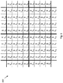
- FIG. 2 describes a square detector array, wherein every square denotes a detection subunit (pixel).
- a square detector array optically fitted with a corresponding filter array may be described such that each detector unit (pixel) is covered by one filter unit that is denoted by ⁇ i, where 'i' is an index that goes from one to N. N denotes the number of different wavelength bands that are defined in the array.
- ⁇ i may be the central wavelength of the spectral response that results from the combination (product) of the spectral response of the detector and the spectral response of the attached filter.
- the arrangement of the filters may be periodic and may be divided into unit cells.
- the size of a unit cell may be (1x ⁇ N) 2, where 1 is the length of each quadratic pixel of the detectors array.
- the resolving limit of the human eye are 10 microns (393.7 microinches) on the retina.
- the requirement from the spatial resolution of the spectral imaging system may accordingly determine so that every ⁇ N pixels would image 10 microns (393.7 microinches) of the retina.
- the retinal camera is a non-mydriatic fundus camera of a 45 degrees FOV and the image on the long axis covers an arc of retina of approximately 8.64 mm, it may be required that detector array 150 in FIG. 1 comprise at least 864x ⁇ N pixels on the long axis.
- ⁇ N that would satisfy the aforementioned requirement will be five, implying 25 spectral points for every 10x10 square microns on the retina.
- Typical digital cameras of 5 million pixels would already satisfy this requirement.
- this requirement is satisfied even on the short axis of Kowa's NONMYD 7 and Topcon's TRC-NW8 when applying NIKON's D80 camera back with 10 million pixels of 3872 pixels on the long axis and 2592 pixels on the short axis.
- a specific application of retinal spectral imaging may be the estimate of oxygen saturation levels over the entire imaged retina, including vessels and retinal tissue.
- FWHM full-width-half-maximum
- These wavelengths are only representative of one embodiment. Other wavelengths may provide usable results and are incorporated herein. In one example, shifting each wavelength up to 20nm may provide usable results.
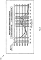
- FIG. 3 depicts the central spectral position of these wavelength bands relative to the absorption spectra of oxygenated and de-oxygenated hemoglobin. Small corrections to these values may be required when adapting to the specific spectral response of a chosen detectors array.
- every unit cell, or every pixel in the case where an interpolation technique is used may be analyzed in order to provide physiological or chemical information related to the imaged object at the location that is imaged by the respective unit cell, or pixel,
- the methods and systems described herein may be used to obtain a spectrum that may be used to estimate oxygen saturation using various techniques.
- a spectrum obtained by the methods and systems herein may work well with the estimation technique suggested by Shonat et al. in Biophysical Journal 73, page 1223 (1997 ).
- Various analysis techniques of a spectrum that may be obtained by the methods and systems described herein has been discussed in numerous papers (see for example Schweitzer et al. in SPIE 2393, page 210 (1995 ), Beach et al. in SPIE (1998 ) and US patent 6,276,798 ). Therefore, the methods and systems described herein provide immediate benefit to currently used analysis techniques.
- grey levels Black and White image detector 150 ( FIG. 1 ) may be used.
- desired spectral bands may be obtained by fitting a filter array to detector arrays of commercially-available color digital cameras, e.g., RGB (red, green, and blue)-coated and CYMG (cyan, yellow, magenta, green)-coated arrays.
- FIG. 4 depicts the spectrum of each one of these colors, in accordance with an embodiment of the present invention.
- the filters in the corresponding arrays may be then designed in a way that their combination (product of spectra) with the existing CFA pattern yields the desired spectral bands.
- FIG. 5 shows wavelength bands when the imaging detector array is already covered with a quadratic BAYER RGB pattern, in accordance with another embodiment of the present invention.
- the BAYER RGB pattern unit cell consists of four pixels, two of which are green-coated (G), one is red-coated (R), and the last one is blue-coated (B) as denoted by the R, G, and B letters in FIG. 5 .
- the filter array may be optically fitted on the RGB detector array and may have 4x4-unit cell as illustrated by the thick solid lines in FIG. 5 .
- FIG. 6 depicts wavelength bands for the case in which the imaging detector array is already covered with a quadratic CYMG pattern, in accordance with an embodiment of the present invention.
- the CYMG pattern unit cell consists of four pixels, one for each color as denoted by the letter C, Y, M, and G, in FIG. 6 .
- the filter array may be optically fitted on the CYMG detector array and may have accordingly a 4x4 unit cell as illustrated by the thick solid lines in FIG. 6 .
- Figs. 5 and 6 it may be in principle possible to apply 16 wavelength bands. This may become necessary, depending on the application of the spectral imaging system. Additionally, it may be noted that in Figs. 5 and 6 , all nine wavelength bands may be found in "rolling" 3x3 unit cells supporting spectral interpolation algorithms that may increase the effective spatial resolution of a resulting spectral image.
- the isosbestic points of oxygenated and de-oxygenated hemoglobin spectra are at 522, 549, 569, and 586 nm.
- the extinction coefficients of both oxygenated and non-oxygenated hemoglobin may be equal.
- the oxygenated hemoglobin (HbO2) maxima are at 542 and 577 nm; and the non-oxygenated hemoglobin (Hbr) maximum is at 555 nm. Therefore, the aforementioned choice of spectral bands may be optimal for reconstructing the hemoglobin spectrum.
- Interference filters with these characteristics may be found off-shelf, and various companies offer the capability of creating such dielectric dichroic (interference) filter arrays on thin films in the dimensions that match the sizes and shapes that are depicted in the embodiments of this invention.
- an interference filter array a micro lens array may be added in order to control the angular content of the beam reaching each one of the filters in the array because the performance of interference filters depends on the angle of the incident light. This angle may also be controlled by an array of micro-pinholes that would be attached to the filter array so that a micro-pinhole is centered in front of every filter in the array.
- One process combines modern optical thin film deposition techniques with microlithographic procedures. This process enables micron-scale precision patterning of optical thin film dichroic coatings on a single substrate.
- a dichroic filter may selectively transmit light according to its wavelength.
- Ocean Optics can create multi-patterned arrays of different optical filters.
- the process may also be applied to CCD camera detectors. Since, this process relies on precision microlithography instead of cut metal masks to pattern the deposited coatings, features (coated areas) as small as 2 ⁇ m can be produced, with spatial registration to within 1 ⁇ m. The cost of microlithographic tooling does not increase significantly with pattern complexity.
- a resist lift-off technique for applying patterned multispectral coatings on a single substrate or, for some cases, directly on the surface of a CCD.
- This technique has been applied successfully at DSI since the early nineties.
- the coatings can have micron-scale features, consist of as many as 100 coating layers, and meet stringent environmental and durability standards.
- Production of multispectral filters using resist lift-off starts with a bare, clean substrate.
- the substrate is then treated with an adhesion promoter, which helps the photoresist adhere to the substrate. After the adhesion promoter, positive photoresist is applied.
- the next step, following proper application of the photoresist, is exposure. Once the desired area has been exposed, the resist from the exposed area is removed.
- the substrates with the patterned photoresist masks are then placed in a vacuum coating chamber where controlled deposition of the desired coating is accomplished. After deposition, the coated substrate is submerged in solvent, which dissolves the photoresist, allowing the coating on top of the photoresist to be washed away and leaving the desired patterned coating. This procedure is repeated to construct multiple filters on the same substrate.
- a non- mydriatic digital retinal camera (that acquires snapshot color images of the retina through a minimally and spontaneously dilated pupil) may be turned into a snapshot spectral imaging system by fitting a filters array to its sensors array.
- the suggested spectral bands together with an appropriate de-mosaicking technique and software analysis may yield estimation of oxygen saturation levels across the imaged retina.
- Oxygen saturation maps can serve for diagnosis of retinal vascular diseases and for automatic classifications of these diseases in general. Consequently, the efficiency of eye screening programs may be improved.
- CFA-based color digital cameras have been incorporated either internally into eye imaging systems or as an add-on and exchangeable component.
- the latter approach has not been abandoned although all new instruments are designed digital from the start because the speed in which new sensor arrays and camera backs are appearing in the market, offering constant improvement in spatial and spectral resolutions, sensitivity, speed of acquisition, color accuracy, etc.
- the present invention can follow up on these commercial trends and fit appropriate filter arrays to newly appearing camera backs, enhancing the applicability of corresponding imaging systems.
- the invented system deals with all the problems that have prevented the commercialization of a retinal oximeter until this day, i.e., eye movements, the number of spectral bands that compose the reconstructed spectrum, image resolution, manufacturability, and cost-efficiency.
- a rectangular array of light-sensing elements may be used.
- the present invention is not restricted to this arrangement and can be applied to any tessellation geometry as long as the single pixel size is within the range that allows the narrow band filters adaptation.
- sensors of new shapes other than rectangular and new sampling schemes other than rectangular sampling may be used in order to optimize resolution over a given sensors array total size without reducing the active area of the individual sensor.
- the present invention provides unique advantages over existing or conventional multi-spectral alternatives in terms of image registration, calibration, light transmission, cost, physical size, and mechanical robustness.
- the present invention allows a large number of spectral points in a snapshot to a level that is not possible applying other aforementioned technologies and systems.
- the present invention when applied to non-mydriatic retinal cameras, the present invention paves the way to automatic disease classification upon eyes screening, e.g., in the case of diabetic patients.
Landscapes
- Physics & Mathematics (AREA)
- Spectroscopy & Molecular Physics (AREA)
- Health & Medical Sciences (AREA)
- Life Sciences & Earth Sciences (AREA)
- General Physics & Mathematics (AREA)
- Engineering & Computer Science (AREA)
- Surgery (AREA)
- Public Health (AREA)
- Biomedical Technology (AREA)
- Heart & Thoracic Surgery (AREA)
- Medical Informatics (AREA)
- Molecular Biology (AREA)
- Biophysics (AREA)
- Animal Behavior & Ethology (AREA)
- General Health & Medical Sciences (AREA)
- Ophthalmology & Optometry (AREA)
- Veterinary Medicine (AREA)
- Optics & Photonics (AREA)
- Pathology (AREA)
- Multimedia (AREA)
- Signal Processing (AREA)
- Eye Examination Apparatus (AREA)
- Investigating Or Analysing Materials By Optical Means (AREA)
- Image Input (AREA)
- Measurement Of The Respiration, Hearing Ability, Form, And Blood Characteristics Of Living Organisms (AREA)
Description
- This application claims the benefit of the
U.S. Provisional Application No. 61/064,420 filed on March 5, 2008 - This invention relates to spectral imaging, and more particularly, to a method and system for obtaining spectral images of retina.
- Spectral images are the images in which spectral information beyond the information that is required for producing a typical color image (that is typically based on the red, green, and blue components) is provided for every point of the image or pixel. This spectral information can be related to physiological properties of an object (e.g., physiological properties of the tissue as in retina being imaged) by choosing appropriate wavelength bands. Physiological properties can be related to different pathological conditions and can be further used clinically for diagnosis and for the indication of disease development. Therefore, the spectral images are especially useful because they incorporate physiological information together with anatomical and structural information.
- A specific case in which spectral imaging is applicable is spectral imaging of the retina. Spectral imaging of the retina presents a unique opportunity for direct and quantitative mapping of retinal biochemistry. For example, blood oximetry is enabled by the strong variation of the hemoglobin absorption spectra with oxygenation. This is pertinent both to research and to clinical investigation and diagnosis of retinal diseases such as diabetic retinopathy, glaucoma, and age-related macular degeneration. These diseases are the major causes of blindness in the industrial world, in which their percentage is constantly growing as the result of environmental factors and the growth of life expectancy. In order to deal with these epidemic tendencies several screening programs have been started such as the UK National Screening Program.
- The principle goal of such eye screening programs is the early detection of 'Diabetic Retinopathy,' wherein temporal retinal images of diabetic patients are obtained and sent for evaluation. The state of the retina is visually classified, and a referral is accordingly issued, inviting the patient to a specialist or scheduling the next retinal photography.
- However, the applicability of these screening programs depends on minimizing the costs that are involved. The major contribution to these costs is the employment of professional people, especially medical doctors (MDs). For this reason, the programs are based on involving MDs only when necessary. Hence, the quality of the retinal images and the level of classification become crucial.
- Further, in order to support efficient and cost-effective screening, different types of digital retinal cameras have been developed (e.g., CANON's CR-DGi and CR-1, Kowa's NONMYD7, Nidek's AFC-230/210, and Topcon's NW8.) The digital retinal cameras are designed to support efficient acquisition of retinal photographs by non-professional users and with minimal requirements on pupil dilation. Similarly, computer software has also been developed to support efficient and cost-effective networking and archiving of digital retinal photographs. However, classification of the images is performed manually, which is an intensive work and is subject to errors.
- The optimal exploitation of spectral imaging of the eye presents a set of challenging problems, including the poorly characterized and poorly controlled optical environment of structures within the retina to be imaged; the erratic motion of the eyeball; and the compounding effects of the optical sensitivity of the retina and the low numerical aperture of the eye. Various systems have disclosed the basic science of spectral imaging (e.g., monitoring oxygen saturation levels by spectral imaging of the eye.) However, the conventional systems provide comparatively less sensitivity and specificity due to the time required to obtain enough spectral points to support reliable calculations. In addition, in order to eliminate the effect of eye movement, the typical speed for completing the measurement must be under 0.1 second, while the conventional systems typically require up to several seconds.
- The first retinal imaging oximeter based upon photographic techniques was proposed by Hickam et al. in Circulation 27, page 375 (1963). This system disclosed a modified fundus camera that images the retina at two different wavelengths, filters the image from incandescent light sources, and extracts retinal blood vessels optical density with Beer-Lambert law. Measurements with this system have lead to inaccurate results because of the Beer-Lambert Law, which strictly limits two-wavelength oximetry only to hemolyzed solutions.
- Pittman and Dulling in Applied Physiology 38, page 315 (1975), showed that more accurate results of retinal oximetry can be achieved using three wavelengths instead of two. This model took into account the scattering coefficient wavelength dependence.
- Three-wavelength oximetry is based on several important principles. The first of these states that light absorption by blood depends on oxygen saturation (OS) and wavelength. Second, a relationship exists between a measurable optical quantity like optical densities and the extinction coefficient of the mixture of oxygenated hemoglobin (HbO2) and deoxygenated hemoglobin (Hb) at a given OS as explained by van Assendelft in Spectrophotometry of hemoglobin derivatives (Springfield, IL: Thomas 1970), page 321. Finally, optical densities at two specific wavelengths can be compared to the optical density at a third specific wavelength; hemoglobin absorption values may then be calculated and be used to accurately obtain percent OS (Pittman and Duling in Applied Physiology 38, page 315 (1975)). The advantages and disadvantages of three wavelengths using existing technology have been explored by van Norren and Tiemeijer in Vision Res. 26, page 313 (1986) and by Delori and Pflibsen in Applied Optics 27, page 1113 (1988).
- Three wavelength oximetry has been adapted for real-time measurements of retinal vessel OS as described by van Assendelft in Spectrophotometry of hemoglobin derivatives (Springfield, IL: Thomas 1970), page 321, and by Delori and Pflibsen in Applied Optics 27, page 1113 (1988). These retinal oximeters use a bright source of non-collimated light (such as a broad-spectrum halogen or arc lamps) that is filtered to provide three selected wavelengths. The light source and the filters are cooperatively selected to provide at least one isobestic wavelength (i.e., a wavelength at which hemoglobin absorption is essentially independent of OS) and at least one wavelength for which blood absorption is dependent upon OS. To probe a selected area of the retina, the light is focused on either a large caliber retinal artery or a large caliber retinal vein. The percent OS is calculated from measurements of the light reflected from either the artery (in which hemoglobin oxygenation is relatively high) or the vein (in which hemoglobin oxygenation is relatively low), and from the retinal pigment epithelium (RPE) background. However, this technique for performing retinal oximetry is complicated to control, requires precise focusing on retinal blood vessels and a complicated filtering system to produce a multi-wavelength probe. Thereby, it limits percent OS measurements to large caliber blood vessels and does not allow OS measurements to be made in the intra-retinal capillary beds.
- In contrast to the above, "Full spectrum" methods (spectral methods that employ a large number of wavelengths values) have been used to record the reflectance profile versus wavelength from the ocular fundus. "Full spectrum" techniques use a high resolution imaging spectrograph to collect the spectral information from a band of tissue in a single spatial dimension. These spectrographs typically apply diffraction gratings and prisms in the spectral measurement of tunable wavelength. "Full spectrum" methods support the addition of parameters to the models that describe the spectral properties of the living (retinal) tissue, giving rise to more accurate estimates of OS in tissues outside large caliber blood vessels. Outside the large caliber vessels, the spectral signature of hemoglobin is less dominant than in the blood vessels. Examples can be found in F. C. Delori, "Reflectometry measurements of the optic disc blood volume," in Ocular Blood Flow in Glaucoma Means, Methods and Measurements, G. N. Lambrou, E. L. Greve eds., Berkely, Calif., Kugler and Ghedini, pp. 155-163 (1989); and F. C. Delori et al., "Spectral reflectance of the human ocular fundus," Appl. Optics, Vol. 28, pp. 1061-1077 (1989). In 1995, Schweitzer et al. [D. Schweitzer, M. Hammer, J. Kraft, E. Thamm, E. Koenigsdoerffer, and J. Strobel, "Calibration-free measurement of the oxygen saturation in retinal vessel of men," Proc. SPIE 2393, 210-218 (1995).] built an instrument that could image the retina spectroscopically with selecting light source wavelengths from 400 nm (15.75 micro inches) to 700 nm (27.56 micro inches) in 2 nm (0.07874 micro inch) intervals; an empirical scattering model was used in their calculations.
-
Gil et al. disclose in US Patent 6276798 a method and apparatus for spectral bio-imaging of the retina applying Fourier Transform to recover continuous spectra from interferograms that are obtained for each pixel by a Sagnac type interferometer. The interferometer is mounted on the video output of a fundus camera. Yoneya et al. have used such a system in various clinical studies, one of which is described in Ophthalmology 109(8), page 1521 (2002). The studies have shown that the clinical applicability of the technique is limited by the long acquisition time. Subsequently, the measured data contains noise and may not be accurate due to the movements of the eye during the acquisition. -
Hirohara et al. in U.S. Patent Application No. 2007/0002276 andMihashi et al. in U.S. Patent Application Nos. 2008/0007691 and2008/0007692 disclose a spectroscopic fundus measuring apparatus that applies a liquid crystal tunable filter in combination with a spectral characteristic correction filter in order to select the transmission wavelength in the digital imaging system that is attached to a fundus camera. The filters are disposed either in the illumination optical system or in the light receiving system, and a special method is applied in order to shorten the wavelength shifting time upon the acquisition of the spectral image. The resulting acquisition time is still in the range of seconds. A method is provided to eliminate image position changes due to eye movements and a computer program is provided to align spectral images positions almost fully automatically. - Alabboud et al. in the Proceedings of SPIE, Volume 6631, and page 66310L (2007), describe a system comprising a liquid crystal tunable filter that is integrated into the illumination system of a conventional fundus camera to enable time-sequential, random access recording of narrow-band spectral images, Image processing techniques are used to eradicate the artifacts that may be introduced by time-sequential imaging.
- Kagemann et al. in Society of Photo-Optical Instrumentation Engineer (2007) have used Fourier domain Optical Coherence Tomography (OCT) data to assess retinal blood oxygen saturation in three-dimensional disk-centered retinal tissue volumes. After removing DC and low-frequency a-scan components, an OCT fundus image is created by integrating total reflectance into a single reflectance value. Thirty fringe patterns are sampled, 10 each from the edge of an artery, adjacent tissue, and the edge of a vein, respectively. A-scans are recalculated, zeroing the DC term in the power spectrum, and used for analysis. Optical density ratios (ODRs) are calculated as ODRArt=ln(Tissue855/Art855)/ln(Tissue805/Art805) and ODRVein=ln(Tissue855/Vein855)/ln(Tissue805/Vein805) with Tissue, Art, and Vein representing total a-scan reflectance at the 805- or 855-nm (33.66 microinches) centered bandwidth. A difference between arterial and venous blood saturation was shown to be detected by this technique, suggesting that retinal oximetry may possibly be added as a metabolic measurement in structural imaging devices. However, this technology is yet to be developed completely.
- In summary, all "Full spectrum" systems require an acquisition time during which the eye moves relative to the optical measuring system, giving rise to spectral distortion and patient discomfort. It is shown herein that these problems are resolved by the application of snapshot spectral imaging techniques, which remove the fundamental difficulties that are associated with time-sequential techniques.
- Snapshot spectral imaging systems minimize or completely waive the problem with eye movements that distort the actual spectrum of the imaged object and aim at obtaining enough spectral information in a single exposure of the imaging detectors.
- Hardarson et al. in Investigative Ophthalmology & Visual Science 47/11, page 5011 (2006), have used the MultiSpec Patho-Imager (Optical Insights, Tucson, AZ) on the video output of a fundus camera in order to obtain four images in four different wavelength bands on a single CCD detector array in one snapshot. Their studies show relative success in estimating OS in large retinal vessels but not in the surrounding retinal tissue. They conclude that improvement can be achieved with the incorporation of correction for additional tissue optical properties, which would require image data in more wavelength bands.
- Ramella-Roman et al. in Optical Society of America 16/9, page 6170 (2008), describe a multi aperture system capable of capturing six identical images of the human fundus at six different spectral bands. The system is based on lenslet array architecture. The multi-aperture system is mounted on the image output of a fundus camera to acquire spectroscopic sensitive images of the retina vessel and ultimately to calculate OS in the retina in vivo. In vivo testing on healthy volunteers was conducted and yielded results of OS similar to the one reported in the literature, with arterial OS ∼0.95 and venous OS ∼ 0.5. The system suffers from several drawbacks. Among those is the need of registration among the six images that fall on the single image detector of the system. This need results from the specific properties of optical set up of the system. Additionally, a focusing screen that is used in the system in order to reduce the depth of field of the incorporated lenslets reduces the light intensity that eventually reaches the image detector, thus reducing the signal-to-noise ratio of the image. Finally, observing the spectral analysis of the results presented by Ramella-Roman et al. actually shows that the number of wavelength bands for every pixel in the image is still limiting fitting of OS model with measured data.
- Johnson et al. in Journal of Biomedical Optics 12(1), 014036 (January/February 2007) describe the use of computed tomographic imaging spectrometer (CTIS) to perform snapshot hyper-spectral imaging of the eye. CTIS captures both spatial and spectral information in a single frame. Its acquisition time is constrained by the exposure time of the fundus camera on which the CTIS is mounted (typically about milliseconds) and a required signal-to-noise-ratio. It is capable of acquiring a complete spatial-spectral image cube in about 3 ms from 450 to 700 nm (17.72 to 27.56 microinches) with 50 bands, eliminating motion artifacts and pixel misregistration. There are no narrow-band filters, and nearly all collected light (about 70%) is passed to the detector at all times. The CTIS is based on diffractive grating collimated in space and which disperses the image in two dimensions. A second lens re-images the pattern onto the image detector. This produces multiple, spectrally-dispersed, images of the retina that are recorded by a focal plane array (FPA). From the captured intensity pattern, computed-tomography algorithms are used to reconstruct the scene into a "cube" of spatial (x and y) and spectral (wavelength) information. Thus, each image is not simply composed of single wavelengths; spatial and spectral information from each object pixel is multiplexed over the entire detector array. Hence, a single acquisition contains all the information required to reconstruct the spectral image cube.
- Initial results of studies on human healthy subjects show a clear distinction between veins, arteries, and background. Regions within vessel capillaries agree well with the 30 to 35% oxygen saturation difference expected for healthy veins and arteries. The saturation for most of the background spatial locations in between the capillary regions shows a tendency to be within the 90 to 100% regime. This is consistent with the subjects being healthy. As the CTIS records a multiple of spectrally-dispersed images on a single FPA, which is the detector array of a fundus camera, the genuine field of view (FOV) of the host fundus camera is reduced, typically by a factor of almost three. Accordingly, the maximal FOV of the CTIS is 18 degrees, corresponding to a 50 degrees fundus camera. Additionally, complicated calibration and extensive numerical approximations are required for recovering the spectral image, each contributing its error and SNR reduction as well as long processing time. CTIS is limited by inefficient usage of both the detector array and its large number of spectral bands when only a few are required.
- Alabboud et al. in the proceedings of the SPIE, Volume 6631, and page 66310L (2007), describe a snapshot spectral imaging system and technique dubbed IRIS that employs polarizing interferometery and Wollaston prism beam splitters to simultaneously replicate and spectrally filter images of the retina into multiple spectral bands onto a single detector array. The system records eight images at eight different wavelength bands on a single photo-detector.
- Results of early clinical trials acquired with IRIS together with a physical model, which enables oximetry map, were reported. However, the system as described yields a small field of view and gives rise to image intensity loss upon splitting the single-band images to their appropriate locations on the image detector. Additionally, it is based on a non-compact set that does not fit existing retinal imaging systems.
- Kong et al. have used a method to develop a multispectral camera to acquire spectral images in a snapshot as described in Proc. SPIE 6915, 69153K (2008). They have used a multi-wavelength narrowband filter to replace the standard Bayer color filter on monochrome CMOS sensor of a digital camera, creating in this way a miniaturized multispectral imager. The device contains a mosaic filter for four wavelengths: 540, 577, 650, and 970 nm (38.19 microinches), with the purpose of detection of erythema and bruises in persons with darkly pigmented skin. In general term, this system is disclosed in the International Patent Application
PCT/US2007/087479 . Jessica C. Ramella-Roman et al., proceedings of SPIE, vol. 6426, 1 January 2007, pgs. 64261J-64261J-5, XP055039451 discloses a lenslet-based device for measuring oxygen saturation in the retina. - In light of the above discussion, there is a need for a method and system that provides automatic classification of diabetic retinopathy. In addition, there is a need for a method and system that may significantly affect the efficiency and cost- effectiveness of screening techniques. Further, there is a need for a method and system that enables obtaining spectral images of the retina by the aforementioned non-mydriatic retinal cameras after fitting them with already modified camera-backs. Still further, such a method and system may utilize algorithms that apply the spectral information to estimate blood hemoglobin oxygen saturation in each point of the images for automatic classification of the progress of retinal vascular diseases such as diabetic retinopathy.
- Accordingly, it is an object of the invention to provide an improved method and system for spectral imaging of the eye that provides spectral points (wavelength bands) to deal with the poorly characterized and poorly controlled optical environment of structures within the retina under the compounding effects of the optical sensitivity of the retina and the low numerical aperture of the eye; without registration and spectral distortion problems that are associated with time-sequential techniques because of the erratic motion of the eye ball; and without the complexity, small field of view, and intensity loss that characterize current snapshot techniques.
- The present invention discloses a method and system for spectral imaging of the eye. In accordance with an embodiment of the present invention, a filter array fitted to the detector array of a digital imaging system is disclosed. Currently, a color filter array (CFA) is used in the image sensor to separate different color photons in incident light. An example may be of a color filter array having a Bayer filter pattern that is placed in front of the pixel array to obtain the color information of the optical image. In a Bayer filter pattern CFA, the color filters are quartet-ordered with successive rows that alternate red and green filters, then green and blue filters. Each of the color filters is sensitive to one color and allows photons of that color to pass through and reach the corresponding photo-sensor. The photo-sensor in each pixel thereby detects and measures only the light of the color associated with the filter provided within that pixel. There are various other color filter arrays formed with alternative filter patterns, such as a CYMG (cyan, yellow, magenta, green) filter pattern, a CKMY (cyan, black, magenta, yellow) filter pattern, an RGBE (red, green blue, emerald) filter pattern, and other patterns having red, green, and blue filters and another color filter arranged between green and blue filters, and others.
- The CFA technology has been widely used in the digital camera industry since it provides several advantages like low cost, exact registration, and strong robustness. The idea of CFA has also been extended to multi-spectral filter array (MSFA). In MSFA more than three color bands are used (e.g. visible and infrared). Moreover, when dealing with retinal imaging, the resolution of SLR camera backs is much higher than the intrinsic resolution of the human eye optics; accordingly, it is shown in the description of this invention below that it is possible to increase (more than triple) the number of spectral bands without reducing the effective resolution of the system.
- According to one aspect of the present invention, there is provided a system of eye spectral imaging as defined in claim 1 hereinafter.
- According to another aspect of the present invention, there is provided a method for obtaining spectral images of an eye as defined in claim 12 hereinafter.
- These and other systems, methods, objects, features, and advantages of the present invention will be apparent to those skilled in the art from the following detailed description of the preferred embodiment and the drawings.
- The invention and the following detailed description of certain embodiments thereof may be understood by reference to the following figures:
-
FIG. 1 depicts a schematic view of a fundus camera with an exchangeable digital camera back; -
FIG. 2 depicts a graphic illustration of the arrangement of spectral band filters in the filter array of the principle embodiment of the invention; -
FIG. 3 depicts the position of chosen central wavelength values on top of hemoglobin absorption spectra; -
FIG. 4 depicts the spectra of RGB and CYMG-coated detector arrays; -
FIG. 5 depicts an arrangement of spectral bands on top of an RGB-coated quadratic imaging detector array in order to realize an embodiment of the invention; and -
FIG. 6 depicts an arrangement of spectral bands on top of a CYMG-coated quadratic imaging detector array in order to realize an embodiment of the invention. - Throughout this disclosure, the phrase "such as" means "such as and without limitation". Throughout this disclosure, the phrase "for example" means "for example and without limitation". Throughout this disclosure, the phrase "in an example" means "in an example and without limitation". Throughout this disclosure, the phrase "in another example" means "in another example and without limitation". Generally, examples have been provided for the purpose of illustration and not limitation.
-
FIG. 1 depicts the principle elements of a typicaleye fundus camera 100 with a digital camera back 148, in accordance with an embodiment of the present invention. Thecamera 100 is described here in general only in order to better clarify the embodiments of this invention. A chinrest face holder 108 is an extension ofcamera base 102 and may include aneye fixation lamp 110. A joystick-adjustable stage 114 may be placed on top of thecamera base 102 that holds the optical system orunit 112. By use ofjoystick 114,stage 104 may be moved back and forth, right and left, andoptical unit 112 may be moved up and down in order to bring theoptical unit 112 into correct optical contact with the eye element that is imaged. The optics of thefundus camera 100 can be divided into illumination optics and imaging optics. The illumination optics may consist of aflash lamp 120, such as xenon lamp,continuous illumination source 122, such as halogen lamp,exchangeable filter 124,pupil 128,folding mirror 130, perforatedmirror 132, andobjective lens 134. The imaging optics may comprise an objective lens,beam splitter 140, digital camera back 148, with digital detector array 150 (CCD or CMOS that is illustrated in the round blowup), flippingmirror 142, andeyepiece 144.Digital camera 100 may be connected tocomputer 152 withdisplay 154, into which the digital image is downloaded. - The process of acquiring an image of an eye part, e.g., the retina, may start with dilating the eye pupil of the patient with mydriatic drops in order to keep the pupil dilated all through the photography process, allowing enough light in and out of the eye. The patient may then rest the head on the chin
rest face holder 108 so that the eye is relatively fixed in space. This may follow with an alignment process in which the eye is illuminated by illumination beam 118, originating from the continuouslight source 122.Reflection light beam 138 may be directed toeyepiece 144, with flippingmirror 142 in the appropriate position, allowing the operator to see the image of the retina and aligningoptical unit 112 by aid ofjoystick 114 until an optimal image is obtained. At this point an image may be recorded by pressing the electric trigger onjoystick 114, activatingflash lamp 120 and thedigital image detector 150. In a non-mydriaticfundus camera eyepiece 144 may be replaced by a digital alignment system with a monitor display that provides graphical alignment aids and may typically operate under near-infrared (NIR) illumination that is obtained with an appropriatelight source 122 andfilter 124. Under NIR illumination, the eye pupil may remain dilated, allowing enough light in and out of the eye, contracting in delay to the aforementioned flash, thus allowing image acquisition without mydriatic dilation drops. The maximal Field of View (FOV) of typical non-mydriatic cameras is 45 degrees, such that in its long axis the retinal image covers approximately 8.64 mm (approximately 0.3402 inch). - In accordance with an embodiment of the present invention, a multi-spectral filters array may be optically fitted or directly deposited onto an
imaging detector array 150 of adigital fundus camera 100, thus producing snapshot spectral images of the retina. This has been illustrated inFIG. 2 that describes a square detector array, wherein every square denotes a detection subunit (pixel). - Referring to
FIG. 2 , a square detector array optically fitted with a corresponding filter array may be described such that each detector unit (pixel) is covered by one filter unit that is denoted by λi, where 'i' is an index that goes from one to N. N denotes the number of different wavelength bands that are defined in the array. In accordance with a preferred embodiment, λi may be the central wavelength of the spectral response that results from the combination (product) of the spectral response of the detector and the spectral response of the attached filter. - The arrangement of the filters may be periodic and may be divided into unit cells. Each unit cell may consist of exactly N different filters and the position of each λi filter within the cell may be indicated by the (m,n), where m=1... √N and n=1... √N, respectively. The size of a unit cell may be (1x√N) 2, where 1 is the length of each quadratic pixel of the detectors array. A meaningful spectral image may be constructed when the optical set up is such that a unit cell images a portion of the object that is spectrally homogeneous from the applicative point of view. Hence, when acquiring an image through the filters array of
FIG. 2 , a spectrum consisting of N=9 central wavelength points may be reconstructed. When dealing with imaging the retina, it is generally accepted that the resolving limit of the human eye are 10 microns (393.7 microinches) on the retina. The requirement from the spatial resolution of the spectral imaging system may accordingly determine so that every √N pixels would image 10 microns (393.7 microinches) of the retina. In a preferred case wherein the retinal camera is a non-mydriatic fundus camera of a 45 degrees FOV and the image on the long axis covers an arc of retina of approximately 8.64 mm, it may be required thatdetector array 150 inFIG. 1 comprise at least 864x√N pixels on the long axis. - For example, Canon's CR-DGi 45 degrees non-mydriatic fundus camera fitted with an EOS-1DS Mark II SLR camera back of 16.7 million pixels and 4992 pixels on the long axis. √N that would satisfy the aforementioned requirement will be five, implying 25 spectral points for every 10x10 square microns on the retina.
- Certain unpublished experiments have shown that the minimal value of N that is required for correctly recovering the spectrum of oxygenated and non-oxygenated hemoglobin in arterial and venous human blood is nine. Therefore, N=9 would mean that sensor arrays with at least 864x√N=2592 pixels on the long axis would yield a spectral image with a spatial resolution matching the resolution of the human eye. Typical digital cameras of 5 million pixels would already satisfy this requirement. Moreover, this requirement is satisfied even on the short axis of Kowa's NONMYD 7 and Topcon's TRC-NW8 when applying NIKON's D80 camera back with 10 million pixels of 3872 pixels on the long axis and 2592 pixels on the short axis. The aforementioned CANON's CR-DGi 45 degrees non-mydriatic fundus camera with the EOS-1DS Mark II SLR camera back will be resolving 5.19 microns (204.3 microinches) on the retina with N=9, which is beyond the resolution of a typical human eye optics.
- A specific application of retinal spectral imaging may be the estimate of oxygen saturation levels over the entire imaged retina, including vessels and retinal tissue. With N=9 a representative spectra that would distinguish clearly between oxygenated and non-oxygenated hemoglobin can be reconstructed from spectral bands of full-width-half-maximum (FWHM) of 15 nm (0.5906 micro inch) that are centered at λ1,...,9=522, 532, 542, 549, 555, 569, 577, 586, 600 nm, respectively. These wavelengths are only representative of one embodiment. Other wavelengths may provide usable results and are incorporated herein. In one example, shifting each wavelength up to 20nm may provide usable results.
-
FIG. 3 depicts the central spectral position of these wavelength bands relative to the absorption spectra of oxygenated and de-oxygenated hemoglobin. Small corrections to these values may be required when adapting to the specific spectral response of a chosen detectors array. - In the periodic arrangement of
FIG. 2 , denoting the position of λi by (mi,ni) it may be observed that the spectral bands positioned at (mi,ni) are equal for all the unit cells. For example λ7 is always positioned (3,1). Accordingly, the reconstruction of the spectrum attributed for each unit cell from the intensities recorded on each pixel of the arrays of the detectors may be easily done in a straightforward manner. Alternatively, more sophisticated methods and algorithms can be applied in reconstructing the spectral image, among which are methods in which each pixel is attributed the full spectrum by interpolation on the intensity values recorded at nearest-neighbor pixels of equal spectral band. In general, different de-mosaicking techniques as described herein and elsewhere may be used to optimize the retrieving of the spectral image from the readings of the detectors array, some useful de-mosaicking techniques are known to those skilled in the art. - Once a spectrum is attributed, every unit cell, or every pixel in the case where an interpolation technique is used, may be analyzed in order to provide physiological or chemical information related to the imaged object at the location that is imaged by the respective unit cell, or pixel,
- In accordance with an embodiment of the present invention, the methods and systems described herein may be used to obtain a spectrum that may be used to estimate oxygen saturation using various techniques. A spectrum obtained by the methods and systems herein may work well with the estimation technique suggested by Shonat et al. in Biophysical Journal 73, page 1223 (1997). Various analysis techniques of a spectrum that may be obtained by the methods and systems described herein has been discussed in numerous papers (see for example Schweitzer et al. in SPIE 2393, page 210 (1995), Beach et al. in SPIE (1998) and
US patent 6,276,798 ). Therefore, the methods and systems described herein provide immediate benefit to currently used analysis techniques. - In an aspect of the present invention, grey levels (Black and White) image detector 150 (
FIG. 1 ) may be used. In alternative embodiment of the present invention desired spectral bands may be obtained by fitting a filter array to detector arrays of commercially-available color digital cameras, e.g., RGB (red, green, and blue)-coated and CYMG (cyan, yellow, magenta, green)-coated arrays. -
FIG. 4 depicts the spectrum of each one of these colors, in accordance with an embodiment of the present invention. The filters in the corresponding arrays may be then designed in a way that their combination (product of spectra) with the existing CFA pattern yields the desired spectral bands. -
FIG. 5 shows wavelength bands when the imaging detector array is already covered with a quadratic BAYER RGB pattern, in accordance with another embodiment of the present invention. The BAYER RGB pattern unit cell consists of four pixels, two of which are green-coated (G), one is red-coated (R), and the last one is blue-coated (B) as denoted by the R, G, and B letters inFIG. 5 . The filter array may be optically fitted on the RGB detector array and may have 4x4-unit cell as illustrated by the thick solid lines inFIG. 5 . Each filter may comprise nine wavelength bands, denoted by λ11,12,2,3,5,7,8,9,10...,9=430, 449, 532, 542, 555, 577, 586, 600, 650 nm, respectively, and described accordingly inFIG. 3 . - According to the aforementioned calculation, the number of pixels that may be required in this case in order to comply with the maximal spatial resolution (determined by the resolution of the typical eye optic) would be at least (864x√N=)3456 pixels on the long axis, for N=16. It may be observed that this requirement is fulfilled by the aforementioned SLR camera backs.
-
FIG. 6 depicts wavelength bands for the case in which the imaging detector array is already covered with a quadratic CYMG pattern, in accordance with an embodiment of the present invention. The CYMG pattern unit cell consists of four pixels, one for each color as denoted by the letter C, Y, M, and G, inFIG. 6 . The filter array may be optically fitted on the CYMG detector array and may have accordingly a 4x4 unit cell as illustrated by the thick solid lines inFIG. 6 . Each filter comprises 9 wavelength bands, denoted by λ1,..., 9=522, 532, 542, 549, 555, 569, 577, 586, 600 nm and described accordingly inFIG. 3 . - According to the aforementioned calculation, the number of pixels that would be required in this case in order to comply with the maximal spatial resolution that is determined by the resolution of the typical eye optic would be at least (864x√N=)3456 pixels on the long axis, for N=16.
- It may be noted that in the embodiments of
Figs. 5 and6 , it may be in principle possible to apply 16 wavelength bands. This may become necessary, depending on the application of the spectral imaging system. Additionally, it may be noted that inFigs. 5 and6 , all nine wavelength bands may be found in "rolling" 3x3 unit cells supporting spectral interpolation algorithms that may increase the effective spatial resolution of a resulting spectral image. - Referring to
FIG. 3 , the isosbestic points of oxygenated and de-oxygenated hemoglobin spectra are at 522, 549, 569, and 586 nm. At the isosbestic wavelengths the extinction coefficients of both oxygenated and non-oxygenated hemoglobin may be equal. The oxygenated hemoglobin (HbO2) maxima are at 542 and 577 nm; and the non-oxygenated hemoglobin (Hbr) maximum is at 555 nm. Therefore, the aforementioned choice of spectral bands may be optimal for reconstructing the hemoglobin spectrum. Interference filters with these characteristics may be found off-shelf, and various companies offer the capability of creating such dielectric dichroic (interference) filter arrays on thin films in the dimensions that match the sizes and shapes that are depicted in the embodiments of this invention. In the case of an interference filter array a micro lens array may be added in order to control the angular content of the beam reaching each one of the filters in the array because the performance of interference filters depends on the angle of the incident light. This angle may also be controlled by an array of micro-pinholes that would be attached to the filter array so that a micro-pinhole is centered in front of every filter in the array. - One process combines modern optical thin film deposition techniques with microlithographic procedures. This process enables micron-scale precision patterning of optical thin film dichroic coatings on a single substrate. A dichroic filter may selectively transmit light according to its wavelength. With its process, Ocean Optics can create multi-patterned arrays of different optical filters. The process may also be applied to CCD camera detectors. Since, this process relies on precision microlithography instead of cut metal masks to pattern the deposited coatings, features (coated areas) as small as 2 µm can be produced, with spatial registration to within 1 µm. The cost of microlithographic tooling does not increase significantly with pattern complexity.
- Similarly, another process discloses a resist lift-off technique for applying patterned multispectral coatings on a single substrate or, for some cases, directly on the surface of a CCD. This technique has been applied successfully at DSI since the early nineties. The coatings can have micron-scale features, consist of as many as 100 coating layers, and meet stringent environmental and durability standards. Production of multispectral filters using resist lift-off starts with a bare, clean substrate. The substrate is then treated with an adhesion promoter, which helps the photoresist adhere to the substrate. After the adhesion promoter, positive photoresist is applied. The next step, following proper application of the photoresist, is exposure. Once the desired area has been exposed, the resist from the exposed area is removed. This is accomplished during the development step of the process. The substrates with the patterned photoresist masks are then placed in a vacuum coating chamber where controlled deposition of the desired coating is accomplished. After deposition, the coated substrate is submerged in solvent, which dissolves the photoresist, allowing the coating on top of the photoresist to be washed away and leaving the desired patterned coating. This procedure is repeated to construct multiple filters on the same substrate.
- A non- mydriatic digital retinal camera (that acquires snapshot color images of the retina through a minimally and spontaneously dilated pupil) may be turned into a snapshot spectral imaging system by fitting a filters array to its sensors array. The suggested spectral bands together with an appropriate de-mosaicking technique and software analysis may yield estimation of oxygen saturation levels across the imaged retina. Oxygen saturation maps can serve for diagnosis of retinal vascular diseases and for automatic classifications of these diseases in general. Consequently, the efficiency of eye screening programs may be improved.
- CFA-based color digital cameras have been incorporated either internally into eye imaging systems or as an add-on and exchangeable component. The latter approach has not been abandoned although all new instruments are designed digital from the start because the speed in which new sensor arrays and camera backs are appearing in the market, offering constant improvement in spatial and spectral resolutions, sensitivity, speed of acquisition, color accuracy, etc. The present invention can follow up on these commercial trends and fit appropriate filter arrays to newly appearing camera backs, enhancing the applicability of corresponding imaging systems.
- The invented system deals with all the problems that have prevented the commercialization of a retinal oximeter until this day, i.e., eye movements, the number of spectral bands that compose the reconstructed spectrum, image resolution, manufacturability, and cost-efficiency.
- As illustrated in
Figs. 2 ,5 , and6 , a rectangular array of light-sensing elements may be used. However, the present invention is not restricted to this arrangement and can be applied to any tessellation geometry as long as the single pixel size is within the range that allows the narrow band filters adaptation. Similarly, sensors of new shapes other than rectangular and new sampling schemes other than rectangular sampling may be used in order to optimize resolution over a given sensors array total size without reducing the active area of the individual sensor. - The present invention provides unique advantages over existing or conventional multi-spectral alternatives in terms of image registration, calibration, light transmission, cost, physical size, and mechanical robustness.
- The present invention, allows a large number of spectral points in a snapshot to a level that is not possible applying other aforementioned technologies and systems.
- Moreover, when applied to non-mydriatic retinal cameras, the present invention paves the way to automatic disease classification upon eyes screening, e.g., in the case of diabetic patients.
Claims (12)
- A system of eye spectral imaging comprising: an optical system (112) that images eye tissue onto a digital sensor array (150); and a multi-spectral filter array that is optically fitted with the digital sensor array (150), wherein the multi-spectral filter array is divided into unit cells, each unit cell comprising an integer number of filters with different spectral bands, wherein each detector unit in the digital sensor array is covered by only one filter and the filter array is disposed in close proximity to the digital sensor array (150) in the optical path of the optical system (112) and characterised in that optically fitted comprises:the filter array being deposited on the light sensing surface of the sensor array (150); orthe filter array being deposited on the cover glass attached to a light sensing surface of the sensor array (150); orthe filter array being deposited on the thin film attached to a light sensing surface of the sensor array (150).
- The system of claim 1, wherein the multi-spectral filter array comprises at least nine different spectral bands; AND/OR wherein the spectral bands are designed to support estimation of blood oxygen saturation in a retinal tissue.
- The system of claim 1, wherein the optical system (112) is a fundus camera (100); AND/OR wherein the optical system (112) is a non-mydriatic fundus camera designed to obtain the retinal images without administration of pupil dilation drops.
- The system of claim 1, wherein the multi-spectral filter array comprises a plurality of filter elements each of which is optically associated with an integer number, equal to or larger than one, of detectors of the digital sensor array.
- The system of claim 1, further comprising a micro-lenses array attached to the multi-spectral filter array for limiting an angle of light that is transmitted through the multi-spectral filter array.
- The system of claim 1, wherein each unit cell comprises at least nine filters of nine different spectral bands.
- The system of claim 1, wherein the sensor array (150) lies inside a detachable camera back (148) of the optical system (112).
- The system of claim 1, wherein the sensor array (150) is a grey level sensor array; OR wherein the sensor array (150) is a color-coated sensor array.
- The system of claim 1, wherein the long axis of the image of the eye tissue falls on at least 2592 pixels of the sensor array (150).
- The system of claim 1, further including a computer capable of reconstructing the spectral images; AND/OR further including a program capable of analyzing the spectral images.
- The system of claim 10, wherein reconstructing the spectral images includes de-mosaicking of spectral data from readings of the digital sensor array (150).
- A method for obtaining spectral images of an eye, comprising:taking an optical system (112) that images eye tissue onto a digital sensor array (150);providing a multi-spectral filter array;optically fitting the multi-spectral filter array and the digital sensor array (150), wherein the multi-spectral filter array is divided into unit cells, each unit cell comprising an integer number of filters with different spectral bands, wherein each detector unit in the digital sensor array is covered by only one filter and the filter array disposed between the digital sensor array (150) and an optics portion of the optical system (112) so that light for imaging the eye tissue that reaches the digital sensor array (150) is filtered by the multi-spectral filter array, wherein the sensor array (150) has a light sensing surface and optically fitted comprises:the filter array being deposited on the light sensing surface of the sensor array (150); orthe filter array being deposited on the cover glass attached to a light sensing surface of the sensor array (150); orthe filter array being deposited on the thin film attached to a light sensing surface of the sensor array (150); andfacilitating acquisition of a snap-shot image of the eye tissue with the digital sensor array (150).
Applications Claiming Priority (2)
| Application Number | Priority Date | Filing Date | Title |
|---|---|---|---|
| US6442008P | 2008-03-05 | 2008-03-05 | |
| PCT/IL2009/000249 WO2009109975A2 (en) | 2008-03-05 | 2009-03-05 | Snapshot spectral imaging of the eye |
Publications (3)
| Publication Number | Publication Date |
|---|---|
| EP2252199A2 EP2252199A2 (en) | 2010-11-24 |
| EP2252199A4 EP2252199A4 (en) | 2012-11-07 |
| EP2252199B1 true EP2252199B1 (en) | 2019-05-22 |
Family
ID=41053243
Family Applications (1)
| Application Number | Title | Priority Date | Filing Date |
|---|---|---|---|
| EP09716310.9A Active EP2252199B1 (en) | 2008-03-05 | 2009-03-05 | Snapshot spectral imaging of the eye |
Country Status (5)
| Country | Link |
|---|---|
| US (1) | US8109634B2 (en) |
| EP (1) | EP2252199B1 (en) |
| DE (1) | DE09716310T1 (en) |
| ES (1) | ES2733076T3 (en) |
| WO (1) | WO2009109975A2 (en) |
Cited By (1)
| Publication number | Priority date | Publication date | Assignee | Title |
|---|---|---|---|---|
| DE102019123356A1 (en) * | 2019-08-30 | 2021-03-04 | Schölly Fiberoptic GmbH | Sensor arrangement, method for calculating a color image and a hyperspectral image, method for carrying out a white balance and use of the sensor arrangement in medical imaging |
Families Citing this family (54)
| Publication number | Priority date | Publication date | Assignee | Title |
|---|---|---|---|---|
| DE102007046210A1 (en) * | 2007-09-27 | 2009-04-02 | Carl Zeiss Meditec Ag | Arrangement and method for generating images with extended dynamics |
| DE212012000089U1 (en) * | 2011-08-03 | 2013-12-12 | Ophthametrics Ag | Recording device for receiving a retina of an eye and computer program product |
| EP2788034B1 (en) | 2011-12-09 | 2021-05-26 | Regents of the University of Minnesota | Hyperspectral imaging for early detection of alzheimer's disease |
| CN104411233B (en) | 2012-02-03 | 2017-08-29 | 俄勒冈健康科学大学 | Internal optics flow imaging |
| US9766382B2 (en) | 2012-06-05 | 2017-09-19 | Hypermed Imaging, Inc. | Single-sensor hyperspectral imaging device |
| JP6021462B2 (en) * | 2012-06-21 | 2016-11-09 | オリンパス株式会社 | Imaging module and imaging apparatus |
| US20150018642A1 (en) | 2013-07-12 | 2015-01-15 | Sandeep Gulati | Tissue pathlength resolved noninvasive analyzer apparatus and method of use thereof |
| US20160242682A1 (en) * | 2012-07-16 | 2016-08-25 | Sandeep Gulati | Noninvasive analyzer apparatus and method of use thereof for separating distributed probing photons emerging from a sample |
| US9351671B2 (en) | 2012-07-16 | 2016-05-31 | Timothy Ruchti | Multiplexed pathlength resolved noninvasive analyzer apparatus and method of use thereof |
| US9585604B2 (en) | 2012-07-16 | 2017-03-07 | Zyomed Corp. | Multiplexed pathlength resolved noninvasive analyzer apparatus with dynamic optical paths and method of use thereof |
| US20160249836A1 (en) * | 2012-07-16 | 2016-09-01 | Sandeep Gulati | Sample optical pathlength control using a noninvasive analyzer apparatus and method of use thereof |
| US9351672B2 (en) * | 2012-07-16 | 2016-05-31 | Timothy Ruchti | Multiplexed pathlength resolved noninvasive analyzer apparatus with stacked filters and method of use thereof |
| US20150018644A1 (en) * | 2012-07-16 | 2015-01-15 | Sandeep Gulati | Multiplexed pathlength resolved noninvasive analyzer apparatus with non-uniform detector array and method of use thereof |
| TWI504380B (en) * | 2012-11-08 | 2015-10-21 | Univ Nat Chiao Tung | Portable 2-dimension oximeter image device |
| US9107567B2 (en) | 2012-12-27 | 2015-08-18 | Christie Digital Systems Usa, Inc. | Spectral imaging with a color wheel |
| US20140307077A1 (en) * | 2013-04-10 | 2014-10-16 | Delta ID Inc. | Apparatuses and methods for iris imaging |
| WO2014176359A1 (en) * | 2013-04-24 | 2014-10-30 | The Schepens Eye Research Institute, Inc. | Predicting retinal degeneration based on three-dimensional modeling of oxygen concentration |
| EP2991538B1 (en) * | 2013-04-30 | 2020-08-12 | Idx Llc | Parallel optical coherence tomography apparatuses, systems, and related methods |
| EP3005933B8 (en) * | 2013-05-30 | 2019-01-02 | HOYA Corporation | Method and device for generating image showing concentration distribution of biological substances in biological tissue |
| US9237847B2 (en) | 2014-02-11 | 2016-01-19 | Welch Allyn, Inc. | Ophthalmoscope device |
| US9211064B2 (en) * | 2014-02-11 | 2015-12-15 | Welch Allyn, Inc. | Fundus imaging system |
| US9848113B2 (en) | 2014-02-21 | 2017-12-19 | Samsung Electronics Co., Ltd. | Multi-band biometric camera system having iris color recognition |
| US10010278B2 (en) | 2014-03-21 | 2018-07-03 | Hypermed Imaging, Inc. | Systems and methods for measuring tissue oxygenation |
| WO2015195746A1 (en) | 2014-06-18 | 2015-12-23 | Innopix, Inc. | Spectral imaging system for remote and noninvasive detection of target substances using spectral filter arrays and image capture arrays |
| US9426383B1 (en) * | 2014-06-20 | 2016-08-23 | Amazon Technologies, Inc. | Digital camera for capturing spectral and spatial information |
| WO2016041062A1 (en) * | 2014-09-19 | 2016-03-24 | Optina Diagnostics, Inc. | Apparatus and method for producing a spectrally resolved image of a fundus of a subject |
| TWI542224B (en) * | 2014-09-22 | 2016-07-11 | 瑞昱半導體股份有限公司 | Image signal processing method and image signal processor |
| US9459201B2 (en) | 2014-09-29 | 2016-10-04 | Zyomed Corp. | Systems and methods for noninvasive blood glucose and other analyte detection and measurement using collision computing |
| US10117579B2 (en) | 2014-11-14 | 2018-11-06 | Ricoh Company, Ltd. | Simultaneous capture of filtered images of the eye |
| US9883798B2 (en) * | 2014-11-14 | 2018-02-06 | Ricoh Company, Ltd. | Simultaneous capture of filtered images of the eye |
| CN104611220B (en) * | 2015-01-23 | 2016-10-05 | 何向锋 | A kind of tumor viable tissue and the discriminating device of slough |
| US11045088B2 (en) | 2015-02-27 | 2021-06-29 | Welch Allyn, Inc. | Through focus retinal image capturing |
| US10799115B2 (en) | 2015-02-27 | 2020-10-13 | Welch Allyn, Inc. | Through focus retinal image capturing |
| ES2597805B1 (en) * | 2015-07-21 | 2017-11-23 | Davalor Salud, S.L. | Device and procedure for recording images of the ocular fundus |
| US10136804B2 (en) | 2015-07-24 | 2018-11-27 | Welch Allyn, Inc. | Automatic fundus image capture system |
| US10772495B2 (en) | 2015-11-02 | 2020-09-15 | Welch Allyn, Inc. | Retinal image capturing |
| WO2017100685A1 (en) | 2015-12-10 | 2017-06-15 | Bioxytech Retina, Inc. | Methods and apparatus for measuring blood oxygenation of tissue |
| US10413179B2 (en) | 2016-01-07 | 2019-09-17 | Welch Allyn, Inc. | Infrared fundus imaging system |
| US9554738B1 (en) | 2016-03-30 | 2017-01-31 | Zyomed Corp. | Spectroscopic tomography systems and methods for noninvasive detection and measurement of analytes using collision computing |
| US10602926B2 (en) | 2016-09-29 | 2020-03-31 | Welch Allyn, Inc. | Through focus retinal image capturing |
| US10285589B2 (en) | 2016-09-30 | 2019-05-14 | Welch Allyn, Inc. | Fundus image capture system |
| US10524655B2 (en) | 2017-09-27 | 2020-01-07 | International Business Machines Corporation | Ophthalmoscope using natural pupil dilation |
| JP7251873B2 (en) * | 2018-01-11 | 2023-04-04 | センター フォー アイ リサーチ オーストラリア リミテッド | Methods and systems for quantifying tissue biomarkers |
| US10972643B2 (en) | 2018-03-29 | 2021-04-06 | Microsoft Technology Licensing, Llc | Camera comprising an infrared illuminator and a liquid crystal optical filter switchable between a reflection state and a transmission state for infrared imaging and spectral imaging, and method thereof |
| US10924692B2 (en) | 2018-05-08 | 2021-02-16 | Microsoft Technology Licensing, Llc | Depth and multi-spectral camera |
| US10943092B2 (en) | 2018-05-23 | 2021-03-09 | ClairLabs Ltd. | Monitoring system |
| US10477173B1 (en) * | 2018-05-23 | 2019-11-12 | Microsoft Technology Licensing, Llc | Camera with tunable filter and active illumination |
| US11096574B2 (en) | 2018-05-24 | 2021-08-24 | Welch Allyn, Inc. | Retinal image capturing |
| US11311943B2 (en) * | 2018-08-27 | 2022-04-26 | The Penn State Research Foundation | Multi-spectral method for detection of anomalies during powder bed fusion additive manufacturing |
| US10931894B2 (en) | 2018-10-31 | 2021-02-23 | Microsoft Technology Licensing, Llc | Tunable spectral illuminator for camera |
| WO2020112757A1 (en) * | 2018-11-26 | 2020-06-04 | Eyenuk, Inc. | Systems, methods, and apparatuses for eye imaging, screening, monitoring, and diagnosis |
| CN109431457A (en) * | 2018-12-21 | 2019-03-08 | 合肥奥比斯科技有限公司 | Multispectral eyeground imaging system |
| DE112020002226T5 (en) | 2019-05-03 | 2022-01-20 | Mark Lobanoff | Near infrared illumination for surgical procedures |
| CN114839795B (en) * | 2022-04-24 | 2023-03-31 | 上海交通大学 | Glasses optical filter design method with blood oxygen information enhancement function and glasses |
Citations (3)
| Publication number | Priority date | Publication date | Assignee | Title |
|---|---|---|---|---|
| US6495818B1 (en) * | 1998-07-21 | 2002-12-17 | The Institute For Technology Development | Microscopic hyperspectral imaging scanner |
| EP1500963A1 (en) * | 2002-10-18 | 2005-01-26 | Hamamatsu Photonics K. K. | Slide glass, cover glass, and pathologic diagnosis system |
| US20070159541A1 (en) * | 2006-01-09 | 2007-07-12 | Sparks Andrew W | Single camera multi-spectral imager |
Family Cites Families (16)
| Publication number | Priority date | Publication date | Assignee | Title |
|---|---|---|---|---|
| US6198532B1 (en) * | 1991-02-22 | 2001-03-06 | Applied Spectral Imaging Ltd. | Spectral bio-imaging of the eye |
| EP0767361B1 (en) * | 1993-07-22 | 2000-02-23 | Applied Spectral Imaging Ltd. | Method and apparatus for spectral imaging |
| US6088099A (en) * | 1996-10-30 | 2000-07-11 | Applied Spectral Imaging Ltd. | Method for interferometer based spectral imaging of moving objects |
| US6276798B1 (en) * | 1998-09-29 | 2001-08-21 | Applied Spectral Imaging, Ltd. | Spectral bio-imaging of the eye |
| WO2001011343A1 (en) | 1999-08-06 | 2001-02-15 | Cambridge Research & Instrumentation Inc. | Spectral imaging system |
| JP4355413B2 (en) | 1999-11-26 | 2009-11-04 | キヤノン株式会社 | Fundus photographing device |
| AU2001288372A1 (en) | 2000-08-23 | 2002-03-04 | Philadelphia Ophthalmologic Imaging Systems, Inc. | System and method for tele-ophthalmology |
| US6582079B2 (en) | 2001-06-05 | 2003-06-24 | Metrologic Instruments, Inc. | Modular adaptive optical subsystem for integration with a fundus camera body and CCD camera unit and improved fundus camera employing same |
| US20050010091A1 (en) * | 2003-06-10 | 2005-01-13 | Woods Joe W. | Non-invasive measurement of blood glucose using retinal imaging |
| US20060268231A1 (en) * | 2003-07-03 | 2006-11-30 | Medibell Medicall Vision Technologies, Ltd. | Illumination method and system for obtaining color images by transcleral ophthalmic illumination |
| US7460160B2 (en) * | 2004-09-24 | 2008-12-02 | Microsoft Corporation | Multispectral digital camera employing both visible light and non-visible light sensing on a single image sensor |
| US7850305B2 (en) | 2004-12-03 | 2010-12-14 | Topcon Corporation | Apparatus and method for measuring spectrum image data of eyeground |
| US9681985B2 (en) * | 2005-12-01 | 2017-06-20 | Topcon Medical Laser Systems, Inc. | System and method for minimally traumatic ophthalmic photomedicine |
| JP4854389B2 (en) | 2006-06-15 | 2012-01-18 | 株式会社トプコン | Spectral fundus measuring apparatus and measuring method thereof |
| JP4854390B2 (en) | 2006-06-15 | 2012-01-18 | 株式会社トプコン | Spectral fundus measuring apparatus and measuring method thereof |
| US20100140461A1 (en) | 2006-12-13 | 2010-06-10 | Georgia Tech Research Corporation | Systems and methods for real time multispectral imaging |
-
2009
- 2009-03-05 EP EP09716310.9A patent/EP2252199B1/en active Active
- 2009-03-05 WO PCT/IL2009/000249 patent/WO2009109975A2/en active Application Filing
- 2009-03-05 ES ES09716310T patent/ES2733076T3/en active Active
- 2009-03-05 US US12/398,255 patent/US8109634B2/en active Active
- 2009-03-05 DE DE09716310T patent/DE09716310T1/en active Pending
Patent Citations (3)
| Publication number | Priority date | Publication date | Assignee | Title |
|---|---|---|---|---|
| US6495818B1 (en) * | 1998-07-21 | 2002-12-17 | The Institute For Technology Development | Microscopic hyperspectral imaging scanner |
| EP1500963A1 (en) * | 2002-10-18 | 2005-01-26 | Hamamatsu Photonics K. K. | Slide glass, cover glass, and pathologic diagnosis system |
| US20070159541A1 (en) * | 2006-01-09 | 2007-07-12 | Sparks Andrew W | Single camera multi-spectral imager |
Cited By (1)
| Publication number | Priority date | Publication date | Assignee | Title |
|---|---|---|---|---|
| DE102019123356A1 (en) * | 2019-08-30 | 2021-03-04 | Schölly Fiberoptic GmbH | Sensor arrangement, method for calculating a color image and a hyperspectral image, method for carrying out a white balance and use of the sensor arrangement in medical imaging |
Also Published As
| Publication number | Publication date |
|---|---|
| WO2009109975A2 (en) | 2009-09-11 |
| ES2733076T3 (en) | 2019-11-27 |
| US8109634B2 (en) | 2012-02-07 |
| EP2252199A4 (en) | 2012-11-07 |
| EP2252199A2 (en) | 2010-11-24 |
| WO2009109975A3 (en) | 2010-03-11 |
| US20090225277A1 (en) | 2009-09-10 |
| DE09716310T1 (en) | 2011-03-24 |
Similar Documents
| Publication | Publication Date | Title |
|---|---|---|
| EP2252199B1 (en) | Snapshot spectral imaging of the eye | |
| US8649008B2 (en) | Combined spectral and polarimetry imaging and diagnostics | |
| US7912534B2 (en) | Characterization of moving objects in a stationary background | |
| US7670001B2 (en) | Reflectance measurement of macular pigment using multispectral imaging | |
| US20080021331A1 (en) | Characterization of moving objects in a stationary background | |
| US20050245796A1 (en) | Non-invasive measurement of blood glucose using retinal imaging | |
| JP2002543863A (en) | Spectral biological imaging of the eye | |
| US6088099A (en) | Method for interferometer based spectral imaging of moving objects | |
| Harvey et al. | Hyperspectral imaging for the detection of retinal diseases | |
| Alabboud et al. | New spectral imaging techniques for blood oximetry in the retina | |
| Fält et al. | Extending diabetic retinopathy imaging from color to spectra | |
| Di Cecilia et al. | Hyperspectral imaging of the human iris | |
| JP3474883B2 (en) | Spectral imaging device for moving objects based on interference | |
| Arimoto et al. | Retinal blood oxygen saturation mapping by multispectral imaging and morphological angiography | |
| Beach et al. | Multispectral fundus imaging for early detection of diabetic retinopathy | |
| Beach | Spectral reflectance technique for retinal blood oxygen evaluation in humans | |
| WO2008133697A1 (en) | Reflectance measurement of macular pigment using multispectral imaging | |
| JP2001153795A (en) | Optical apparatus for measuring living matter | |
| Shah | Characterization of a noninvasive, in vivo, microscopic hyperspectral imaging system for microvascular visualization | |
| Guenot et al. | A novel concept of compact, snapshot hyperspectral camera for ophthalmology. | |
| Dwight | Snapshot Hyperspectral Imaging for Complete Fundus Oximetry | |
| Khoobehi et al. | Noninvasive measurement of oxygen saturation in optic-nerve head tissue | |
| IL129842A (en) | Method and apparatus for spectral bio-imaging of the eye |
Legal Events
| Date | Code | Title | Description |
|---|---|---|---|
| PUAI | Public reference made under article 153(3) epc to a published international application that has entered the european phase |
Free format text: ORIGINAL CODE: 0009012 |
|
| 17P | Request for examination filed |
Effective date: 20100901 |
|
| AK | Designated contracting states |
Kind code of ref document: A2 Designated state(s): AT BE BG CH CY CZ DE DK EE ES FI FR GB GR HR HU IE IS IT LI LT LU LV MC MK MT NL NO PL PT RO SE SI SK TR |
|
| AX | Request for extension of the european patent |
Extension state: AL BA RS |
|
| EL | Fr: translation of claims filed | ||
| DET | De: translation of patent claims | ||
| REG | Reference to a national code |
Ref country code: DE Ref legal event code: R210 Effective date: 20110324 |
|
| DAX | Request for extension of the european patent (deleted) | ||
| A4 | Supplementary search report drawn up and despatched |
Effective date: 20121009 |
|
| RIC1 | Information provided on ipc code assigned before grant |
Ipc: G01J 3/36 20060101ALI20121002BHEP Ipc: G01J 3/28 20060101ALI20121002BHEP Ipc: A61B 3/12 20060101AFI20121002BHEP Ipc: A61B 5/00 20060101ALI20121002BHEP Ipc: A61B 5/1455 20060101ALI20121002BHEP Ipc: G01J 3/02 20060101ALI20121002BHEP |
|
| 17Q | First examination report despatched |
Effective date: 20160309 |
|
| GRAP | Despatch of communication of intention to grant a patent |
Free format text: ORIGINAL CODE: EPIDOSNIGR1 |
|
| STAA | Information on the status of an ep patent application or granted ep patent |
Free format text: STATUS: GRANT OF PATENT IS INTENDED |
|
| INTG | Intention to grant announced |
Effective date: 20181210 |
|
| GRAS | Grant fee paid |
Free format text: ORIGINAL CODE: EPIDOSNIGR3 |
|
| GRAA | (expected) grant |
Free format text: ORIGINAL CODE: 0009210 |
|
| STAA | Information on the status of an ep patent application or granted ep patent |
Free format text: STATUS: THE PATENT HAS BEEN GRANTED |
|
| REG | Reference to a national code |
Ref country code: DE Ref legal event code: R081 Ref document number: 602009058467 Country of ref document: DE Owner name: GIL, TAMIR, IL Free format text: FORMER OWNER: GIL, TAMIR, KIBBUTZ GIVAT HAIM MEUCHAD, IL Ref country code: DE Ref legal event code: R082 Ref document number: 602009058467 Country of ref document: DE Ref country code: DE Ref legal event code: R082 Ref document number: 602009058467 Country of ref document: DE Representative=s name: NOVAGRAAF BREVETS, FR |
|
| AK | Designated contracting states |
Kind code of ref document: B1 Designated state(s): AT BE BG CH CY CZ DE DK EE ES FI FR GB GR HR HU IE IS IT LI LT LU LV MC MK MT NL NO PL PT RO SE SI SK TR |
|
| REG | Reference to a national code |
Ref country code: GB Ref legal event code: FG4D |
|
| REG | Reference to a national code |
Ref country code: CH Ref legal event code: EP |
|
| REG | Reference to a national code |
Ref country code: IE Ref legal event code: FG4D |
|
| REG | Reference to a national code |
Ref country code: DE Ref legal event code: R096 Ref document number: 602009058467 Country of ref document: DE |
|
| REG | Reference to a national code |
Ref country code: AT Ref legal event code: REF Ref document number: 1135084 Country of ref document: AT Kind code of ref document: T Effective date: 20190615 |
|
| REG | Reference to a national code |
Ref country code: DE Ref legal event code: R082 Ref document number: 602009058467 Country of ref document: DE Representative=s name: NOVAGRAAF BREVETS, FR |
|
| REG | Reference to a national code |
Ref country code: CH Ref legal event code: PK Free format text: BERICHTIGUNGEN |
|
| REG | Reference to a national code |
Ref country code: DK Ref legal event code: T3 Effective date: 20190718 |
|
| REG | Reference to a national code |
Ref country code: CH Ref legal event code: NV Representative=s name: NOVAGRAAF INTERNATIONAL SA, CH Ref country code: NL Ref legal event code: FP |
|
| REG | Reference to a national code |
Ref country code: SE Ref legal event code: TRGR |
|
| RAP2 | Party data changed (patent owner data changed or rights of a patent transferred) |
Owner name: GIL, TAMIR |
|
| RIN2 | Information on inventor provided after grant (corrected) |
Inventor name: GIL, TAMIR |
|
| REG | Reference to a national code |
Ref country code: LT Ref legal event code: MG4D |
|
| PG25 | Lapsed in a contracting state [announced via postgrant information from national office to epo] |
Ref country code: FI Free format text: LAPSE BECAUSE OF FAILURE TO SUBMIT A TRANSLATION OF THE DESCRIPTION OR TO PAY THE FEE WITHIN THE PRESCRIBED TIME-LIMIT Effective date: 20190522 Ref country code: NO Free format text: LAPSE BECAUSE OF FAILURE TO SUBMIT A TRANSLATION OF THE DESCRIPTION OR TO PAY THE FEE WITHIN THE PRESCRIBED TIME-LIMIT Effective date: 20190822 Ref country code: PT Free format text: LAPSE BECAUSE OF FAILURE TO SUBMIT A TRANSLATION OF THE DESCRIPTION OR TO PAY THE FEE WITHIN THE PRESCRIBED TIME-LIMIT Effective date: 20190922 Ref country code: HR Free format text: LAPSE BECAUSE OF FAILURE TO SUBMIT A TRANSLATION OF THE DESCRIPTION OR TO PAY THE FEE WITHIN THE PRESCRIBED TIME-LIMIT Effective date: 20190522 Ref country code: LT Free format text: LAPSE BECAUSE OF FAILURE TO SUBMIT A TRANSLATION OF THE DESCRIPTION OR TO PAY THE FEE WITHIN THE PRESCRIBED TIME-LIMIT Effective date: 20190522 |
|
| REG | Reference to a national code |
Ref country code: ES Ref legal event code: FG2A Ref document number: 2733076 Country of ref document: ES Kind code of ref document: T3 Effective date: 20191127 |
|
| PG25 | Lapsed in a contracting state [announced via postgrant information from national office to epo] |
Ref country code: LV Free format text: LAPSE BECAUSE OF FAILURE TO SUBMIT A TRANSLATION OF THE DESCRIPTION OR TO PAY THE FEE WITHIN THE PRESCRIBED TIME-LIMIT Effective date: 20190522 Ref country code: BG Free format text: LAPSE BECAUSE OF FAILURE TO SUBMIT A TRANSLATION OF THE DESCRIPTION OR TO PAY THE FEE WITHIN THE PRESCRIBED TIME-LIMIT Effective date: 20190822 Ref country code: GR Free format text: LAPSE BECAUSE OF FAILURE TO SUBMIT A TRANSLATION OF THE DESCRIPTION OR TO PAY THE FEE WITHIN THE PRESCRIBED TIME-LIMIT Effective date: 20190823 |
|
| REG | Reference to a national code |
Ref country code: AT Ref legal event code: MK05 Ref document number: 1135084 Country of ref document: AT Kind code of ref document: T Effective date: 20190522 |
|
| PG25 | Lapsed in a contracting state [announced via postgrant information from national office to epo] |
Ref country code: CZ Free format text: LAPSE BECAUSE OF FAILURE TO SUBMIT A TRANSLATION OF THE DESCRIPTION OR TO PAY THE FEE WITHIN THE PRESCRIBED TIME-LIMIT Effective date: 20190522 Ref country code: RO Free format text: LAPSE BECAUSE OF FAILURE TO SUBMIT A TRANSLATION OF THE DESCRIPTION OR TO PAY THE FEE WITHIN THE PRESCRIBED TIME-LIMIT Effective date: 20190522 Ref country code: SK Free format text: LAPSE BECAUSE OF FAILURE TO SUBMIT A TRANSLATION OF THE DESCRIPTION OR TO PAY THE FEE WITHIN THE PRESCRIBED TIME-LIMIT Effective date: 20190522 Ref country code: AT Free format text: LAPSE BECAUSE OF FAILURE TO SUBMIT A TRANSLATION OF THE DESCRIPTION OR TO PAY THE FEE WITHIN THE PRESCRIBED TIME-LIMIT Effective date: 20190522 Ref country code: EE Free format text: LAPSE BECAUSE OF FAILURE TO SUBMIT A TRANSLATION OF THE DESCRIPTION OR TO PAY THE FEE WITHIN THE PRESCRIBED TIME-LIMIT Effective date: 20190522 |
|
| REG | Reference to a national code |
Ref country code: DE Ref legal event code: R097 Ref document number: 602009058467 Country of ref document: DE |
|
| PLBE | No opposition filed within time limit |
Free format text: ORIGINAL CODE: 0009261 |
|
| STAA | Information on the status of an ep patent application or granted ep patent |
Free format text: STATUS: NO OPPOSITION FILED WITHIN TIME LIMIT |
|
| PG25 | Lapsed in a contracting state [announced via postgrant information from national office to epo] |
Ref country code: TR Free format text: LAPSE BECAUSE OF FAILURE TO SUBMIT A TRANSLATION OF THE DESCRIPTION OR TO PAY THE FEE WITHIN THE PRESCRIBED TIME-LIMIT Effective date: 20190522 |
|
| 26N | No opposition filed |
Effective date: 20200225 |
|
| PG25 | Lapsed in a contracting state [announced via postgrant information from national office to epo] |
Ref country code: PL Free format text: LAPSE BECAUSE OF FAILURE TO SUBMIT A TRANSLATION OF THE DESCRIPTION OR TO PAY THE FEE WITHIN THE PRESCRIBED TIME-LIMIT Effective date: 20190522 |
|
| PG25 | Lapsed in a contracting state [announced via postgrant information from national office to epo] |
Ref country code: SI Free format text: LAPSE BECAUSE OF FAILURE TO SUBMIT A TRANSLATION OF THE DESCRIPTION OR TO PAY THE FEE WITHIN THE PRESCRIBED TIME-LIMIT Effective date: 20190522 |
|
| PG25 | Lapsed in a contracting state [announced via postgrant information from national office to epo] |
Ref country code: MC Free format text: LAPSE BECAUSE OF FAILURE TO SUBMIT A TRANSLATION OF THE DESCRIPTION OR TO PAY THE FEE WITHIN THE PRESCRIBED TIME-LIMIT Effective date: 20190522 |
|
| PG25 | Lapsed in a contracting state [announced via postgrant information from national office to epo] |
Ref country code: LU Free format text: LAPSE BECAUSE OF NON-PAYMENT OF DUE FEES Effective date: 20200305 |
|
| PG25 | Lapsed in a contracting state [announced via postgrant information from national office to epo] |
Ref country code: MT Free format text: LAPSE BECAUSE OF FAILURE TO SUBMIT A TRANSLATION OF THE DESCRIPTION OR TO PAY THE FEE WITHIN THE PRESCRIBED TIME-LIMIT Effective date: 20190522 Ref country code: CY Free format text: LAPSE BECAUSE OF FAILURE TO SUBMIT A TRANSLATION OF THE DESCRIPTION OR TO PAY THE FEE WITHIN THE PRESCRIBED TIME-LIMIT Effective date: 20190522 |
|
| PG25 | Lapsed in a contracting state [announced via postgrant information from national office to epo] |
Ref country code: MK Free format text: LAPSE BECAUSE OF FAILURE TO SUBMIT A TRANSLATION OF THE DESCRIPTION OR TO PAY THE FEE WITHIN THE PRESCRIBED TIME-LIMIT Effective date: 20190522 Ref country code: IS Free format text: LAPSE BECAUSE OF FAILURE TO SUBMIT A TRANSLATION OF THE DESCRIPTION OR TO PAY THE FEE WITHIN THE PRESCRIBED TIME-LIMIT Effective date: 20190922 |
|
| PGFP | Annual fee paid to national office [announced via postgrant information from national office to epo] |
Ref country code: IE Payment date: 20230301 Year of fee payment: 15 |
|
| PGFP | Annual fee paid to national office [announced via postgrant information from national office to epo] |
Ref country code: SE Payment date: 20230327 Year of fee payment: 15 Ref country code: IT Payment date: 20230327 Year of fee payment: 15 |
|
| PGFP | Annual fee paid to national office [announced via postgrant information from national office to epo] |
Ref country code: NL Payment date: 20230327 Year of fee payment: 15 |
|
| PGFP | Annual fee paid to national office [announced via postgrant information from national office to epo] |
Ref country code: ES Payment date: 20230403 Year of fee payment: 15 Ref country code: CH Payment date: 20230401 Year of fee payment: 15 |
|
| PGFP | Annual fee paid to national office [announced via postgrant information from national office to epo] |
Ref country code: DE Payment date: 20240318 Year of fee payment: 16 Ref country code: GB Payment date: 20240315 Year of fee payment: 16 |
|
| PGFP | Annual fee paid to national office [announced via postgrant information from national office to epo] |
Ref country code: FR Payment date: 20240313 Year of fee payment: 16 Ref country code: DK Payment date: 20240312 Year of fee payment: 16 Ref country code: BE Payment date: 20240311 Year of fee payment: 16 |