EP2251529A2 - Rotary machine balance weights - Google Patents
Rotary machine balance weights Download PDFInfo
- Publication number
- EP2251529A2 EP2251529A2 EP10161477A EP10161477A EP2251529A2 EP 2251529 A2 EP2251529 A2 EP 2251529A2 EP 10161477 A EP10161477 A EP 10161477A EP 10161477 A EP10161477 A EP 10161477A EP 2251529 A2 EP2251529 A2 EP 2251529A2
- Authority
- EP
- European Patent Office
- Prior art keywords
- groove
- balance weight
- opposite
- tapered sides
- base
- Prior art date
- Legal status (The legal status is an assumption and is not a legal conclusion. Google has not performed a legal analysis and makes no representation as to the accuracy of the status listed.)
- Withdrawn
Links
Images


Classifications
-
- F—MECHANICAL ENGINEERING; LIGHTING; HEATING; WEAPONS; BLASTING
- F04—POSITIVE - DISPLACEMENT MACHINES FOR LIQUIDS; PUMPS FOR LIQUIDS OR ELASTIC FLUIDS
- F04D—NON-POSITIVE-DISPLACEMENT PUMPS
- F04D29/00—Details, component parts, or accessories
- F04D29/66—Combating cavitation, whirls, noise, vibration or the like; Balancing
- F04D29/661—Combating cavitation, whirls, noise, vibration or the like; Balancing especially adapted for elastic fluid pumps
- F04D29/662—Balancing of rotors
-
- F—MECHANICAL ENGINEERING; LIGHTING; HEATING; WEAPONS; BLASTING
- F01—MACHINES OR ENGINES IN GENERAL; ENGINE PLANTS IN GENERAL; STEAM ENGINES
- F01D—NON-POSITIVE DISPLACEMENT MACHINES OR ENGINES, e.g. STEAM TURBINES
- F01D5/00—Blades; Blade-carrying members; Heating, heat-insulating, cooling or antivibration means on the blades or the members
- F01D5/02—Blade-carrying members, e.g. rotors
- F01D5/027—Arrangements for balancing
-
- F—MECHANICAL ENGINEERING; LIGHTING; HEATING; WEAPONS; BLASTING
- F16—ENGINEERING ELEMENTS AND UNITS; GENERAL MEASURES FOR PRODUCING AND MAINTAINING EFFECTIVE FUNCTIONING OF MACHINES OR INSTALLATIONS; THERMAL INSULATION IN GENERAL
- F16F—SPRINGS; SHOCK-ABSORBERS; MEANS FOR DAMPING VIBRATION
- F16F15/00—Suppression of vibrations in systems; Means or arrangements for avoiding or reducing out-of-balance forces, e.g. due to motion
- F16F15/32—Correcting- or balancing-weights or equivalent means for balancing rotating bodies, e.g. vehicle wheels
- F16F15/34—Fastening arrangements therefor
-
- G—PHYSICS
- G01—MEASURING; TESTING
- G01M—TESTING STATIC OR DYNAMIC BALANCE OF MACHINES OR STRUCTURES; TESTING OF STRUCTURES OR APPARATUS, NOT OTHERWISE PROVIDED FOR
- G01M1/00—Testing static or dynamic balance of machines or structures
- G01M1/30—Compensating unbalance
- G01M1/36—Compensating unbalance by adjusting position of masses built-in the body to be tested
-
- Y—GENERAL TAGGING OF NEW TECHNOLOGICAL DEVELOPMENTS; GENERAL TAGGING OF CROSS-SECTIONAL TECHNOLOGIES SPANNING OVER SEVERAL SECTIONS OF THE IPC; TECHNICAL SUBJECTS COVERED BY FORMER USPC CROSS-REFERENCE ART COLLECTIONS [XRACs] AND DIGESTS
- Y02—TECHNOLOGIES OR APPLICATIONS FOR MITIGATION OR ADAPTATION AGAINST CLIMATE CHANGE
- Y02E—REDUCTION OF GREENHOUSE GAS [GHG] EMISSIONS, RELATED TO ENERGY GENERATION, TRANSMISSION OR DISTRIBUTION
- Y02E20/00—Combustion technologies with mitigation potential
- Y02E20/16—Combined cycle power plant [CCPP], or combined cycle gas turbine [CCGT]
- Y02E20/18—Integrated gasification combined cycle [IGCC], e.g. combined with carbon capture and storage [CCS]
Definitions
- the subject matter disclosed herein relates to balance weights for rotary machines.
- balance weights may be employed in rotary machines, such as gas turbines, steam turbines, generators, and compressors.
- the balance weights may be used to balance rotating components.
- the balance weights may be employed to reduce vibrations and/or to compensate for rotational effects of modified or omitted rotary components, such as a bowed rotor or missing or omitted blades or covers.
- the balance weights may be positioned at various locations along a rotor, wheel, or other rotary component, and may be adjusted at the factory and/or in the field.
- a system in a first embodiment, includes a rotary machine that has a rotary component with a groove and a balance weight disposed in the groove.
- the groove includes a base and first tapered sides converging toward one another in a first direction away from the base to form an opening.
- the balance weight includes a body and second tapered sides converging toward one another in the first direction, and the balance weight is designed to pass through the opening into the groove and rotate to engage the first and second tapered sides.
- a system in a second embodiment, includes a balance weight designed to mount in a groove of a rotary component of a turbine engine.
- the balance weight includes a base, a rotational axis extending from the base, and a circumference having opposite cam surfaces about the rotational axis. The opposite cam surfaces are at least partially angled toward one another in a direction away from the base along the rotational axis.
- a system in a third embodiment, includes a rotary component with an annular groove with a generally uniform opening and tapered sides converging towards one another from a base of the annular groove to the generally uniform opening.
- the system also includes a balance weight disposed in the annular groove.
- the balance weight includes an asymmetrical circumference with a first pair of opposite sides separated by a first width and a second pair of opposite sides separated by a second width greater than the first width. The balance is designed to pass through the generally uniform opening when the first pair of opposite sides are generally parallel to the tapered sides and rotate within the annular groove to dispose the second pair of opposite sides generally parallel to the tapered sides.
- balance weights may be positioned within rotary components of the rotary machines to balance the rotary components during operation.
- the balance weights may include two sets of opposing sides separated by cam surfaces. The first set of opposing sides may be separated by a smaller width and the second set of opposing sides may be separated by a larger width.
- the different widths may allow the balance weights to be inserted at any location along a groove within a rotary component.
- the groove may include tapered sides converging towards one another to form an opening smaller than the base of the groove.
- the smaller width of the balance weight may be approximately equal to or smaller than the groove opening.
- the first set of opposing sides may be aligned with the tapered sides to insert the balance weight into the groove.
- the balance weight may be rotated approximately ninety degrees within the groove to align the second opposite sides with the tapered sides of the groove.
- the second opposite sides may generally extend into the groove beyond the opening to retain the balance weight within the groove.
- the balance weights may be inserted and positioned within the groove at any location along the groove. That is, no separate openings, holes, or local engagement features need to be provided at locations along the groove to allow insertion of the balance weights.
- the grooves may be machined into the rotary components, which in turn may reduce machining cycles, times, and/or manufacturing costs.
- FIG. 1 is a schematic flow diagram of an embodiment of a combined cycle power generation system 10 that may employ balance weights.
- the system 10 may include a gas turbine 12, a steam turbine 14, and a heat recovery steam generation (HRSG) system 16.
- gas such as syngas
- HRSG heat recovery steam generation
- gas turbine 14 gas, such as syngas, may be combusted to generate power within a "topping," or Brayton, cycle.
- Exhaust gas from the gas turbine 14 may be supplied to the HRSG system 16 to generate steam within a "bottoming," or Rankine, cycle.
- the gas turbine 12, the steam turbine 14, and the HRSG system 16 may be included within an integrated gasification combined cycle (IGCC) power plant.
- IGCC integrated gasification combined cycle
- the gas turbine 12 may generally combust a fuel (e.g., liquid and/or gas fuel) to drive a first load 18.
- the first load 18 may, for instance, be an electrical generator for producing electrical power.
- the gas turbine 12 may include a turbine 20, a combustor or combustion chamber 22, and a compressor 24. Exhaust gas 26 from the gas turbine 20 may be used to generate steam supplied to steam turbine 14 (through the HRSG system 16) for driving a second load 28.
- the second load 28 also may be an electrical generator for generating electrical power.
- both the first and second loads 18 and 28 may be other types of loads capable of being driven by the gas turbine 12 and steam turbine 14.
- the gas turbine 12 and steam turbine 14 are depicted as driving separate loads 18 and 28, the gas turbine 12 and steam turbine 14 also may be utilized in tandem to drive a single load via a single shaft.
- the steam turbine 14 may include one low-pressure section 30 (LP ST), one intermediate-pressure section 32 (IP ST), and one high-pressure section 34 (HP ST).
- LP ST low-pressure section 30
- IP ST intermediate-pressure section 32
- HP ST high-pressure section 34
- the specific configuration of the steam turbine 14, as well as the gas turbine 12 may be implementation-specific and may include any combination of sections.
- the system 10 also includes the HRSG system 16 for employing heat from the gas turbine 12 to generate steam for the steam turbine 14.
- the HRSG system 16 may include components such as evaporators, economizers, heaters, superheaters, and attemperators, among others, that are used to generate a high-pressure, high-temperature steam.
- the steam produced by the HRSG system 16 may be supplied to the low-pressure section 30, the intermediate pressure section 32, and the high-pressure section 34 of the steam turbine 14 for power generation. Exhaust from the low-pressure section 30 may be directed into a condenser 36. Condensate from the condenser 36 may, in turn, be returned to the HRSG system 16 with the aid of a condensate pump 38. Within the HRSG system 16, the condensate may then be reheated to generate steam for the steam turbine 14.
- the balance weights may be used to balance rotary components within the combined cycle system 10.
- the balance weights may be used in the gas turbine 12, the compressor 24, the steam turbine 14, and/or in the HRSG system 16.
- the balance weights may be used in independent rotary machines.
- the balance weights may be used in a gas turbine, steam turbine, compressor, or generator that is part of a simple cycle system.
- the balance weights may be employed in other types of rotary machines, such as wind turbines and hydro turbines.
- FIG. 2 depicts an embodiment of the steam turbine 14 that includes the high-pressure- section 34, the intermediate-pressure section 32, and the low-pressure section 30 of FIG. 1 .
- the steam turbine 14 includes a main steam inlet port 40 that may receive steam, for example, from the HRSG system 16 of FIG. 1 .
- the steam may flow through a series of stages 42.
- each stage 42 may include circumferentially spaced blades mounted to a wheel encircling a shaft 44 that rotates about an axis 46.
- the steam may enter the intermediate-pressure section 32 and flow through another series of stages 48, each including circumferentially spaced blades mounted to a wheel encircling the shaft 44.
- the steam may undergo heating before flowing into the intermediate-pressure section 32.
- the steam may flow to the low-pressure section 30 through a crossover pipe 50 and an inlet box 52.
- the steam may flow in opposite axial directions through a series of stages 54, each including circumferentially spaced blades mounted to a wheel encircling a shaft 56 that rotates about the axis 46.
- the shaft 56 may include flanges 58 disposed on axially opposite ends to couple the shaft 56 to the shaft 44 on one end, and to couple the shaft 56 to a generator shaft (not shown) on the other end.
- balance weights may be included on the flanges 58 and/or on the wheels within the stages 42, 48, and 54.
- FIG. 3 is a cross-sectional view of a portion of one of the low-pressure stages 54 taken within line 3-3 of FIG. 2 .
- a wheel 62 may be mounted to and may encircle the shaft 56. Although only one wheel 62 is shown, in certain embodiments, multiple wheels 62 may be axially spaced (direction 66) along the shaft 56. Each wheel 62 may extend circumferentially (direction 68) around the shaft 56.
- a series of blades 64 may extend radially (direction 70) from the wheel 62 and may be circumferentially 68 spaced around the wheel 62.
- the wheel 62 may include axially 66 opposite faces 72 and 74, each containing a groove 76 for receiving balance weights 78.
- the grooves 76 may extend circumferentially 68 in whole or in part around the wheel 62.
- each groove 76 may include a single, continuous and annular groove disposed 360-degrees about the shaft 56, or each groove 76 may include multiple short grooves in a segmented manner about the shaft 56.
- the grooves 76 may extend in a plane generally parallel to the radial direction (e.g., the groove 76 in axial face 72), and/or the grooves 76 may be inclined with respect to the radial direction (e.g., the groove 76 in axial face 74).
- the balance weights 78 may be disposed at various circumferential 68 locations around the grooves 76. Moreover, in certain embodiments, the balance weights 78 may be repositioned, removed, or added to balance the wheel 62.
- FIG. 4 is a cross-sectional view of another embodiment of a portion of the low-pressure stage 54.
- a wheel 80 extends circumferentially 68 around the shaft 56 and includes the axial faces 72 and 74.
- the groove 76 is disposed on one of the faces 72.
- the groove 76 includes one or more balance weights 78.
- grooves 76 may be included in one or both of the axial faces 72 and 74.
- the axial faces 72 and 74 may extend parallel to or at various angles with respect to the radial direction 70.
- a rotor flange 82 also extends radially 70 from the shaft 56. As noted above with respect to FIG. 2 , the rotor flange 82 may be used to couple multiple shafts together.
- the rotor flange 82 includes grooves 76 that extend circumferentially 68 about the shaft 56. Although a pair of grooves 76 is shown, any number of grooves 76 may be included within the rotor flange 82.
- One or more balance weights 76 may be positioned in the grooves 76 to balance the shaft 56. As shown, the grooves 76 encircle the shaft 56 and include openings extending in the radial direction 70. However, in other embodiments, the grooves may encircle the shaft 56 and have openings extending in the axial direction 66, for example, in a manner similar to the groove 76 disposed on the wheel 80.
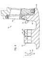
- FIG. 5 is a perspective view of the wheel 62 depicting the balance weight 78 and the groove 76.
- the groove 76 includes a generally flat base 84 surrounded by a pair of tapered sides 86 that converge towards each other away from the base 84.
- the tapered sides 86 may converge towards one another at angles of at least approximately 10, 20, 30, 40, 50, 60, 70, 80, or 90 degrees.
- a slot 88 extends circumferentially 68 along a radially 70 outward portion of the base 84.
- the slot 88 may be disposed along a radially 70 inward portion of the base 84.
- the base 84 may have a width 90 that is generally constant around the circumference of the wheel 62.
- the tapered sides 86 extend axially 66 outward from the base 84 and converge towards one another to form an opening of the groove 76 that has a width 92.
- Width 92 may be smaller than width 90 and may be generally uniform around the circumference of the wheel 62. More specifically, larger access openings are not included around the groove 76.
- the balance weights 78 are inserted into the groove 76 through the opening formed by the tapered sides 86.
- FIG. 5 also depicts the balance weight 78 exploded from the wheel 62 and the groove 76.
- the balance weight 78 may have an asymmetrical circumference extending around the rotational axis (direction 66).
- the balance weight 78 includes a pair of opposite sides 94.
- Each of the sides 94 has a flat section 96 designed to reduce a distance 98 between the sides 94.
- the distance 98 may be approximately equal to or slightly less than the opening width 92. Accordingly, the balance weight 78 may be inserted into the groove 76 through the opening with the flat sections 96 disposed adjacent to the tapered sides 86.
- the balance weight 78 also includes another pair of opposite sides 100 disposed between and extending generally perpendicular to the sides 94.
- Each of the sides 100 may be tapered at an angle corresponding to the tapered sides 86 of the groove 76.
- the sides 100 may be separated by a distance 101 that is greater than the distance 98 separating the sides 94.
- the tapered sides 100 may converge towards one another away from a rear surface 102 of the balance weight 78 at angles of at least approximately 10, 20, 30, 40, 50, 60, 70, 80, or 90 degrees.
- the tapered sides 100 also may include a reverse tapered section where the sides 100 converge towards one another in the opposite direction (e.g., towards the rear surface 102).
- the tapered sides 100 only may converge away from the rear surface 102.
- the balance weight 78 may be inserted into the groove 76 while the tapered sides 100 are generally perpendicular to the tapered sides 86 of the groove 76. After the balance weight 78 is inserted into the groove 76, the weight 78 may be rotated by approximately ninety degrees in the circumferential direction 68 to dispose the sides 100 adjacent to the tapered sides 86 of the groove 76. After rotation, the sides 100 may be generally parallel to the tapered sides 86 of the groove 76. The distance 101 between the sides 100 may be slightly smaller than the base width 90, but larger than the opening width 92 to secure the balance weight 78 within the groove 76 after rotation.
- the balance weight 78 also includes a front surface 104 disposed opposite to the rear surface 102. Upon insertion into the groove 76, the rear surface 102 may be adjacent to the base 84 and the front surface 104 may project from the groove 76.
- the front surface 104 includes a center opening 106 surrounded by a pair of apertures 108. In certain embodiments, the center opening 106 and the apertures 108 may be threaded to receive setscrews and/or an insertion tool for placing and/or securing the balance weight 78 within the groove 76.
- FIG. 6 depicts the balance weight 78 after insertion within the groove 76.
- the balance weight 78 may be inserted by hand within the groove 76, while in other embodiments, an insertion tool, such as a threaded rod, may be inserted into the center opening 106 to facilitate insertion and/or rotation of the balance weight 78 within the groove 76.
- an insertion tool such as a threaded rod
- the base 102 of the balance weight 78 may rest on the base 84 of the groove 76, and the opposing flat sections 96 may be disposed adjacent to the tapered sides 86 of the groove 76.
- the flat sections 96 may be separated by the width 98 that is approximately equal to or slightly smaller than the distance 92 separating the tapered sides 86. The reduced width 98 may allow the balance weight 78 to be inserted into the groove 76 when the flat sections 96 are aligned with the tapered sides 86.
- the balance weight 78 may be rotated approximately ninety degrees in the circumferential direction 68 to dispose the opposite sides 100 adjacent to the tapered sides 86.
- Each of the opposite sides 100 includes a cam surface 110 that is tapered in the circumferential direction 68 about the rotational axis (direction 66).
- the cam surfaces 110 may include rounded corners disposed generally opposite to one another and disposed between the sides 100 and 96.
- the cam surfaces 110 may be tapered in a direction generally perpendicular to the axis of rotation (direction 66).
- the cam surfaces 110 may facilitate rotation of the balance weight 78 within the groove 76.
- the balance weight 78 may be rotated along the cam surfaces 110 to rotate the balance weight approximately 90 degrees about the rotational axis (direction 66).
- the cam surfaces 110 also may be tapered at an angle corresponding to the taper of the opposite sides 100.
- the taper of the opposite sides 100 may extend continuously into the cam surfaces 110. That is, the cam surfaces 110 may be tapered away from the rear surface 102 towards one another at an angle approximately equal to the angles at which the tapered sides 100 converge towards each other. In certain embodiments, the cam surfaces 110 may converge towards one another away from the rear surface 102 (and towards the front surface 104) at angles of at least approximately 10, 20, 30, 40, 50, 60, 70, 80, or 90 degrees.
- FIG. 7 is a cross-sectional view taken along line 7-7 and depicting the balance weight 78 inserted within the groove 76 prior to rotation.
- the rear surface 102 of the balance weight 78 may rest against the base 84 of the groove 76.
- the flat sections 96 are disposed adjacent to the tapered sides 86 with open spaces 112 between the flat sections 96 and the tapered sides 86.
- the flat sections 96 are spaced apart by the distance 98, which is approximately equal to or slightly less than the width 100 between the tapered sides 94. After rotation, the open spaces 112 may be reduced by the greater width 101 existing between the opposite sides 100, shown in FIG. 6 .
- FIG. 8 depicts the balance weight 78 after rotation within the groove 76.
- the opposite sides 100 extend into the groove 76 in the radial direction 70 to approach and/or to contact the tapered sides 86.
- the opposite sides 100 are separated by a width 101 that is greater than the width 92 of the opening to the groove 76, which may serve to retain the balance weight 78 within the groove 76.
- the balance weight 78 may be retained within the groove 76 by a compressive or interference fit where the opposite sides 100 interface with the tapered sides 86.
- the balance weight 78 also may be secured within the groove 76 by inserting fasteners, such as setscrews 114A and 114B, within the apertures 108.
- the setscrews 114A and 114B may include threads 116 designed to mate with threads inside the apertures 108.
- the setscrews 114A and 114B also may include an engagement feature 118, such as an Allen head, slot, socket, Hex key, Phillips key, or the like, for receiving a complementary tool, such as an Allen head wrench, socket wrench, screwdriver, or the like, for driving the setscrews 114A and 114B into the apertures 108.
- the setscrews 114A and 114B may include a gnarled or toothed bottom 120 designed to cut into or engage the base 84 of the groove 76 or the slot 88 within the groove 76.
- the balance weight 78 may be staked within the groove 76.
- the balance weight 78 and the groove 76 may be staked at the locations 122 to deform the surface of the balance weight 78 and/or the groove 76 to secure the groove 76 and the balance weight 78 to one another.
- the balance weight 78 may be secured within the groove 76 without staking.
- the balance weight 78 may be held in place by any combination of staking, setscrews 114A and 114B and/or a compressive fit.
- FIG. 9 is a cross-sectional view taken along line 9-9 and depicting the balance weight 78 inserted within the groove 76 after rotation.
- the opposite sides 100 are adjacent to the tapered sides 86 of the groove 76.
- the sides 100 of the balance weight 78 extend radially (direction 70) into the groove 76 to reduce the size of the open spaces 112 shown in FIG. 7 , to smaller spaces 124.
- the upper setscrew 114A extends into the slot 88 within the groove 76.
- the setscrew 114A may impede further rotation and/or impede reverse rotation of the balance weight 78 within the groove 76.
- the lower setscrew 114B contacts the base 84 of the groove 76.
- the toothed bottom 120 shown in FIG. 8 may engage the base 84 to raise or offset the rear surface 102 of the balance weight 78 from the base 84 of the groove 76.
- the rear surface 102 may be disposed against the base 84.
- the slot 88 may be omitted and both of the setscrews 114A and 114B may engage the base 84 of the groove 76.
- the slot 88 may be located along a portion of the groove 76 that generally aligns with the setscrew 114B. In these embodiments, the setscrew 114B may extend into the slot 88 while the other setscrew 114A engages the base 84.
- FIG. 10 is a front view of another embodiment of the balance weight 78 inserted and rotated within the groove 76.
- the balance weight 78 is generally similar to the balance weight 78 described above with respect to FIGS. 5-9 .
- the opposite sides 100 include recessed portions 126 of a generally concave shape.
- the recessed portions 126 provide two contact points 128 for each side 100 to contact the tapered sides 86.
- the two contact points 128 may distribute the pressure (e.g., centrifugal force when the wheel 62 is rotating) exerted by the balance weight 78 on the tapered sides 86.
- multiple recessed portions 126 may be included within one or both of the opposite sides 100.
- the relative shapes, sizes, and geometries of the balance weight 78 and the groove 76 are provided by way of example only, and are not intended to be limiting.
- the angles of the tapered sides 100 of the balance weight 78 and/or the angles of the tapered sides 86 of the groove 76 may vary from approximately at least 1-90 degrees.
- the curvature of the cam surfaces 110 may vary.
- the relative sizes of the slot 88, the open spaces 112 and 124, the groove 76 and the balance weight 78 may vary depending on factors such as the type of rotary component employed, the type of rotary machine, the operating capacity, and the operating hours, among others.
- the grooves 76 are shown in FIGS. 5-10 in the context of a turbine wheel 62, similar features may exist when the grooves 76 are employed in another rotary component, such as the rotor flange 82 shown in FIG. 4 .
Abstract
Description
- The subject matter disclosed herein relates to balance weights for rotary machines.
- In general, balance weights may be employed in rotary machines, such as gas turbines, steam turbines, generators, and compressors. The balance weights may be used to balance rotating components. For example, the balance weights may be employed to reduce vibrations and/or to compensate for rotational effects of modified or omitted rotary components, such as a bowed rotor or missing or omitted blades or covers. The balance weights may be positioned at various locations along a rotor, wheel, or other rotary component, and may be adjusted at the factory and/or in the field.
- Certain embodiments commensurate in scope with the originally claimed invention are summarized below. These embodiments are not intended to limit the scope of the claimed invention, but rather these embodiments are intended only to provide a brief summary of possible forms of the invention. Indeed, the invention may encompass a variety of forms that may be similar to or different from the embodiments set forth below.
- In a first embodiment, a system includes a rotary machine that has a rotary component with a groove and a balance weight disposed in the groove. The groove includes a base and first tapered sides converging toward one another in a first direction away from the base to form an opening. The balance weight includes a body and second tapered sides converging toward one another in the first direction, and the balance weight is designed to pass through the opening into the groove and rotate to engage the first and second tapered sides.
- In a second embodiment, a system includes a balance weight designed to mount in a groove of a rotary component of a turbine engine. The balance weight includes a base, a rotational axis extending from the base, and a circumference having opposite cam surfaces about the rotational axis. The opposite cam surfaces are at least partially angled toward one another in a direction away from the base along the rotational axis.
- In a third embodiment, a system includes a rotary component with an annular groove with a generally uniform opening and tapered sides converging towards one another from a base of the annular groove to the generally uniform opening. The system also includes a balance weight disposed in the annular groove. The balance weight includes an asymmetrical circumference with a first pair of opposite sides separated by a first width and a second pair of opposite sides separated by a second width greater than the first width. The balance is designed to pass through the generally uniform opening when the first pair of opposite sides are generally parallel to the tapered sides and rotate within the annular groove to dispose the second pair of opposite sides generally parallel to the tapered sides.
- There follows a detailed description of embodiments of the invention by way of example only with reference to the accompanying drawings, in which:
-
FIG. 1 is a schematic flow diagram of an embodiment of a combined cycle power generation system that may employ balance weights; -
FIG. 2 is a cross-sectional view of an embodiment of the steam turbine ofFIG. 1 ; -
FIG. 3 is a cross-sectional view of an embodiment of one of the wheels ofFIG. 2 ; -
FIG. 4 is a cross-sectional view of another embodiment of one of the wheels ofFIG. 2 ; -
FIG. 5 is a perspective view of a wheel with a balance weight exploded from a groove within the wheel; -
FIG. 6 is a perspective view of the wheel ofFIG. 5 with the balance weight inserted in the groove; -
FIG. 7 is a cross-sectional view through the wheel ofFIG. 6 taken along line 7-7; -
FIG. 8 is a perspective view of the wheel ofFIG. 5 with the balance weight rotated within the groove; -
FIG. 9 is a cross-sectional view through the wheel ofFIG. 8 taken along line 9-9; and -
FIG. 10 is a front view of the wheel ofFIG. 5 depicting another embodiment of the balance weight rotated within the groove. - One or more specific embodiments of the present invention will be described below. In an effort to provide a concise description of these embodiments, all features of an actual implementation may not be described in the specification. It should be appreciated that in the development of any such actual implementation, as in any engineering or design project, numerous implementation-specific decisions must be made to achieve the developers' specific goals, such as compliance with system-related and business-related constraints, which may vary from one implementation to another. Moreover, it should be appreciated that such a development effort might be complex and time consuming, but would nevertheless be a routine undertaking of design, fabrication, and manufacture for those of ordinary skill having the benefit of this disclosure.
- When introducing elements of various embodiments of the present invention, the articles "a," "an," "the," and "said" are intended to mean that there are one or more of the elements. The terms "comprising," "including," and "having" are intended to be inclusive and mean that there may be additional elements other than the listed elements.
- The present disclosure is directed to balance weights for rotary machines, such as gas turbines, steam turbines, wind turbines, hydro turbines, compressors, and generators. In general, balance weights may be positioned within rotary components of the rotary machines to balance the rotary components during operation. The balance weights may include two sets of opposing sides separated by cam surfaces. The first set of opposing sides may be separated by a smaller width and the second set of opposing sides may be separated by a larger width. The different widths may allow the balance weights to be inserted at any location along a groove within a rotary component. For example, the groove may include tapered sides converging towards one another to form an opening smaller than the base of the groove. The smaller width of the balance weight may be approximately equal to or smaller than the groove opening. Accordingly, the first set of opposing sides may be aligned with the tapered sides to insert the balance weight into the groove. After insertion, the balance weight may be rotated approximately ninety degrees within the groove to align the second opposite sides with the tapered sides of the groove. The second opposite sides may generally extend into the groove beyond the opening to retain the balance weight within the groove. Accordingly, the balance weights may be inserted and positioned within the groove at any location along the groove. That is, no separate openings, holes, or local engagement features need to be provided at locations along the groove to allow insertion of the balance weights. Moreover, rather than providing tapped holes for balance weights that are inserted into specific openings (i.e. plug or gate type balance weights), the grooves may be machined into the rotary components, which in turn may reduce machining cycles, times, and/or manufacturing costs.
-
FIG. 1 is a schematic flow diagram of an embodiment of a combined cyclepower generation system 10 that may employ balance weights. Thesystem 10 may include agas turbine 12, a steam turbine 14, and a heat recovery steam generation (HRSG)system 16. Within the gas turbine 14, gas, such as syngas, may be combusted to generate power within a "topping," or Brayton, cycle. Exhaust gas from the gas turbine 14 may be supplied to theHRSG system 16 to generate steam within a "bottoming," or Rankine, cycle. In certain embodiments, thegas turbine 12, the steam turbine 14, and the HRSGsystem 16 may be included within an integrated gasification combined cycle (IGCC) power plant. - The
gas turbine 12 may generally combust a fuel (e.g., liquid and/or gas fuel) to drive afirst load 18. Thefirst load 18 may, for instance, be an electrical generator for producing electrical power. Thegas turbine 12 may include aturbine 20, a combustor orcombustion chamber 22, and acompressor 24.Exhaust gas 26 from thegas turbine 20 may be used to generate steam supplied to steam turbine 14 (through the HRSG system 16) for driving asecond load 28. Thesecond load 28 also may be an electrical generator for generating electrical power. However, both the first andsecond loads gas turbine 12 and steam turbine 14. Further, although thegas turbine 12 and steam turbine 14 are depicted as drivingseparate loads gas turbine 12 and steam turbine 14 also may be utilized in tandem to drive a single load via a single shaft. In the illustrated embodiment, the steam turbine 14 may include one low-pressure section 30 (LP ST), one intermediate-pressure section 32 (IP ST), and one high-pressure section 34 (HP ST). However, the specific configuration of the steam turbine 14, as well as thegas turbine 12, may be implementation-specific and may include any combination of sections. - The
system 10 also includes theHRSG system 16 for employing heat from thegas turbine 12 to generate steam for the steam turbine 14. TheHRSG system 16 may include components such as evaporators, economizers, heaters, superheaters, and attemperators, among others, that are used to generate a high-pressure, high-temperature steam. The steam produced by theHRSG system 16 may be supplied to the low-pressure section 30, theintermediate pressure section 32, and the high-pressure section 34 of the steam turbine 14 for power generation. Exhaust from the low-pressure section 30 may be directed into acondenser 36. Condensate from thecondenser 36 may, in turn, be returned to theHRSG system 16 with the aid of acondensate pump 38. Within theHRSG system 16, the condensate may then be reheated to generate steam for the steam turbine 14. - The balance weights may be used to balance rotary components within the combined
cycle system 10. For example, the balance weights may be used in thegas turbine 12, thecompressor 24, the steam turbine 14, and/or in theHRSG system 16. In other embodiments, the balance weights may be used in independent rotary machines. For example, the balance weights may be used in a gas turbine, steam turbine, compressor, or generator that is part of a simple cycle system. Moreover, the balance weights may be employed in other types of rotary machines, such as wind turbines and hydro turbines. -
FIG. 2 depicts an embodiment of the steam turbine 14 that includes the high-pressure-section 34, the intermediate-pressure section 32, and the low-pressure section 30 ofFIG. 1 . The steam turbine 14 includes a mainsteam inlet port 40 that may receive steam, for example, from theHRSG system 16 ofFIG. 1 . The steam may flow through a series ofstages 42. In general, eachstage 42 may include circumferentially spaced blades mounted to a wheel encircling ashaft 44 that rotates about anaxis 46. From the high-pressure section 34, the steam may enter the intermediate-pressure section 32 and flow through another series ofstages 48, each including circumferentially spaced blades mounted to a wheel encircling theshaft 44. In certain embodiments, the steam may undergo heating before flowing into the intermediate-pressure section 32. - From the intermediate-
pressure section 32, the steam may flow to the low-pressure section 30 through acrossover pipe 50 and aninlet box 52. Within the low-pressure section 30, the steam may flow in opposite axial directions through a series ofstages 54, each including circumferentially spaced blades mounted to a wheel encircling ashaft 56 that rotates about theaxis 46. Theshaft 56 may includeflanges 58 disposed on axially opposite ends to couple theshaft 56 to theshaft 44 on one end, and to couple theshaft 56 to a generator shaft (not shown) on the other end. In certain embodiments, balance weights may be included on theflanges 58 and/or on the wheels within thestages -
FIG. 3 is a cross-sectional view of a portion of one of the low-pressure stages 54 taken within line 3-3 ofFIG. 2 . Awheel 62 may be mounted to and may encircle theshaft 56. Although only onewheel 62 is shown, in certain embodiments,multiple wheels 62 may be axially spaced (direction 66) along theshaft 56. Eachwheel 62 may extend circumferentially (direction 68) around theshaft 56. A series ofblades 64 may extend radially (direction 70) from thewheel 62 and may be circumferentially 68 spaced around thewheel 62. Thewheel 62 may include axially 66 opposite faces 72 and 74, each containing agroove 76 for receivingbalance weights 78. Thegrooves 76 may extend circumferentially 68 in whole or in part around thewheel 62. For example, eachgroove 76 may include a single, continuous and annular groove disposed 360-degrees about theshaft 56, or eachgroove 76 may include multiple short grooves in a segmented manner about theshaft 56. Thegrooves 76 may extend in a plane generally parallel to the radial direction (e.g., thegroove 76 in axial face 72), and/or thegrooves 76 may be inclined with respect to the radial direction (e.g., thegroove 76 in axial face 74). Thebalance weights 78 may be disposed at various circumferential 68 locations around thegrooves 76. Moreover, in certain embodiments, thebalance weights 78 may be repositioned, removed, or added to balance thewheel 62. -
FIG. 4 is a cross-sectional view of another embodiment of a portion of the low-pressure stage 54. Awheel 80 extends circumferentially 68 around theshaft 56 and includes the axial faces 72 and 74. However, in this embodiment, thegroove 76 is disposed on one of the faces 72. Thegroove 76 includes one ormore balance weights 78. In other embodiments,grooves 76 may be included in one or both of the axial faces 72 and 74. Moreover, the axial faces 72 and 74 may extend parallel to or at various angles with respect to theradial direction 70. - A
rotor flange 82 also extends radially 70 from theshaft 56. As noted above with respect toFIG. 2 , therotor flange 82 may be used to couple multiple shafts together. Therotor flange 82 includesgrooves 76 that extend circumferentially 68 about theshaft 56. Although a pair ofgrooves 76 is shown, any number ofgrooves 76 may be included within therotor flange 82. One ormore balance weights 76 may be positioned in thegrooves 76 to balance theshaft 56. As shown, thegrooves 76 encircle theshaft 56 and include openings extending in theradial direction 70. However, in other embodiments, the grooves may encircle theshaft 56 and have openings extending in theaxial direction 66, for example, in a manner similar to thegroove 76 disposed on thewheel 80. -
FIG. 5 is a perspective view of thewheel 62 depicting thebalance weight 78 and thegroove 76. Thegroove 76 includes a generallyflat base 84 surrounded by a pair of taperedsides 86 that converge towards each other away from thebase 84. In certain embodiments, the taperedsides 86 may converge towards one another at angles of at least approximately 10, 20, 30, 40, 50, 60, 70, 80, or 90 degrees. Aslot 88 extends circumferentially 68 along a radially 70 outward portion of thebase 84. However, in other embodiments, theslot 88 may be disposed along a radially 70 inward portion of thebase 84. The base 84 may have awidth 90 that is generally constant around the circumference of thewheel 62. The tapered sides 86 extend axially 66 outward from thebase 84 and converge towards one another to form an opening of thegroove 76 that has awidth 92.Width 92 may be smaller thanwidth 90 and may be generally uniform around the circumference of thewheel 62. More specifically, larger access openings are not included around thegroove 76. Thebalance weights 78 are inserted into thegroove 76 through the opening formed by the tapered sides 86. -
FIG. 5 also depicts thebalance weight 78 exploded from thewheel 62 and thegroove 76. Thebalance weight 78 may have an asymmetrical circumference extending around the rotational axis (direction 66). Specifically, thebalance weight 78 includes a pair ofopposite sides 94. Each of thesides 94 has aflat section 96 designed to reduce adistance 98 between thesides 94. Thedistance 98 may be approximately equal to or slightly less than theopening width 92. Accordingly, thebalance weight 78 may be inserted into thegroove 76 through the opening with theflat sections 96 disposed adjacent to the tapered sides 86. - The
balance weight 78 also includes another pair ofopposite sides 100 disposed between and extending generally perpendicular to thesides 94. Each of thesides 100 may be tapered at an angle corresponding to the taperedsides 86 of thegroove 76. Thesides 100 may be separated by adistance 101 that is greater than thedistance 98 separating thesides 94. In certain embodiments, the taperedsides 100 may converge towards one another away from arear surface 102 of thebalance weight 78 at angles of at least approximately 10, 20, 30, 40, 50, 60, 70, 80, or 90 degrees. Moreover, in certain embodiments, the taperedsides 100 also may include a reverse tapered section where thesides 100 converge towards one another in the opposite direction (e.g., towards the rear surface 102). However, in other embodiments, the taperedsides 100 only may converge away from therear surface 102. - The
balance weight 78 may be inserted into thegroove 76 while the taperedsides 100 are generally perpendicular to the taperedsides 86 of thegroove 76. After thebalance weight 78 is inserted into thegroove 76, theweight 78 may be rotated by approximately ninety degrees in thecircumferential direction 68 to dispose thesides 100 adjacent to the taperedsides 86 of thegroove 76. After rotation, thesides 100 may be generally parallel to the taperedsides 86 of thegroove 76. Thedistance 101 between thesides 100 may be slightly smaller than thebase width 90, but larger than theopening width 92 to secure thebalance weight 78 within thegroove 76 after rotation. - The
balance weight 78 also includes afront surface 104 disposed opposite to therear surface 102. Upon insertion into thegroove 76, therear surface 102 may be adjacent to thebase 84 and thefront surface 104 may project from thegroove 76. Thefront surface 104 includes acenter opening 106 surrounded by a pair ofapertures 108. In certain embodiments, thecenter opening 106 and theapertures 108 may be threaded to receive setscrews and/or an insertion tool for placing and/or securing thebalance weight 78 within thegroove 76. -
FIG. 6 depicts thebalance weight 78 after insertion within thegroove 76. In certain embodiments, thebalance weight 78 may be inserted by hand within thegroove 76, while in other embodiments, an insertion tool, such as a threaded rod, may be inserted into thecenter opening 106 to facilitate insertion and/or rotation of thebalance weight 78 within thegroove 76. Upon insertion, thebase 102 of thebalance weight 78 may rest on thebase 84 of thegroove 76, and the opposingflat sections 96 may be disposed adjacent to the taperedsides 86 of thegroove 76. Theflat sections 96 may be separated by thewidth 98 that is approximately equal to or slightly smaller than thedistance 92 separating the tapered sides 86. The reducedwidth 98 may allow thebalance weight 78 to be inserted into thegroove 76 when theflat sections 96 are aligned with the tapered sides 86. - After insertion, the
balance weight 78 may be rotated approximately ninety degrees in thecircumferential direction 68 to dispose theopposite sides 100 adjacent to the tapered sides 86. Each of theopposite sides 100 includes acam surface 110 that is tapered in thecircumferential direction 68 about the rotational axis (direction 66). The cam surfaces 110 may include rounded corners disposed generally opposite to one another and disposed between thesides balance weight 78 within thegroove 76. For example, thebalance weight 78 may be rotated along the cam surfaces 110 to rotate the balance weight approximately 90 degrees about the rotational axis (direction 66). - The cam surfaces 110 also may be tapered at an angle corresponding to the taper of the
opposite sides 100. In certain embodiments, the taper of theopposite sides 100 may extend continuously into the cam surfaces 110. That is, the cam surfaces 110 may be tapered away from therear surface 102 towards one another at an angle approximately equal to the angles at which the taperedsides 100 converge towards each other. In certain embodiments, the cam surfaces 110 may converge towards one another away from the rear surface 102 (and towards the front surface 104) at angles of at least approximately 10, 20, 30, 40, 50, 60, 70, 80, or 90 degrees. -
FIG. 7 is a cross-sectional view taken along line 7-7 and depicting thebalance weight 78 inserted within thegroove 76 prior to rotation. Therear surface 102 of thebalance weight 78 may rest against thebase 84 of thegroove 76. Theflat sections 96 are disposed adjacent to the taperedsides 86 withopen spaces 112 between theflat sections 96 and the tapered sides 86. Theflat sections 96 are spaced apart by thedistance 98, which is approximately equal to or slightly less than thewidth 100 between the tapered sides 94. After rotation, theopen spaces 112 may be reduced by thegreater width 101 existing between theopposite sides 100, shown inFIG. 6 . -
FIG. 8 depicts thebalance weight 78 after rotation within thegroove 76. Theopposite sides 100 extend into thegroove 76 in theradial direction 70 to approach and/or to contact the tapered sides 86. Theopposite sides 100 are separated by awidth 101 that is greater than thewidth 92 of the opening to thegroove 76, which may serve to retain thebalance weight 78 within thegroove 76. For example, thebalance weight 78 may be retained within thegroove 76 by a compressive or interference fit where theopposite sides 100 interface with the tapered sides 86. - After rotation, the
balance weight 78 also may be secured within thegroove 76 by inserting fasteners, such assetscrews apertures 108. Thesetscrews threads 116 designed to mate with threads inside theapertures 108. Thesetscrews engagement feature 118, such as an Allen head, slot, socket, Hex key, Phillips key, or the like, for receiving a complementary tool, such as an Allen head wrench, socket wrench, screwdriver, or the like, for driving thesetscrews apertures 108. Opposite to theengagement feature 118, thesetscrews toothed bottom 120 designed to cut into or engage thebase 84 of thegroove 76 or theslot 88 within thegroove 76. Instead of, or in addition to, using thesetscrews balance weight 78 may be staked within thegroove 76. For example, thebalance weight 78 and thegroove 76 may be staked at thelocations 122 to deform the surface of thebalance weight 78 and/or thegroove 76 to secure thegroove 76 and thebalance weight 78 to one another. However, in other embodiments, thebalance weight 78 may be secured within thegroove 76 without staking. Further, thebalance weight 78 may be held in place by any combination of staking, setscrews 114A and 114B and/or a compressive fit. -
FIG. 9 is a cross-sectional view taken along line 9-9 and depicting thebalance weight 78 inserted within thegroove 76 after rotation. Theopposite sides 100 are adjacent to the taperedsides 86 of thegroove 76. As seen by comparingFIGS. 7 and9 , after rotation, thesides 100 of thebalance weight 78 extend radially (direction 70) into thegroove 76 to reduce the size of theopen spaces 112 shown inFIG. 7 , tosmaller spaces 124. Theupper setscrew 114A extends into theslot 88 within thegroove 76. Thesetscrew 114A may impede further rotation and/or impede reverse rotation of thebalance weight 78 within thegroove 76. Thelower setscrew 114B contacts thebase 84 of thegroove 76. Specifically, thetoothed bottom 120 shown inFIG. 8 may engage the base 84 to raise or offset therear surface 102 of thebalance weight 78 from thebase 84 of thegroove 76. However, in other embodiments, therear surface 102 may be disposed against thebase 84. Further, in certain embodiments, theslot 88 may be omitted and both of thesetscrews base 84 of thegroove 76. Moreover, in other embodiments, theslot 88 may be located along a portion of thegroove 76 that generally aligns with thesetscrew 114B. In these embodiments, thesetscrew 114B may extend into theslot 88 while theother setscrew 114A engages thebase 84. -
FIG. 10 is a front view of another embodiment of thebalance weight 78 inserted and rotated within thegroove 76. Thebalance weight 78 is generally similar to thebalance weight 78 described above with respect toFIGS. 5-9 . However, theopposite sides 100 include recessedportions 126 of a generally concave shape. The recessedportions 126 provide twocontact points 128 for eachside 100 to contact the tapered sides 86. The twocontact points 128 may distribute the pressure (e.g., centrifugal force when thewheel 62 is rotating) exerted by thebalance weight 78 on the tapered sides 86. In other embodiments, multiple recessedportions 126 may be included within one or both of theopposite sides 100. - The relative shapes, sizes, and geometries of the
balance weight 78 and thegroove 76 are provided by way of example only, and are not intended to be limiting. For example, the angles of the taperedsides 100 of thebalance weight 78 and/or the angles of the taperedsides 86 of thegroove 76 may vary from approximately at least 1-90 degrees. In another example, the curvature of the cam surfaces 110 may vary. Moreover, the relative sizes of theslot 88, theopen spaces groove 76 and thebalance weight 78 may vary depending on factors such as the type of rotary component employed, the type of rotary machine, the operating capacity, and the operating hours, among others. Further, although thegrooves 76 are shown inFIGS. 5-10 in the context of aturbine wheel 62, similar features may exist when thegrooves 76 are employed in another rotary component, such as therotor flange 82 shown inFIG. 4 . - This written description uses examples to disclose the invention, including the best mode, and also to enable any person skilled in the art to practice the invention, including making and using any devices or systems and performing any incorporated methods. The patentable scope of the invention is defined by the claims, and may include other examples that occur to those skilled in the art. Such other examples are intended to be within the scope of the claims if they have structural elements that do not differ from the literal language of the claims, or if they include equivalent structural elements with insubstantial differences from the literal languages of the claims.
- For completeness, various aspects of the invention are now set out in the following numbered clauses:
- 1. A system, comprising:
- a rotary machine, comprising:
- a rotary component comprising a groove having a base and first tapered sides converging toward one another in a first direction away from the base to form an opening; and
- a balance weight disposed in the groove, wherein the balance weight comprises a body and second tapered sides converging toward one another in the first direction, wherein the balance weight is configured to pass through the opening into the groove and rotate to engage the first and second tapered sides.
- a rotary machine, comprising:
- 2. The system of
clause 1, wherein the balance weight comprises opposite cam surfaces about a rotational axis of the balance weight, and wherein the cam surfaces are configured to rotate the second tapered sides from a first position generally perpendicular to the first tapered sides to a second position generally parallel to the first tapered sides. - 3. The system of
clause 1, wherein the second tapered sides converge toward one another in the first direction along a rotational axis of the balance weight, the balance weight has an asymmetrical circumference about the rotational axis, the asymmetrical circumference comprises opposite curved surfaces circumferentially between opposite first surfaces and opposite second surfaces, and the opposite first surfaces are offset by a first distance less than a second distance between the opposite second surfaces. - 4. The system of clause 3, wherein the first distance is less than a width of the opening and the second distance is greater than the width of the opening.
- 5. The system of
clause 1, wherein the body of the balance weight comprises at least one aperture extending therethrough and configured to receive a fastener to secure the balance weight to the groove. - 6. The system of clause 5, comprising the fastener disposed in the aperture to offset a rear surface of the balance weight from the base of the groove.
- 7. The system of clause 5, wherein the groove comprises a slot in the base and wherein the slot is configured to receive the fastener to inhibit rotation of the balance weight.
- 8. The system of
clause 1, wherein the balance weight is secured within the groove without staking. - 9. The system of
clause 1, wherein the opening has a uniform width throughout the groove. - 10. The system of
clause 1, wherein the rotary machine comprises a compressor, a generator, a gas turbine, a steam turbine, a wind turbine, a hydro turbine, or a combination thereof. - 11. A system, comprising:
- a balance weight configured to mount in a groove of a rotary component of a turbine engine, wherein the balance weight comprises a base, a rotational axis extending from the base, and a circumference having opposite cam surfaces about the rotational axis, wherein the opposite cam surfaces are at least partially angled toward one another in a direction away from the base along the rotational axis.
- 12. The system of clause 11, wherein the balance weight is configured to pass into the groove at a first position and rotate within the groove along the opposite cam surfaces to gradually compress the balance weight in the groove at a second position approximately 90 degrees about the rotational axis from the first position.
- 13. The system of clause 11, wherein the balance weight comprises a first pair of opposite flat sides separated by a first width and a second pair of opposite tapered sides separated by a second width greater than the first width, wherein each of the opposite cam surfaces is disposed between one of the flat sides and one of the tapered sides along the circumference.
- 14. The system of clause 13, wherein the opposite tapered sides converge towards one another away from the base at angles of approximately 10-50 degrees and wherein the angles are generally parallel to corresponding angled surfaces of the groove.
- 15. The system of clause 13, wherein at least one of the opposite tapered sides comprises a recess extending along the circumference to create multiple contact points between the at least one opposite tapered side and the groove.
- 16. The system of clause 13, wherein the opposite cam surfaces and the opposite tapered sides converge at substantially the same angle.
- 17. The system of clause 11, comprising a turbine rotor, wherein the groove is disposed in a flange of the turbine rotor or in a turbine wheel encircling the turbine rotor.
- 18. A system, comprising:
- a rotary component comprising an annular groove with a generally uniform opening and tapered sides converging towards one another from a base of the annular groove to the generally uniform opening; and
- a balance weight disposed in the annular groove, wherein the balance weight comprises an asymmetrical circumference with a first pair of opposite sides separated by a first width and a second pair of opposite sides separated by a second width greater than the first width, and wherein the balance is configured to pass through the generally uniform opening when the first pair of opposite sides are generally parallel to the tapered sides and rotate within the annular groove to dispose the second pair of opposite sides generally parallel to the tapered sides.
- 19. The system of
clause 18, wherein the asymmetrical circumference comprises opposite cam surfaces configured to rotate the balance weight within the annular groove. - 20. The system of
clause 18, wherein the system comprises a turbine engine.
Claims (15)
- A system, comprising:a rotary machine (12, 14, 24), comprising:a rotary component (62) comprising a groove (76) having a base (84) and first tapered sides (86) converging toward one another in a first direction (66) away from the base (84) to form an opening; anda balance weight (78) disposed in the groove (76), wherein the balance weight (78) comprises a body and second tapered sides (100) converging toward one another in the first direction (66), wherein the balance weight is configured to pass through the opening into the groove (76) and rotate to engage the first and second tapered sides (86, 100).
- The system of claim 1, wherein the balance weight (78) comprises opposite cam surfaces (110) about a rotational axis of the balance weight (78), and wherein the cam surfaces (110) are configured to rotate the second tapered sides (100) from a first position generally perpendicular to the first tapered sides (86) to a second position generally parallel to the first tapered sides (86).
- The system of claim 1 or 2, wherein the second tapered sides (100) converge toward one another in the first direction (66) along a rotational axis of the balance weight, the balance weight has an asymmetrical circumference about the rotational axis, the asymmetrical circumference comprises opposite curved surfaces circumferentially between opposite first surfaces (96) and opposite second surfaces (100), and the opposite first surfaces (96) are offset by a first distance (98) less than a second distance (100) between the opposite second surfaces.
- The system of claim 3, wherein the first distance (98) is less than a width (92) of the opening and the second distance (100) is greater than the width (92) of the opening.
- The system of any of the preceding claims, wherein the body of the balance weight comprises at least one aperture (108) extending therethrough and configured to receive a fastener (114) to secure the balance weight (78) to the groove (76).
- The system of claim 5, comprising the fastener (114) disposed in the aperture (108) to offset a rear surface (102) of the balance weight (78) from the base (84) of the groove (76).
- The system of claim 5, wherein the groove (76) comprises a slot (88) in the base (84) and wherein the slot (88) is configured to receive the fastener (114) to inhibit rotation of the balance weight (78).
- The system of any of the preceding claims, wherein the balance weight (78) is secured within the groove (76) without staking.
- The system of any of the preceding claims, wherein the opening has a uniform width (92) throughout the groove (76).
- The system of any of the preceding claims, wherein the rotary machine comprises a compressor, a generator, a gas turbine, a steam turbine, a wind turbine, a hydro turbine, or a combination thereof.
- A system, comprising:a balance weight (78) configured to mount in a groove (76) of a rotary component (62) of a turbine engine (12, 14), wherein the balance weight (78) comprises a base (84), a rotational axis extending from the base, and a circumference having opposite cam surfaces (110) about the rotational axis, wherein the opposite cam surfaces (110) are at least partially angled toward one another in a direction away from the base (84) along the rotational axis.
- The system of clause 11, wherein the balance weight is configured to pass into the groove at a first position and rotate within the groove along the opposite cam surfaces to gradually compress the balance weight in the groove at a second position approximately 90 degrees about the rotational axis from the first position.
- The system of claim 10 or 12, wherein the balance weight comprises a first pair of opposite flat sides separated by a first width and a second pair of opposite tapered sides separated by a second width greater than the first width, wherein each of the opposite cam surfaces is disposed between one of the flat sides and one of the tapered sides along the circumference.
- The system of claim 13, wherein the opposite tapered sides converge towards one another away from the base at angles of approximately 10-50 degrees and wherein the angles are generally parallel to corresponding angled surfaces of the groove.
- The system of claim 13 or 14, wherein at least one of the opposite tapered sides comprises a recess extending along the circumference to create multiple contact points between the at least one opposite tapered side and the groove.
Applications Claiming Priority (1)
| Application Number | Priority Date | Filing Date | Title |
|---|---|---|---|
| US12/435,324 US8177487B2 (en) | 2009-05-04 | 2009-05-04 | Rotary machine balance weights |
Publications (2)
| Publication Number | Publication Date |
|---|---|
| EP2251529A2 true EP2251529A2 (en) | 2010-11-17 |
| EP2251529A3 EP2251529A3 (en) | 2013-10-16 |
Family
ID=42321185
Family Applications (1)
| Application Number | Title | Priority Date | Filing Date |
|---|---|---|---|
| EP10161477.4A Withdrawn EP2251529A3 (en) | 2009-05-04 | 2010-04-29 | Rotary machine balance weights |
Country Status (4)
| Country | Link |
|---|---|
| US (1) | US8177487B2 (en) |
| EP (1) | EP2251529A3 (en) |
| JP (1) | JP5523920B2 (en) |
| RU (1) | RU2535897C2 (en) |
Cited By (3)
| Publication number | Priority date | Publication date | Assignee | Title |
|---|---|---|---|---|
| CN104514840A (en) * | 2013-09-30 | 2015-04-15 | 哈尔滨飞机工业集团有限责任公司 | Airplane counterweight device |
| EP2545252B1 (en) * | 2010-06-17 | 2019-02-20 | Siemens Aktiengesellschaft | Balance correction weight providing constant mass |
| EP3971387A1 (en) * | 2020-09-16 | 2022-03-23 | General Electric Company | Balancing weight entry port for turbine rotor |
Families Citing this family (21)
| Publication number | Priority date | Publication date | Assignee | Title |
|---|---|---|---|---|
| EP2405100A1 (en) * | 2010-07-05 | 2012-01-11 | Siemens Aktiengesellschaft | Combined sealing and balancing arrangement for a turbine disc |
| JP5812766B2 (en) * | 2011-08-29 | 2015-11-17 | ミネベア株式会社 | Blower |
| WO2013162122A1 (en) * | 2012-04-23 | 2013-10-31 | 주식회사 제이엠더블유 | Bldc motor having sintered bearings for hair dryer |
| JP2013253522A (en) * | 2012-06-06 | 2013-12-19 | Ihi Corp | Blisk |
| EP2708697A1 (en) * | 2012-09-17 | 2014-03-19 | Alstom Technology Ltd | Method of coupling two rotor sections and turbine rotor |
| JP6131022B2 (en) * | 2012-10-30 | 2017-05-17 | 三菱重工業株式会社 | Impeller and rotating machine equipped with the same |
| US9404367B2 (en) | 2012-11-21 | 2016-08-02 | Solar Turbines Incorporated | Gas turbine engine compressor rotor assembly and balancing system |
| KR200486080Y1 (en) * | 2013-03-25 | 2018-03-30 | 대우조선해양 주식회사 | Apparatus for auto balancing of grinder |
| US9518610B2 (en) * | 2013-05-28 | 2016-12-13 | General Electric Company | Load coupling and method for adjusting torsional natural frequency of power train |
| US10247003B2 (en) | 2013-09-26 | 2019-04-02 | United Technologies Corporation | Balanced rotating component for a gas powered engine |
| US20150192019A1 (en) * | 2014-01-07 | 2015-07-09 | General Electric Company | Rotor train torsional mode frequency tuning apparatus |
| EP2905109A1 (en) * | 2014-02-07 | 2015-08-12 | Siemens Aktiengesellschaft | Method and device for securing a threaded element that is screwed into a thread seat a threaded element, method for installing at least one balancing weight of a turbine and turbine |
| US9917488B2 (en) * | 2014-03-04 | 2018-03-13 | Nidec Motor Corporation | Motor including removable weights for balancing |
| CN104929980B (en) * | 2015-07-03 | 2018-07-17 | 广东海洋大学 | A kind of fan leaf having dynamic balancing self-reacting device |
| KR101789907B1 (en) * | 2016-01-11 | 2017-10-25 | 두산중공업 주식회사 | Gas turbine |
| US11105203B2 (en) * | 2018-01-29 | 2021-08-31 | Carrier Corporation | High efficiency centrifugal impeller with balancing weights |
| US10883370B2 (en) * | 2018-08-14 | 2021-01-05 | Raytheon Technologies Corporation | Dovetail weight system for rotor balance |
| JP7196120B2 (en) * | 2020-02-10 | 2022-12-26 | 三菱重工業株式会社 | turbine wheel |
| KR102348487B1 (en) * | 2020-06-24 | 2022-01-06 | 두산중공업 주식회사 | Turbine blade and gas turbine comprising the same |
| KR102360887B1 (en) * | 2021-02-16 | 2022-02-08 | 한전케이피에스 주식회사 | Weight device for Generator turbine balancing |
| KR20230091604A (en) * | 2021-12-16 | 2023-06-23 | 한화에어로스페이스 주식회사 | Rotor assembly with protection shim and gas turbine engine including the same |
Family Cites Families (14)
| Publication number | Priority date | Publication date | Assignee | Title |
|---|---|---|---|---|
| GB805371A (en) * | 1956-01-16 | 1958-12-03 | Rolls Royce | Improvements in or relating to balancing means for rotors |
| SU385373A1 (en) * | 1970-12-18 | 1973-05-29 | DEVICE FOR CLAMINATING THE ROSES OF A TURBO-GENERATOR ROTOR | |
| US3736811A (en) * | 1971-08-19 | 1973-06-05 | Gen Electric | Balance weight attachment for turbine wheels |
| JPS5913740U (en) * | 1982-07-16 | 1984-01-27 | 富士電機株式会社 | Balance weight of rotating body |
| US4477226A (en) * | 1983-05-09 | 1984-10-16 | General Electric Company | Balance for rotating member |
| US4842485A (en) * | 1988-02-10 | 1989-06-27 | Westinghouse Electric Corp. | Balanced turbine rotor and method for making the same |
| SU1620869A1 (en) * | 1989-02-08 | 1991-01-15 | Университет дружбы народов им.Патриса Лумумбы | Balancing device |
| US5018943A (en) * | 1989-04-17 | 1991-05-28 | General Electric Company | Boltless balance weight for turbine rotors |
| US6481969B2 (en) * | 1999-05-10 | 2002-11-19 | General Electric Company | Apparatus and methods for balancing turbine rotors |
| US6279420B1 (en) * | 1999-08-18 | 2001-08-28 | General Electric Co. | Balance weight for a rotary component in turbomachinery, methods of installation and installation tools |
| US20050265846A1 (en) * | 2004-06-01 | 2005-12-01 | Przytulski James C | Balance assembly for rotary turbine component and method for installing and/or adjusting balance weight |
| US7234916B2 (en) * | 2004-09-16 | 2007-06-26 | General Electric Company | Method and apparatus for balancing gas turbine engines |
| US7371042B2 (en) * | 2004-12-21 | 2008-05-13 | General Electric Company | Method and apparatus for balancing gas turbine engines |
| US7465146B2 (en) * | 2005-12-05 | 2008-12-16 | General Electric Company | Methods and systems for turbine rotor balancing |
-
2009
- 2009-05-04 US US12/435,324 patent/US8177487B2/en not_active Expired - Fee Related
-
2010
- 2010-04-27 JP JP2010101581A patent/JP5523920B2/en not_active Expired - Fee Related
- 2010-04-29 EP EP10161477.4A patent/EP2251529A3/en not_active Withdrawn
- 2010-04-30 RU RU2010117015/06A patent/RU2535897C2/en not_active IP Right Cessation
Non-Patent Citations (1)
| Title |
|---|
| None |
Cited By (5)
| Publication number | Priority date | Publication date | Assignee | Title |
|---|---|---|---|---|
| EP2545252B1 (en) * | 2010-06-17 | 2019-02-20 | Siemens Aktiengesellschaft | Balance correction weight providing constant mass |
| CN104514840A (en) * | 2013-09-30 | 2015-04-15 | 哈尔滨飞机工业集团有限责任公司 | Airplane counterweight device |
| EP3971387A1 (en) * | 2020-09-16 | 2022-03-23 | General Electric Company | Balancing weight entry port for turbine rotor |
| US11377955B2 (en) | 2020-09-16 | 2022-07-05 | General Electric Company | Balancing weight entry port for turbine rotor |
| US11846201B2 (en) | 2020-09-16 | 2023-12-19 | General Electric Company | Balancing weight entry port for turbine rotor |
Also Published As
| Publication number | Publication date |
|---|---|
| RU2535897C2 (en) | 2014-12-20 |
| JP2010261446A (en) | 2010-11-18 |
| EP2251529A3 (en) | 2013-10-16 |
| RU2010117015A (en) | 2011-11-10 |
| US8177487B2 (en) | 2012-05-15 |
| JP5523920B2 (en) | 2014-06-18 |
| US20100278634A1 (en) | 2010-11-04 |
Similar Documents
| Publication | Publication Date | Title |
|---|---|---|
| US8177487B2 (en) | Rotary machine balance weights | |
| EP2386724A2 (en) | Rotary machine with a labyrinth seal with curved teeth | |
| JP5604512B2 (en) | Engaging spring counterweight and rotor assembly | |
| KR101643476B1 (en) | Bucket assembly for replacing old bucket provided with turbine and method thereof | |
| US8651820B2 (en) | Dovetail connection for turbine rotating blade and rotor wheel | |
| JP6408888B2 (en) | Turbine bucket closing assembly and its assembling method | |
| US9051845B2 (en) | System for axial retention of rotating segments of a turbine | |
| EP2246598A1 (en) | Packing seal rotor lands | |
| JP2018513299A (en) | Multi-stage turbine for preferably an organic Rankine cycle ORC plant | |
| US20190226347A1 (en) | Vane ring assembly, method of assembling the same, and gas turbine including the same | |
| US20090081030A1 (en) | Bolt assembly for steam turbine engines and method of assembling the same | |
| CN104712374A (en) | Rotor wheel assembly and assembling method thereof and corresponding turbine engine | |
| EP2270316A2 (en) | System for aligning turbine components | |
| JP2009036062A (en) | Turbo machine rotor | |
| US9334737B2 (en) | Balance weight installation system and related method | |
| US9896946B2 (en) | Gas turbine engine rotor assembly and method of assembling the same | |
| US20130259678A1 (en) | System and Method for Coupling Rotor Components | |
| US9422820B2 (en) | Method and system for self-locking a closure bucket in a rotary machine | |
| US20180187711A1 (en) | Locking nut and bolt assemblies for reducing windage in the vicinity of a high pressure flow region of a gas turbine engine | |
| US9115601B2 (en) | Turbomachine component alignment | |
| KR20170015248A (en) | Rotor assembly of gas turbine engine | |
| CN106574503A (en) | Rotor assembly for turbine, turbine, and blade | |
| US20140363300A1 (en) | Closure bucket for turbo-machine | |
| US20190153867A1 (en) | Rotor disk assembly and gas turbine including the same | |
| KR101607780B1 (en) | Locking device for dovetail and method thereof |
Legal Events
| Date | Code | Title | Description |
|---|---|---|---|
| PUAI | Public reference made under article 153(3) epc to a published international application that has entered the european phase |
Free format text: ORIGINAL CODE: 0009012 |
|
| AK | Designated contracting states |
Kind code of ref document: A2 Designated state(s): AT BE BG CH CY CZ DE DK EE ES FI FR GB GR HR HU IE IS IT LI LT LU LV MC MK MT NL NO PL PT RO SE SI SK SM TR |
|
| AX | Request for extension of the european patent |
Extension state: AL BA ME RS |
|
| PUAL | Search report despatched |
Free format text: ORIGINAL CODE: 0009013 |
|
| AK | Designated contracting states |
Kind code of ref document: A3 Designated state(s): AT BE BG CH CY CZ DE DK EE ES FI FR GB GR HR HU IE IS IT LI LT LU LV MC MK MT NL NO PL PT RO SE SI SK SM TR |
|
| AX | Request for extension of the european patent |
Extension state: AL BA ME RS |
|
| RIC1 | Information provided on ipc code assigned before grant |
Ipc: G01M 1/36 20060101ALI20130909BHEP Ipc: F16F 15/34 20060101ALI20130909BHEP Ipc: F01D 5/02 20060101AFI20130909BHEP Ipc: F04D 29/66 20060101ALI20130909BHEP |
|
| 17P | Request for examination filed |
Effective date: 20140416 |
|
| RBV | Designated contracting states (corrected) |
Designated state(s): AT BE BG CH CY CZ DE DK EE ES FI FR GB GR HR HU IE IS IT LI LT LU LV MC MK MT NL NO PL PT RO SE SI SK SM TR |
|
| GRAP | Despatch of communication of intention to grant a patent |
Free format text: ORIGINAL CODE: EPIDOSNIGR1 |
|
| INTG | Intention to grant announced |
Effective date: 20160524 |
|
| STAA | Information on the status of an ep patent application or granted ep patent |
Free format text: STATUS: THE APPLICATION IS DEEMED TO BE WITHDRAWN |
|
| 18D | Application deemed to be withdrawn |
Effective date: 20161005 |