EP2251451A1 - Raw material supplying device - Google Patents
Raw material supplying device Download PDFInfo
- Publication number
- EP2251451A1 EP2251451A1 EP09720876A EP09720876A EP2251451A1 EP 2251451 A1 EP2251451 A1 EP 2251451A1 EP 09720876 A EP09720876 A EP 09720876A EP 09720876 A EP09720876 A EP 09720876A EP 2251451 A1 EP2251451 A1 EP 2251451A1
- Authority
- EP
- European Patent Office
- Prior art keywords
- raw material
- pipe
- supply
- valve
- introduction
- Prior art date
- Legal status (The legal status is an assumption and is not a legal conclusion. Google has not performed a legal analysis and makes no representation as to the accuracy of the status listed.)
- Granted
Links
Images
Classifications
-
- C—CHEMISTRY; METALLURGY
- C23—COATING METALLIC MATERIAL; COATING MATERIAL WITH METALLIC MATERIAL; CHEMICAL SURFACE TREATMENT; DIFFUSION TREATMENT OF METALLIC MATERIAL; COATING BY VACUUM EVAPORATION, BY SPUTTERING, BY ION IMPLANTATION OR BY CHEMICAL VAPOUR DEPOSITION, IN GENERAL; INHIBITING CORROSION OF METALLIC MATERIAL OR INCRUSTATION IN GENERAL
- C23C—COATING METALLIC MATERIAL; COATING MATERIAL WITH METALLIC MATERIAL; SURFACE TREATMENT OF METALLIC MATERIAL BY DIFFUSION INTO THE SURFACE, BY CHEMICAL CONVERSION OR SUBSTITUTION; COATING BY VACUUM EVAPORATION, BY SPUTTERING, BY ION IMPLANTATION OR BY CHEMICAL VAPOUR DEPOSITION, IN GENERAL
- C23C16/00—Chemical coating by decomposition of gaseous compounds, without leaving reaction products of surface material in the coating, i.e. chemical vapour deposition [CVD] processes
- C23C16/44—Chemical coating by decomposition of gaseous compounds, without leaving reaction products of surface material in the coating, i.e. chemical vapour deposition [CVD] processes characterised by the method of coating
- C23C16/448—Chemical coating by decomposition of gaseous compounds, without leaving reaction products of surface material in the coating, i.e. chemical vapour deposition [CVD] processes characterised by the method of coating characterised by the method used for generating reactive gas streams, e.g. by evaporation or sublimation of precursor materials
- C23C16/4481—Chemical coating by decomposition of gaseous compounds, without leaving reaction products of surface material in the coating, i.e. chemical vapour deposition [CVD] processes characterised by the method of coating characterised by the method used for generating reactive gas streams, e.g. by evaporation or sublimation of precursor materials by evaporation using carrier gas in contact with the source material
- C23C16/4482—Chemical coating by decomposition of gaseous compounds, without leaving reaction products of surface material in the coating, i.e. chemical vapour deposition [CVD] processes characterised by the method of coating characterised by the method used for generating reactive gas streams, e.g. by evaporation or sublimation of precursor materials by evaporation using carrier gas in contact with the source material by bubbling of carrier gas through liquid source material
-
- C—CHEMISTRY; METALLURGY
- C23—COATING METALLIC MATERIAL; COATING MATERIAL WITH METALLIC MATERIAL; CHEMICAL SURFACE TREATMENT; DIFFUSION TREATMENT OF METALLIC MATERIAL; COATING BY VACUUM EVAPORATION, BY SPUTTERING, BY ION IMPLANTATION OR BY CHEMICAL VAPOUR DEPOSITION, IN GENERAL; INHIBITING CORROSION OF METALLIC MATERIAL OR INCRUSTATION IN GENERAL
- C23C—COATING METALLIC MATERIAL; COATING MATERIAL WITH METALLIC MATERIAL; SURFACE TREATMENT OF METALLIC MATERIAL BY DIFFUSION INTO THE SURFACE, BY CHEMICAL CONVERSION OR SUBSTITUTION; COATING BY VACUUM EVAPORATION, BY SPUTTERING, BY ION IMPLANTATION OR BY CHEMICAL VAPOUR DEPOSITION, IN GENERAL
- C23C16/00—Chemical coating by decomposition of gaseous compounds, without leaving reaction products of surface material in the coating, i.e. chemical vapour deposition [CVD] processes
- C23C16/44—Chemical coating by decomposition of gaseous compounds, without leaving reaction products of surface material in the coating, i.e. chemical vapour deposition [CVD] processes characterised by the method of coating
- C23C16/455—Chemical coating by decomposition of gaseous compounds, without leaving reaction products of surface material in the coating, i.e. chemical vapour deposition [CVD] processes characterised by the method of coating characterised by the method used for introducing gases into reaction chamber or for modifying gas flows in reaction chamber
- C23C16/45523—Pulsed gas flow or change of composition over time
- C23C16/45525—Atomic layer deposition [ALD]
- C23C16/45544—Atomic layer deposition [ALD] characterized by the apparatus
-
- C—CHEMISTRY; METALLURGY
- C23—COATING METALLIC MATERIAL; COATING MATERIAL WITH METALLIC MATERIAL; CHEMICAL SURFACE TREATMENT; DIFFUSION TREATMENT OF METALLIC MATERIAL; COATING BY VACUUM EVAPORATION, BY SPUTTERING, BY ION IMPLANTATION OR BY CHEMICAL VAPOUR DEPOSITION, IN GENERAL; INHIBITING CORROSION OF METALLIC MATERIAL OR INCRUSTATION IN GENERAL
- C23C—COATING METALLIC MATERIAL; COATING MATERIAL WITH METALLIC MATERIAL; SURFACE TREATMENT OF METALLIC MATERIAL BY DIFFUSION INTO THE SURFACE, BY CHEMICAL CONVERSION OR SUBSTITUTION; COATING BY VACUUM EVAPORATION, BY SPUTTERING, BY ION IMPLANTATION OR BY CHEMICAL VAPOUR DEPOSITION, IN GENERAL
- C23C16/00—Chemical coating by decomposition of gaseous compounds, without leaving reaction products of surface material in the coating, i.e. chemical vapour deposition [CVD] processes
- C23C16/44—Chemical coating by decomposition of gaseous compounds, without leaving reaction products of surface material in the coating, i.e. chemical vapour deposition [CVD] processes characterised by the method of coating
- C23C16/455—Chemical coating by decomposition of gaseous compounds, without leaving reaction products of surface material in the coating, i.e. chemical vapour deposition [CVD] processes characterised by the method of coating characterised by the method used for introducing gases into reaction chamber or for modifying gas flows in reaction chamber
- C23C16/45593—Recirculation of reactive gases
-
- C—CHEMISTRY; METALLURGY
- C30—CRYSTAL GROWTH
- C30B—SINGLE-CRYSTAL GROWTH; UNIDIRECTIONAL SOLIDIFICATION OF EUTECTIC MATERIAL OR UNIDIRECTIONAL DEMIXING OF EUTECTOID MATERIAL; REFINING BY ZONE-MELTING OF MATERIAL; PRODUCTION OF A HOMOGENEOUS POLYCRYSTALLINE MATERIAL WITH DEFINED STRUCTURE; SINGLE CRYSTALS OR HOMOGENEOUS POLYCRYSTALLINE MATERIAL WITH DEFINED STRUCTURE; AFTER-TREATMENT OF SINGLE CRYSTALS OR A HOMOGENEOUS POLYCRYSTALLINE MATERIAL WITH DEFINED STRUCTURE; APPARATUS THEREFOR
- C30B25/00—Single-crystal growth by chemical reaction of reactive gases, e.g. chemical vapour-deposition growth
- C30B25/02—Epitaxial-layer growth
- C30B25/14—Feed and outlet means for the gases; Modifying the flow of the reactive gases
-
- H—ELECTRICITY
- H10—SEMICONDUCTOR DEVICES; ELECTRIC SOLID-STATE DEVICES NOT OTHERWISE PROVIDED FOR
- H10P—GENERIC PROCESSES OR APPARATUS FOR THE MANUFACTURE OR TREATMENT OF DEVICES COVERED BY CLASS H10
- H10P14/00—Formation of materials, e.g. in the shape of layers or pillars
- H10P14/20—Formation of materials, e.g. in the shape of layers or pillars of semiconductor materials
-
- H—ELECTRICITY
- H10—SEMICONDUCTOR DEVICES; ELECTRIC SOLID-STATE DEVICES NOT OTHERWISE PROVIDED FOR
- H10P—GENERIC PROCESSES OR APPARATUS FOR THE MANUFACTURE OR TREATMENT OF DEVICES COVERED BY CLASS H10
- H10P72/00—Handling or holding of wafers, substrates or devices during manufacture or treatment thereof
- H10P72/04—Apparatus for manufacture or treatment
- H10P72/0402—Apparatus for fluid treatment
-
- Y—GENERAL TAGGING OF NEW TECHNOLOGICAL DEVELOPMENTS; GENERAL TAGGING OF CROSS-SECTIONAL TECHNOLOGIES SPANNING OVER SEVERAL SECTIONS OF THE IPC; TECHNICAL SUBJECTS COVERED BY FORMER USPC CROSS-REFERENCE ART COLLECTIONS [XRACs] AND DIGESTS
- Y10—TECHNICAL SUBJECTS COVERED BY FORMER USPC
- Y10T—TECHNICAL SUBJECTS COVERED BY FORMER US CLASSIFICATION
- Y10T137/00—Fluid handling
- Y10T137/7722—Line condition change responsive valves
- Y10T137/7758—Pilot or servo controlled
- Y10T137/7761—Electrically actuated valve
-
- Y—GENERAL TAGGING OF NEW TECHNOLOGICAL DEVELOPMENTS; GENERAL TAGGING OF CROSS-SECTIONAL TECHNOLOGIES SPANNING OVER SEVERAL SECTIONS OF THE IPC; TECHNICAL SUBJECTS COVERED BY FORMER USPC CROSS-REFERENCE ART COLLECTIONS [XRACs] AND DIGESTS
- Y10—TECHNICAL SUBJECTS COVERED BY FORMER USPC
- Y10T—TECHNICAL SUBJECTS COVERED BY FORMER US CLASSIFICATION
- Y10T137/00—Fluid handling
- Y10T137/8593—Systems
- Y10T137/85978—With pump
Definitions
- the present invention relates to a raw material supply device which supplies a source gas to a thin film forming apparatus for forming a thin film by epitaxial growth.
- ALD atomic Layer Deposition
- the ALD method is an epitaxial growth technique of forming a thin film for each atomic layer by alternately supplying, to a substrate, the source gases of respective elements which constitute a film to be formed.
- the gas of an organic compound of a metal which constitutes a film to be formed is used as a source gas.
- Most organic metal compounds are liquids at room temperature (about 20°C).
- an epitaxial growth technique such as ALD evaporates a liquid of an organic metal compound by so-called bubbling and uses it as a source gas (Japanese Patent Laid-Open Nos. 5-074758 and 5-251348 ).
- the method of evaporating a liquid raw material by bubbling is a simply raw material supply means for evaporating and supplying a liquid raw material because the structure is simple and a gas used for bubbling can be used as a carrier gas for an evaporated source gas.
- the ALD method intermittently supplies a source gas onto a substrate.
- the intermittent gas supply by bubbling for example, there is a method of executing bubbling only when supplying gas.
- the gas producing state is unstable immediately after the start of bubbling.
- the amount (concentration) of produced evaporated gas after bubbling continues for some time changes from one immediately after bubbling starts. For the method of repeating the stop and start of bubbling, it is difficult to stably supply a source gas.
- the present invention has been made to solve the above problems and has as its object to allow supplying a source gas more stably while suppressing the waste of a raw material.
- a raw material supply device comprises a raw material vessel which contains a raw material liquid, an introduction pipe which is connected to the raw material vessel, and introduces a carrier gas into the raw material vessel to bubble the raw material liquid, a transport pipe which is connected to the raw material vessel, and transports a source gas that is produced by bubbling and fed out from the raw material vessel, a pump which is attached to the transport pipe and transports the source gas, a supply pipe which is branched from the transport pipe, connected to a supply target, and supplies the source gas to the supply target, a circulation pipe which is branched from the transport pipe and connected to the introduction pipe, an introduction valve which is arranged on a supply side of the carrier gas from a portion of the introduction pipe to which the circulation pipe is connected, a supply valve which is attached to the supply pipe, a circulation valve which is attached to the circulation pipe, and a controller which is connected to the introduction valve, the supply valve, and the circulation valve, and controls opening/closing of the valves, wherein the controller controls at least the
- a supply valve is attached to a supply pipe which is branched from a transport pipe and supplies a source gas to a supply target.
- a circulation valve is attached to a circulation pipe which is branched from the transport pipe and communicates with an introduction pipe.
- a controller controls at least the supply valve and circulation valve to be in opposite open/closed states. The source gas can be supplied more stably while suppressing the waste of the raw material.
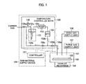
- Fig. 1 is a view showing the arrangement of a raw material supply device, and that of a thin film forming apparatus which receives a raw material supplied from the raw material supply device in an embodiment of the present invention
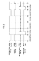
- Fig. 2 is a timing chart for explaining an example of the operation of the raw material supply device in the embodiment of the present invention.
- Fig. 1 is a view showing the arrangement of a raw material supply device, and that of a thin film forming apparatus which receives a raw material supplied from the raw material supply device in the embodiment of the present invention.
- the thin film forming apparatus includes a film forming chamber 101 in which a film is grown by epitaxial growth, a substrate table 102 which is arranged in the film forming chamber 101 and has a heating mechanism, and an exhaust mechanism 104.
- a raw material supply device 105 can supply a raw material to the thin film forming apparatus.
- a substrate 103 subjected to thin film formation is set on the substrate table 102.
- the thin film forming apparatus also includes an oxidizing gas supply unit 106 which supplies an oxidizing gas to the film forming chamber 101, and a purge gas supply unit 107 which supplies, to the film forming chamber 101, a purge gas consisting of an inert gas such as nitrogen gas or argon (Ar) gas.
- the thin film forming apparatus is, for example, an atomic layer deposition apparatus.
- the raw material supply device 105 includes a raw material vessel 151, introduction pipe 152a, transport pipe 152b, pump 153, and massflow controller (MFC) 154.
- the raw material vessel 151 contains a liquid raw material.
- the introduction pipe 152a is connected to the raw material vessel 151, and introduces a carrier gas into the raw material vessel 151.
- the transport pipe 152b is connected to the raw material vessel 151, and transports a source gas produced in the raw material vessel 151, together with the carrier gas.
- the pump 153 is attached to the transport pipe 152b, and transports the source gas and carrier gas.
- the MFC 154 controls the flow rates of the source gas and carrier gas transported by the pump 153.
- a carrier gas supply unit such as a cylinder containing the compressed carrier gas is connected to the introduction pipe 152a.
- the raw material supply device 105 also includes a supply pipe 155a, circulation pipe 155b, introduction valve 156a, supply valve 156b, circulation valve 156c, controller 157, and pressure gauge 158.
- the supply pipe 155a is branched from the transport pipe 152b, connected to the film forming chamber (supply target) 101, and supplies the source gas and carrier gas to the film forming chamber 101.
- the circulation pipe 155b is branched from the transport pipe 152b, connected to the introduction pipe 152a, and returns the source gas and carrier gas to the introduction pipe 152a (raw material vessel 151).
- the introduction valve 156a is attached to the introduction pipe 152a.
- the supply valve 156b is attached to the supply pipe 155a.
- the circulation valve 156c is attached to the circulation pipe 155b.
- the controller 157 is connected to the introduction valve 156a, supply valve 156b, and circulation valve 156c, and controls opening/closing of the valves 156a to 156c.
- the pressure gauge 158 is connected to the introduction pipe 152a.
- the introduction valve 156a is arranged on the carrier gas supply side from a portion of the introduction pipe 152a to which the circulation pipe 155b is connected. These portions are contained in a temperature controlled bath 159 and can be heated to (kept at) predetermined temperatures. Keeping predetermined temperatures can suppress liquefaction of a source gas in a pipe such as the circulation pipe 155b.
- an introduction pipe (bubble gas introduction port) communicating with the introduction pipe 152a is arranged deep in a raw material liquid contained in the raw material vessel 151, and can introduce a carrier gas into the raw material liquid (bubbling).
- the carrier gas is an inert gas such as nitrogen gas or Ar gas.
- the feed-out port of the transport pipe 152b is arranged in a space above the raw material liquid level in the raw material vessel 151 so as to be able to feed out the evaporated gas of the raw material liquid that is obtained by bubbling.
- the source gas and carrier gas whose flow rates are controlled by the MFC 154 after they are fed out from the raw material vessel 151 and transported by the pump 153 are guided to either the supply pipe 155a or circulation pipe 155b by opening/closing control of the supply valve 156b and circulation valve 156c by the controller 157.
- the supply valve 156b is opened and the circulation valve 156c is closed, the source gas and carrier gas flowing through the transport pipe 152b are guided to the supply pipe 155a and supplied to the film forming chamber 101.
- the circulation valve 156c is opened and the supply valve 156b is closed, the source gas and carrier gas flowing through the transport pipe 152b are guided to the circulation pipe 155b and returned to the introduction pipe 152a.
- the carrier gas is supplied to the introduction pipe 152a via the introduction valve 156a.
- the controller 157 controls opening/closing of the introduction valve 156a in accordance with the internal pressure value of the introduction pipe 152a that is measured by the pressure gauge 158. For example, the controller 157 holds set pressure values in advance. When a pressure value measured by the pressure gauge 158 becomes smaller than the lower limit of the set pressure value, the controller 157 controls to open the introduction valve 156a, introducing the carrier gas into the introduction pipe 152a. When a pressure value measured by the pressure gauge 158 becomes larger than the upper limit of the set pressure value, the controller 157 controls to close the introduction valve 156a, stopping the introduction of the carrier gas into the introduction pipe 152a.
- the carrier gas is supplied to the introduction pipe 152a, and introduced into the raw material liquid contained in the raw material vessel 151, bubbling the raw material liquid and producing its evaporated gas.
- the evaporated gas produced in the raw material vessel 151 is fed out from the raw material vessel 151 and transported through the transport pipe 152b by the pump 153.
- the MFC 154 controls the flow rate of the evaporated gas, and the evaporated gas returns to the introduction pipe 152a via the circulation pipe 155b.
- the controller 157 closes the introduction valve 156a, stopping the supply of the carrier gas to the introduction pipe 152a.
- the system of the introduction pipe 152a, raw material vessel 151, transport pipe 152b, and circulation pipe 155b shifts to a closed circulation state.
- the gas transportation by the pump 153 continues.
- the bubbling of the contained raw material liquid by the carrier gas from the bubble gas introduction port of the introduction pipe 152a continues. In this way, the source gas produced in the raw material vessel 151 circulates through the system together with the carrier gas.
- the controller 157 closes the circulation pipe 155b and opens the supply pipe 155a at time t1 when the adsorption step by the ALD method starts.
- the source gas and carrier gas whose flow rates are controlled by the MFC 154 after they are transported by the pump 153 are transported through the supply pipe 155a and introduced into the film forming chamber 101.
- the source gas introduced into the film forming chamber 101 is supplied onto the substrate 103 which is heated to a predetermined temperature by the substrate table 102.
- the source gas is adsorbed by the surface of the substrate 103, forming an adsorption layer corresponding to a one-molecular layer from the raw material on the surface of the substrate 103.
- the controller 157 controls to close the supply valve 156b and open the circulation valve 156c.
- the system shifts to the above-described circulation state in the raw material supply device 105.
- the bubbling of the contained raw material liquid by the carrier gas from the bubble gas introduction port of the introduction pipe 152a continues.
- the source gas produced in the raw material vessel 151 circulates through the system together with the carrier gas.
- the controller 157 opens the introduction valve 156a, introducing the carrier gas into the introduction pipe 152a. Also in this state, the bubbling of the contained raw material liquid by the carrier gas continues in the raw material vessel 151.
- the controller 157 closes the introduction valve 156a. In response to this, the supply of the carrier gas to the introduction pipe 152a stops, and the system shifts to the foregoing circulation state.
- the purge gas supply unit 107 introduces a purge gas such as nitrogen gas or Ar gas into the film forming chamber 101.
- the exhaust mechanism 104 exhausts the internal gas (source gas) from the film forming chamber 101.
- the circulation state continues till time t5 when a subsequence purge step ends and the next adsorption step starts after the oxidation state ends at time t4.
- the supply of the purge gas from the purge gas supply unit 107 stops, and the oxidizing gas supply unit 106 supplies an oxidizing gas.
- the adsorption layer corresponding to a one-molecular layer that is formed on the substrate 103 is oxidized, forming an oxide layer corresponding to a one-molecular layer.
- the purge gas supply unit 107 introduces the purge gas such as nitrogen gas or Ar gas into the film forming chamber 101.
- the exhaust mechanism 104 exhausts the internal gas (oxidizing gas) from the film forming chamber 101.
- the controller 157 closes the circulation pipe 155b and opens the supply pipe 155a in the above-described manner.
- the source gas and carrier gas whose flow rates are controlled by the MFC 154 after they are transported by the pump 153 are transported through the supply pipe 155a and introduced into the film forming chamber 101.
- the source gas introduced into the film forming chamber 101 is supplied onto the substrate 103, and adsorbed by the surface of the oxide layer formed on the substrate 103, forming an adsorption layer corresponding to a one-molecular layer from the raw material on the surface of the oxide layer.
- the controller 157 controls to close the supply valve 156b and open the circulation valve 156c.
- the purge gas supply unit 107 introduces the purge gas such as nitrogen gas or Ar gas into the film forming chamber 101.
- the exhaust mechanism 104 exhausts the internal gas (source gas) from the film forming chamber 101.
- the controller 157 controls to open the introduction valve 156a, introducing the carrier gas into the introduction pipe 152a.
- the controller 157 controls to close the introduction valve 156a. Accordingly, the supply of the carrier gas to the introduction pipe 152a stops, and the system shifts to the circulation state.
- the introduction valve 156a is opened to supply the carrier gas to the introduction pipe 152a at the end of the adsorption step, but the present invention is not limited to this.
- the controller 157 may control to open the introduction valve 156a and supply the carrier gas to the introduction pipe 152a.
- the controller 157 controls the supply valve 156b and circulation valve 156c to be in opposite open/closed states. Even when no source gas is supplied to the film forming chamber 101, the bubbling of the contained raw material liquid by the carrier gas continues in the raw material vessel 151, keeping producing the source gas. Further, the produced source gas is not wasted because it circulates from the introduction pipe 152a again to it via the circulation pipe 155b by the transportation operation of the pump 153.
Landscapes
- Chemical & Material Sciences (AREA)
- General Chemical & Material Sciences (AREA)
- Chemical Kinetics & Catalysis (AREA)
- Engineering & Computer Science (AREA)
- Materials Engineering (AREA)
- Metallurgy (AREA)
- Organic Chemistry (AREA)
- Mechanical Engineering (AREA)
- Crystallography & Structural Chemistry (AREA)
- Chemical Vapour Deposition (AREA)
Abstract
Description
- The present invention relates to a raw material supply device which supplies a source gas to a thin film forming apparatus for forming a thin film by epitaxial growth.
- Recently, ALD (Atomic Layer Deposition) capable of forming a thin film for each of atomic and molecular layers is receiving attention as a technique having various features including one capable of forming a high-quality thin film more uniformly at a temperature as low as about 300°C. The ALD method is an epitaxial growth technique of forming a thin film for each atomic layer by alternately supplying, to a substrate, the source gases of respective elements which constitute a film to be formed.
- In the formation of a thin film using the ALD method, for example, the gas of an organic compound of a metal which constitutes a film to be formed is used as a source gas. Most organic metal compounds are liquids at room temperature (about 20°C). Thus, an epitaxial growth technique such as ALD evaporates a liquid of an organic metal compound by so-called bubbling and uses it as a source gas (Japanese Patent Laid-Open Nos.
5-074758 5-251348 - The ALD method intermittently supplies a source gas onto a substrate. To implement the intermittent gas supply by bubbling, for example, there is a method of executing bubbling only when supplying gas. However, in the bubbling method, the gas producing state is unstable immediately after the start of bubbling. The amount (concentration) of produced evaporated gas after bubbling continues for some time changes from one immediately after bubbling starts. For the method of repeating the stop and start of bubbling, it is difficult to stably supply a source gas.
- In contrast, there is proposed a method of continuing bubbling, and while supplying no source gas, for example, switching the gas path to discard a produced source gas to an exhaust path. This method continues bubbling and thus can stably supply a source gas. However, since the source gas is discarded while the supply of the source gas to a substrate stops, the source gas is wasted, raising the raw material cost.
- The present invention has been made to solve the above problems and has as its object to allow supplying a source gas more stably while suppressing the waste of a raw material.
- A raw material supply device according to the present invention comprises a raw material vessel which contains a raw material liquid, an introduction pipe which is connected to the raw material vessel, and introduces a carrier gas into the raw material vessel to bubble the raw material liquid, a transport pipe which is connected to the raw material vessel, and transports a source gas that is produced by bubbling and fed out from the raw material vessel, a pump which is attached to the transport pipe and transports the source gas, a supply pipe which is branched from the transport pipe, connected to a supply target, and supplies the source gas to the supply target, a circulation pipe which is branched from the transport pipe and connected to the introduction pipe, an introduction valve which is arranged on a supply side of the carrier gas from a portion of the introduction pipe to which the circulation pipe is connected, a supply valve which is attached to the supply pipe, a circulation valve which is attached to the circulation pipe, and a controller which is connected to the introduction valve, the supply valve, and the circulation valve, and controls opening/closing of the valves, wherein the controller controls at least the supply valve and the circulation valve to be in opposite open/closed states.
- According to the present invention, a supply valve is attached to a supply pipe which is branched from a transport pipe and supplies a source gas to a supply target. A circulation valve is attached to a circulation pipe which is branched from the transport pipe and communicates with an introduction pipe. A controller controls at least the supply valve and circulation valve to be in opposite open/closed states. The source gas can be supplied more stably while suppressing the waste of the raw material.
-
Fig. 1 is a view showing the arrangement of a raw material supply device, and that of a thin film forming apparatus which receives a raw material supplied from the raw material supply device in an embodiment of the present invention; and
Fig. 2 is a timing chart for explaining an example of the operation of the raw material supply device in the embodiment of the present invention. - An embodiment of the present invention will be described with reference to the accompanying drawings.
Fig. 1 is a view showing the arrangement of a raw material supply device, and that of a thin film forming apparatus which receives a raw material supplied from the raw material supply device in the embodiment of the present invention. The thin film forming apparatus includes afilm forming chamber 101 in which a film is grown by epitaxial growth, a substrate table 102 which is arranged in thefilm forming chamber 101 and has a heating mechanism, and an exhaust mechanism 104. A rawmaterial supply device 105 can supply a raw material to the thin film forming apparatus. Asubstrate 103 subjected to thin film formation is set on the substrate table 102. The thin film forming apparatus also includes an oxidizinggas supply unit 106 which supplies an oxidizing gas to thefilm forming chamber 101, and a purgegas supply unit 107 which supplies, to thefilm forming chamber 101, a purge gas consisting of an inert gas such as nitrogen gas or argon (Ar) gas. The thin film forming apparatus is, for example, an atomic layer deposition apparatus. - The raw
material supply device 105 includes araw material vessel 151, introduction pipe 152a,transport pipe 152b,pump 153, and massflow controller (MFC) 154. Theraw material vessel 151 contains a liquid raw material. The introduction pipe 152a is connected to theraw material vessel 151, and introduces a carrier gas into theraw material vessel 151. Thetransport pipe 152b is connected to theraw material vessel 151, and transports a source gas produced in theraw material vessel 151, together with the carrier gas. Thepump 153 is attached to thetransport pipe 152b, and transports the source gas and carrier gas. The MFC 154 controls the flow rates of the source gas and carrier gas transported by thepump 153. Although not shown, a carrier gas supply unit such as a cylinder containing the compressed carrier gas is connected to the introduction pipe 152a. - The raw
material supply device 105 also includes a supply pipe 155a,circulation pipe 155b, introduction valve 156a, supply valve 156b,circulation valve 156c,controller 157, andpressure gauge 158. The supply pipe 155a is branched from thetransport pipe 152b, connected to the film forming chamber (supply target) 101, and supplies the source gas and carrier gas to thefilm forming chamber 101. Thecirculation pipe 155b is branched from thetransport pipe 152b, connected to the introduction pipe 152a, and returns the source gas and carrier gas to the introduction pipe 152a (raw material vessel 151). The introduction valve 156a is attached to the introduction pipe 152a. The supply valve 156b is attached to the supply pipe 155a. Thecirculation valve 156c is attached to thecirculation pipe 155b. Thecontroller 157 is connected to the introduction valve 156a, supply valve 156b, andcirculation valve 156c, and controls opening/closing of the valves 156a to 156c. Thepressure gauge 158 is connected to the introduction pipe 152a. The introduction valve 156a is arranged on the carrier gas supply side from a portion of the introduction pipe 152a to which thecirculation pipe 155b is connected. These portions are contained in a temperature controlledbath 159 and can be heated to (kept at) predetermined temperatures. Keeping predetermined temperatures can suppress liquefaction of a source gas in a pipe such as thecirculation pipe 155b. - In the
raw material vessel 151, an introduction pipe (bubble gas introduction port) communicating with the introduction pipe 152a is arranged deep in a raw material liquid contained in theraw material vessel 151, and can introduce a carrier gas into the raw material liquid (bubbling). The carrier gas is an inert gas such as nitrogen gas or Ar gas. The feed-out port of thetransport pipe 152b is arranged in a space above the raw material liquid level in theraw material vessel 151 so as to be able to feed out the evaporated gas of the raw material liquid that is obtained by bubbling. - The source gas and carrier gas whose flow rates are controlled by the
MFC 154 after they are fed out from theraw material vessel 151 and transported by thepump 153 are guided to either the supply pipe 155a orcirculation pipe 155b by opening/closing control of the supply valve 156b andcirculation valve 156c by thecontroller 157. For example, when the supply valve 156b is opened and thecirculation valve 156c is closed, the source gas and carrier gas flowing through thetransport pipe 152b are guided to the supply pipe 155a and supplied to thefilm forming chamber 101. When thecirculation valve 156c is opened and the supply valve 156b is closed, the source gas and carrier gas flowing through thetransport pipe 152b are guided to thecirculation pipe 155b and returned to the introduction pipe 152a. - The carrier gas is supplied to the introduction pipe 152a via the introduction valve 156a. The
controller 157 controls opening/closing of the introduction valve 156a in accordance with the internal pressure value of the introduction pipe 152a that is measured by thepressure gauge 158. For example, thecontroller 157 holds set pressure values in advance. When a pressure value measured by thepressure gauge 158 becomes smaller than the lower limit of the set pressure value, thecontroller 157 controls to open the introduction valve 156a, introducing the carrier gas into the introduction pipe 152a. When a pressure value measured by thepressure gauge 158 becomes larger than the upper limit of the set pressure value, thecontroller 157 controls to close the introduction valve 156a, stopping the introduction of the carrier gas into the introduction pipe 152a. - An example of control of each valve by the
controller 157 and an example of a source gas supply operation will be explained with reference to the arrangement view ofFig. 1 and the timing chart ofFig. 2 . In the initial stage, the internal pressure of the introduction pipe 152a has not reached the upper limit of the set pressure value, and thin film formation in the thin film forming apparatus has not started. In this state, thecontroller 157 controls to close the supply valve 156b and open the introduction valve 156a andcirculation valve 156c. Thepump 153 transports a gas in thetransport pipe 152b from theraw material vessel 151 to theMFC 154. - Accordingly, the carrier gas is supplied to the introduction pipe 152a, and introduced into the raw material liquid contained in the
raw material vessel 151, bubbling the raw material liquid and producing its evaporated gas. The evaporated gas produced in theraw material vessel 151 is fed out from theraw material vessel 151 and transported through thetransport pipe 152b by thepump 153. TheMFC 154 controls the flow rate of the evaporated gas, and the evaporated gas returns to the introduction pipe 152a via thecirculation pipe 155b. - After that, the internal pressure of the introduction pipe 152a reaches the upper limit of the set pressure value, and the
pressure gauge 158 detects it. Then, thecontroller 157 closes the introduction valve 156a, stopping the supply of the carrier gas to the introduction pipe 152a. As a result, the system of the introduction pipe 152a,raw material vessel 151,transport pipe 152b, andcirculation pipe 155b shifts to a closed circulation state. In the closed system, the gas transportation by thepump 153 continues. In theraw material vessel 151, the bubbling of the contained raw material liquid by the carrier gas from the bubble gas introduction port of the introduction pipe 152a continues. In this way, the source gas produced in theraw material vessel 151 circulates through the system together with the carrier gas. - As described above, after the system shifts to the circulation state, the
controller 157 closes thecirculation pipe 155b and opens the supply pipe 155a at time t1 when the adsorption step by the ALD method starts. Under this control, the source gas and carrier gas whose flow rates are controlled by theMFC 154 after they are transported by thepump 153 are transported through the supply pipe 155a and introduced into thefilm forming chamber 101. The source gas introduced into thefilm forming chamber 101 is supplied onto thesubstrate 103 which is heated to a predetermined temperature by the substrate table 102. The source gas is adsorbed by the surface of thesubstrate 103, forming an adsorption layer corresponding to a one-molecular layer from the raw material on the surface of thesubstrate 103. - At time t2 when the adsorption step ends and the purge step starts, the
controller 157 controls to close the supply valve 156b and open thecirculation valve 156c. As a result, the system shifts to the above-described circulation state in the rawmaterial supply device 105. In theraw material vessel 151, the bubbling of the contained raw material liquid by the carrier gas from the bubble gas introduction port of the introduction pipe 152a continues. The source gas produced in theraw material vessel 151 circulates through the system together with the carrier gas. - At this time, for example, if the internal pressure of the introduction pipe 152a decreases to be equal to or lower than the lower limit of the set pressure value owing to the supply of the source gas to the
film forming chamber 101 and thepressure gauge 158 detects it, thecontroller 157 opens the introduction valve 156a, introducing the carrier gas into the introduction pipe 152a. Also in this state, the bubbling of the contained raw material liquid by the carrier gas continues in theraw material vessel 151.
At time t2' during the purge step, if the internal pressure of the introduction pipe 152a reaches the upper limit of the set pressure value and thepressure gauge 158 detects it, thecontroller 157 closes the introduction valve 156a. In response to this, the supply of the carrier gas to the introduction pipe 152a stops, and the system shifts to the foregoing circulation state. - In the purge step, the purge
gas supply unit 107 introduces a purge gas such as nitrogen gas or Ar gas into thefilm forming chamber 101. In addition, the exhaust mechanism 104 exhausts the internal gas (source gas) from thefilm forming chamber 101. - When the purge step ends and the oxidation step starts at time t3, the circulation state continues till time t5 when a subsequence purge step ends and the next adsorption step starts after the oxidation state ends at time t4. In the oxidation step, the supply of the purge gas from the purge
gas supply unit 107 stops, and the oxidizinggas supply unit 106 supplies an oxidizing gas. By supplying the oxidizing gas, the adsorption layer corresponding to a one-molecular layer that is formed on thesubstrate 103 is oxidized, forming an oxide layer corresponding to a one-molecular layer. In the purge step which starts at time t4, the purgegas supply unit 107 introduces the purge gas such as nitrogen gas or Ar gas into thefilm forming chamber 101. In addition, the exhaust mechanism 104 exhausts the internal gas (oxidizing gas) from thefilm forming chamber 101. - When the purge step ends and the next adsorption step starts at time t5, the
controller 157 closes thecirculation pipe 155b and opens the supply pipe 155a in the above-described manner. Under this control, the source gas and carrier gas whose flow rates are controlled by theMFC 154 after they are transported by thepump 153 are transported through the supply pipe 155a and introduced into thefilm forming chamber 101. The source gas introduced into thefilm forming chamber 101 is supplied onto thesubstrate 103, and adsorbed by the surface of the oxide layer formed on thesubstrate 103, forming an adsorption layer corresponding to a one-molecular layer from the raw material on the surface of the oxide layer. - At time t6 when the adsorption step ends and the purge step starts, the
controller 157 controls to close the supply valve 156b and open thecirculation valve 156c. In this purge step, the purgegas supply unit 107 introduces the purge gas such as nitrogen gas or Ar gas into thefilm forming chamber 101. In addition, the exhaust mechanism 104 exhausts the internal gas (source gas) from thefilm forming chamber 101. - At this time, as described above, if the internal pressure of the introduction pipe 152a decreases to be equal to or lower than the lower limit of the set pressure value owing to the supply of the source gas to the
film forming chamber 101 and thepressure gauge 158 detects it, thecontroller 157 controls to open the introduction valve 156a, introducing the carrier gas into the introduction pipe 152a. At time t6' during the purge step, if the internal pressure of the introduction pipe 152a reaches the upper limit of the set pressure value and thepressure gauge 158 detects it, thecontroller 157 controls to close the introduction valve 156a. Accordingly, the supply of the carrier gas to the introduction pipe 152a stops, and the system shifts to the circulation state. - This well-known ALD cycle of adsorption, purge, oxidation, and purge is repeated, forming, on the
substrate 103, a desired thin film made of, for example, the oxide of a metal that constitutes the raw material. In the above description, the introduction valve 156a is opened to supply the carrier gas to the introduction pipe 152a at the end of the adsorption step, but the present invention is not limited to this. For example, if thepressure gauge 158 detects that the internal pressure of the introduction pipe 152a decreases to be lower than the lower limit of the set pressure value while supplying the source gas to thefilm forming chamber 101 in the adsorption step, thecontroller 157 may control to open the introduction valve 156a and supply the carrier gas to the introduction pipe 152a. - As described above, according to the embodiment, the
controller 157 controls the supply valve 156b andcirculation valve 156c to be in opposite open/closed states. Even when no source gas is supplied to thefilm forming chamber 101, the bubbling of the contained raw material liquid by the carrier gas continues in theraw material vessel 151, keeping producing the source gas. Further, the produced source gas is not wasted because it circulates from the introduction pipe 152a again to it via thecirculation pipe 155b by the transportation operation of thepump 153.
Claims (2)
- A raw material supply device comprising:a raw material vessel which contains a raw material liquid;an introduction pipe which is connected to said raw material vessel, and introduces a carrier gas into said raw material vessel to bubble the raw material liquid;a transport pipe which is connected to said raw material vessel, and transports a source gas that is produced by bubbling and fed out from said raw material vessel;a pump which is attached to said transport pipe and transports the source gas;a supply pipe which is branched from said transport pipe, connected to a supply target, and supplies the source gas to the supply target;a circulation pipe which is branched from said transport pipe and connected to said introduction pipe;an introduction valve which is arranged on a supply side of the carrier gas from a portion of said introduction pipe to which said circulation pipe is connected;a supply valve which is attached to said supply pipe;a circulation valve which is attached to said circulation pipe; anda controller which is connected to said introduction valve, said supply valve, and said circulation valve, and controls opening/closing of said valves,wherein said controller controls at least said supply valve and said circulation valve to be in opposite open/closed states.
- A raw material supply device according to claim 1, further comprising a pressure gauge which measures an internal pressure of said introduction pipe between said introduction valve and said raw material vessel,
wherein said controller controls to open/close said introduction valve in accordance with a measurement result of said pressure gauge.
Applications Claiming Priority (2)
| Application Number | Priority Date | Filing Date | Title |
|---|---|---|---|
| JP2008063076A JP4418001B2 (en) | 2008-03-12 | 2008-03-12 | Raw material supply equipment |
| PCT/JP2009/053543 WO2009113400A1 (en) | 2008-03-12 | 2009-02-26 | Raw material supplying device |
Publications (3)
| Publication Number | Publication Date |
|---|---|
| EP2251451A1 true EP2251451A1 (en) | 2010-11-17 |
| EP2251451A4 EP2251451A4 (en) | 2014-12-24 |
| EP2251451B1 EP2251451B1 (en) | 2016-01-27 |
Family
ID=41065069
Family Applications (1)
| Application Number | Title | Priority Date | Filing Date |
|---|---|---|---|
| EP09720876.3A Not-in-force EP2251451B1 (en) | 2008-03-12 | 2009-02-26 | Raw material supplying device |
Country Status (6)
| Country | Link |
|---|---|
| US (1) | US8382071B2 (en) |
| EP (1) | EP2251451B1 (en) |
| JP (1) | JP4418001B2 (en) |
| KR (1) | KR101246921B1 (en) |
| TW (1) | TW200947507A (en) |
| WO (1) | WO2009113400A1 (en) |
Families Citing this family (8)
| Publication number | Priority date | Publication date | Assignee | Title |
|---|---|---|---|---|
| US10443127B2 (en) | 2013-11-05 | 2019-10-15 | Taiwan Semiconductor Manufacturing Company Limited | System and method for supplying a precursor for an atomic layer deposition (ALD) process |
| JP2015190035A (en) * | 2014-03-28 | 2015-11-02 | 東京エレクトロン株式会社 | Gas supply mechanism and gas supply method, and film forming apparatus and film forming method using the same |
| US11970772B2 (en) | 2014-08-22 | 2024-04-30 | Lam Research Corporation | Dynamic precursor dosing for atomic layer deposition |
| US10094018B2 (en) | 2014-10-16 | 2018-10-09 | Lam Research Corporation | Dynamic precursor dosing for atomic layer deposition |
| US11072860B2 (en) | 2014-08-22 | 2021-07-27 | Lam Research Corporation | Fill on demand ampoule refill |
| JP7089902B2 (en) * | 2018-02-28 | 2022-06-23 | 株式会社Screenホールディングス | Substrate processing equipment, processing liquid discharge method in the substrate processing equipment, processing liquid exchange method in the substrate processing equipment, substrate processing method in the substrate processing equipment |
| JP7508428B2 (en) * | 2021-09-22 | 2024-07-01 | 株式会社東芝 | Semiconductor Manufacturing Equipment |
| CN115585397B (en) * | 2022-09-29 | 2025-11-21 | 拓荆科技股份有限公司 | Gas transmission pipeline system |
Family Cites Families (14)
| Publication number | Priority date | Publication date | Assignee | Title |
|---|---|---|---|---|
| GB1269202A (en) * | 1968-02-14 | 1972-04-06 | Fordath Ltd | Improvements in the production of cores for use in the production of metal castings |
| JPH0574758A (en) | 1991-09-17 | 1993-03-26 | Mitsubishi Electric Corp | Chemical vapor deposition apparatus |
| JPH05251348A (en) | 1992-03-05 | 1993-09-28 | Mitsubishi Electric Corp | Bubbler and gas supply |
| JPH10130845A (en) | 1996-10-29 | 1998-05-19 | Mitsubishi Heavy Ind Ltd | Vapor generating device for chemical vapor deposition |
| TW565626B (en) * | 1996-11-20 | 2003-12-11 | Ebara Corp | Liquid feed vaporization system and gas injection device |
| US6089184A (en) * | 1997-06-11 | 2000-07-18 | Tokyo Electron Limited | CVD apparatus and CVD method |
| US5972117A (en) * | 1997-09-03 | 1999-10-26 | Applied Materials, Inc. | Method and apparatus for monitoring generation of liquid chemical vapor |
| JP3706294B2 (en) | 2000-03-27 | 2005-10-12 | 東京エレクトロン株式会社 | Treatment liquid supply apparatus and treatment liquid supply method |
| JP4652860B2 (en) | 2004-04-27 | 2011-03-16 | 大陽日酸株式会社 | How to recover krypton or xenon |
| JP5264039B2 (en) * | 2004-08-10 | 2013-08-14 | 東京エレクトロン株式会社 | Thin film forming apparatus and thin film forming method |
| US7562672B2 (en) * | 2006-03-30 | 2009-07-21 | Applied Materials, Inc. | Chemical delivery apparatus for CVD or ALD |
| WO2007114156A1 (en) | 2006-03-30 | 2007-10-11 | Mitsui Engineering & Shipbuilding Co., Ltd. | Atomic layer growing apparatus |
| US8016945B2 (en) * | 2007-12-21 | 2011-09-13 | Applied Materials, Inc. | Hafnium oxide ALD process |
| WO2010056576A1 (en) * | 2008-11-11 | 2010-05-20 | Praxair Technology, Inc. | Reagent dispensing apparatuses and delivery methods |
-
2008
- 2008-03-12 JP JP2008063076A patent/JP4418001B2/en active Active
-
2009
- 2009-02-26 KR KR1020107018621A patent/KR101246921B1/en active Active
- 2009-02-26 US US12/921,771 patent/US8382071B2/en not_active Expired - Fee Related
- 2009-02-26 WO PCT/JP2009/053543 patent/WO2009113400A1/en not_active Ceased
- 2009-02-26 EP EP09720876.3A patent/EP2251451B1/en not_active Not-in-force
- 2009-03-06 TW TW98107318A patent/TW200947507A/en unknown
Also Published As
| Publication number | Publication date |
|---|---|
| TW200947507A (en) | 2009-11-16 |
| JP4418001B2 (en) | 2010-02-17 |
| KR101246921B1 (en) | 2013-03-25 |
| WO2009113400A1 (en) | 2009-09-17 |
| US20110000554A1 (en) | 2011-01-06 |
| KR20100109559A (en) | 2010-10-08 |
| EP2251451A4 (en) | 2014-12-24 |
| JP2009215635A (en) | 2009-09-24 |
| US8382071B2 (en) | 2013-02-26 |
| EP2251451B1 (en) | 2016-01-27 |
Similar Documents
| Publication | Publication Date | Title |
|---|---|---|
| EP2251451B1 (en) | Raw material supplying device | |
| KR101161020B1 (en) | Atomic layer growing apparatus | |
| KR20120126012A (en) | Gas supply apparatus, thermal treatment apparatus, gas supply method, and thermal treatment method | |
| JP2021118355A (en) | System for stabilizing reaction chamber pressure and method | |
| US11560624B2 (en) | Precursor delivery system | |
| US8518181B2 (en) | Film forming apparatus and film forming method | |
| CN109666921B (en) | Systems and methods for atomic layer deposition | |
| US20100266765A1 (en) | Method and apparatus for growing a thin film onto a substrate | |
| JP5616591B2 (en) | Semiconductor device manufacturing method and substrate processing apparatus | |
| US9466477B2 (en) | Method of manufacturing semiconductor device, substrate processing apparatus, and semiconductor device | |
| TWI300097B (en) | Source gas delivery | |
| JP2014007289A (en) | Gas supply device and film forming device | |
| JP2015190035A (en) | Gas supply mechanism and gas supply method, and film forming apparatus and film forming method using the same | |
| JP2017085088A (en) | Dynamic precursor dosing for atomic layer deposition | |
| JP2013076113A (en) | Gas supply device and film deposition apparatus | |
| JP2009016799A (en) | Substrate processing equipment | |
| JP2018041898A (en) | Film forming method and film forming system | |
| JP2005307233A (en) | Film forming apparatus, film forming method, and process gas supply method | |
| JPWO2005024926A1 (en) | Substrate processing apparatus and semiconductor device manufacturing method | |
| EP4056731A1 (en) | Film formation method and film formation device | |
| US20060019029A1 (en) | Atomic layer deposition methods and apparatus | |
| JP2006222265A (en) | Substrate processing equipment | |
| JPS63136614A (en) | processing equipment | |
| JP2006066557A (en) | Substrate processing equipment | |
| JP2611008B2 (en) | Organic metal compound vaporizer |
Legal Events
| Date | Code | Title | Description |
|---|---|---|---|
| PUAI | Public reference made under article 153(3) epc to a published international application that has entered the european phase |
Free format text: ORIGINAL CODE: 0009012 |
|
| 17P | Request for examination filed |
Effective date: 20100901 |
|
| AK | Designated contracting states |
Kind code of ref document: A1 Designated state(s): AT BE BG CH CY CZ DE DK EE ES FI FR GB GR HR HU IE IS IT LI LT LU LV MC MK MT NL NO PL PT RO SE SI SK TR |
|
| AX | Request for extension of the european patent |
Extension state: AL BA RS |
|
| DAX | Request for extension of the european patent (deleted) | ||
| A4 | Supplementary search report drawn up and despatched |
Effective date: 20141120 |
|
| RIC1 | Information provided on ipc code assigned before grant |
Ipc: C30B 25/14 20060101ALI20141114BHEP Ipc: H01L 21/31 20060101ALI20141114BHEP Ipc: C23C 16/448 20060101AFI20141114BHEP Ipc: C23C 16/455 20060101ALI20141114BHEP |
|
| GRAP | Despatch of communication of intention to grant a patent |
Free format text: ORIGINAL CODE: EPIDOSNIGR1 |
|
| RIC1 | Information provided on ipc code assigned before grant |
Ipc: C30B 25/14 20060101ALI20150701BHEP Ipc: H01L 21/31 20060101ALI20150701BHEP Ipc: C23C 16/448 20060101AFI20150701BHEP Ipc: C23C 16/455 20060101ALI20150701BHEP |
|
| INTG | Intention to grant announced |
Effective date: 20150722 |
|
| GRAS | Grant fee paid |
Free format text: ORIGINAL CODE: EPIDOSNIGR3 |
|
| GRAA | (expected) grant |
Free format text: ORIGINAL CODE: 0009210 |
|
| AK | Designated contracting states |
Kind code of ref document: B1 Designated state(s): AT BE BG CH CY CZ DE DK EE ES FI FR GB GR HR HU IE IS IT LI LT LU LV MC MK MT NL NO PL PT RO SE SI SK TR |
|
| REG | Reference to a national code |
Ref country code: GB Ref legal event code: FG4D |
|
| REG | Reference to a national code |
Ref country code: CH Ref legal event code: EP |
|
| REG | Reference to a national code |
Ref country code: AT Ref legal event code: REF Ref document number: 772763 Country of ref document: AT Kind code of ref document: T Effective date: 20160215 |
|
| REG | Reference to a national code |
Ref country code: IE Ref legal event code: FG4D |
|
| REG | Reference to a national code |
Ref country code: FR Ref legal event code: PLFP Year of fee payment: 8 |
|
| REG | Reference to a national code |
Ref country code: DE Ref legal event code: R096 Ref document number: 602009035987 Country of ref document: DE |
|
| REG | Reference to a national code |
Ref country code: LT Ref legal event code: MG4D |
|
| PG25 | Lapsed in a contracting state [announced via postgrant information from national office to epo] |
Ref country code: BE Free format text: LAPSE BECAUSE OF NON-PAYMENT OF DUE FEES Effective date: 20160229 |
|
| REG | Reference to a national code |
Ref country code: NL Ref legal event code: MP Effective date: 20160127 |
|
| REG | Reference to a national code |
Ref country code: AT Ref legal event code: MK05 Ref document number: 772763 Country of ref document: AT Kind code of ref document: T Effective date: 20160127 |
|
| PG25 | Lapsed in a contracting state [announced via postgrant information from national office to epo] |
Ref country code: NL Free format text: LAPSE BECAUSE OF FAILURE TO SUBMIT A TRANSLATION OF THE DESCRIPTION OR TO PAY THE FEE WITHIN THE PRESCRIBED TIME-LIMIT Effective date: 20160127 |
|
| PG25 | Lapsed in a contracting state [announced via postgrant information from national office to epo] |
Ref country code: GR Free format text: LAPSE BECAUSE OF FAILURE TO SUBMIT A TRANSLATION OF THE DESCRIPTION OR TO PAY THE FEE WITHIN THE PRESCRIBED TIME-LIMIT Effective date: 20160428 Ref country code: FI Free format text: LAPSE BECAUSE OF FAILURE TO SUBMIT A TRANSLATION OF THE DESCRIPTION OR TO PAY THE FEE WITHIN THE PRESCRIBED TIME-LIMIT Effective date: 20160127 Ref country code: ES Free format text: LAPSE BECAUSE OF FAILURE TO SUBMIT A TRANSLATION OF THE DESCRIPTION OR TO PAY THE FEE WITHIN THE PRESCRIBED TIME-LIMIT Effective date: 20160127 Ref country code: NO Free format text: LAPSE BECAUSE OF FAILURE TO SUBMIT A TRANSLATION OF THE DESCRIPTION OR TO PAY THE FEE WITHIN THE PRESCRIBED TIME-LIMIT Effective date: 20160427 Ref country code: HR Free format text: LAPSE BECAUSE OF FAILURE TO SUBMIT A TRANSLATION OF THE DESCRIPTION OR TO PAY THE FEE WITHIN THE PRESCRIBED TIME-LIMIT Effective date: 20160127 Ref country code: IT Free format text: LAPSE BECAUSE OF FAILURE TO SUBMIT A TRANSLATION OF THE DESCRIPTION OR TO PAY THE FEE WITHIN THE PRESCRIBED TIME-LIMIT Effective date: 20160127 |
|
| PG25 | Lapsed in a contracting state [announced via postgrant information from national office to epo] |
Ref country code: LV Free format text: LAPSE BECAUSE OF FAILURE TO SUBMIT A TRANSLATION OF THE DESCRIPTION OR TO PAY THE FEE WITHIN THE PRESCRIBED TIME-LIMIT Effective date: 20160127 Ref country code: IS Free format text: LAPSE BECAUSE OF FAILURE TO SUBMIT A TRANSLATION OF THE DESCRIPTION OR TO PAY THE FEE WITHIN THE PRESCRIBED TIME-LIMIT Effective date: 20160527 Ref country code: AT Free format text: LAPSE BECAUSE OF FAILURE TO SUBMIT A TRANSLATION OF THE DESCRIPTION OR TO PAY THE FEE WITHIN THE PRESCRIBED TIME-LIMIT Effective date: 20160127 Ref country code: PL Free format text: LAPSE BECAUSE OF FAILURE TO SUBMIT A TRANSLATION OF THE DESCRIPTION OR TO PAY THE FEE WITHIN THE PRESCRIBED TIME-LIMIT Effective date: 20160127 Ref country code: SE Free format text: LAPSE BECAUSE OF FAILURE TO SUBMIT A TRANSLATION OF THE DESCRIPTION OR TO PAY THE FEE WITHIN THE PRESCRIBED TIME-LIMIT Effective date: 20160127 Ref country code: PT Free format text: LAPSE BECAUSE OF FAILURE TO SUBMIT A TRANSLATION OF THE DESCRIPTION OR TO PAY THE FEE WITHIN THE PRESCRIBED TIME-LIMIT Effective date: 20160527 Ref country code: LT Free format text: LAPSE BECAUSE OF FAILURE TO SUBMIT A TRANSLATION OF THE DESCRIPTION OR TO PAY THE FEE WITHIN THE PRESCRIBED TIME-LIMIT Effective date: 20160127 |
|
| REG | Reference to a national code |
Ref country code: CH Ref legal event code: PL |
|
| REG | Reference to a national code |
Ref country code: DE Ref legal event code: R097 Ref document number: 602009035987 Country of ref document: DE |
|
| PG25 | Lapsed in a contracting state [announced via postgrant information from national office to epo] |
Ref country code: MC Free format text: LAPSE BECAUSE OF FAILURE TO SUBMIT A TRANSLATION OF THE DESCRIPTION OR TO PAY THE FEE WITHIN THE PRESCRIBED TIME-LIMIT Effective date: 20160127 Ref country code: DK Free format text: LAPSE BECAUSE OF FAILURE TO SUBMIT A TRANSLATION OF THE DESCRIPTION OR TO PAY THE FEE WITHIN THE PRESCRIBED TIME-LIMIT Effective date: 20160127 Ref country code: CH Free format text: LAPSE BECAUSE OF NON-PAYMENT OF DUE FEES Effective date: 20160229 Ref country code: LI Free format text: LAPSE BECAUSE OF NON-PAYMENT OF DUE FEES Effective date: 20160229 Ref country code: EE Free format text: LAPSE BECAUSE OF FAILURE TO SUBMIT A TRANSLATION OF THE DESCRIPTION OR TO PAY THE FEE WITHIN THE PRESCRIBED TIME-LIMIT Effective date: 20160127 |
|
| PG25 | Lapsed in a contracting state [announced via postgrant information from national office to epo] |
Ref country code: CZ Free format text: LAPSE BECAUSE OF FAILURE TO SUBMIT A TRANSLATION OF THE DESCRIPTION OR TO PAY THE FEE WITHIN THE PRESCRIBED TIME-LIMIT Effective date: 20160127 Ref country code: RO Free format text: LAPSE BECAUSE OF FAILURE TO SUBMIT A TRANSLATION OF THE DESCRIPTION OR TO PAY THE FEE WITHIN THE PRESCRIBED TIME-LIMIT Effective date: 20160127 Ref country code: SK Free format text: LAPSE BECAUSE OF FAILURE TO SUBMIT A TRANSLATION OF THE DESCRIPTION OR TO PAY THE FEE WITHIN THE PRESCRIBED TIME-LIMIT Effective date: 20160127 |
|
| REG | Reference to a national code |
Ref country code: IE Ref legal event code: MM4A |
|
| PLBE | No opposition filed within time limit |
Free format text: ORIGINAL CODE: 0009261 |
|
| STAA | Information on the status of an ep patent application or granted ep patent |
Free format text: STATUS: NO OPPOSITION FILED WITHIN TIME LIMIT |
|
| PG25 | Lapsed in a contracting state [announced via postgrant information from national office to epo] |
Ref country code: BE Free format text: LAPSE BECAUSE OF FAILURE TO SUBMIT A TRANSLATION OF THE DESCRIPTION OR TO PAY THE FEE WITHIN THE PRESCRIBED TIME-LIMIT Effective date: 20160127 |
|
| 26N | No opposition filed |
Effective date: 20161028 |
|
| PG25 | Lapsed in a contracting state [announced via postgrant information from national office to epo] |
Ref country code: IE Free format text: LAPSE BECAUSE OF NON-PAYMENT OF DUE FEES Effective date: 20160226 |
|
| PG25 | Lapsed in a contracting state [announced via postgrant information from national office to epo] |
Ref country code: BG Free format text: LAPSE BECAUSE OF FAILURE TO SUBMIT A TRANSLATION OF THE DESCRIPTION OR TO PAY THE FEE WITHIN THE PRESCRIBED TIME-LIMIT Effective date: 20160427 Ref country code: SI Free format text: LAPSE BECAUSE OF FAILURE TO SUBMIT A TRANSLATION OF THE DESCRIPTION OR TO PAY THE FEE WITHIN THE PRESCRIBED TIME-LIMIT Effective date: 20160127 |
|
| REG | Reference to a national code |
Ref country code: FR Ref legal event code: PLFP Year of fee payment: 9 |
|
| PG25 | Lapsed in a contracting state [announced via postgrant information from national office to epo] |
Ref country code: MT Free format text: LAPSE BECAUSE OF FAILURE TO SUBMIT A TRANSLATION OF THE DESCRIPTION OR TO PAY THE FEE WITHIN THE PRESCRIBED TIME-LIMIT Effective date: 20160127 |
|
| REG | Reference to a national code |
Ref country code: FR Ref legal event code: PLFP Year of fee payment: 10 |
|
| PG25 | Lapsed in a contracting state [announced via postgrant information from national office to epo] |
Ref country code: HU Free format text: LAPSE BECAUSE OF FAILURE TO SUBMIT A TRANSLATION OF THE DESCRIPTION OR TO PAY THE FEE WITHIN THE PRESCRIBED TIME-LIMIT; INVALID AB INITIO Effective date: 20090226 Ref country code: CY Free format text: LAPSE BECAUSE OF FAILURE TO SUBMIT A TRANSLATION OF THE DESCRIPTION OR TO PAY THE FEE WITHIN THE PRESCRIBED TIME-LIMIT Effective date: 20160127 |
|
| PG25 | Lapsed in a contracting state [announced via postgrant information from national office to epo] |
Ref country code: LU Free format text: LAPSE BECAUSE OF NON-PAYMENT OF DUE FEES Effective date: 20160226 Ref country code: TR Free format text: LAPSE BECAUSE OF FAILURE TO SUBMIT A TRANSLATION OF THE DESCRIPTION OR TO PAY THE FEE WITHIN THE PRESCRIBED TIME-LIMIT Effective date: 20160127 Ref country code: MK Free format text: LAPSE BECAUSE OF FAILURE TO SUBMIT A TRANSLATION OF THE DESCRIPTION OR TO PAY THE FEE WITHIN THE PRESCRIBED TIME-LIMIT Effective date: 20160127 Ref country code: MT Free format text: LAPSE BECAUSE OF FAILURE TO SUBMIT A TRANSLATION OF THE DESCRIPTION OR TO PAY THE FEE WITHIN THE PRESCRIBED TIME-LIMIT Effective date: 20160229 |
|
| REG | Reference to a national code |
Ref country code: GB Ref legal event code: 732E Free format text: REGISTERED BETWEEN 20180628 AND 20180706 |
|
| REG | Reference to a national code |
Ref country code: DE Ref legal event code: R082 Ref document number: 602009035987 Country of ref document: DE Representative=s name: LS-MP VON PUTTKAMER BERNGRUBER LOTH SPUHLER MU, DE Ref country code: DE Ref legal event code: R081 Ref document number: 602009035987 Country of ref document: DE Owner name: MITSUI E&S MACHINERY CO., LTD., JP Free format text: FORMER OWNER: MITSUI ENGINEERING & SHIPBUILDING CO., LTD., TOKIO, JP |
|
| PGFP | Annual fee paid to national office [announced via postgrant information from national office to epo] |
Ref country code: DE Payment date: 20240220 Year of fee payment: 16 Ref country code: GB Payment date: 20240226 Year of fee payment: 16 |
|
| REG | Reference to a national code |
Ref country code: GB Ref legal event code: 732E Free format text: REGISTERED BETWEEN 20240418 AND 20240424 |
|
| PGFP | Annual fee paid to national office [announced via postgrant information from national office to epo] |
Ref country code: FR Payment date: 20240104 Year of fee payment: 16 |
|
| REG | Reference to a national code |
Ref country code: DE Ref legal event code: R119 Ref document number: 602009035987 Country of ref document: DE |
|
| GBPC | Gb: european patent ceased through non-payment of renewal fee |
Effective date: 20250226 |
|
| PG25 | Lapsed in a contracting state [announced via postgrant information from national office to epo] |
Ref country code: DE Free format text: LAPSE BECAUSE OF NON-PAYMENT OF DUE FEES Effective date: 20250902 |
|
| PG25 | Lapsed in a contracting state [announced via postgrant information from national office to epo] |
Ref country code: GB Free format text: LAPSE BECAUSE OF NON-PAYMENT OF DUE FEES Effective date: 20250226 |
|
| PG25 | Lapsed in a contracting state [announced via postgrant information from national office to epo] |
Ref country code: FR Free format text: LAPSE BECAUSE OF NON-PAYMENT OF DUE FEES Effective date: 20250228 |