EP2251277B1 - Container for underground installation and method of transporting the same - Google Patents
Container for underground installation and method of transporting the same Download PDFInfo
- Publication number
- EP2251277B1 EP2251277B1 EP10175413.3A EP10175413A EP2251277B1 EP 2251277 B1 EP2251277 B1 EP 2251277B1 EP 10175413 A EP10175413 A EP 10175413A EP 2251277 B1 EP2251277 B1 EP 2251277B1
- Authority
- EP
- European Patent Office
- Prior art keywords
- container
- transport
- mounts
- ascending tube
- tube
- Prior art date
- Legal status (The legal status is an assumption and is not a legal conclusion. Google has not performed a legal analysis and makes no representation as to the accuracy of the status listed.)
- Active
Links
Images

Classifications
-
- B—PERFORMING OPERATIONS; TRANSPORTING
- B65—CONVEYING; PACKING; STORING; HANDLING THIN OR FILAMENTARY MATERIAL
- B65D—CONTAINERS FOR STORAGE OR TRANSPORT OF ARTICLES OR MATERIALS, e.g. BAGS, BARRELS, BOTTLES, BOXES, CANS, CARTONS, CRATES, DRUMS, JARS, TANKS, HOPPERS, FORWARDING CONTAINERS; ACCESSORIES, CLOSURES, OR FITTINGS THEREFOR; PACKAGING ELEMENTS; PACKAGES
- B65D88/00—Large containers
- B65D88/005—Large containers of variable capacity, e.g. with movable or adjustable walls or wall parts, modular
-
- B—PERFORMING OPERATIONS; TRANSPORTING
- B65—CONVEYING; PACKING; STORING; HANDLING THIN OR FILAMENTARY MATERIAL
- B65D—CONTAINERS FOR STORAGE OR TRANSPORT OF ARTICLES OR MATERIALS, e.g. BAGS, BARRELS, BOTTLES, BOXES, CANS, CARTONS, CRATES, DRUMS, JARS, TANKS, HOPPERS, FORWARDING CONTAINERS; ACCESSORIES, CLOSURES, OR FITTINGS THEREFOR; PACKAGING ELEMENTS; PACKAGES
- B65D90/00—Component parts, details or accessories for large containers
- B65D90/10—Manholes; Inspection openings; Covers therefor
- B65D90/105—Manholes; Inspection openings; Covers therefor for underground containers
-
- B—PERFORMING OPERATIONS; TRANSPORTING
- B65—CONVEYING; PACKING; STORING; HANDLING THIN OR FILAMENTARY MATERIAL
- B65D—CONTAINERS FOR STORAGE OR TRANSPORT OF ARTICLES OR MATERIALS, e.g. BAGS, BARRELS, BOTTLES, BOXES, CANS, CARTONS, CRATES, DRUMS, JARS, TANKS, HOPPERS, FORWARDING CONTAINERS; ACCESSORIES, CLOSURES, OR FITTINGS THEREFOR; PACKAGING ELEMENTS; PACKAGES
- B65D88/00—Large containers
- B65D88/02—Large containers rigid
- B65D88/022—Large containers rigid in multiple arrangement, e.g. stackable, nestable, connected or joined together side-by-side
-
- B—PERFORMING OPERATIONS; TRANSPORTING
- B65—CONVEYING; PACKING; STORING; HANDLING THIN OR FILAMENTARY MATERIAL
- B65D—CONTAINERS FOR STORAGE OR TRANSPORT OF ARTICLES OR MATERIALS, e.g. BAGS, BARRELS, BOTTLES, BOXES, CANS, CARTONS, CRATES, DRUMS, JARS, TANKS, HOPPERS, FORWARDING CONTAINERS; ACCESSORIES, CLOSURES, OR FITTINGS THEREFOR; PACKAGING ELEMENTS; PACKAGES
- B65D88/00—Large containers
- B65D88/02—Large containers rigid
- B65D88/06—Large containers rigid cylindrical
-
- B—PERFORMING OPERATIONS; TRANSPORTING
- B65—CONVEYING; PACKING; STORING; HANDLING THIN OR FILAMENTARY MATERIAL
- B65D—CONTAINERS FOR STORAGE OR TRANSPORT OF ARTICLES OR MATERIALS, e.g. BAGS, BARRELS, BOTTLES, BOXES, CANS, CARTONS, CRATES, DRUMS, JARS, TANKS, HOPPERS, FORWARDING CONTAINERS; ACCESSORIES, CLOSURES, OR FITTINGS THEREFOR; PACKAGING ELEMENTS; PACKAGES
- B65D88/00—Large containers
- B65D88/76—Large containers for use underground
-
- E—FIXED CONSTRUCTIONS
- E03—WATER SUPPLY; SEWERAGE
- E03F—SEWERS; CESSPOOLS
- E03F11/00—Cesspools
-
- B—PERFORMING OPERATIONS; TRANSPORTING
- B65—CONVEYING; PACKING; STORING; HANDLING THIN OR FILAMENTARY MATERIAL
- B65D—CONTAINERS FOR STORAGE OR TRANSPORT OF ARTICLES OR MATERIALS, e.g. BAGS, BARRELS, BOTTLES, BOXES, CANS, CARTONS, CRATES, DRUMS, JARS, TANKS, HOPPERS, FORWARDING CONTAINERS; ACCESSORIES, CLOSURES, OR FITTINGS THEREFOR; PACKAGING ELEMENTS; PACKAGES
- B65D90/00—Component parts, details or accessories for large containers
- B65D90/004—Contents retaining means
Definitions
- the invention relates to a container having a body that is configured for underground installation and comprising a top, a bottom and side walls, i.e. flanks, the top being provided with an ascending tube, at least one first flank of the body is provided with transport mounts on the exterior of the body for trans-porting the container the first flank pointing downwards and the ascending tube pointing sidewards.
- the invention further relates to method of transporting a container, comprising the steps of providing a first container having a body that is configured for underground installation and comprising a top, a bottom and side walls, i.e. flanks, the top being provided with an ascending tube, the container also having transport mounts on at least one first flank of the body on the exterior of the body and transporting the first container such that the first flank with the transport mounts points downwards and the ascending tube points sidewards.
- containers such as depositing tanks, which have a body and an ascending tube. It is known to configure the container body such that the container is intended for installation in the ground. Thus, typically only a part of the ascending tube will remain visible on the ground. It is relatively cumbersome to transport these containers. Because of the ascending tube it is practically impossible to stack the containers one on top of the other. There are also known containers comprising a hole for the ascending tube, and during transport the body and the tube are kept apart. An ascending tube that is separate from the body may be transported independently of the body, whereby it may get damaged or disappear during transport.
- the transport mounts of the container raise the rest of the container body up such that the fork of a forklift truck or a hand pallet truck may be fitted under the container.
- Installation of a container like this poses a problem that on preparing the final installation base for the container a recess should be provided for the mounts in order for the bottom of the container to be completely supported against the ground. This is relatively difficult, however, and unsupported areas easily remain underneath the container with the mounts.
- the object of the present invention is to provide a novel container and a method of transporting a container.
- a container comprises a body that is intended for underground installation and an ascending tube.
- the ascending tube is detachable from the body.
- the ascending tube comprises a tube part and a base, which base is larger in the outer dimensions than the tube part seen in the axial direction of the tube part.
- For transport it is possible to stack containers one on top of the other.
- As the base of the ascending tube is larger than the tube part of the ascending tube, it is possible to produce a relatively large hole in the container body, whereby the interior of the container may be utilized extremely well for transport of parts or accessories relating to the container. This solution facilitates transport and reduces a risk that the parts and accessories would be damaged in transport.
- the container may be divided into chambers with partition walls.
- the chambers are serviced through the ascending tube, and advantageously, the ascending tube is so large and arranged such that two or more chambers, preferably all chambers, may be serviced through one ascending tube.
- the base of the ascending tube is larger than the tube part it is possible to make the hole in the body so large that the tube part of the ascending tube or some other part or accessory relating to the container may be placed through the hole in one of the chambers for transport, i.e. in such a manner that the partition walls do not hinder the placement of the ascending tube or another part or accessory inside the container body for transport.
- the tube part of the ascending tube is arranged eccentrically to the base of the ascending tube, which enables the placement of the tube part of the ascending tube in one of the chambers for transport even better.
- a container comprises a body that is intended for under-ground installation.
- Transport mounts are arranged in the body on at least the sides thereof. In that case it is possible to transport the container lying on the side.
- the container may be moved during transport with a forklift or a hand pallet truck, i.e. the fork of the forklift truck or the hand pallet truck fits under the container lying on the side.
- the foundation on which the container is to be mounted can be packed and levelled to be even.
- the bottom of the container is flat, i.e. no air will remain beneath the container and the container will not stand on its legs alone.
- the transport mounts are arranged on at least two opposing sides of the container.
- containers lying on their sides may be superimposed for transport.
- the superimposed containers support on the transport mounts of one another.
- the transport mounts on one side of the container are made concave and those on the other side of the container are made convex.
- the container in transport the container is placed with the concave transport mounts downwardly and the convex transport mounts upwardly and on top of a first container there is placed a second container such that the concave transport mounts of the second container fit against the convex transport mounts of the container below.
- the containers will be precisely aligned and firmly in place during transport.
- Figure 1 shows a depositing tank.
- the depositing tank comprises a body 1, which is configured for allowing the container to be buried in the ground.
- the body 1 is made of plastic, such as polyethylene PE or polypropylene PP or some other suitable plastic material.
- the container further comprises an ascending tube 2 arranged in the body 1.
- the ascending tube 2 includes a tube part 3, which extends above the ground when the container is in use.
- the ascending tube 2 further includes a base 4 that is integral with the tube part 3.
- the ascending tube 2 is configured to be detachable from the body 1, whereby the ascending tube may be arranged partly inside the body 1 during the transport of the container in a manner shown in Figure 2 .
- the base 4 of the ascending tube 2 comprises a flange 5, and when the container is in use the ascending tube 2 is attached to the body 1, to a connecting end 6 provided in the body 1.
- the flange 5 is thus set over the connecting end 6.
- the connecting end 6 is a vertical collar that surrounds the hole in the upper part of the body 1.
- a seal is arranged between the flange 5 and the connecting end 6 such that the body 1 and the ascending tube 2 will be tightly fitted and the joint concerned will not leak.
- the flange 5 thus constitutes a sleeve that is arranged over the connecting end 6.
- the ascending tube 2 and the body 1 may also be interconnected with screws or bolts, whereby the base 4 may be designed to conform to the outer surface of the hole in the body 1 and a suitable seal is arranged between the base 4 and the body 1. Between the tube part 3 and the base 4 of the ascending tube 2 there is further provided a stiffening rib 7.
- the stiffening rib 7 reinforces the structure of the ascending tube 2.
- Figure 3 also illustrates how the ascending tube 2 is arranged in connection with the body 1.
- the attaching figures show a depositing tank, in which there is a partition wall 8 or a plurality of partition walls 8 inside the container body 1.
- the partition walls 8 divide the interior of the container into chambers.
- the tube part 3 of the ascending tube 2 is arranged such that all chambers inside the container may be serviced through the ascending tube 3.
- Figures 4 and 6 illustrate how the eccentric placement of the tube part 3 of the ascending tube in the base 4 enables the tube part of the ascending tube being arranged in a chamber of the container during transport without the partition walls 8 preventing the tube part from being placed inside the container.
- partition walls 8 that remain invisible behind the ascending tube 2 and the container body 1 are indicated by broken lines.
- the tube part 3 may also be arranged in a centralized manner in relation to the base 4, but nevertheless the tube part could be placed inside a container chamber.
- the tube part 3 is arranged eccentrically to the base 4, a hole to be made in the body 1 need not be large as a whole, and yet it is possible to place the tube part inside the chamber.
- eccentricity makes it possible that during transport the base 4 is supported throughout to the rims of the hole in the container 1.
- the container 1 is still further provided with lugs 9, by means of which the ascending tube 2 may be secured firmly into place for transport. Said lugs may also be utilized for holding the ascending tube 2 in place, when the container is in normal use. It is possible to connect to the lugs 9 a strap, a rope or a binding line by which the ascending tube 2 is held in place.
- the container body 1 is further provided with a recess 10.
- the recess 10 may be arranged at the end of the body 1 and it is intended for accommodating a distribution well during transport. Namely, subsequent to the depositing tank there is typically arranged a separate distribution well.
- the distribution well to be transported to the installation site together with the depositing tank can be transported attached to the recess 10.
- the container further comprises a dowel pin 11.
- the dowel pin is designed in size and shape to correspond to a pipe that is inserted in an inlet of the distribution well.
- the distribution well inlet may be arranged in the dowel pin 11.
- the container body 1 further comprises lugs 12.
- the distribution well may be firmly attached to the body 1 by means of the dowel pin 11 and the lugs 12 for transport. Thanks to the dowel pin 11, two lugs 12, to which the strap, the rope or the connecting line are to be connected, will typically suffice for securing the distribution well.
- aligning element such as a rib, a notch or another suitable structural element.
- the aligning element is not necessarily supported to the inlet of the distribution well, but it may be supported to some other shape in the distribution well.
- transport mounts 13 On the sides, i.e. flanks, of the container body 1 there are arranged transport mounts 13. In a normal use position the container is naturally in a position shown in Figure 1 , i.e. the ascending tube 2 points upwardly. When the transport mounts 13 have been arranged on the sides of the body 1, the container is transported to the installation site on its side, i.e. the transport mounts pointing downwardly.
- the transport mounts 13 are arranged on the first side and a second side opposite to the first side. This allows a plurality of containers being superimposed during transport.
- the transport mounts 13 are provided such that on the first side of the container the transport mounts are concave. It is thus advantageous to transport the container with these concave mounts downwardly.
- the transport mounts 13 on the other side of the container are convex. Then, the convex transport mounts 13 point upwardly during transport. It will be relatively easy to place another container with concave downwardly pointing transport mounts on top of the convex transport mounts 13. Consequently, the concave transport mounts 13 of the upper container will fit smoothly and firmly against the convex transport mounts 13 of the lower container.
- the container to which the presented features are applied may be, for instance, a depositing tank as indicated in the attached drawings.
- the container may be another container intended for installation in the ground, such as a sewage tank or any other liquid tank, a well, such as a distribution well, or a corresponding container or well.
- the container may be a depositing tank or a small-scale purifying plant or another corresponding container having two or more chambers inside the body.
- the ascending tube or a section thereof it is possible to transport inside the body also other parts or accessories relating to the container completely or such that part of them is located inside the body.
- the ascending tube may also be mounted in its use position, and then the ascending tube will not be at all inside the body during transport. If the container body 1 is sufficiently large, it is possible to make the hole for the ascending tube base 4 in the body 1 so large that relatively large pieces may be transported in the interior of the body 1.
- the capacity of the body 1 may vary, for instance, between 500 and 5000 litres. If the capacity of the body 1 is sufficient, it is possible to transport a distribution well inside it, for instance.
Landscapes
- Engineering & Computer Science (AREA)
- Mechanical Engineering (AREA)
- Health & Medical Sciences (AREA)
- Life Sciences & Earth Sciences (AREA)
- Hydrology & Water Resources (AREA)
- Public Health (AREA)
- Water Supply & Treatment (AREA)
- Details Of Rigid Or Semi-Rigid Containers (AREA)
- Underground Structures, Protecting, Testing And Restoring Foundations (AREA)
- Electrical Discharge Machining, Electrochemical Machining, And Combined Machining (AREA)
- Supplying Of Containers To The Packaging Station (AREA)
- Treatment Of Biological Wastes In General (AREA)
- Laying Of Electric Cables Or Lines Outside (AREA)
- Springs (AREA)
- Loading And Unloading Of Fuel Tanks Or Ships (AREA)
- Filling Or Discharging Of Gas Storage Vessels (AREA)
Abstract
Description
- The invention relates to a container having a body that is configured for underground installation and comprising a top, a bottom and side walls, i.e. flanks, the top being provided with an ascending tube, at least one first flank of the body is provided with transport mounts on the exterior of the body for trans-porting the container the first flank pointing downwards and the ascending tube pointing sidewards.
- The invention further relates to method of transporting a container, comprising the steps of providing a first container having a body that is configured for underground installation and comprising a top, a bottom and side walls, i.e. flanks, the top being provided with an ascending tube, the container also having transport mounts on at least one first flank of the body on the exterior of the body and transporting the first container such that the first flank with the transport mounts points downwards and the ascending tube points sidewards.
- There are known containers, such as depositing tanks, which have a body and an ascending tube. It is known to configure the container body such that the container is intended for installation in the ground. Thus, typically only a part of the ascending tube will remain visible on the ground. It is relatively cumbersome to transport these containers. Because of the ascending tube it is practically impossible to stack the containers one on top of the other. There are also known containers comprising a hole for the ascending tube, and during transport the body and the tube are kept apart. An ascending tube that is separate from the body may be transported independently of the body, whereby it may get damaged or disappear during transport. Solutions have been proposed, in which the tube is connected outside the container body for transport, but this requires extra arrangements and it is not a completely reliable solution either in view of keeping the ascending tube intact and safe in transport. A solution is also known, in which the ascending tube is of telescopic type. In that case its length is adjustable and for transport the tube parts are fitted one inside the other. The telescopic structure is very complex, however, and therefore very difficult and expensive to manufacture. It also requires carefulness to make sure that it remains intact in transport. For the duration of transport it may be necessary to place the container on a pallet so that it can be handled with a forklift truck and/or a hand pallet truck. It is possible to avoid using a pallet in a solution, in which the container bottom comprises transport mounts. The transport mounts of the container raise the rest of the container body up such that the fork of a forklift truck or a hand pallet truck may be fitted under the container. Installation of a container like this, however, poses a problem that on preparing the final installation base for the container a recess should be provided for the mounts in order for the bottom of the container to be completely supported against the ground. This is relatively difficult, however, and unsupported areas easily remain underneath the container with the mounts.
- Documents
DE 19911009 A1 andBE 1013186 A6 claim 1. - The object of the present invention is to provide a novel container and a method of transporting a container.
- The container and the method of the invention are characterized by what is stated in the independent claims.
- A container comprises a body that is intended for underground installation and an ascending tube. The ascending tube is detachable from the body. The ascending tube comprises a tube part and a base, which base is larger in the outer dimensions than the tube part seen in the axial direction of the tube part. For transport it is possible to stack containers one on top of the other. As the base of the ascending tube is larger than the tube part of the ascending tube, it is possible to produce a relatively large hole in the container body, whereby the interior of the container may be utilized extremely well for transport of parts or accessories relating to the container. This solution facilitates transport and reduces a risk that the parts and accessories would be damaged in transport. The container may be divided into chambers with partition walls. The chambers are serviced through the ascending tube, and advantageously, the ascending tube is so large and arranged such that two or more chambers, preferably all chambers, may be serviced through one ascending tube. As the base of the ascending tube is larger than the tube part it is possible to make the hole in the body so large that the tube part of the ascending tube or some other part or accessory relating to the container may be placed through the hole in one of the chambers for transport, i.e. in such a manner that the partition walls do not hinder the placement of the ascending tube or another part or accessory inside the container body for transport. Advantageously, the tube part of the ascending tube is arranged eccentrically to the base of the ascending tube, which enables the placement of the tube part of the ascending tube in one of the chambers for transport even better.
- Further, a container comprises a body that is intended for under-ground installation. Transport mounts are arranged in the body on at least the sides thereof. In that case it is possible to transport the container lying on the side. Hence, the container may be moved during transport with a forklift or a hand pallet truck, i.e. the fork of the forklift truck or the hand pallet truck fits under the container lying on the side. When the container is installed, the foundation on which the container is to be mounted can be packed and levelled to be even. The bottom of the container is flat, i.e. no air will remain beneath the container and the container will not stand on its legs alone. In accordance with the invention, the transport mounts are arranged on at least two opposing sides of the container. Thus, containers lying on their sides may be superimposed for transport. The superimposed containers support on the transport mounts of one another. Thus, the transport mounts on one side of the container are made concave and those on the other side of the container are made convex. In that case in transport the container is placed with the concave transport mounts downwardly and the convex transport mounts upwardly and on top of a first container there is placed a second container such that the concave transport mounts of the second container fit against the convex transport mounts of the container below. Thus the containers will be precisely aligned and firmly in place during transport.
- The invention will be described in greater detail in the attached drawings, wherein
-
Figure 1 shows schematically a depositing tank seen obliquely from above, -
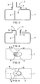
Figure 2 shows the tank ofFigure 1 with an ascending tube in transport position, -
Figure 3 shows a schematic cross-sectional side view of the depositing tank, -
Figure 4 shows a cross-sectional side view of the tank ofFigure 3 with the ascending tube in transport position, -
Figure 5 shows a top view of the container ofFigure 3 , and -
Figure 6 shows a top view of the depositing tank in the situation ofFigure 4 . - For the sake of clarity, in the figures some embodiments of the invention are shown in a simplified form. Like reference numerals refer to like parts in the figures.
-
Figure 1 shows a depositing tank. The depositing tank comprises abody 1, which is configured for allowing the container to be buried in the ground. Preferably thebody 1 is made of plastic, such as polyethylene PE or polypropylene PP or some other suitable plastic material. - The container further comprises an
ascending tube 2 arranged in thebody 1. Theascending tube 2 includes atube part 3, which extends above the ground when the container is in use. Theascending tube 2 further includes abase 4 that is integral with thetube part 3. - The
ascending tube 2 is configured to be detachable from thebody 1, whereby the ascending tube may be arranged partly inside thebody 1 during the transport of the container in a manner shown inFigure 2 . - The
base 4 of theascending tube 2 comprises aflange 5, and when the container is in use theascending tube 2 is attached to thebody 1, to a connectingend 6 provided in thebody 1. Theflange 5 is thus set over the connectingend 6. The connectingend 6 is a vertical collar that surrounds the hole in the upper part of thebody 1. A seal is arranged between theflange 5 and the connectingend 6 such that thebody 1 and the ascendingtube 2 will be tightly fitted and the joint concerned will not leak. Theflange 5 thus constitutes a sleeve that is arranged over the connectingend 6. The ascendingtube 2 and thebody 1 may also be interconnected with screws or bolts, whereby thebase 4 may be designed to conform to the outer surface of the hole in thebody 1 and a suitable seal is arranged between thebase 4 and thebody 1. Between thetube part 3 and thebase 4 of the ascendingtube 2 there is further provided a stiffening rib 7. The stiffening rib 7 reinforces the structure of the ascendingtube 2. -
Figure 3 also illustrates how the ascendingtube 2 is arranged in connection with thebody 1. - Thus, the attaching figures show a depositing tank, in which there is a
partition wall 8 or a plurality ofpartition walls 8 inside thecontainer body 1. Thepartition walls 8 divide the interior of the container into chambers. As it appears fromFigure 5 , thetube part 3 of the ascendingtube 2 is arranged such that all chambers inside the container may be serviced through the ascendingtube 3. -
Figures 4 and 6 , in turn, illustrate how the eccentric placement of thetube part 3 of the ascending tube in thebase 4 enables the tube part of the ascending tube being arranged in a chamber of the container during transport without thepartition walls 8 preventing the tube part from being placed inside the container. InFigure 6 ,partition walls 8 that remain invisible behind the ascendingtube 2 and thecontainer body 1 are indicated by broken lines. - If the hole in the
container body 1 is arranged to be sufficiently large, and correspondingly, thebase 4 of the ascendingtube 2 is sufficiently large and thetube part 3 is sufficiently small, thetube part 3 may also be arranged in a centralized manner in relation to thebase 4, but nevertheless the tube part could be placed inside a container chamber. When thetube part 3 is arranged eccentrically to thebase 4, a hole to be made in thebody 1 need not be large as a whole, and yet it is possible to place the tube part inside the chamber. In addition, eccentricity makes it possible that during transport thebase 4 is supported throughout to the rims of the hole in thecontainer 1. - The
container 1 is still further provided withlugs 9, by means of which the ascendingtube 2 may be secured firmly into place for transport. Said lugs may also be utilized for holding the ascendingtube 2 in place, when the container is in normal use. It is possible to connect to the lugs 9 a strap, a rope or a binding line by which the ascendingtube 2 is held in place. - There may be one, two or
more lugs 9 for securing the ascendingtube 2. - The
container body 1 is further provided with arecess 10. Therecess 10 may be arranged at the end of thebody 1 and it is intended for accommodating a distribution well during transport. Namely, subsequent to the depositing tank there is typically arranged a separate distribution well. The distribution well to be transported to the installation site together with the depositing tank can be transported attached to therecess 10. The container further comprises adowel pin 11. The dowel pin is designed in size and shape to correspond to a pipe that is inserted in an inlet of the distribution well. Thus, the distribution well inlet may be arranged in thedowel pin 11. Thecontainer body 1 further compriseslugs 12. Thus, the distribution well may be firmly attached to thebody 1 by means of thedowel pin 11 and thelugs 12 for transport. Thanks to thedowel pin 11, twolugs 12, to which the strap, the rope or the connecting line are to be connected, will typically suffice for securing the distribution well. - Instead of the
dowel pin 11, it is possible to use another aligning element, such as a rib, a notch or another suitable structural element. In that case the aligning element is not necessarily supported to the inlet of the distribution well, but it may be supported to some other shape in the distribution well. - On the sides, i.e. flanks, of the
container body 1 there are arranged transport mounts 13. In a normal use position the container is naturally in a position shown inFigure 1 , i.e. the ascendingtube 2 points upwardly. When the transport mounts 13 have been arranged on the sides of thebody 1, the container is transported to the installation site on its side, i.e. the transport mounts pointing downwardly. - The transport mounts 13 are arranged on the first side and a second side opposite to the first side. This allows a plurality of containers being superimposed during transport.
- The transport mounts 13 are provided such that on the first side of the container the transport mounts are concave. It is thus advantageous to transport the container with these concave mounts downwardly. The transport mounts 13 on the other side of the container are convex. Then, the convex transport mounts 13 point upwardly during transport. It will be relatively easy to place another container with concave downwardly pointing transport mounts on top of the convex transport mounts 13. Consequently, the concave transport mounts 13 of the upper container will fit smoothly and firmly against the convex transport mounts 13 of the lower container.
- In some cases the features set forth in this application may be used as such, irrespective of other features. On the other hand, features set forth in this application may be combined, where necessary, to provide various combinations.
- The drawings and the relating description are only intended to illustrate the inventive idea. The details of the invention may vary within the scope of the claims.
- So, the container to which the presented features are applied, may be, for instance, a depositing tank as indicated in the attached drawings. Also, the container may be another container intended for installation in the ground, such as a sewage tank or any other liquid tank, a well, such as a distribution well, or a corresponding container or well. Further, if the container comprises partition walls, the container may be a depositing tank or a small-scale purifying plant or another corresponding container having two or more chambers inside the body. In addition to or instead of the ascending tube or a section thereof it is possible to transport inside the body also other parts or accessories relating to the container completely or such that part of them is located inside the body. These parts or accessories may include inlet and outlet connections, inlet and outlet pipes, filter bed pipes, joints and branches, etc. During transport the ascending tube may also be mounted in its use position, and then the ascending tube will not be at all inside the body during transport. If the
container body 1 is sufficiently large, it is possible to make the hole for the ascendingtube base 4 in thebody 1 so large that relatively large pieces may be transported in the interior of thebody 1. The capacity of thebody 1 may vary, for instance, between 500 and 5000 litres. If the capacity of thebody 1 is sufficient, it is possible to transport a distribution well inside it, for instance.
Claims (3)
- A container having a body (1) that is configured for underground installation and comprising a top, a bottom and side walls, i.e. flanks, the top being provided with an ascending tube (2), at least one first flank of the body (1) is provided with transport mounts (13) on the exterior of the body (1) for trans-porting the container the first flank pointing downwards and the ascending tube (2) pointing sidewards, characterized in that the transport mounts (13) are arranged on two opposing flanks of the body (1), and that the transport mounts (13) on the first flank of the body (1) are concave and the transport mounts (13) on the second flank of the body (1) are convex.
- The container of claim 1,characterized in that the bottom of the container is flat.
- A method of transporting a container, comprising the steps of:providing a first container having a body (1) that is configured for underground installation and comprising a top, a bottom and side walls, i.e. flanks, the top being provided with an ascending tube (2), the container also having transport mounts (13) on at least one first flank of the body (1) on the exterior of the body (1) andtransporting the first container such that the first flank with the transport mounts (13) points downwards and the ascending tube (2) points sidewards-, characterized in that the transport mounts (13) are arranged on two opposing flanks of the body (1), whereby the transport mounts (13) on the first flank of the body (1) are concave and the transport mounts (13) on the second flank of the body (1) are convex and that at least a second identical container is transported on top of the first one, whereby the containers support on the transport mounts (13) of one another; and whereby during transport the concave transport mounts (13) point downwardly and the convextransport mounts (13) point upwardly and the concave transport mounts (13) of the second container fit against the convex transport mounts (13) of the first container.
Priority Applications (1)
| Application Number | Priority Date | Filing Date | Title |
|---|---|---|---|
| PL10175413T PL2251277T3 (en) | 2005-12-23 | 2006-12-21 | Tank for underground assembly and the method of its transport |
Applications Claiming Priority (2)
| Application Number | Priority Date | Filing Date | Title |
|---|---|---|---|
| FI20055700A FI20055700L (en) | 2005-12-23 | 2005-12-23 | Tank |
| EP06126843A EP1801035B8 (en) | 2005-12-23 | 2006-12-21 | Container for underground installation |
Related Parent Applications (2)
| Application Number | Title | Priority Date | Filing Date |
|---|---|---|---|
| EP06126843.9 Division | 2006-12-21 | ||
| EP06126843A Division EP1801035B8 (en) | 2005-12-23 | 2006-12-21 | Container for underground installation |
Publications (3)
| Publication Number | Publication Date |
|---|---|
| EP2251277A1 EP2251277A1 (en) | 2010-11-17 |
| EP2251277B1 true EP2251277B1 (en) | 2015-04-15 |
| EP2251277B8 EP2251277B8 (en) | 2015-06-17 |
Family
ID=35510778
Family Applications (2)
| Application Number | Title | Priority Date | Filing Date |
|---|---|---|---|
| EP10175413.3A Active EP2251277B8 (en) | 2005-12-23 | 2006-12-21 | Container for underground installation and method of transporting the same |
| EP06126843A Active EP1801035B8 (en) | 2005-12-23 | 2006-12-21 | Container for underground installation |
Family Applications After (1)
| Application Number | Title | Priority Date | Filing Date |
|---|---|---|---|
| EP06126843A Active EP1801035B8 (en) | 2005-12-23 | 2006-12-21 | Container for underground installation |
Country Status (7)
| Country | Link |
|---|---|
| EP (2) | EP2251277B8 (en) |
| AT (1) | ATE480480T1 (en) |
| DE (1) | DE602006016718D1 (en) |
| DK (2) | DK1801035T3 (en) |
| FI (1) | FI20055700L (en) |
| NO (1) | NO338752B1 (en) |
| PL (1) | PL2251277T3 (en) |
Families Citing this family (4)
| Publication number | Priority date | Publication date | Assignee | Title |
|---|---|---|---|---|
| DE102007020399B4 (en) * | 2007-04-27 | 2009-12-31 | Roth, Manfred, Dipl.-Volksw. | Tank, especially underground tank |
| PL2085326T3 (en) * | 2008-02-04 | 2013-03-29 | Graf Plastics Gmbh | Method for producing a plastic tank and plastic tank |
| FI20165351A7 (en) * | 2016-04-21 | 2017-10-22 | Oy U Cont Ltd | Intermodal fluid tank and system for fluid dispensing |
| US11326335B2 (en) * | 2017-06-30 | 2022-05-10 | South East Water Corporation | Tank for pressure sewer installation |
Family Cites Families (12)
| Publication number | Priority date | Publication date | Assignee | Title |
|---|---|---|---|---|
| AU2684071A (en) * | 1971-04-06 | 1972-09-28 | ||
| DE9115953U1 (en) * | 1991-12-21 | 1992-02-27 | ABS Pumpen AG, 53797 Lohmar | Spherical tank for gases, liquids or pasty masses |
| JPH10174985A (en) * | 1996-12-17 | 1998-06-30 | Sekisui Chem Co Ltd | Septic tank |
| US6024242A (en) * | 1996-12-24 | 2000-02-15 | Eidson Steel Products, Inc. | Removably insertable internal containment reservoir |
| JP4006744B2 (en) * | 1997-09-30 | 2007-11-14 | 株式会社日立ハウステック | Bulkhead frame and septic tank |
| JP2000136540A (en) * | 1998-10-30 | 2000-05-16 | Shikoku Sanyu Kasei Kk | Manhole rise frame for large septic tank |
| DE19911009A1 (en) * | 1999-03-12 | 2000-09-14 | Fusion Kunststoff Gmbh | Rainwater collection tank consists of cylindrical body with threaded opening for height adjustable intake/inspection socket |
| BE1013186A6 (en) * | 1999-12-21 | 2001-10-02 | Tank Shop Jan Verbeeck B V B A | Fuel tank for use underground |
| JP2002309631A (en) * | 2001-04-17 | 2002-10-23 | Ishikawajima Constr Materials Co Ltd | Water tank |
| US20040188447A1 (en) * | 2002-01-23 | 2004-09-30 | Todd Bolzer | Underground storage tank |
| US7178686B2 (en) * | 2002-01-23 | 2007-02-20 | Snyder Industries | Rotationally molded subterranean tank with riser |
| DE202004008058U1 (en) * | 2004-05-17 | 2004-07-22 | Vtg-Lehnkering Reederei Gmbh | Transport and storage containers |
-
2005
- 2005-12-23 FI FI20055700A patent/FI20055700L/en not_active Application Discontinuation
-
2006
- 2006-12-21 DK DK06126843.9T patent/DK1801035T3/en active
- 2006-12-21 EP EP10175413.3A patent/EP2251277B8/en active Active
- 2006-12-21 DK DK10175413.3T patent/DK2251277T3/en active
- 2006-12-21 EP EP06126843A patent/EP1801035B8/en active Active
- 2006-12-21 DE DE602006016718T patent/DE602006016718D1/en active Active
- 2006-12-21 AT AT06126843T patent/ATE480480T1/en not_active IP Right Cessation
- 2006-12-21 PL PL10175413T patent/PL2251277T3/en unknown
- 2006-12-22 NO NO20065986A patent/NO338752B1/en unknown
Also Published As
| Publication number | Publication date |
|---|---|
| PL2251277T3 (en) | 2015-10-30 |
| NO338752B1 (en) | 2016-10-17 |
| DE602006016718D1 (en) | 2010-10-21 |
| FI20055700A7 (en) | 2007-06-24 |
| FI20055700L (en) | 2007-06-24 |
| EP1801035B1 (en) | 2010-09-08 |
| DK1801035T3 (en) | 2010-12-06 |
| EP1801035A1 (en) | 2007-06-27 |
| EP2251277B8 (en) | 2015-06-17 |
| EP1801035B8 (en) | 2011-01-19 |
| ATE480480T1 (en) | 2010-09-15 |
| EP2251277A1 (en) | 2010-11-17 |
| NO20065986L (en) | 2007-06-25 |
| FI20055700A0 (en) | 2005-12-23 |
| DK2251277T3 (en) | 2015-07-13 |
Similar Documents
| Publication | Publication Date | Title |
|---|---|---|
| CA2714329C (en) | Storage tank containment apparatus | |
| CA2314819C (en) | Septic waste treatment system | |
| US9377032B2 (en) | Mobile concrete pump | |
| US20020069840A1 (en) | Double walled fuel tank with integral generator set mounting frame | |
| US11230853B2 (en) | Large capacity above ground impoundment tank | |
| US11548725B2 (en) | Cover systems, tank covering methods, and pipe retention systems | |
| EP1801035B1 (en) | Container for underground installation | |
| US6491054B1 (en) | Method and apparatus for constructing modular fluid containment tanks | |
| US20070164552A1 (en) | Fluid containment system | |
| US7000800B2 (en) | Storage tank assembly | |
| US7631659B2 (en) | Fluid tank | |
| AU9721398A (en) | Outlet fitting and container having the same and method for containing a material and draining and filling the same | |
| USRE49933E1 (en) | Above ground water tank fill/drain system | |
| US20130160860A1 (en) | Load box for storage tank containment | |
| US20140048532A1 (en) | Water storage tank | |
| JPH0436230B2 (en) | ||
| EP2685108A1 (en) | Oil tank | |
| JPH11208772A (en) | Underground embedded liquid storage container | |
| US6695002B1 (en) | Outside drop for manhole | |
| US11009178B2 (en) | Pump package frame | |
| RU15899U1 (en) | MULTI-SECTION PASSING WELL | |
| WO2017127894A1 (en) | Improvements in the discharge of bulk liquids | |
| JPH1179284A (en) | Underground buried fuel container | |
| US20030234001A1 (en) | Device for compensating pressure in a motor vehicle tank | |
| JP2009174595A (en) | Joint |
Legal Events
| Date | Code | Title | Description |
|---|---|---|---|
| PUAI | Public reference made under article 153(3) epc to a published international application that has entered the european phase |
Free format text: ORIGINAL CODE: 0009012 |
|
| AC | Divisional application: reference to earlier application |
Ref document number: 1801035 Country of ref document: EP Kind code of ref document: P |
|
| AK | Designated contracting states |
Kind code of ref document: A1 Designated state(s): AT BE BG CH CY CZ DE DK EE ES FI FR GB GR HU IE IS IT LI LT LU LV MC NL PL PT RO SE SI SK TR |
|
| RIN1 | Information on inventor provided before grant (corrected) |
Inventor name: STRAND, JOHAN Inventor name: FORSSELL, FREDRIK Inventor name: TAST, NIILA |
|
| 17P | Request for examination filed |
Effective date: 20110513 |
|
| 17Q | First examination report despatched |
Effective date: 20120309 |
|
| RAP1 | Party data changed (applicant data changed or rights of an application transferred) |
Owner name: UPONOR INNOVATION AB |
|
| REG | Reference to a national code |
Ref country code: DE Ref legal event code: R079 Ref document number: 602006045173 Country of ref document: DE Free format text: PREVIOUS MAIN CLASS: B65D0088060000 Ipc: B65D0088000000 |
|
| RIC1 | Information provided on ipc code assigned before grant |
Ipc: B65D 88/76 20060101ALI20140918BHEP Ipc: B65D 88/02 20060101ALI20140918BHEP Ipc: B65D 88/00 20060101AFI20140918BHEP Ipc: B65D 90/00 20060101ALN20140918BHEP Ipc: B65D 88/06 20060101ALI20140918BHEP Ipc: B65D 90/10 20060101ALI20140918BHEP |
|
| GRAP | Despatch of communication of intention to grant a patent |
Free format text: ORIGINAL CODE: EPIDOSNIGR1 |
|
| INTG | Intention to grant announced |
Effective date: 20141107 |
|
| GRAS | Grant fee paid |
Free format text: ORIGINAL CODE: EPIDOSNIGR3 |
|
| GRAA | (expected) grant |
Free format text: ORIGINAL CODE: 0009210 |
|
| AC | Divisional application: reference to earlier application |
Ref document number: 1801035 Country of ref document: EP Kind code of ref document: P |
|
| AK | Designated contracting states |
Kind code of ref document: B1 Designated state(s): AT BE BG CH CY CZ DE DK EE ES FI FR GB GR HU IE IS IT LI LT LU LV MC NL PL PT RO SE SI SK TR |
|
| REG | Reference to a national code |
Ref country code: GB Ref legal event code: FG4D Ref country code: CH Ref legal event code: EP |
|
| REG | Reference to a national code |
Ref country code: IE Ref legal event code: FG4D |
|
| REG | Reference to a national code |
Ref country code: AT Ref legal event code: REF Ref document number: 721812 Country of ref document: AT Kind code of ref document: T Effective date: 20150515 |
|
| RAP2 | Party data changed (patent owner data changed or rights of a patent transferred) |
Owner name: UPONOR INFRA OY |
|
| REG | Reference to a national code |
Ref country code: DE Ref legal event code: R096 Ref document number: 602006045173 Country of ref document: DE Effective date: 20150521 |
|
| REG | Reference to a national code |
Ref country code: DK Ref legal event code: T3 Effective date: 20150710 |
|
| REG | Reference to a national code |
Ref country code: SE Ref legal event code: TRGR |
|
| REG | Reference to a national code |
Ref country code: NL Ref legal event code: VDEP Effective date: 20150415 |
|
| REG | Reference to a national code |
Ref country code: AT Ref legal event code: MK05 Ref document number: 721812 Country of ref document: AT Kind code of ref document: T Effective date: 20150415 |
|
| REG | Reference to a national code |
Ref country code: LT Ref legal event code: MG4D |
|
| PG25 | Lapsed in a contracting state [announced via postgrant information from national office to epo] |
Ref country code: NL Free format text: LAPSE BECAUSE OF FAILURE TO SUBMIT A TRANSLATION OF THE DESCRIPTION OR TO PAY THE FEE WITHIN THE PRESCRIBED TIME-LIMIT Effective date: 20150415 |
|
| PG25 | Lapsed in a contracting state [announced via postgrant information from national office to epo] |
Ref country code: PT Free format text: LAPSE BECAUSE OF FAILURE TO SUBMIT A TRANSLATION OF THE DESCRIPTION OR TO PAY THE FEE WITHIN THE PRESCRIBED TIME-LIMIT Effective date: 20150817 Ref country code: LT Free format text: LAPSE BECAUSE OF FAILURE TO SUBMIT A TRANSLATION OF THE DESCRIPTION OR TO PAY THE FEE WITHIN THE PRESCRIBED TIME-LIMIT Effective date: 20150415 Ref country code: ES Free format text: LAPSE BECAUSE OF FAILURE TO SUBMIT A TRANSLATION OF THE DESCRIPTION OR TO PAY THE FEE WITHIN THE PRESCRIBED TIME-LIMIT Effective date: 20150415 |
|
| REG | Reference to a national code |
Ref country code: PL Ref legal event code: T3 |
|
| REG | Reference to a national code |
Ref country code: EE Ref legal event code: FG4A Ref document number: E010995 Country of ref document: EE Effective date: 20150715 |
|
| PG25 | Lapsed in a contracting state [announced via postgrant information from national office to epo] |
Ref country code: AT Free format text: LAPSE BECAUSE OF FAILURE TO SUBMIT A TRANSLATION OF THE DESCRIPTION OR TO PAY THE FEE WITHIN THE PRESCRIBED TIME-LIMIT Effective date: 20150415 Ref country code: IS Free format text: LAPSE BECAUSE OF FAILURE TO SUBMIT A TRANSLATION OF THE DESCRIPTION OR TO PAY THE FEE WITHIN THE PRESCRIBED TIME-LIMIT Effective date: 20150815 Ref country code: GR Free format text: LAPSE BECAUSE OF FAILURE TO SUBMIT A TRANSLATION OF THE DESCRIPTION OR TO PAY THE FEE WITHIN THE PRESCRIBED TIME-LIMIT Effective date: 20150716 |
|
| REG | Reference to a national code |
Ref country code: DE Ref legal event code: R097 Ref document number: 602006045173 Country of ref document: DE |
|
| PGFP | Annual fee paid to national office [announced via postgrant information from national office to epo] |
Ref country code: DE Payment date: 20151211 Year of fee payment: 10 Ref country code: EE Payment date: 20151211 Year of fee payment: 10 |
|
| PLBE | No opposition filed within time limit |
Free format text: ORIGINAL CODE: 0009261 |
|
| STAA | Information on the status of an ep patent application or granted ep patent |
Free format text: STATUS: NO OPPOSITION FILED WITHIN TIME LIMIT |
|
| PG25 | Lapsed in a contracting state [announced via postgrant information from national office to epo] |
Ref country code: RO Free format text: LAPSE BECAUSE OF NON-PAYMENT OF DUE FEES Effective date: 20150415 Ref country code: CZ Free format text: LAPSE BECAUSE OF FAILURE TO SUBMIT A TRANSLATION OF THE DESCRIPTION OR TO PAY THE FEE WITHIN THE PRESCRIBED TIME-LIMIT Effective date: 20150415 Ref country code: SK Free format text: LAPSE BECAUSE OF FAILURE TO SUBMIT A TRANSLATION OF THE DESCRIPTION OR TO PAY THE FEE WITHIN THE PRESCRIBED TIME-LIMIT Effective date: 20150415 |
|
| PGFP | Annual fee paid to national office [announced via postgrant information from national office to epo] |
Ref country code: LV Payment date: 20151211 Year of fee payment: 10 |
|
| 26N | No opposition filed |
Effective date: 20160118 |
|
| PG25 | Lapsed in a contracting state [announced via postgrant information from national office to epo] |
Ref country code: IT Free format text: LAPSE BECAUSE OF FAILURE TO SUBMIT A TRANSLATION OF THE DESCRIPTION OR TO PAY THE FEE WITHIN THE PRESCRIBED TIME-LIMIT Effective date: 20150415 |
|
| PG25 | Lapsed in a contracting state [announced via postgrant information from national office to epo] |
Ref country code: BE Free format text: LAPSE BECAUSE OF NON-PAYMENT OF DUE FEES Effective date: 20151231 Ref country code: SI Free format text: LAPSE BECAUSE OF FAILURE TO SUBMIT A TRANSLATION OF THE DESCRIPTION OR TO PAY THE FEE WITHIN THE PRESCRIBED TIME-LIMIT Effective date: 20150415 |
|
| PG25 | Lapsed in a contracting state [announced via postgrant information from national office to epo] |
Ref country code: LU Free format text: LAPSE BECAUSE OF FAILURE TO SUBMIT A TRANSLATION OF THE DESCRIPTION OR TO PAY THE FEE WITHIN THE PRESCRIBED TIME-LIMIT Effective date: 20151221 Ref country code: MC Free format text: LAPSE BECAUSE OF FAILURE TO SUBMIT A TRANSLATION OF THE DESCRIPTION OR TO PAY THE FEE WITHIN THE PRESCRIBED TIME-LIMIT Effective date: 20150415 |
|
| REG | Reference to a national code |
Ref country code: CH Ref legal event code: PL |
|
| GBPC | Gb: european patent ceased through non-payment of renewal fee |
Effective date: 20151221 |
|
| PG25 | Lapsed in a contracting state [announced via postgrant information from national office to epo] |
Ref country code: BE Free format text: LAPSE BECAUSE OF FAILURE TO SUBMIT A TRANSLATION OF THE DESCRIPTION OR TO PAY THE FEE WITHIN THE PRESCRIBED TIME-LIMIT Effective date: 20150415 |
|
| REG | Reference to a national code |
Ref country code: IE Ref legal event code: MM4A |
|
| REG | Reference to a national code |
Ref country code: FR Ref legal event code: ST Effective date: 20160831 |
|
| PG25 | Lapsed in a contracting state [announced via postgrant information from national office to epo] |
Ref country code: CH Free format text: LAPSE BECAUSE OF NON-PAYMENT OF DUE FEES Effective date: 20151231 Ref country code: LI Free format text: LAPSE BECAUSE OF NON-PAYMENT OF DUE FEES Effective date: 20151231 Ref country code: IE Free format text: LAPSE BECAUSE OF NON-PAYMENT OF DUE FEES Effective date: 20151221 Ref country code: GB Free format text: LAPSE BECAUSE OF NON-PAYMENT OF DUE FEES Effective date: 20151221 |
|
| PG25 | Lapsed in a contracting state [announced via postgrant information from national office to epo] |
Ref country code: FR Free format text: LAPSE BECAUSE OF NON-PAYMENT OF DUE FEES Effective date: 20151231 |
|
| PG25 | Lapsed in a contracting state [announced via postgrant information from national office to epo] |
Ref country code: BG Free format text: LAPSE BECAUSE OF FAILURE TO SUBMIT A TRANSLATION OF THE DESCRIPTION OR TO PAY THE FEE WITHIN THE PRESCRIBED TIME-LIMIT Effective date: 20150415 Ref country code: HU Free format text: LAPSE BECAUSE OF FAILURE TO SUBMIT A TRANSLATION OF THE DESCRIPTION OR TO PAY THE FEE WITHIN THE PRESCRIBED TIME-LIMIT; INVALID AB INITIO Effective date: 20061221 |
|
| PG25 | Lapsed in a contracting state [announced via postgrant information from national office to epo] |
Ref country code: CY Free format text: LAPSE BECAUSE OF FAILURE TO SUBMIT A TRANSLATION OF THE DESCRIPTION OR TO PAY THE FEE WITHIN THE PRESCRIBED TIME-LIMIT Effective date: 20150415 |
|
| REG | Reference to a national code |
Ref country code: DE Ref legal event code: R119 Ref document number: 602006045173 Country of ref document: DE |
|
| REG | Reference to a national code |
Ref country code: EE Ref legal event code: MM4A Ref document number: E010995 Country of ref document: EE Effective date: 20161231 |
|
| PG25 | Lapsed in a contracting state [announced via postgrant information from national office to epo] |
Ref country code: LV Free format text: LAPSE BECAUSE OF NON-PAYMENT OF DUE FEES Effective date: 20161221 Ref country code: TR Free format text: LAPSE BECAUSE OF FAILURE TO SUBMIT A TRANSLATION OF THE DESCRIPTION OR TO PAY THE FEE WITHIN THE PRESCRIBED TIME-LIMIT Effective date: 20150415 |
|
| PG25 | Lapsed in a contracting state [announced via postgrant information from national office to epo] |
Ref country code: EE Free format text: LAPSE BECAUSE OF NON-PAYMENT OF DUE FEES Effective date: 20161231 |
|
| PG25 | Lapsed in a contracting state [announced via postgrant information from national office to epo] |
Ref country code: DE Free format text: LAPSE BECAUSE OF NON-PAYMENT OF DUE FEES Effective date: 20170701 |
|
| PGFP | Annual fee paid to national office [announced via postgrant information from national office to epo] |
Ref country code: DK Payment date: 20171215 Year of fee payment: 12 |
|
| PGFP | Annual fee paid to national office [announced via postgrant information from national office to epo] |
Ref country code: PL Payment date: 20171124 Year of fee payment: 12 |
|
| REG | Reference to a national code |
Ref country code: DK Ref legal event code: EBP Effective date: 20181231 |
|
| PG25 | Lapsed in a contracting state [announced via postgrant information from national office to epo] |
Ref country code: DK Free format text: LAPSE BECAUSE OF NON-PAYMENT OF DUE FEES Effective date: 20181231 |
|
| PG25 | Lapsed in a contracting state [announced via postgrant information from national office to epo] |
Ref country code: PL Free format text: LAPSE BECAUSE OF NON-PAYMENT OF DUE FEES Effective date: 20181221 |
|
| P01 | Opt-out of the competence of the unified patent court (upc) registered |
Effective date: 20230602 |
|
| PGFP | Annual fee paid to national office [announced via postgrant information from national office to epo] |
Ref country code: FI Payment date: 20251223 Year of fee payment: 20 |
|
| PGFP | Annual fee paid to national office [announced via postgrant information from national office to epo] |
Ref country code: SE Payment date: 20251219 Year of fee payment: 20 |