EP2251255A2 - A sectional pontoon bridge - Google Patents
A sectional pontoon bridge Download PDFInfo
- Publication number
- EP2251255A2 EP2251255A2 EP10461514A EP10461514A EP2251255A2 EP 2251255 A2 EP2251255 A2 EP 2251255A2 EP 10461514 A EP10461514 A EP 10461514A EP 10461514 A EP10461514 A EP 10461514A EP 2251255 A2 EP2251255 A2 EP 2251255A2
- Authority
- EP
- European Patent Office
- Prior art keywords
- pontoon
- cassette
- cassettes
- main compartment
- previous
- Prior art date
- Legal status (The legal status is an assumption and is not a legal conclusion. Google has not performed a legal analysis and makes no representation as to the accuracy of the status listed.)
- Granted
Links
Images

Classifications
-
- E—FIXED CONSTRUCTIONS
- E01—CONSTRUCTION OF ROADS, RAILWAYS, OR BRIDGES
- E01D—CONSTRUCTION OF BRIDGES, ELEVATED ROADWAYS OR VIADUCTS; ASSEMBLY OF BRIDGES
- E01D15/00—Movable or portable bridges; Floating bridges
- E01D15/14—Floating bridges, e.g. pontoon bridges
-
- B—PERFORMING OPERATIONS; TRANSPORTING
- B63—SHIPS OR OTHER WATERBORNE VESSELS; RELATED EQUIPMENT
- B63B—SHIPS OR OTHER WATERBORNE VESSELS; EQUIPMENT FOR SHIPPING
- B63B35/00—Vessels or similar floating structures specially adapted for specific purposes and not otherwise provided for
- B63B35/34—Pontoons
-
- B—PERFORMING OPERATIONS; TRANSPORTING
- B63—SHIPS OR OTHER WATERBORNE VESSELS; RELATED EQUIPMENT
- B63B—SHIPS OR OTHER WATERBORNE VESSELS; EQUIPMENT FOR SHIPPING
- B63B3/00—Hulls characterised by their structure or component parts
- B63B3/02—Hulls assembled from prefabricated sub-units
- B63B3/08—Hulls assembled from prefabricated sub-units with detachably-connected sub-units
-
- B—PERFORMING OPERATIONS; TRANSPORTING
- B63—SHIPS OR OTHER WATERBORNE VESSELS; RELATED EQUIPMENT
- B63B—SHIPS OR OTHER WATERBORNE VESSELS; EQUIPMENT FOR SHIPPING
- B63B34/00—Vessels specially adapted for water sports or leisure; Body-supporting devices specially adapted for water sports or leisure
- B63B34/50—Body-supporting buoyant devices, e.g. bathing boats or water cycles
Definitions
- the invention relates to pontoon bridges.
- the currently known and used buoyant systems comprise individual buoyant segments, which are objects made of metal or plastics, having different dimensions and a closed form.
- the ready-to-use buoyant segments must have factory-provided leak tightness to provide appropriate displacement.
- Their disadvantages include high transport volume and requirement for abundant transport means, accompanying equipment (e.g. cranes) and service personnel.
- Large and heavy pontoons forming military buoyant systems of this type are known from the Polish patent PL158579 and the Polish patent application PL297453.
- the object of the invention is a cassette for a pontoon bridge, the cassette comprising a main compartment, a pontoon having an elastic cushion installed in the main compartment, a split bottom of the main compartment with movable lids configured to open under pressure of the extending pontoon when the pontoon is inflated such as to allow extension of the pontoon outside the main compartment.
- the movable lids of the split bottom can be further configured to close and fold the pontoon into the main compartment when the pontoon is deflated.
- Each of the movable lids of the split bottom can be connected with the main compartment by hinges with a spring mechanism configured to bias the movable lids to closed position.
- the split bottom can be a two-lid bottom comprising two movable lids installed opposite each other.
- the cassette may further comprise an elastic net attached to the movable lids of the split bottom and configured to keep the bottom part of the pontoon substantially above the bottom edges of the movable lids of the split bottom.
- the elastic net can be further configured to limit the maximum opening of the movable lids of the split bottom.
- the main compartment can be made of lightweight plastics.
- the main compartment can be joined with a roadway surface for moving vehicles.
- the cassette may further comprise connectors for connecting the cassette with other cassettes.
- the pontoon can be inflatable with an inflating system having pressure connectors for connecting the inflating system with inflating systems of other cassettes.
- the movable lids of the split bottom can be made of reinforced material to provide ballistic cover for the pontoon.
- the cushion of the pontoon can be made of punctrure-resistant, reinforced elastic or semi-elastic material.
- Another object of the present invention is a pontoon bridge formed of a plurality of the cassettes according to the invention.
- a plurality of cassettes can be connected with connectors limiting the range of movement between the cassettes.
- a plurality of cassettes may have an inflating system for inflating the pontoons and wherein the inflating systems of the cassettes are connected together with pressure connectors.
- the cassette pontoon bridge according to the invention has a modular structure and is composed of individual cassettes 1, as shown in Fig. 1 .
- a plurality of cassettes 1 can be immediately assembled and used to build the cassette pontoon bridge.
- the main element of construction of a single cassette 1 of the cassette pontoon bridge is a main compartment 9 of the cassette 1 made of lightweight plastics, such as polyurethane, polyethylene.
- a pontoon 2, having a high strength elastic cushion, is installed in the compartment 9 of the cassette 1.
- the split bottom 3 comprises a movable left and a movable right lid, installed on lid hinges together with a spring mechanism 4.
- the lids are closed by means of the spring mechanism 4.
- An elastic net 6 is attached to both lids of the cassette 1, which stabilizes the pontoon 2 in the open position and facilitates its proper folding and sets its placement for the transport position.
- the net 6 also closes the split bottom 3.
- the cushion of the pontoon 2 is inflated with compressed air by an inflating system, the elements of which are joined between individual cassettes 1 by quick-release pressure connectors 5.
- the top portion of the cassette 1 is joined with a roadway surface 7 for moving vehicles.
- the cassettes 1 are interconnected by means of intersegmental connectors 8, which provide adequately strong connections between individual cassettes 1 of the cassette pontoon bridge and limit the range of movement between the cassettes 1.
- a single cassette 1 is characterized by a construction allowing easy and quick folding to a transport position, as shown in Fig. 2 .
- the cushion of the pontoon 2 is packed up into the main chamber of the cassette 1, which is closed by the split bottom 3. Therefore, the volume of the cassette 1 can be decreased, which provides saving of the transport space and increases the mobility of the cassette pontoon bridge.
- the cassette 1 has a variable displacement.
- the element providing the variable displacement during use is a high-strength, in particular resistant to punctures, elastic or semi-elastic cushion of the pontoon 2, for example made of polyurethane.
- the cushion can be filled with compressed air and when filled, it provides adequate buoyant force.
- the level of filling defines the displacement of the cassette 1, which is equal to the difference between the buoyant force and the dead weight of the cassette 1. Therefore, the displacement of the cassette pontoon bridge, as well as its draught, can be varied by varying the level of filling of individual cassettes 1.
- the lids of the split bottom 3 are opened by means of change of pressure inside the cushion of the pontoon 2, during operation of the filing system, and can be easily closed by means of the spring mechanism 4 aided by the net 6 extended within the compartment 9 of the cassette 1, which also folds the cushion of the pontoon 2 into the cassette 1.
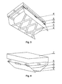
- the pontoon 2, during the operation of filling opens by means of its pressure both lids of the split bottom 3 aside and stretches the net 6 attached to the lids, as shown in Fig. 4 .
- the opened lids in the working position, as shown in Fig. 3 are used as ballistic cover of the cassette pontoon bridge for military applications.
- the lids of the split bottom 3 are made of reinforced material. When air is released, the pontoon 2 is folded by the elastic net 6, which pulls it inside the cassette 1.
- the open lids of the split bottom 3 protect the cushion of the pontoon 2 at its sides from damage.
- the elastic net 6 extending between the lids of the split bottom 3. Both lids of the split bottom 3, when ajar, are opened by the pontoon 2 during use of the filling system.
- the net 6 keeps the lids of the split bottom 3 in a proper position and limits the lids from extensive opening. Therefore, the elastic net 6 is configured to limit the maximum opening of the movable lids of the split bottom 3. As seen in the figures, the elastic net 6 is configured to keep the bottom part of the pontoon substantially above the bottom edges of the movable lids of the split bottom 3.
- the cassette pontoon bridge according to the invention is to be understood as an object formed by any assembly of individual cassettes having configurations and dimensions equal to the multiple of dimensions of the individual cassettes shown in the drawings.
- the cassette pontoon bridge may be used to form floating bridges, floating footbridges, floating platforms, floating wharfs, floating jetties, ferries or rafts.
- the cassette pontoon bridge can be used to form stationary and temporary objects. It can be used in many public, commercial, tourist, recreational or amusement applications. However, it is particularly useful for military applications, as well as during natural or building disasters. In particular, the possibility of positioning of the cassette pontoon bridge below the water surface (the crossing camouflage) is particularly useful for military applications.
- the objects formed of individual cassettes of the cassette pontoon bridge may also function as temporary crossing, in place of stationary crossing objects which have been damaged or broken.
- the cassette pontoon bridge may be also used as a substitute crossing during repairs and conservation of stationary crossing objects and other elements of water infrastructure.
- the crossing may be two-way.
- the possibility of arbitrary forming of the dimensions and configuration of the cassette pontoon bridge is achieved by full repeatability and variable displacement of individual cassettes.
- the cassettes can be re-used for many assembly and disassembly operations.
- the leak-tightness and displacement can be guaranteed for various exploitation conditions.
- the cassettes are highly susceptible to damages and destruction, due to reinforced cushion of the pontoon and covers formed by the lids of the split bottom. All of the above increases the possible applications of the cassette pontoon bridge.
- the displacement of the cassette pontoon bridge may be regulated, as it depends on the level of filling of the pontoons with compressed air.
- the constructional features of the cassettes provide easy transport of a higher number of cassettes in small cargo space, quick assembly of long runs of the cassette pontoon bridge and compact construction due to foldable pontoon. This allows easy storage and transport of the elements of the system. Due to simple construction and small number of elements, the assembly of fully functional floating objects can be achieved by sparse crew without special training.
Landscapes
- Engineering & Computer Science (AREA)
- Chemical & Material Sciences (AREA)
- Combustion & Propulsion (AREA)
- Mechanical Engineering (AREA)
- Ocean & Marine Engineering (AREA)
- Architecture (AREA)
- Civil Engineering (AREA)
- Structural Engineering (AREA)
- Bridges Or Land Bridges (AREA)
Abstract
Description
- The invention relates to pontoon bridges.
- The currently known and used buoyant systems comprise individual buoyant segments, which are objects made of metal or plastics, having different dimensions and a closed form. The ready-to-use buoyant segments must have factory-provided leak tightness to provide appropriate displacement. Their disadvantages include high transport volume and requirement for abundant transport means, accompanying equipment (e.g. cranes) and service personnel. Large and heavy pontoons forming military buoyant systems of this type are known from the Polish patent PL158579 and the Polish patent application PL297453.
- In particular, the steel segments known from the Polish patent PL158579, due to their high dead weight and large dimensions, allow one truck to transport only two segments. Loading and unloading of these pontoons, as well as their service and assembly on water need numerous, highly qualified crew and specialized equipment. All of that limits the scope of applications of such heavy constructions. The lack of mobility makes them unusable especially in hard cross-country conditions, which limits operational capabilities. Exploitation of such constructions is very expensive. Steel pontoons require providing appropriate conditions of storage (in particular, large space) and anti-corrosion protection. They also require maintenance of additional sites with specially adapted vehicles for transport of individual segments and additional equipment necessary for assembly, disassembly and maintenance in operating condition. The complicated exploitation procedures of heavy metal pontoons having closed form require also maintaining numerous crew and appropriate training of service personnel. The mobility of such objects is very limited due to their constructional features. Use of such constructions involves complicated connecting mechanisms. The above features result in high exploitation costs of such constructions.
- The object of the invention is a cassette for a pontoon bridge, the cassette comprising a main compartment, a pontoon having an elastic cushion installed in the main compartment, a split bottom of the main compartment with movable lids configured to open under pressure of the extending pontoon when the pontoon is inflated such as to allow extension of the pontoon outside the main compartment.
- The movable lids of the split bottom can be further configured to close and fold the pontoon into the main compartment when the pontoon is deflated.
- Each of the movable lids of the split bottom can be connected with the main compartment by hinges with a spring mechanism configured to bias the movable lids to closed position.
- The split bottom can be a two-lid bottom comprising two movable lids installed opposite each other.
- The cassette may further comprise an elastic net attached to the movable lids of the split bottom and configured to keep the bottom part of the pontoon substantially above the bottom edges of the movable lids of the split bottom.
- The elastic net can be further configured to limit the maximum opening of the movable lids of the split bottom.
- The main compartment can be made of lightweight plastics.
- The main compartment can be joined with a roadway surface for moving vehicles.
- The cassette may further comprise connectors for connecting the cassette with other cassettes.
- The pontoon can be inflatable with an inflating system having pressure connectors for connecting the inflating system with inflating systems of other cassettes.
- The movable lids of the split bottom can be made of reinforced material to provide ballistic cover for the pontoon.
- The cushion of the pontoon can be made of punctrure-resistant, reinforced elastic or semi-elastic material.
- Another object of the present invention is a pontoon bridge formed of a plurality of the cassettes according to the invention.
- A plurality of cassettes can be connected with connectors limiting the range of movement between the cassettes.
- A plurality of cassettes may have an inflating system for inflating the pontoons and wherein the inflating systems of the cassettes are connected together with pressure connectors.
- The present invention is shown by way of exemplary embodiment on a drawing, in which:
-
Fig. 1 shows a cassette pontoon bridge comprising individual cassettes. -
Fig. 2 shows the cassette in a transport position. -
Fig. 3 shows the cassette in a working position. -
Fig. 4 shows the cassette in an intermediate position. - The cassette pontoon bridge according to the invention has a modular structure and is composed of
individual cassettes 1, as shown inFig. 1 . A plurality ofcassettes 1 can be immediately assembled and used to build the cassette pontoon bridge. - The main element of construction of a
single cassette 1 of the cassette pontoon bridge is amain compartment 9 of thecassette 1 made of lightweight plastics, such as polyurethane, polyethylene. A pontoon 2, having a high strength elastic cushion, is installed in thecompartment 9 of thecassette 1. In a transport position, the cushion of the pontoon 2 is packed up inside themain compartment 9, which is closed by asplit bottom 3. Thesplit bottom 3 comprises a movable left and a movable right lid, installed on lid hinges together with aspring mechanism 4. The lids are closed by means of thespring mechanism 4. Anelastic net 6 is attached to both lids of thecassette 1, which stabilizes the pontoon 2 in the open position and facilitates its proper folding and sets its placement for the transport position. The net 6 also closes thesplit bottom 3. The cushion of the pontoon 2 is inflated with compressed air by an inflating system, the elements of which are joined betweenindividual cassettes 1 by quick-release pressure connectors 5. The top portion of thecassette 1 is joined with aroadway surface 7 for moving vehicles. Thecassettes 1 are interconnected by means ofintersegmental connectors 8, which provide adequately strong connections betweenindividual cassettes 1 of the cassette pontoon bridge and limit the range of movement between thecassettes 1. - A
single cassette 1 is characterized by a construction allowing easy and quick folding to a transport position, as shown inFig. 2 . In the transport position, the cushion of the pontoon 2 is packed up into the main chamber of thecassette 1, which is closed by thesplit bottom 3. Therefore, the volume of thecassette 1 can be decreased, which provides saving of the transport space and increases the mobility of the cassette pontoon bridge. - The
cassette 1 has a variable displacement. The element providing the variable displacement during use is a high-strength, in particular resistant to punctures, elastic or semi-elastic cushion of the pontoon 2, for example made of polyurethane. The cushion can be filled with compressed air and when filled, it provides adequate buoyant force. The level of filling defines the displacement of thecassette 1, which is equal to the difference between the buoyant force and the dead weight of thecassette 1. Therefore, the displacement of the cassette pontoon bridge, as well as its draught, can be varied by varying the level of filling ofindividual cassettes 1. - The lids of the
split bottom 3 are opened by means of change of pressure inside the cushion of the pontoon 2, during operation of the filing system, and can be easily closed by means of thespring mechanism 4 aided by thenet 6 extended within thecompartment 9 of thecassette 1, which also folds the cushion of the pontoon 2 into thecassette 1. The pontoon 2, during the operation of filling, opens by means of its pressure both lids of thesplit bottom 3 aside and stretches thenet 6 attached to the lids, as shown inFig. 4 . The opened lids in the working position, as shown inFig. 3 , are used as ballistic cover of the cassette pontoon bridge for military applications. To provide adequate ballistic cover, the lids of thesplit bottom 3 are made of reinforced material. When air is released, the pontoon 2 is folded by theelastic net 6, which pulls it inside thecassette 1. The open lids of thesplit bottom 3 protect the cushion of the pontoon 2 at its sides from damage. - An important element of the
cassette 1 of the cassette pontoon bridge is theelastic net 6 extending between the lids of thesplit bottom 3. Both lids of thesplit bottom 3, when ajar, are opened by the pontoon 2 during use of the filling system. The net 6 keeps the lids of thesplit bottom 3 in a proper position and limits the lids from extensive opening. Therefore, theelastic net 6 is configured to limit the maximum opening of the movable lids of thesplit bottom 3. As seen in the figures, theelastic net 6 is configured to keep the bottom part of the pontoon substantially above the bottom edges of the movable lids of thesplit bottom 3. - Therefore, the cassette pontoon bridge according to the invention is to be understood as an object formed by any assembly of individual cassettes having configurations and dimensions equal to the multiple of dimensions of the individual cassettes shown in the drawings. The cassette pontoon bridge may be used to form floating bridges, floating footbridges, floating platforms, floating wharfs, floating jetties, ferries or rafts.
- The cassette pontoon bridge can be used to form stationary and temporary objects. It can be used in many public, commercial, tourist, recreational or amusement applications. However, it is particularly useful for military applications, as well as during natural or building disasters. In particular, the possibility of positioning of the cassette pontoon bridge below the water surface (the crossing camouflage) is particularly useful for military applications.
- The objects formed of individual cassettes of the cassette pontoon bridge may also function as temporary crossing, in place of stationary crossing objects which have been damaged or broken. The cassette pontoon bridge may be also used as a substitute crossing during repairs and conservation of stationary crossing objects and other elements of water infrastructure. The crossing may be two-way.
- The possibility of arbitrary forming of the dimensions and configuration of the cassette pontoon bridge is achieved by full repeatability and variable displacement of individual cassettes. The cassettes can be re-used for many assembly and disassembly operations. The leak-tightness and displacement can be guaranteed for various exploitation conditions. The cassettes are highly susceptible to damages and destruction, due to reinforced cushion of the pontoon and covers formed by the lids of the split bottom. All of the above increases the possible applications of the cassette pontoon bridge. The displacement of the cassette pontoon bridge may be regulated, as it depends on the level of filling of the pontoons with compressed air.
- The constructional features of the cassettes provide easy transport of a higher number of cassettes in small cargo space, quick assembly of long runs of the cassette pontoon bridge and compact construction due to foldable pontoon. This allows easy storage and transport of the elements of the system. Due to simple construction and small number of elements, the assembly of fully functional floating objects can be achieved by sparse crew without special training.
Claims (15)
- A cassette for a pontoon bridge, the cassette (1) comprising:- a main compartment (9),- a pontoon (2) having an elastic cushion installed in the main compartment (9),- a split bottom (3) of the main compartment (9) with movable lids configured to open under pressure of the extending pontoon (2) when the pontoon (2) is inflated such as to allow extension of the pontoon (2) outside the main compartment (9).
- The cassette according to claim 1, wherein the movable lids of the split bottom (3) are further configured to close and fold the pontoon (2) into the main compartment (9) when the pontoon (2) is deflated.
- The cassette according to any of claims 1-2, wherein each of the movable lids of the split bottom (3) is connected with the main compartment (9) by hinges with a spring mechanism (4) configured to bias the movable lids to closed position.
- The cassette according to any of previous claims, wherein the split bottom (3) is a two-lid bottom comprising two movable lids installed opposite each other.
- The cassette according to any of previous claims, further comprising an elastic net (6) attached to the movable lids of the split bottom (3) and configured to keep the bottom part of the pontoon substantially above the bottom edges of the movable lids of the split bottom (3).
- The cassette according to any of previous claims, wherein the elastic net (6) is further configured to limit the maximum opening of the movable lids of the split bottom (3).
- The cassette according to any of previous claims, wherein the main compartment (9) is made of lightweight plastics.
- The cassette according to any of previous claims, wherein the main compartment (9) is joined with a roadway surface (7) for moving vehicles.
- The cassette according to any of previous claims, further comprising connectors (8) for connecting the cassette (1) with other cassettes (1).
- The cassette according to any of previous claims, wherein the pontoon (2) is inflatable with an inflating system having pressure connectors (5) for connecting the inflating system with inflating systems of other cassettes (1).
- The cassette according to any of previous claims, wherein the movable lids of the split bottom (3) are made of reinforced material to provide ballistic cover for the pontoon (2).
- The cassette according to any of previous claims, wherein the cushion of the pontoon (2) is made of punctrure-resistant, reinforced elastic or semi-elastic material.
- A pontoon bridge formed of a plurality of the cassettes (1) according to any of claims 1-11.
- The pontoon bridge according to claim 13, wherein a plurality of cassettes (1) are connected with connectors (8) limiting the range of movement between the cassettes (1).
- The pontoon bridge according to claim 13 or 14, wherein a plurality of cassettes have an inflating system for inflating the pontoons (2) and wherein the inflating systems of the cassettes (1) are connected together with pressure connectors (5).
Priority Applications (3)
| Application Number | Priority Date | Filing Date | Title |
|---|---|---|---|
| PL388739A PL388739A1 (en) | 2009-05-06 | 2009-05-06 | Caisson pontoon bridge |
| EP10461514.1A EP2251255B1 (en) | 2009-05-06 | 2010-05-05 | A sectional pontoon bridge |
| PL10461514T PL2251255T3 (en) | 2009-05-06 | 2010-05-05 | A sectional pontoon bridge |
Applications Claiming Priority (2)
| Application Number | Priority Date | Filing Date | Title |
|---|---|---|---|
| PL388739A PL388739A1 (en) | 2009-05-06 | 2009-05-06 | Caisson pontoon bridge |
| EP10461514.1A EP2251255B1 (en) | 2009-05-06 | 2010-05-05 | A sectional pontoon bridge |
Publications (3)
| Publication Number | Publication Date |
|---|---|
| EP2251255A2 true EP2251255A2 (en) | 2010-11-17 |
| EP2251255A3 EP2251255A3 (en) | 2011-08-17 |
| EP2251255B1 EP2251255B1 (en) | 2013-05-01 |
Family
ID=42635023
Family Applications (1)
| Application Number | Title | Priority Date | Filing Date |
|---|---|---|---|
| EP10461514.1A Not-in-force EP2251255B1 (en) | 2009-05-06 | 2010-05-05 | A sectional pontoon bridge |
Country Status (2)
| Country | Link |
|---|---|
| EP (1) | EP2251255B1 (en) |
| PL (2) | PL388739A1 (en) |
Cited By (13)
| Publication number | Priority date | Publication date | Assignee | Title |
|---|---|---|---|---|
| CN103993555A (en) * | 2013-02-20 | 2014-08-20 | 朱培池 | Air inflation pontoon bridge |
| CN104195935A (en) * | 2014-08-04 | 2014-12-10 | 中冶天工上海十三冶建设有限公司 | Pontoon working face device used for constructing buildings in water |
| CN105113381A (en) * | 2015-09-07 | 2015-12-02 | 田玉海 | Inflatable floating bridge |
| EP2570551A3 (en) * | 2011-06-17 | 2016-07-20 | Wojskowa Akademia Techniczna im. Jaroslawa Dabrowskiego | A cassette of a floating bridge |
| JP2017066802A (en) * | 2015-10-01 | 2017-04-06 | 三井造船鉄構エンジニアリング株式会社 | Connection structure of floating body for floating pier |
| US9688364B1 (en) * | 2013-03-15 | 2017-06-27 | Patriot3, Inc. | Modular floatable dock section, dock assembly, and method for constructing a dock assembly |
| CN107620256A (en) * | 2016-07-16 | 2018-01-23 | 赵彦杰 | Expedient float bridge |
| CN108411765A (en) * | 2018-05-14 | 2018-08-17 | 武汉速安达建筑橡塑制品有限公司 | A kind of emergent pontoon bridge of quick inflation/deflation |
| CN108532444A (en) * | 2018-03-09 | 2018-09-14 | 湖北华舟重工应急装备股份有限公司 | A kind of rolling logs in trestle |
| CN109466706A (en) * | 2019-01-07 | 2019-03-15 | 孙立强 | A kind of floating platform |
| CN116479743A (en) * | 2023-04-11 | 2023-07-25 | 黑龙江省龙建路桥第四工程有限公司 | A New Type of Carbon Fiber Composite Emergency Water Floating Bridge |
| CN117779588A (en) * | 2024-01-10 | 2024-03-29 | 西南交通大学 | Portable water-filled river crossing device for clearing danger and rushing across narrow river valleys in dangerous mountainous areas |
| PL442488A1 (en) * | 2022-10-10 | 2024-04-15 | Wojskowy Instytut Techniki Inżynieryjnej Im. Profesora Józefa Kosackiego | Assault pontoon bridge |
Families Citing this family (3)
| Publication number | Priority date | Publication date | Assignee | Title |
|---|---|---|---|---|
| RU175961U1 (en) * | 2017-04-13 | 2017-12-25 | Татьяна Константиновна Скобенникова | SECTION REPAIR SITE |
| RU178523U1 (en) * | 2017-10-13 | 2018-04-06 | Лев Георгиевич Делюсто | PONTOON BRIDGE |
| RU190230U1 (en) * | 2019-02-04 | 2019-06-24 | ФЕДЕРАЛЬНОЕ ГОСУДАРСТВЕННОЕ КАЗЕННОЕ ВОЕННОЕ ОБРАЗОВАТЕЛЬНОЕ УЧРЕЖДЕНИЕ ВЫСШЕГО ОБРАЗОВАНИЯ "ТЮМЕНСКОЕ ВЫСШЕЕ ВОЕННО-ИНЖЕНЕРНОЕ КОМАНДНОЕ УЧИЛИЩЕ ИМЕНИ МАРШАЛА ИНЖЕНЕРНЫХ ВОЙСК А.И. ПРОШЛЯКОВА" Министерства обороны Российской Федерации | Pneumopodflowing model of the tape bridge pontoon park PP-2005 |
Citations (2)
| Publication number | Priority date | Publication date | Assignee | Title |
|---|---|---|---|---|
| PL158579B2 (en) | 1989-08-29 | 1992-09-30 | Segmented, ballastiess vessel, in particular floating stage or quay | |
| PL297453A1 (en) | 1993-02-23 | 1994-09-05 | Kazimierz Kowalski | Built-up pontoons |
Family Cites Families (2)
| Publication number | Priority date | Publication date | Assignee | Title |
|---|---|---|---|---|
| FR2079688A5 (en) * | 1970-02-10 | 1971-11-12 | Hir J P Le | |
| GB8919663D0 (en) * | 1989-08-31 | 1989-10-11 | White S New Designs Ltd | Improved buoyant structure suitable for floating bridges |
-
2009
- 2009-05-06 PL PL388739A patent/PL388739A1/en not_active Application Discontinuation
-
2010
- 2010-05-05 EP EP10461514.1A patent/EP2251255B1/en not_active Not-in-force
- 2010-05-05 PL PL10461514T patent/PL2251255T3/en unknown
Patent Citations (2)
| Publication number | Priority date | Publication date | Assignee | Title |
|---|---|---|---|---|
| PL158579B2 (en) | 1989-08-29 | 1992-09-30 | Segmented, ballastiess vessel, in particular floating stage or quay | |
| PL297453A1 (en) | 1993-02-23 | 1994-09-05 | Kazimierz Kowalski | Built-up pontoons |
Cited By (15)
| Publication number | Priority date | Publication date | Assignee | Title |
|---|---|---|---|---|
| EP2570551A3 (en) * | 2011-06-17 | 2016-07-20 | Wojskowa Akademia Techniczna im. Jaroslawa Dabrowskiego | A cassette of a floating bridge |
| CN103993555A (en) * | 2013-02-20 | 2014-08-20 | 朱培池 | Air inflation pontoon bridge |
| US9688364B1 (en) * | 2013-03-15 | 2017-06-27 | Patriot3, Inc. | Modular floatable dock section, dock assembly, and method for constructing a dock assembly |
| CN104195935A (en) * | 2014-08-04 | 2014-12-10 | 中冶天工上海十三冶建设有限公司 | Pontoon working face device used for constructing buildings in water |
| CN105113381A (en) * | 2015-09-07 | 2015-12-02 | 田玉海 | Inflatable floating bridge |
| JP2017066802A (en) * | 2015-10-01 | 2017-04-06 | 三井造船鉄構エンジニアリング株式会社 | Connection structure of floating body for floating pier |
| CN107620256A (en) * | 2016-07-16 | 2018-01-23 | 赵彦杰 | Expedient float bridge |
| CN108532444A (en) * | 2018-03-09 | 2018-09-14 | 湖北华舟重工应急装备股份有限公司 | A kind of rolling logs in trestle |
| CN108411765A (en) * | 2018-05-14 | 2018-08-17 | 武汉速安达建筑橡塑制品有限公司 | A kind of emergent pontoon bridge of quick inflation/deflation |
| CN108411765B (en) * | 2018-05-14 | 2023-12-19 | 武汉速安达建筑橡塑制品有限公司 | Emergency floating bridge capable of being rapidly inflated and deflated |
| CN109466706A (en) * | 2019-01-07 | 2019-03-15 | 孙立强 | A kind of floating platform |
| CN109466706B (en) * | 2019-01-07 | 2020-08-28 | 南京溧水高新创业投资管理有限公司 | Combined floating platform |
| PL442488A1 (en) * | 2022-10-10 | 2024-04-15 | Wojskowy Instytut Techniki Inżynieryjnej Im. Profesora Józefa Kosackiego | Assault pontoon bridge |
| CN116479743A (en) * | 2023-04-11 | 2023-07-25 | 黑龙江省龙建路桥第四工程有限公司 | A New Type of Carbon Fiber Composite Emergency Water Floating Bridge |
| CN117779588A (en) * | 2024-01-10 | 2024-03-29 | 西南交通大学 | Portable water-filled river crossing device for clearing danger and rushing across narrow river valleys in dangerous mountainous areas |
Also Published As
| Publication number | Publication date |
|---|---|
| PL2251255T3 (en) | 2013-09-30 |
| EP2251255A3 (en) | 2011-08-17 |
| EP2251255B1 (en) | 2013-05-01 |
| PL388739A1 (en) | 2010-05-24 |
Similar Documents
| Publication | Publication Date | Title |
|---|---|---|
| EP2251255B1 (en) | A sectional pontoon bridge | |
| US8418631B2 (en) | Pallet design with buoyant characteristics | |
| Russell et al. | Portable and rapidly deployable bridges: Historical perspective and recent technology developments | |
| US5197821A (en) | Lightweight, rapid deployment oil spill containment boom | |
| CN107905086B (en) | A folding motorized pontoon | |
| US9162739B2 (en) | Inflatable portable platform | |
| US9199706B2 (en) | Water rescue device | |
| US20140042044A1 (en) | Convertible container | |
| US4561376A (en) | Transportable pontoon | |
| CN202345890U (en) | High-power outboard engine driven fast moving operating floating table | |
| WO2015081149A1 (en) | Single net capture marine barrier system | |
| CN109183718B (en) | Folding expansion type inflatable anti-collision connecting bridge | |
| US10858126B2 (en) | Deformable closure mechanism | |
| JP2014510662A (en) | Convertible container | |
| EP2760730B1 (en) | Simplified actuation device for moving fender members | |
| CN109850115B (en) | A mobile tethered balloon storage | |
| EP2570551B1 (en) | A cassette of a floating bridge | |
| USRE30438E (en) | Inflatable barrier for substances floating on water | |
| EP2301786A1 (en) | Waterproof bag | |
| US10259539B1 (en) | Portable lightweight apparatus for transferring heavy loads | |
| KR20030079651A (en) | Armoured Foldaway Inflatable Floating Device and Amphibious Vehicle | |
| CN111535150A (en) | Rigid-flex combined folding pontoon | |
| US3523318A (en) | Collapsible pontoon bridge | |
| CN102424097A (en) | High-power outboard engine driven quick moving operation floating platform | |
| GB2293796A (en) | Safety improvements for vehicular ferries and other vessels. |
Legal Events
| Date | Code | Title | Description |
|---|---|---|---|
| PUAI | Public reference made under article 153(3) epc to a published international application that has entered the european phase |
Free format text: ORIGINAL CODE: 0009012 |
|
| AK | Designated contracting states |
Kind code of ref document: A2 Designated state(s): AL AT BE BG CH CY CZ DE DK EE ES FI FR GB GR HR HU IE IS IT LI LT LU LV MC MK MT NL NO PL PT RO SE SI SK SM TR |
|
| AX | Request for extension of the european patent |
Extension state: BA ME RS |
|
| PUAL | Search report despatched |
Free format text: ORIGINAL CODE: 0009013 |
|
| AK | Designated contracting states |
Kind code of ref document: A3 Designated state(s): AL AT BE BG CH CY CZ DE DK EE ES FI FR GB GR HR HU IE IS IT LI LT LU LV MC MK MT NL NO PL PT RO SE SI SK SM TR |
|
| AX | Request for extension of the european patent |
Extension state: BA ME RS |
|
| RIC1 | Information provided on ipc code assigned before grant |
Ipc: B63B 35/36 20060101AFI20110711BHEP Ipc: E01D 15/20 20060101ALI20110711BHEP Ipc: B63B 7/08 20060101ALI20110711BHEP Ipc: E01D 15/14 20060101ALI20110711BHEP Ipc: B63B 35/34 20060101ALI20110711BHEP |
|
| 17P | Request for examination filed |
Effective date: 20120214 |
|
| 17Q | First examination report despatched |
Effective date: 20120718 |
|
| GRAP | Despatch of communication of intention to grant a patent |
Free format text: ORIGINAL CODE: EPIDOSNIGR1 |
|
| RAP1 | Party data changed (applicant data changed or rights of an application transferred) |
Owner name: WOJSKOWA AKADEMIA TECHNICZNA |
|
| GRAS | Grant fee paid |
Free format text: ORIGINAL CODE: EPIDOSNIGR3 |
|
| GRAA | (expected) grant |
Free format text: ORIGINAL CODE: 0009210 |
|
| AK | Designated contracting states |
Kind code of ref document: B1 Designated state(s): AL AT BE BG CH CY CZ DE DK EE ES FI FR GB GR HR HU IE IS IT LI LT LU LV MC MK MT NL NO PL PT RO SE SI SK SM TR |
|
| REG | Reference to a national code |
Ref country code: GB Ref legal event code: FG4D |
|
| REG | Reference to a national code |
Ref country code: AT Ref legal event code: REF Ref document number: 609752 Country of ref document: AT Kind code of ref document: T Effective date: 20130515 Ref country code: CH Ref legal event code: EP |
|
| REG | Reference to a national code |
Ref country code: IE Ref legal event code: FG4D |
|
| REG | Reference to a national code |
Ref country code: DE Ref legal event code: R096 Ref document number: 602010006656 Country of ref document: DE Effective date: 20130627 |
|
| REG | Reference to a national code |
Ref country code: AT Ref legal event code: MK05 Ref document number: 609752 Country of ref document: AT Kind code of ref document: T Effective date: 20130501 |
|
| REG | Reference to a national code |
Ref country code: PL Ref legal event code: T3 |
|
| REG | Reference to a national code |
Ref country code: NL Ref legal event code: VDEP Effective date: 20130501 |
|
| REG | Reference to a national code |
Ref country code: LT Ref legal event code: MG4D |
|
| PG25 | Lapsed in a contracting state [announced via postgrant information from national office to epo] |
Ref country code: AT Free format text: LAPSE BECAUSE OF FAILURE TO SUBMIT A TRANSLATION OF THE DESCRIPTION OR TO PAY THE FEE WITHIN THE PRESCRIBED TIME-LIMIT Effective date: 20130501 Ref country code: FI Free format text: LAPSE BECAUSE OF FAILURE TO SUBMIT A TRANSLATION OF THE DESCRIPTION OR TO PAY THE FEE WITHIN THE PRESCRIBED TIME-LIMIT Effective date: 20130501 Ref country code: SI Free format text: LAPSE BECAUSE OF FAILURE TO SUBMIT A TRANSLATION OF THE DESCRIPTION OR TO PAY THE FEE WITHIN THE PRESCRIBED TIME-LIMIT Effective date: 20130501 Ref country code: SE Free format text: LAPSE BECAUSE OF FAILURE TO SUBMIT A TRANSLATION OF THE DESCRIPTION OR TO PAY THE FEE WITHIN THE PRESCRIBED TIME-LIMIT Effective date: 20130501 Ref country code: PT Free format text: LAPSE BECAUSE OF FAILURE TO SUBMIT A TRANSLATION OF THE DESCRIPTION OR TO PAY THE FEE WITHIN THE PRESCRIBED TIME-LIMIT Effective date: 20130902 Ref country code: NO Free format text: LAPSE BECAUSE OF FAILURE TO SUBMIT A TRANSLATION OF THE DESCRIPTION OR TO PAY THE FEE WITHIN THE PRESCRIBED TIME-LIMIT Effective date: 20130801 Ref country code: LT Free format text: LAPSE BECAUSE OF FAILURE TO SUBMIT A TRANSLATION OF THE DESCRIPTION OR TO PAY THE FEE WITHIN THE PRESCRIBED TIME-LIMIT Effective date: 20130501 Ref country code: GR Free format text: LAPSE BECAUSE OF FAILURE TO SUBMIT A TRANSLATION OF THE DESCRIPTION OR TO PAY THE FEE WITHIN THE PRESCRIBED TIME-LIMIT Effective date: 20130802 Ref country code: IS Free format text: LAPSE BECAUSE OF FAILURE TO SUBMIT A TRANSLATION OF THE DESCRIPTION OR TO PAY THE FEE WITHIN THE PRESCRIBED TIME-LIMIT Effective date: 20130901 Ref country code: ES Free format text: LAPSE BECAUSE OF FAILURE TO SUBMIT A TRANSLATION OF THE DESCRIPTION OR TO PAY THE FEE WITHIN THE PRESCRIBED TIME-LIMIT Effective date: 20130812 |
|
| PG25 | Lapsed in a contracting state [announced via postgrant information from national office to epo] |
Ref country code: CY Free format text: LAPSE BECAUSE OF FAILURE TO SUBMIT A TRANSLATION OF THE DESCRIPTION OR TO PAY THE FEE WITHIN THE PRESCRIBED TIME-LIMIT Effective date: 20130501 Ref country code: BG Free format text: LAPSE BECAUSE OF FAILURE TO SUBMIT A TRANSLATION OF THE DESCRIPTION OR TO PAY THE FEE WITHIN THE PRESCRIBED TIME-LIMIT Effective date: 20130801 Ref country code: HR Free format text: LAPSE BECAUSE OF FAILURE TO SUBMIT A TRANSLATION OF THE DESCRIPTION OR TO PAY THE FEE WITHIN THE PRESCRIBED TIME-LIMIT Effective date: 20130501 |
|
| PG25 | Lapsed in a contracting state [announced via postgrant information from national office to epo] |
Ref country code: LV Free format text: LAPSE BECAUSE OF FAILURE TO SUBMIT A TRANSLATION OF THE DESCRIPTION OR TO PAY THE FEE WITHIN THE PRESCRIBED TIME-LIMIT Effective date: 20130501 |
|
| PG25 | Lapsed in a contracting state [announced via postgrant information from national office to epo] |
Ref country code: MC Free format text: LAPSE BECAUSE OF FAILURE TO SUBMIT A TRANSLATION OF THE DESCRIPTION OR TO PAY THE FEE WITHIN THE PRESCRIBED TIME-LIMIT Effective date: 20130501 Ref country code: SK Free format text: LAPSE BECAUSE OF FAILURE TO SUBMIT A TRANSLATION OF THE DESCRIPTION OR TO PAY THE FEE WITHIN THE PRESCRIBED TIME-LIMIT Effective date: 20130501 Ref country code: CZ Free format text: LAPSE BECAUSE OF FAILURE TO SUBMIT A TRANSLATION OF THE DESCRIPTION OR TO PAY THE FEE WITHIN THE PRESCRIBED TIME-LIMIT Effective date: 20130501 Ref country code: DK Free format text: LAPSE BECAUSE OF FAILURE TO SUBMIT A TRANSLATION OF THE DESCRIPTION OR TO PAY THE FEE WITHIN THE PRESCRIBED TIME-LIMIT Effective date: 20130501 Ref country code: BE Free format text: LAPSE BECAUSE OF FAILURE TO SUBMIT A TRANSLATION OF THE DESCRIPTION OR TO PAY THE FEE WITHIN THE PRESCRIBED TIME-LIMIT Effective date: 20130501 Ref country code: EE Free format text: LAPSE BECAUSE OF FAILURE TO SUBMIT A TRANSLATION OF THE DESCRIPTION OR TO PAY THE FEE WITHIN THE PRESCRIBED TIME-LIMIT Effective date: 20130501 |
|
| REG | Reference to a national code |
Ref country code: IE Ref legal event code: MM4A |
|
| PG25 | Lapsed in a contracting state [announced via postgrant information from national office to epo] |
Ref country code: NL Free format text: LAPSE BECAUSE OF FAILURE TO SUBMIT A TRANSLATION OF THE DESCRIPTION OR TO PAY THE FEE WITHIN THE PRESCRIBED TIME-LIMIT Effective date: 20130501 Ref country code: IT Free format text: LAPSE BECAUSE OF FAILURE TO SUBMIT A TRANSLATION OF THE DESCRIPTION OR TO PAY THE FEE WITHIN THE PRESCRIBED TIME-LIMIT Effective date: 20130501 Ref country code: RO Free format text: LAPSE BECAUSE OF FAILURE TO SUBMIT A TRANSLATION OF THE DESCRIPTION OR TO PAY THE FEE WITHIN THE PRESCRIBED TIME-LIMIT Effective date: 20130501 |
|
| PLBE | No opposition filed within time limit |
Free format text: ORIGINAL CODE: 0009261 |
|
| STAA | Information on the status of an ep patent application or granted ep patent |
Free format text: STATUS: NO OPPOSITION FILED WITHIN TIME LIMIT |
|
| 26N | No opposition filed |
Effective date: 20140204 |
|
| PG25 | Lapsed in a contracting state [announced via postgrant information from national office to epo] |
Ref country code: IE Free format text: LAPSE BECAUSE OF NON-PAYMENT OF DUE FEES Effective date: 20130505 |
|
| REG | Reference to a national code |
Ref country code: DE Ref legal event code: R097 Ref document number: 602010006656 Country of ref document: DE Effective date: 20140204 |
|
| REG | Reference to a national code |
Ref country code: CH Ref legal event code: PL |
|
| PG25 | Lapsed in a contracting state [announced via postgrant information from national office to epo] |
Ref country code: LI Free format text: LAPSE BECAUSE OF NON-PAYMENT OF DUE FEES Effective date: 20140531 Ref country code: CH Free format text: LAPSE BECAUSE OF NON-PAYMENT OF DUE FEES Effective date: 20140531 |
|
| PG25 | Lapsed in a contracting state [announced via postgrant information from national office to epo] |
Ref country code: MT Free format text: LAPSE BECAUSE OF FAILURE TO SUBMIT A TRANSLATION OF THE DESCRIPTION OR TO PAY THE FEE WITHIN THE PRESCRIBED TIME-LIMIT Effective date: 20130501 |
|
| PG25 | Lapsed in a contracting state [announced via postgrant information from national office to epo] |
Ref country code: SM Free format text: LAPSE BECAUSE OF FAILURE TO SUBMIT A TRANSLATION OF THE DESCRIPTION OR TO PAY THE FEE WITHIN THE PRESCRIBED TIME-LIMIT Effective date: 20130501 |
|
| PG25 | Lapsed in a contracting state [announced via postgrant information from national office to epo] |
Ref country code: TR Free format text: LAPSE BECAUSE OF FAILURE TO SUBMIT A TRANSLATION OF THE DESCRIPTION OR TO PAY THE FEE WITHIN THE PRESCRIBED TIME-LIMIT Effective date: 20130501 |
|
| PG25 | Lapsed in a contracting state [announced via postgrant information from national office to epo] |
Ref country code: MK Free format text: LAPSE BECAUSE OF FAILURE TO SUBMIT A TRANSLATION OF THE DESCRIPTION OR TO PAY THE FEE WITHIN THE PRESCRIBED TIME-LIMIT Effective date: 20130501 Ref country code: LU Free format text: LAPSE BECAUSE OF NON-PAYMENT OF DUE FEES Effective date: 20130505 Ref country code: HU Free format text: LAPSE BECAUSE OF FAILURE TO SUBMIT A TRANSLATION OF THE DESCRIPTION OR TO PAY THE FEE WITHIN THE PRESCRIBED TIME-LIMIT; INVALID AB INITIO Effective date: 20100505 |
|
| REG | Reference to a national code |
Ref country code: FR Ref legal event code: PLFP Year of fee payment: 7 |
|
| REG | Reference to a national code |
Ref country code: FR Ref legal event code: PLFP Year of fee payment: 8 |
|
| REG | Reference to a national code |
Ref country code: FR Ref legal event code: PLFP Year of fee payment: 9 |
|
| PG25 | Lapsed in a contracting state [announced via postgrant information from national office to epo] |
Ref country code: AL Free format text: LAPSE BECAUSE OF FAILURE TO SUBMIT A TRANSLATION OF THE DESCRIPTION OR TO PAY THE FEE WITHIN THE PRESCRIBED TIME-LIMIT Effective date: 20130501 |
|
| PGFP | Annual fee paid to national office [announced via postgrant information from national office to epo] |
Ref country code: FR Payment date: 20200428 Year of fee payment: 11 Ref country code: DE Payment date: 20200429 Year of fee payment: 11 |
|
| PGFP | Annual fee paid to national office [announced via postgrant information from national office to epo] |
Ref country code: GB Payment date: 20200429 Year of fee payment: 11 Ref country code: PL Payment date: 20200428 Year of fee payment: 11 |
|
| REG | Reference to a national code |
Ref country code: DE Ref legal event code: R119 Ref document number: 602010006656 Country of ref document: DE |
|
| GBPC | Gb: european patent ceased through non-payment of renewal fee |
Effective date: 20210505 |
|
| PG25 | Lapsed in a contracting state [announced via postgrant information from national office to epo] |
Ref country code: GB Free format text: LAPSE BECAUSE OF NON-PAYMENT OF DUE FEES Effective date: 20210505 Ref country code: DE Free format text: LAPSE BECAUSE OF NON-PAYMENT OF DUE FEES Effective date: 20211201 |
|
| PG25 | Lapsed in a contracting state [announced via postgrant information from national office to epo] |
Ref country code: FR Free format text: LAPSE BECAUSE OF NON-PAYMENT OF DUE FEES Effective date: 20210531 |
|
| PG25 | Lapsed in a contracting state [announced via postgrant information from national office to epo] |
Ref country code: PL Free format text: LAPSE BECAUSE OF NON-PAYMENT OF DUE FEES Effective date: 20210505 |