EP2251224A1 - Electric vehicle driving device - Google Patents
Electric vehicle driving device Download PDFInfo
- Publication number
- EP2251224A1 EP2251224A1 EP09717856A EP09717856A EP2251224A1 EP 2251224 A1 EP2251224 A1 EP 2251224A1 EP 09717856 A EP09717856 A EP 09717856A EP 09717856 A EP09717856 A EP 09717856A EP 2251224 A1 EP2251224 A1 EP 2251224A1
- Authority
- EP
- European Patent Office
- Prior art keywords
- brake
- electric
- switching circuits
- switching
- vehicle driving
- Prior art date
- Legal status (The legal status is an assumption and is not a legal conclusion. Google has not performed a legal analysis and makes no representation as to the accuracy of the status listed.)
- Withdrawn
Links
Images






Classifications
-
- B—PERFORMING OPERATIONS; TRANSPORTING
- B60—VEHICLES IN GENERAL
- B60L—PROPULSION OF ELECTRICALLY-PROPELLED VEHICLES; SUPPLYING ELECTRIC POWER FOR AUXILIARY EQUIPMENT OF ELECTRICALLY-PROPELLED VEHICLES; ELECTRODYNAMIC BRAKE SYSTEMS FOR VEHICLES IN GENERAL; MAGNETIC SUSPENSION OR LEVITATION FOR VEHICLES; MONITORING OPERATING VARIABLES OF ELECTRICALLY-PROPELLED VEHICLES; ELECTRIC SAFETY DEVICES FOR ELECTRICALLY-PROPELLED VEHICLES
- B60L7/00—Electrodynamic brake systems for vehicles in general
- B60L7/10—Dynamic electric regenerative braking
- B60L7/16—Dynamic electric regenerative braking for vehicles comprising converters between the power source and the motor
-
- B—PERFORMING OPERATIONS; TRANSPORTING
- B60—VEHICLES IN GENERAL
- B60L—PROPULSION OF ELECTRICALLY-PROPELLED VEHICLES; SUPPLYING ELECTRIC POWER FOR AUXILIARY EQUIPMENT OF ELECTRICALLY-PROPELLED VEHICLES; ELECTRODYNAMIC BRAKE SYSTEMS FOR VEHICLES IN GENERAL; MAGNETIC SUSPENSION OR LEVITATION FOR VEHICLES; MONITORING OPERATING VARIABLES OF ELECTRICALLY-PROPELLED VEHICLES; ELECTRIC SAFETY DEVICES FOR ELECTRICALLY-PROPELLED VEHICLES
- B60L50/00—Electric propulsion with power supplied within the vehicle
- B60L50/10—Electric propulsion with power supplied within the vehicle using propulsion power supplied by engine-driven generators, e.g. generators driven by combustion engines
- B60L50/13—Electric propulsion with power supplied within the vehicle using propulsion power supplied by engine-driven generators, e.g. generators driven by combustion engines using AC generators and AC motors
-
- B—PERFORMING OPERATIONS; TRANSPORTING
- B60—VEHICLES IN GENERAL
- B60L—PROPULSION OF ELECTRICALLY-PROPELLED VEHICLES; SUPPLYING ELECTRIC POWER FOR AUXILIARY EQUIPMENT OF ELECTRICALLY-PROPELLED VEHICLES; ELECTRODYNAMIC BRAKE SYSTEMS FOR VEHICLES IN GENERAL; MAGNETIC SUSPENSION OR LEVITATION FOR VEHICLES; MONITORING OPERATING VARIABLES OF ELECTRICALLY-PROPELLED VEHICLES; ELECTRIC SAFETY DEVICES FOR ELECTRICALLY-PROPELLED VEHICLES
- B60L7/00—Electrodynamic brake systems for vehicles in general
- B60L7/02—Dynamic electric resistor braking
- B60L7/06—Dynamic electric resistor braking for vehicles propelled by AC motors
-
- B—PERFORMING OPERATIONS; TRANSPORTING
- B60—VEHICLES IN GENERAL
- B60L—PROPULSION OF ELECTRICALLY-PROPELLED VEHICLES; SUPPLYING ELECTRIC POWER FOR AUXILIARY EQUIPMENT OF ELECTRICALLY-PROPELLED VEHICLES; ELECTRODYNAMIC BRAKE SYSTEMS FOR VEHICLES IN GENERAL; MAGNETIC SUSPENSION OR LEVITATION FOR VEHICLES; MONITORING OPERATING VARIABLES OF ELECTRICALLY-PROPELLED VEHICLES; ELECTRIC SAFETY DEVICES FOR ELECTRICALLY-PROPELLED VEHICLES
- B60L7/00—Electrodynamic brake systems for vehicles in general
- B60L7/22—Dynamic electric resistor braking, combined with dynamic electric regenerative braking
-
- B—PERFORMING OPERATIONS; TRANSPORTING
- B60—VEHICLES IN GENERAL
- B60L—PROPULSION OF ELECTRICALLY-PROPELLED VEHICLES; SUPPLYING ELECTRIC POWER FOR AUXILIARY EQUIPMENT OF ELECTRICALLY-PROPELLED VEHICLES; ELECTRODYNAMIC BRAKE SYSTEMS FOR VEHICLES IN GENERAL; MAGNETIC SUSPENSION OR LEVITATION FOR VEHICLES; MONITORING OPERATING VARIABLES OF ELECTRICALLY-PROPELLED VEHICLES; ELECTRIC SAFETY DEVICES FOR ELECTRICALLY-PROPELLED VEHICLES
- B60L9/00—Electric propulsion with power supply external to the vehicle
- B60L9/16—Electric propulsion with power supply external to the vehicle using AC induction motors
-
- H—ELECTRICITY
- H02—GENERATION; CONVERSION OR DISTRIBUTION OF ELECTRIC POWER
- H02M—APPARATUS FOR CONVERSION BETWEEN AC AND AC, BETWEEN AC AND DC, OR BETWEEN DC AND DC, AND FOR USE WITH MAINS OR SIMILAR POWER SUPPLY SYSTEMS; CONVERSION OF DC OR AC INPUT POWER INTO SURGE OUTPUT POWER; CONTROL OR REGULATION THEREOF
- H02M7/00—Conversion of AC power input into DC power output; Conversion of DC power input into AC power output
- H02M7/66—Conversion of AC power input into DC power output; Conversion of DC power input into AC power output with possibility of reversal
- H02M7/68—Conversion of AC power input into DC power output; Conversion of DC power input into AC power output with possibility of reversal by static converters
- H02M7/72—Conversion of AC power input into DC power output; Conversion of DC power input into AC power output with possibility of reversal by static converters using discharge tubes with control electrode or semiconductor devices with control electrode
- H02M7/79—Conversion of AC power input into DC power output; Conversion of DC power input into AC power output with possibility of reversal by static converters using discharge tubes with control electrode or semiconductor devices with control electrode using devices of a triode or transistor type requiring continuous application of a control signal
- H02M7/797—Conversion of AC power input into DC power output; Conversion of DC power input into AC power output with possibility of reversal by static converters using discharge tubes with control electrode or semiconductor devices with control electrode using devices of a triode or transistor type requiring continuous application of a control signal using semiconductor devices only
-
- B—PERFORMING OPERATIONS; TRANSPORTING
- B60—VEHICLES IN GENERAL
- B60L—PROPULSION OF ELECTRICALLY-PROPELLED VEHICLES; SUPPLYING ELECTRIC POWER FOR AUXILIARY EQUIPMENT OF ELECTRICALLY-PROPELLED VEHICLES; ELECTRODYNAMIC BRAKE SYSTEMS FOR VEHICLES IN GENERAL; MAGNETIC SUSPENSION OR LEVITATION FOR VEHICLES; MONITORING OPERATING VARIABLES OF ELECTRICALLY-PROPELLED VEHICLES; ELECTRIC SAFETY DEVICES FOR ELECTRICALLY-PROPELLED VEHICLES
- B60L2200/00—Type of vehicles
- B60L2200/26—Rail vehicles
-
- B—PERFORMING OPERATIONS; TRANSPORTING
- B60—VEHICLES IN GENERAL
- B60L—PROPULSION OF ELECTRICALLY-PROPELLED VEHICLES; SUPPLYING ELECTRIC POWER FOR AUXILIARY EQUIPMENT OF ELECTRICALLY-PROPELLED VEHICLES; ELECTRODYNAMIC BRAKE SYSTEMS FOR VEHICLES IN GENERAL; MAGNETIC SUSPENSION OR LEVITATION FOR VEHICLES; MONITORING OPERATING VARIABLES OF ELECTRICALLY-PROPELLED VEHICLES; ELECTRIC SAFETY DEVICES FOR ELECTRICALLY-PROPELLED VEHICLES
- B60L2270/00—Problem solutions or means not otherwise provided for
- B60L2270/10—Emission reduction
- B60L2270/14—Emission reduction of noise
- B60L2270/147—Emission reduction of noise electro magnetic [EMI]
-
- Y—GENERAL TAGGING OF NEW TECHNOLOGICAL DEVELOPMENTS; GENERAL TAGGING OF CROSS-SECTIONAL TECHNOLOGIES SPANNING OVER SEVERAL SECTIONS OF THE IPC; TECHNICAL SUBJECTS COVERED BY FORMER USPC CROSS-REFERENCE ART COLLECTIONS [XRACs] AND DIGESTS
- Y02—TECHNOLOGIES OR APPLICATIONS FOR MITIGATION OR ADAPTATION AGAINST CLIMATE CHANGE
- Y02T—CLIMATE CHANGE MITIGATION TECHNOLOGIES RELATED TO TRANSPORTATION
- Y02T10/00—Road transport of goods or passengers
- Y02T10/60—Other road transportation technologies with climate change mitigation effect
- Y02T10/70—Energy storage systems for electromobility, e.g. batteries
-
- Y—GENERAL TAGGING OF NEW TECHNOLOGICAL DEVELOPMENTS; GENERAL TAGGING OF CROSS-SECTIONAL TECHNOLOGIES SPANNING OVER SEVERAL SECTIONS OF THE IPC; TECHNICAL SUBJECTS COVERED BY FORMER USPC CROSS-REFERENCE ART COLLECTIONS [XRACs] AND DIGESTS
- Y02—TECHNOLOGIES OR APPLICATIONS FOR MITIGATION OR ADAPTATION AGAINST CLIMATE CHANGE
- Y02T—CLIMATE CHANGE MITIGATION TECHNOLOGIES RELATED TO TRANSPORTATION
- Y02T10/00—Road transport of goods or passengers
- Y02T10/60—Other road transportation technologies with climate change mitigation effect
- Y02T10/7072—Electromobility specific charging systems or methods for batteries, ultracapacitors, supercapacitors or double-layer capacitors
Definitions
- the present invention relates to an electric-vehicle driving apparatus which consumes excessive energy generated while a regenerative brake is operating.
- Driving apparatuses mused in electric vehicles for railways have an operation mode called dynamic braking in which regenerative energy generated by a motor for driving wheels is consumed by brake resistance when a brake is activated.
- a conduction ratio calculated on the basis of a filter capacitor voltage in a side of a direct-current voltage input of an inverter for driving the motor is compared with a brake-chopper triangular carrier wave. Based on a comparison result thereof, a gate signal for a brake-chopper switching circuit is generated thereby to control conduction conditions.
- Jpn. Pat. Appln. KOKAI Publications No. 9-140165 and No. 2006-67638 have been disclosed. These publications both describe reduction of harmonic waves which are generated by a converter.
- FIG. 17 shows simulation results concerning harmonic components generated by switching of a conventional brake-chopper switching circuit.
- a power generation system is under limitations of limit values to harmonic components for various signal systems, for example, because communications are established by using rails.
- a curve 100 denotes such a limitation value.
- a waveform 111 represents a spectrum waveform of a harmonic wave which was generated from a brake-chopper switching circuit when one inverter circuit is used.
- a waveform 112 represents a spectrum waveform of a harmonic wave which was generated from the brake-chopper switching circuit when a string of four engine vehicles (including eight inverter circuits) was used.
- the brake-chopper switching circuit has a switching frequency fBCH of 327 Hz, and a motor rotation frequency was 8.6 Hz.
- a ripple 113 occurred and suggests a high-frequency component which was generated by switching the brake-chopper switching circuit.
- Ripples 114 and 115 respectively suggest secondary and tertiary high-frequency components which were generated from the brake-chopper switching circuit.
- Other ripples suggest high-frequency components which were generated by inverters.
- a margin of the ripple 113 of a high-frequency wave which was generated by the brake-chopper switching circuit was small (i.e., a margin value from a ripple peak to a most strict limitation value).
- a frequency of ripples generated by an inverter varies in proportion to a vehicle speed. Accordingly, a harmonic component of a particular frequency fBCH and a harmonic component, which is generated by superposing with a harmonic component generated from an inverter, may cause inductive interference with communication channels of a power generation system.
- the present invention has an object of providing an electric-vehicle driving apparatus in which regenerative energy is consumed by a brake resistor, the apparatus being capable of reducing harmonic components generated by brake-chopper switching circuits in an electric-vehicle driving apparatus.
- plural brake-chopper switching circuits are provided in an electric-vehicle driving apparatus in which regenerative energy is consumed by a brake resistor. Harmonic components generated by the brake-chopper switching circuits are reduced by changing phases or frequencies of triangular carrier waves of the respective switching circuits, As a result, stable communications can be performed through a power generation system (rails).
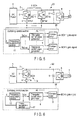
- FIG. 1 is a block diagram representing a schematic configuration of the first embodiment of an electric-vehicle driving apparatus according to the invention.
- a main circuit 25 will be described first.
- a DC power supply 1 is a combination of an engine power generators on a vehicle plus a rectifier, or an AC electric train line (aerial line) plus a converter.
- the DC power supply 1 is connected through a first switch 2 to plural power-generation brake circuits 19, a filter capacitor 5, and an inverter 6.
- the inverter 6 is connected to a motor 7 which functions as a power source for driving the electric vehicle.
- a total N of power-generation brake circuits 19 each are connected in parallel to two ends of the filter capacitor 5.
- the power-generation brake circuits 19 each are constituted as a serial circuit comprising a brake-chopper switching circuit 3 for controlling regenerative power, and a resistor 4 (hereinafter referred to as a brake resistor) for consuming electric power which is caused to flow by switching operation.
- each inverter is provided with plural brake-chopper switching circuits.
- the switching control section 26 for the brake-chopper switching circuits 3 controls conduction states (on/off) of switching elements used in the switching circuits 3.
- the switching control section 26 is input with the number N of the brake-chopper switching circuits.
- a phase calculation section 8 provided in the switching control section 26 is input with the number N of brake-chopper switching circuits 3, and calculates triangular carrier waves of the respective brake-chopper switching circuits.
- the phase calculation section 8 calculates a phase ⁇ BCH of a triangular carrier wave in a manner expressed by an expression 1 below.
- Math 1 ⁇ BCHn ⁇ 2 * ⁇ * fBCH ⁇ dt + n - 1 * 2 ⁇ ⁇ / N
- FIG. 2 is a graph representing the phases ⁇ BCHn of triangular carrier waves which are calculated by the phase calculation section 8.
- Each of the phases ⁇ BCHn increases in proportion to time t, and a phase difference between adjacent two phases ⁇ BCHn and ⁇ BCHn+1 is 2 ⁇ /N.
- Outputs ⁇ BCH1 to ⁇ BCHN are input to triangular carrier wave generators 9 for the respective brake-chopper switching circuits 3.
- the triangular carrier wave generators 9 generate triangular carrier waves respectively for the brake-chopper switching circuits 3, in correspondence with the phases ⁇ BCHn.
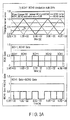
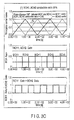
- FIGS. 3 represent a triangular carrier wave and a conduction ratio AL when the power-generation brake circuit 19 is constituted by two circuits (BCH1 and BCH2: upper graph), gate signals which are output from the comparator 10 (BCH1Gate and BCH2Gate: middle graph), and a composite signal of the gate signals (BCH1Gate + BCH2Gate: lower graph).
- the conduction ratios AL are 25 % in FIG. 3A , 50 % in FIG. 3B , and 75 % in FIG. 3C .
- triangle waves respectively generated by the two circuits have phases shifted by 180° from each other.
- the switching element of the brake-chopper switching circuit 3 When the conduction ratio AL is greater than a triangular carrier wave, the switching element of the brake-chopper switching circuit 3 turns on. When the conduction ratio AL is smaller than a triangular carrier wave, the switching element turns off, Accordingly, a demodulation control is performed on a pulse width for switching.
- FIG. 4 shows simulation results of harmonic waves which are generated by switching of the brake-chopper switching circuits to which the present embodiment is applied.
- a waveform 111 represents a harmonic spectrum waveform when one inverter is used
- a waveform 112 represents a harmonic spectrum waveform when a string of four engine vehicles (including eight inverter circuits) was used.
- the switching frequency fBCH of the switching circuits is 327 Hz
- a rotation frequency (FR) of motors is 27.8 Hz.
- a harmonic component generated by the inverters is 654 Hz which is just twice the harmonic wave frequency 327 Hz generated by the brake-chopper switching circuits.
- a secondary harmonic component 114 of the switching frequency fBCH and a harmonic component generated by inverters are superposed on each other to remarkably increase amplitudes of ripples, compared with inverters which operate at a different frequency.
- phases of triangular carrier waves for generating switching signals for the respective brake-chopper switching circuits 3 are shifted from one another, in accordance with the number of brake-chopper switching circuits 3. Therefore, amplitudes of frequency spectra of ripples of output currents from the brake-chopper switching circuits 3 could be reduced more than in conventional cases in which the power-generation brake circuit 19 was constituted by one circuit.
- harmonic waves which were generated by interference between harmonic components generated by the brake-chopper switching circuits 3 and by inverters could be reduced as well. Accordingly, harmonic components generated by the brake-chopper switching circuits 3 can be suppressed, and performance of the electric-vehicle driving apparatus can be improved.
- FIG. 5 is a block diagram representing a schematic configuration of the second embodiment of an electric-vehicle driving apparatus according to the invention.
- a main circuit 26 has the same configuration as in the first embodiment.
- brake-chopper switching circuits in a switching control section 26 are supplied with triangular carrier waves at different frequencies, respectively.
- a frequency calculation section 11 provided in the switching control section 26 is input with a number N of brake-chopper switching circuits 3, and calculates frequencies of the triangular carrier waves for the respective brake-chopper switching circuits 3. For example, a frequency fBCH of a triangular carrier wave is determined in a manner expressed by an expression (2) below.
- fBCHn f ⁇ 0 + n - 1 * ⁇ f
- N is a number of brake-chopper switching circuits 3 connected in parallel. Therefore, triangular carrier wave frequencies fBCH to fBCHN are all different from each other, and an n-th triangular carrier wave frequency fBCH and an (n+1)-th triangular carrier wave frequency fBCHn+1 differ by f0 from each other.
- FSCH1 to fBCHN are predetermined values.
- the triangular carrier wave frequencies fBCH1 to fBCHN are all different from each other.
- the output signals fBCH1 to fBCHN are respectively input to triangular carrier wave generators 9.
- a triangular carrier wave is generated for each of the brake-chopper switching circuit 3.
- the output triangular carrier waves from the triangular carrier wave generators 9 are input to a comparator 10, and the switching elements 3 are controlled to switch on/off by comparison with a conduction ratio AL as in the first embodiment.
- the triangular carrier wave frequencies of the brake-chopper switching circuits 3 are determined depending on the number of brake-chopper switching circuits 3. Therefore, frequency spectra of ripples occurring in output currents of the brake-chopper switching circuits 3 are dispersed so that amplitudes of ripple components are decreased. Further, harmonic waves generated by interference between harmonic components generated by the brake-chopper switching circuits 3 and by inverters are decreased as well. Accordingly, harmonic components generated by the brake-chopper switching circuits 3 can be suppressed, and performance of the electric-vehicle driving apparatus can be improved.
- FIG. 6 is a block diagram representing a schematic configuration of the third embodiment of an electric-vehicle driving apparatus according to the invention.
- a main circuit 25 is provided with one power-generation brake circuit 19 for each inverter circuit.
- a switching control section 26 comprises a frequency calculation section 12, a triangular carrier wave generator 9, a phase estimation section 27, and a comparator 10.
- the phase estimation section 27 is input with a carrier-triangle-wave frequency fBCH from the frequency calculation section 12, and calculates a phase ⁇ (0° to 360°) on the basis of an expression (4) below.
- Math 2 ⁇ ⁇ 2 * ⁇ * fBCH ⁇ dt
- the frequency calculation section 12 calculates a carrier frequency fBCH of the basis of the phase ⁇ input from the phase estimation section 27.
- the triangular carrier wave generator 9 generates a triangular carrier wave for the brake-chopper switching circuit 3 in accordance with the triangular carrier wave frequency fBCH.
- the comparator 10 outputs a gate signal for the switching circuit 3 by comparison between the triangular carrier wave output from the triangular carrier wave generator 9 and a conduction ratio AL.
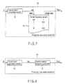
- FIG. 7 is a diagram representing a configuration example of the frequency calculation section 12.
- a carrier-count calculation section 13 is input with a phase ⁇ of a triangular carrier wave, counts a number of triangle waves by a counter of base-M numeral system, and outputs a triangular carrier wave count value NM.
- NM floor ⁇ deg / 360 deg
- floor() is a function which discards decimals from the numerical value in the parenthesis.
- a carrier frequency pattern table 14 prestores M carrier frequencies corresponding to the carrier-wave count value NM.
- the carrier wave pattern table 14 takes the carrier count value NM as an address, and outputs corresponding carrier frequency data as a carrier frequency fBCHn at the present time point. Therefore, the frequency calculation section 12 outputs a carrier frequency which cyclically changes.
- the phase estimation section 27 outputs a phase (0° to 360°) on the bases of each carrier frequency fECHn supplied from the frequency calculation section 12. Based on a phase supplied from the phase estimation section 27, a carrier-count calculation section 13 in the frequency calculation section 12 counts cycles of the phase, and outputs a count value as MM.
- the frequency calculation section 12 outputs a carrier frequency fBCHn corresponding to the count value NM by using the carrier frequency pattern table 14.
- the carrier frequency generator 9 outputs a triangular carrier wave having a cycle which differs for each wave of the triangle wave.
- the brake-chopper-switching control section 26 configured as described above calculates in advance carrier frequencies fBCHn corresponding to the triangular carrier wave phase ⁇ and values (referred to as a carrier count value in this embodiment) depending on the phase, and prestores the carrier frequencies fBCHn into a table. During operation (during braking), the table is referred to.
- frequency spectra of ripples of an output current of the brake-chopper switching circuit 3 is dispersed by cyclically changing the carrier frequency (along time) into predetermined values. Therefore, harmonic components generated by the brake-chopper switching circuit 3 can be suppressed, and an electric-vehicle driving apparatus with improved performance can be provided.
- use of predetermined carrier frequencies facilitates reproducibility analysis for estimations, evaluations, and faults.
- FIG. 8 is a diagram representing another configuration example of the frequency calculation section 12. This frequency calculation section 12 outputs carrier frequencies by a random method.
- the carrier-count calculation section 13 is input with the phase ⁇ of a triangular carrier wave and outputs a carrier count value NM, as described above.
- a random carrier frequency generator 16 generates and outputs a carrier frequency fBCHn which randomly changes without regularity, in accordance with the carrier count value NM generated by the carrier-count calculation section 13.
- the brake-chopper switching circuit 3 configured as described above can uniformly dispense output current harmonic waves of the brake-chopper switching circuit 3 by randomly changing the carrier frequency. As a result, a feature of generating no particular frequency components, which is a purpose of dispersing the carrier frequency, can appear more conspicuous. Accordingly, an electric-vehicle driving apparatus with improved performance can be provided.
- FIG. 9 is a block diagram representing a schematic configuration of the fourth embodiment of an electric-vehicle driving apparatus according to the invention.
- a main circuit 25 of the electric-vehicle driving apparatus according to the fourth embodiment is provided with an open switch 17 between each of brake-chopper switching circuits 3 and a positive electrode of a DC power supply 1.
- Each of the brake-chopper switching circuits 3 is provided with a fault detection section 24.
- a control section (unillustrated) of the electric-vehicle driving apparatus opens the open switch 17 connected to a corresponding brake-chopper switching circuit 3, and cuts off flow of a large current when the fault occurs. Therefore, the other properly working brake-chopper switching circuits 3 and inverter device 6 are prevented from being damaged. Accordingly, an electric-vehicle driving apparatus which ensures redundancy of the system can be provided.
- FIG. 10 is a block diagram representing a schematic configuration of the fifth embodiment of an electric-vehicle driving apparatus according to the invention.
- a main circuit 26 has the same configuration as in the first embodiment.
- a circuit-number calculation section 29 is provided before a phase calculation section 8, in a switching control section 26.
- N is a total number of brake-chopper switching circuits
- NF is a number of problematic brake-chopper switching circuits.
- the phase calculation section 8 determines phases ⁇ BCH of triangular carrier waves as in the first embodiment, in accordance with the revised calculated number of brake-chopper switching circuits 3.
- the problematic brake-chopper switching circuit 3 when a brake-chopper switching circuit 3 causes a fault of short-circuiting, the problematic brake-chopper switching circuit 3 can be separated by opening an open switch connected to the problematic brake-chopper switching circuit 3. The remaining properly working brake-chopper switching circuits 3 can be made continue operating. In addition, carrier phases of the properly working brake-chopper switching circuits 3 can be shifted in accordance with the number N* of the properly working circuits 3, and harmonic waves generated by the brake-chopper switching circuits 3 can be thereby reduced. Therefore, an electric-vehicle driving apparatus which ensures redundancy and performance can be provided.
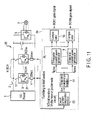
- FIG. 11 is a block diagram representing a schematic configuration of the sixth embodiment of an electric-vehicle driving apparatus according to the invention.
- a main circuit 26 has the same configuration as that of the fifth embodiment in FIG. 10 .
- a switching control section 26 is provided with a frequency calculation section 11 in place of a phase calculation section 8 in FIG. 10 .
- a control section (unillustrated) of the electric-vehicle driving apparatus When a part of fault detection sections 24 of plural brake-chopper switching circuits 3 detects a fault of short-circuiting, a control section (unillustrated) of the electric-vehicle driving apparatus firstly separates a problematic brake-chopper switching circuit 3 causing the fault, by opening an open switch 17 connected to the problematic brake-chopper switching circuit 3, and keeps the remaining properly working brake-chopper switching circuits 3 operating. At this time, the circuit-number calculation section 29 calculates a number N* of the properly working brake-chopper switching circuits 3, as in the fifth embodiment, and outputs the number N* to a frequency calculation section 11.
- the frequency calculation section 11 determines frequencies fBCH of triangular carrier waves in accordance with the number N* of properly working brake-chopper switching circuits 3, as in the second embodiment.
- the problematic brake-chopper switching circuit 3 when a brake-chopper switching circuit 3 causes a fault of short-circuiting, the problematic brake-chopper switching circuit 3 can be separated by opening an opening switch. The remaining properly working brake-chopper switching circuits 3 can be made continue operating.
- carrier phases of the properly working brake-chopper switching circuits 3 are changed in accordance with the number N* of the properly working circuits 3, thereby to reduce harmonic waves generated by the brake-chopper switching circuits 3. Therefore, an electric-vehicle driving apparatus which ensures redundancy and performance can be provided.
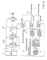
- FIG. 12 is a block diagram representing a schematic configuration of the seventh embodiment of an electric-vehicle driving apparatus according to the invention.
- a voltage detector 30 which detects a capacitor voltage EFC of a filter capacitor 5
- a voltage comparator 20 which compares the capacitor voltage EFC with an overvoltage definition value Vovd
- a switch 21 which switches outputs of comparators 10 in accordance with a comparison result of the comparator 10.
- a switch 21 supplies outputs of the comparators 10 as gate signals of brake-chopper switching circuits 3, as in conventional cases.
- the switch 21 maintains all gates of the brake-chopper switching circuits 3 switched on, independently from the outputs of the comparator 10.
- FIGS. 13 sand 14 are block diagrams representing schematic configurations of the eighth embodiment of an electric-vehicle driving apparatus according to the invention.
- K electric vehicle control devices each of which is the same as that in the first embodiment are connected in parallel to two ends of a DC power supply 1.
- Two configurations described below are provided in which reactors are respectively arranged in different layouts.
- K DC power supplies connected in parallel are connected to an electric vehicle control device through one single reactor 18, as represented in FIG. 13 .
- the K electric vehicle control devices are connected in parallel to an intermediate link.
- the present embodiment is applied to a vehicle of a type in which plural (K) inverters are mounted on one single vehicle.
- K electric vehicle control devices each of which comprises a reactor 18 are connected in parallel to a DC power supply 1, as represented in FIG. 14 .
- This configuration example is applied to a case of operating a string of electric motor vehicles, or to a so-called electric train constituted by a string of two or more vehicles (wherein each of the vehicles is provide with an inverter circuit).
- a switching control section 26 in each of the electric vehicle control devices is input with a total number K and an location number Km of its own device or vehicle.
- a phase calculation section 22 calculates phases of triangular carrier waves for brake-chopper switching circuits 3, in accordance with the total number K, the location number Km, and the number N of brake-chopper switching circuits, and outputs the phases to triangular carrier wave generators 9, respectively.
- a phase ⁇ BCH of a triangular carrier wave is determined by an expression (6) below.
- Math 3 ⁇ BCHn ⁇ 2 * ⁇ * fBCH dt + n - 1 * 2 ⁇ ⁇ / N + km - 1 * 2 ⁇ ⁇ / K + N
- fBCH is a carrier frequency
- N is the number of brake-chopper switching circuits 3 connected in parallel
- K is a total number of power converters connected in parallel in an input side
- phases of triangular carrier waves for the respective brake-chopper switching circuits 3 are shifted from one another, in accordance with the number K of combined electric vehicle control devices and the number n of brake-chopper switching circuits 3. Therefore, amplitudes of frequency spectra of ripples of output currents from the brake-chopper switching circuits 3 could be decreased.
- harmonic waves which are generated by interference between harmonic components generated by the brake-chopper switching circuits 3 and by inverters could be more reduced. Therefore, performance of the electric-vehicle driving apparatus can be improved. Effects as described above can be achieved even when each of the main circuits 26 is configured to comprise a brake-chopper switching circuit 3 in the present embodiment.
- FIGS. 15 and 16 are block diagrams representing schematic configurations of the ninth embodiment of an electric-vehicle driving apparatus according to the invention.
- Each of main circuits 26 has the same configuration as that in the eighth embodiment.
- each electric vehicle control device is input with a total number K and an own location number Km in the ninth embodiment as well.
- a frequency calculation section 23 calculates frequencies of triangular carrier waves for brake-chopper switching circuits 3, in accordance with the total number K of electric vehicle control devices, the location number Km, and a number N of brake-chopper switching circuits. For example, a frequency fBCH of a triangular carrier wave is determined as expressed by an expression below.
- fBCHn f ⁇ 0 + n - 1 * ⁇ f + kn - 1 * ⁇ f ⁇
- ⁇ f and ⁇ f' are predetermined increases in carrier frequency
- N is a number of brake-chopper switching circuits 3 connected in parallel
- fBCH11 to fBCHKN are predetermined values.
Landscapes
- Engineering & Computer Science (AREA)
- Power Engineering (AREA)
- Transportation (AREA)
- Mechanical Engineering (AREA)
- Life Sciences & Earth Sciences (AREA)
- Sustainable Development (AREA)
- Sustainable Energy (AREA)
- Electric Propulsion And Braking For Vehicles (AREA)
- Control Of Ac Motors In General (AREA)
- Inverter Devices (AREA)
Abstract
Description
- The present invention relates to an electric-vehicle driving apparatus which consumes excessive energy generated while a regenerative brake is operating.
- Driving apparatuses mused in electric vehicles for railways have an operation mode called dynamic braking in which regenerative energy generated by a motor for driving wheels is consumed by brake resistance when a brake is activated. In this mode, a conduction ratio calculated on the basis of a filter capacitor voltage in a side of a direct-current voltage input of an inverter for driving the motor is compared with a brake-chopper triangular carrier wave. Based on a comparison result thereof, a gate signal for a brake-chopper switching circuit is generated thereby to control conduction conditions.
- Harmonic components which are generated when such a brake-chopper switching circuit operates sometimes cause inductive interference with an electric generator system. As relevant prior art techniques to reduction of harmonic components, Jpn. Pat. Appln. KOKAI Publications No.
9-140165 2006-67638 - In a conventional vehicle system, a brake-chopper switching circuit uses a constant carrier frequency, and therefore generates harmonic components at a particular frequency.
FIG. 17 shows simulation results concerning harmonic components generated by switching of a conventional brake-chopper switching circuit. A power generation system is under limitations of limit values to harmonic components for various signal systems, for example, because communications are established by using rails. Acurve 100 denotes such a limitation value. Awaveform 111 represents a spectrum waveform of a harmonic wave which was generated from a brake-chopper switching circuit when one inverter circuit is used. Awaveform 112 represents a spectrum waveform of a harmonic wave which was generated from the brake-chopper switching circuit when a string of four engine vehicles (including eight inverter circuits) was used. In this example, the brake-chopper switching circuit has a switching frequency fBCH of 327 Hz, and a motor rotation frequency was 8.6 Hz. - At the switching frequency fBCH, a
ripple 113 occurred and suggests a high-frequency component which was generated by switching the brake-chopper switching circuit.Ripples ripple 113 of a high-frequency wave which was generated by the brake-chopper switching circuit was small (i.e., a margin value from a ripple peak to a most strict limitation value). - Although the switching frequency fBCH of the brake-chopper switching circuit is constant, a frequency of ripples generated by an inverter varies in proportion to a vehicle speed. Accordingly, a harmonic component of a particular frequency fBCH and a harmonic component, which is generated by superposing with a harmonic component generated from an inverter, may cause inductive interference with communication channels of a power generation system.
- The present invention has an object of providing an electric-vehicle driving apparatus in which regenerative energy is consumed by a brake resistor, the apparatus being capable of reducing harmonic components generated by brake-chopper switching circuits in an electric-vehicle driving apparatus.
- In an embodiment of the invention, plural brake-chopper switching circuits are provided in an electric-vehicle driving apparatus in which regenerative energy is consumed by a brake resistor. Harmonic components generated by the brake-chopper switching circuits are reduced by changing phases or frequencies of triangular carrier waves of the respective switching circuits, As a result, stable communications can be performed through a power generation system (rails).
-
-
FIG. 1 is a block diagram representing a configuration of the first embodiment of the invention; -
FIG. 2 is a graph representing phases θBCHn of triangular carrier waves calculated by aphase calculation section 8; -
FIG. 3A represents relationships between a triangular carrier wave and a conduction ratio AL (upper graph), gate signals output from a comparator 10 (middle graph), and a composite signal of the gate signals (lower graph): -
FIG. 3B represents relationships between a triangular carrier wave and another conduction ratio AL (upper graph), gate signals output from the comparator 10 (middle graph), and a composite signal of the gate signals (lower graph); -
FIG. 3C represents relationships between a triangular carrier wave and still another conduction ratio AL (upper graph), gate signals output from the comparator 10 (middle graph), and a composite signal of the gate signals (lower graph); -
FIG. 4 is a graph showing simulation results of harmonic waves of brake-chopper switching circuits to which the first embodiment is applied; -
FIG. 5 is a block diagram representing a configuration of the second embodiment of the invention; -
FIG. 6 is a block diagram representing a configuration of the third embodiment of the invention; -
FIG. 7 is a block diagram representing a configuration of afrequency calculation section 12; -
FIG. 8 is a block diagram representing another configuration of thefrequency calculation section 12; -
FIG. 9 is a block diagram representing a configuration of the fourth embodiment of the invention; -
FIG. 10 is a block diagram representing a configuration of the fifth embodiment of the invention; -
FIG. 11 is a block diagram representing a configuration of the sixth embodiment of the invention; -
FIG. 12 is a block diagram representing a configuration of the seventh embodiment of the invention; -
FIG. 13 is a block diagram representing a configuration of the eighth embodiment of the invention; -
FIG. 14 is a block diagram representing another configuration of the eighth embodiment of the invention; -
FIG. 15 is a block diagram representing a configuration of the ninth embodiment of the invention; -
FIG. 16 is a block diagram representing another configuration of the ninth embodiment of the invention; and -
FIG. 17 is a graph showing simulation results of harmonic waves of a conventional brake-chopper switching circuit. - Hereinafter, embodiments of the invention will be described with reference to the drawings.
-
FIG. 1 is a block diagram representing a schematic configuration of the first embodiment of an electric-vehicle driving apparatus according to the invention. - A
main circuit 25 will be described first. ADC power supply 1 is a combination of an engine power generators on a vehicle plus a rectifier, or an AC electric train line (aerial line) plus a converter. TheDC power supply 1 is connected through afirst switch 2 to plural power-generation brake circuits 19, afilter capacitor 5, and aninverter 6. Theinverter 6 is connected to amotor 7 which functions as a power source for driving the electric vehicle. - For example, a total N of power-
generation brake circuits 19 each are connected in parallel to two ends of thefilter capacitor 5. The power-generation brake circuits 19 each are constituted as a serial circuit comprising a brake-chopper switching circuit 3 for controlling regenerative power, and a resistor 4 (hereinafter referred to as a brake resistor) for consuming electric power which is caused to flow by switching operation. Thus, in the electric-vehicle driving apparatus according to the present embodiment, each inverter is provided with plural brake-chopper switching circuits. - Next, a
switching control section 26 will be described. Theswitching control section 26 for the brake-chopper switching circuits 3 controls conduction states (on/off) of switching elements used in theswitching circuits 3. The switchingcontrol section 26 is input with the number N of the brake-chopper switching circuits. - A
phase calculation section 8 provided in the switchingcontrol section 26 is input with the number N of brake-chopper switching circuits 3, and calculates triangular carrier waves of the respective brake-chopper switching circuits. - For example, the
phase calculation section 8 calculates a phase θBCH of a triangular carrier wave in a manner expressed by anexpression 1 below.
- Here, fBCH expresses a triangular carrier wave frequency of the brake-
chopper switching circuits 3, N expresses a number of the brake-chopper switching circuits 3 connected in parallel, and n expresses an n-th brake-chopper switching circuit (where n = 1 to N).FIG. 2 is a graph representing the phases θBCHn of triangular carrier waves which are calculated by thephase calculation section 8. Each of the phases θBCHn increases in proportion to time t, and a phase difference between adjacent two phases θBCHn and θBCHn+1 is 2π/N. - Outputs θBCH1 to θBCHN are input to triangular
carrier wave generators 9 for the respective brake-chopper switching circuits 3. The triangularcarrier wave generators 9 generate triangular carrier waves respectively for the brake-chopper switching circuits 3, in correspondence with the phases θBCHn. - A
comparator 10 is input with the output triangular carrier waves from the triangularcarrier wave generators 9, and conduction ratios AL of the brake-chopper switching circuits 3 which are calculated by a momentary voltage at thefilter capacitor 5.FIGS. 3 represent a triangular carrier wave and a conduction ratio AL when the power-generation brake circuit 19 is constituted by two circuits (BCH1 and BCH2: upper graph), gate signals which are output from the comparator 10 (BCH1Gate and BCH2Gate: middle graph), and a composite signal of the gate signals (BCH1Gate + BCH2Gate: lower graph). The conduction ratios AL are 25 % inFIG. 3A , 50 % inFIG. 3B , and 75 % inFIG. 3C . As represented in the upper graph ofFIG. 3A , when the power-generation brake circuit 19 is constituted by two circuits, triangle waves respectively generated by the two circuits have phases shifted by 180° from each other. - When the conduction ratio AL is greater than a triangular carrier wave, the switching element of the brake-
chopper switching circuit 3 turns on. When the conduction ratio AL is smaller than a triangular carrier wave, the switching element turns off, Accordingly, a demodulation control is performed on a pulse width for switching. Thus, for example, when two power-generation brake circuits 19 are provided, ripple components generated by their own btake-chopper switching circuits 3 have phases which are inverse to each other (phase difference = π), and therefore logically cancel each other. -
FIG. 4 shows simulation results of harmonic waves which are generated by switching of the brake-chopper switching circuits to which the present embodiment is applied. Awaveform 111 represents a harmonic spectrum waveform when one inverter is used, and awaveform 112 represents a harmonic spectrum waveform when a string of four engine vehicles (including eight inverter circuits) was used. In this example, the switching frequency fBCH of the switching circuits is 327 Hz, and a rotation frequency (FR) of motors is 27.8 Hz. Further, a harmonic component generated by the inverters is 654 Hz which is just twice the harmonic wave frequency 327 Hz generated by the brake-chopper switching circuits. In this case, conventionally, a secondaryharmonic component 114 of the switching frequency fBCH and a harmonic component generated by inverters are superposed on each other to remarkably increase amplitudes of ripples, compared with inverters which operate at a different frequency. - In contrast, as is apparent from
FIG. 4 , amplitudes of harmonic components generated by the brake-chopper switching circuits are suppressed to low values, according to the invention. All ofripples - As has been described above, according to the present embodiment, phases of triangular carrier waves for generating switching signals for the respective brake-
chopper switching circuits 3 are shifted from one another, in accordance with the number of brake-chopper switching circuits 3. Therefore, amplitudes of frequency spectra of ripples of output currents from the brake-chopper switching circuits 3 could be reduced more than in conventional cases in which the power-generation brake circuit 19 was constituted by one circuit. In addition, harmonic waves which were generated by interference between harmonic components generated by the brake-chopper switching circuits 3 and by inverters could be reduced as well. Accordingly, harmonic components generated by the brake-chopper switching circuits 3 can be suppressed, and performance of the electric-vehicle driving apparatus can be improved. -
FIG. 5 is a block diagram representing a schematic configuration of the second embodiment of an electric-vehicle driving apparatus according to the invention. - A
main circuit 26 has the same configuration as in the first embodiment. In the second embodiment, brake-chopper switching circuits in aswitching control section 26 are supplied with triangular carrier waves at different frequencies, respectively. - A
frequency calculation section 11 provided in the switchingcontrol section 26 is input with a number N of brake-chopper switching circuits 3, and calculates frequencies of the triangular carrier waves for the respective brake-chopper switching circuits 3. For example, a frequency fBCH of a triangular carrier wave is determined in a manner expressed by an expression (2) below.
- In the expression, n expresses a total number n of brake-chopper switching circuits 3 (where n = 1 to N). N is a number of brake-
chopper switching circuits 3 connected in parallel. Therefore, triangular carrier wave frequencies fBCH to fBCHN are all different from each other, and an n-th triangular carrier wave frequency fBCH and an (n+1)-th triangular carrier wave frequency fBCHn+1 differ by f0 from each other. - Alternatively, predetermined frequencies are supplied respectively to the brake-
chopper switching circuits 3.
- In the expression, FSCH1 to fBCHN are predetermined values.
- In any of the expressions (2) and (3), the triangular carrier wave frequencies fBCH1 to fBCHN are all different from each other.
- The output signals fBCH1 to fBCHN are respectively input to triangular
carrier wave generators 9. In accordance with the carrier frequency fBCHn, a triangular carrier wave is generated for each of the brake-chopper switching circuit 3. - The output triangular carrier waves from the triangular
carrier wave generators 9 are input to acomparator 10, and theswitching elements 3 are controlled to switch on/off by comparison with a conduction ratio AL as in the first embodiment. - With the configuration as described above, the triangular carrier wave frequencies of the brake-
chopper switching circuits 3 are determined depending on the number of brake-chopper switching circuits 3. Therefore, frequency spectra of ripples occurring in output currents of the brake-chopper switching circuits 3 are dispersed so that amplitudes of ripple components are decreased. Further, harmonic waves generated by interference between harmonic components generated by the brake-chopper switching circuits 3 and by inverters are decreased as well. Accordingly, harmonic components generated by the brake-chopper switching circuits 3 can be suppressed, and performance of the electric-vehicle driving apparatus can be improved. -
FIG. 6 is a block diagram representing a schematic configuration of the third embodiment of an electric-vehicle driving apparatus according to the invention. - A
main circuit 25 is provided with one power-generation brake circuit 19 for each inverter circuit. A switchingcontrol section 26 comprises afrequency calculation section 12, a triangularcarrier wave generator 9, aphase estimation section 27, and acomparator 10. Thephase estimation section 27 is input with a carrier-triangle-wave frequency fBCH from thefrequency calculation section 12, and calculates a phase θ (0° to 360°) on the basis of an expression (4) below.
- The
frequency calculation section 12 calculates a carrier frequency fBCH of the basis of the phase θ input from thephase estimation section 27. The triangularcarrier wave generator 9 generates a triangular carrier wave for the brake-chopper switching circuit 3 in accordance with the triangular carrier wave frequency fBCH. Thecomparator 10 outputs a gate signal for theswitching circuit 3 by comparison between the triangular carrier wave output from the triangularcarrier wave generator 9 and a conduction ratio AL. -
FIG. 7 is a diagram representing a configuration example of thefrequency calculation section 12. A carrier-count calculation section 13 is input with a phase θ of a triangular carrier wave, counts a number of triangle waves by a counter of base-M numeral system, and outputs a triangular carrier wave count value NM.
- In the expression above, "floor()" is a function which discards decimals from the numerical value in the parenthesis.
- A carrier frequency pattern table 14 prestores M carrier frequencies corresponding to the carrier-wave count value NM. The carrier wave pattern table 14 takes the carrier count value NM as an address, and outputs corresponding carrier frequency data as a carrier frequency fBCHn at the present time point. Therefore, the
frequency calculation section 12 outputs a carrier frequency which cyclically changes. - That is, the
phase estimation section 27 outputs a phase (0° to 360°) on the bases of each carrier frequency fECHn supplied from thefrequency calculation section 12. Based on a phase supplied from thephase estimation section 27, a carrier-count calculation section 13 in thefrequency calculation section 12 counts cycles of the phase, and outputs a count value as MM. Thefrequency calculation section 12 outputs a carrier frequency fBCHn corresponding to the count value NM by using the carrier frequency pattern table 14. - The
carrier frequency generator 9 outputs a triangular carrier wave having a cycle which differs for each wave of the triangle wave. - The brake-chopper-switching
control section 26 configured as described above calculates in advance carrier frequencies fBCHn corresponding to the triangular carrier wave phase θ and values (referred to as a carrier count value in this embodiment) depending on the phase, and prestores the carrier frequencies fBCHn into a table. During operation (during braking), the table is referred to. - In the present embodiment, frequency spectra of ripples of an output current of the brake-
chopper switching circuit 3 is dispersed by cyclically changing the carrier frequency (along time) into predetermined values. Therefore, harmonic components generated by the brake-chopper switching circuit 3 can be suppressed, and an electric-vehicle driving apparatus with improved performance can be provided. In addition, use of predetermined carrier frequencies facilitates reproducibility analysis for estimations, evaluations, and faults. -
FIG. 8 is a diagram representing another configuration example of thefrequency calculation section 12. Thisfrequency calculation section 12 outputs carrier frequencies by a random method. - The carrier-
count calculation section 13 is input with the phase θ of a triangular carrier wave and outputs a carrier count value NM, as described above. A randomcarrier frequency generator 16 generates and outputs a carrier frequency fBCHn which randomly changes without regularity, in accordance with the carrier count value NM generated by the carrier-count calculation section 13. - The brake-
chopper switching circuit 3 configured as described above can uniformly dispense output current harmonic waves of the brake-chopper switching circuit 3 by randomly changing the carrier frequency. As a result, a feature of generating no particular frequency components, which is a purpose of dispersing the carrier frequency, can appear more conspicuous. Accordingly, an electric-vehicle driving apparatus with improved performance can be provided. -
FIG. 9 is a block diagram representing a schematic configuration of the fourth embodiment of an electric-vehicle driving apparatus according to the invention. - An entire configuration of the present embodiment is substantially the same as that of the first embodiment. However, a
main circuit 25 of the electric-vehicle driving apparatus according to the fourth embodiment is provided with anopen switch 17 between each of brake-chopper switching circuits 3 and a positive electrode of aDC power supply 1. Each of the brake-chopper switching circuits 3 is provided with afault detection section 24. - In the configuration as described above, when a fault of short-circuiting is detected by the
fault detection section 24, a control section (unillustrated) of the electric-vehicle driving apparatus opens theopen switch 17 connected to a corresponding brake-chopper switching circuit 3, and cuts off flow of a large current when the fault occurs. Therefore, the other properly working brake-chopper switching circuits 3 andinverter device 6 are prevented from being damaged. Accordingly, an electric-vehicle driving apparatus which ensures redundancy of the system can be provided. -
FIG. 10 is a block diagram representing a schematic configuration of the fifth embodiment of an electric-vehicle driving apparatus according to the invention. - A
main circuit 26 has the same configuration as in the first embodiment. In the fifth embodiment, a circuit-number calculation section 29 is provided before aphase calculation section 8, in aswitching control section 26. - When a part of
fault detection sections 24 of plural brake-chopper switching circuits 3 detects a fault of short-circuiting, a control section (unillustrated) of the electric-vehicle driving apparatus firstly separates a problematic brake-chopper switching circuit 3 causing the fault, by opening theopen switch 17 connected to the problematic brake-chopper switching circuit 3, and keeps the remaining properly working brake-chopper switching circuits 3 operating. Therefore, the circuit-number calculation section 29 calculates a number No* of the properly working brake-chopper switching circuits 3, and outputs the number N* to the carrierphase calculation section 8. For example, the number of properly working circuits is calculated by an expression (5) below.
- In the above expression, N is a total number of brake-chopper switching circuits, and NF is a number of problematic brake-chopper switching circuits.
- The
phase calculation section 8 determines phases θBCH of triangular carrier waves as in the first embodiment, in accordance with the revised calculated number of brake-chopper switching circuits 3. - With the configuration described above, when a brake-
chopper switching circuit 3 causes a fault of short-circuiting, the problematic brake-chopper switching circuit 3 can be separated by opening an open switch connected to the problematic brake-chopper switching circuit 3. The remaining properly working brake-chopper switching circuits 3 can be made continue operating. In addition, carrier phases of the properly working brake-chopper switching circuits 3 can be shifted in accordance with the number N* of the properly workingcircuits 3, and harmonic waves generated by the brake-chopper switching circuits 3 can be thereby reduced. Therefore, an electric-vehicle driving apparatus which ensures redundancy and performance can be provided. -
FIG. 11 is a block diagram representing a schematic configuration of the sixth embodiment of an electric-vehicle driving apparatus according to the invention. - A
main circuit 26 has the same configuration as that of the fifth embodiment inFIG. 10 . In the sixth embodiment, a switchingcontrol section 26 is provided with afrequency calculation section 11 in place of aphase calculation section 8 inFIG. 10 . - When a part of
fault detection sections 24 of plural brake-chopper switching circuits 3 detects a fault of short-circuiting, a control section (unillustrated) of the electric-vehicle driving apparatus firstly separates a problematic brake-chopper switching circuit 3 causing the fault, by opening anopen switch 17 connected to the problematic brake-chopper switching circuit 3, and keeps the remaining properly working brake-chopper switching circuits 3 operating. At this time, the circuit-number calculation section 29 calculates a number N* of the properly working brake-chopper switching circuits 3, as in the fifth embodiment, and outputs the number N* to afrequency calculation section 11. - The
frequency calculation section 11 determines frequencies fBCH of triangular carrier waves in accordance with the number N* of properly working brake-chopper switching circuits 3, as in the second embodiment. - With the configuration described above, when a brake-
chopper switching circuit 3 causes a fault of short-circuiting, the problematic brake-chopper switching circuit 3 can be separated by opening an opening switch. The remaining properly working brake-chopper switching circuits 3 can be made continue operating. In addition, carrier phases of the properly working brake-chopper switching circuits 3 are changed in accordance with the number N* of the properly workingcircuits 3, thereby to reduce harmonic waves generated by the brake-chopper switching circuits 3. Therefore, an electric-vehicle driving apparatus which ensures redundancy and performance can be provided. -
FIG. 12 is a block diagram representing a schematic configuration of the seventh embodiment of an electric-vehicle driving apparatus according to the invention. - In the seventh embodiment, there are provided a
voltage detector 30 which detects a capacitor voltage EFC of afilter capacitor 5, avoltage comparator 20 which compares the capacitor voltage EFC with an overvoltage definition value Vovd, and aswitch 21 which switches outputs ofcomparators 10 in accordance with a comparison result of thecomparator 10. - The
voltage comparator 20 determines whether the filter capacitor voltage is excessive or not by comparing the filter capacitor voltage EFC detected by thevoltage detector 30 with the overvoltage definition value Vovd. If the filter capacitor voltage EFC exceeds the overvoltage definition value Vovd, an overvoltage signal OVD = 1 is output. - When the overvoltage signal OVD = 0, a
switch 21 supplies outputs of thecomparators 10 as gate signals of brake-chopper switching circuits 3, as in conventional cases. When the overvoltage signal OVD = 1, theswitch 21 maintains all gates of the brake-chopper switching circuits 3 switched on, independently from the outputs of thecomparator 10. - With the configuration as described above, when a filter capacitor overvoltage occurs, gate signals for all the brake-
chopper switching circuits 3 are changed to ON-continuation signals at once, and the filter capacitor overvoltage is discharged. Therefore, inverter devices can be prevented from being damaged by a filter capacitor overvoltage, and an electric-vehicle driving apparatus which ensures redundancy of the system can be provided. -
FIGS. 13 sand 14 are block diagrams representing schematic configurations of the eighth embodiment of an electric-vehicle driving apparatus according to the invention. - In the eighth embodiment, K electric vehicle control devices each of which is the same as that in the first embodiment are connected in parallel to two ends of a
DC power supply 1. Two configurations described below are provided in which reactors are respectively arranged in different layouts. - In a first configuration example, K DC power supplies connected in parallel are connected to an electric vehicle control device through one
single reactor 18, as represented inFIG. 13 . For example, the K electric vehicle control devices are connected in parallel to an intermediate link. The present embodiment is applied to a vehicle of a type in which plural (K) inverters are mounted on one single vehicle. - In a second configuration example, K electric vehicle control devices each of which comprises a
reactor 18 are connected in parallel to aDC power supply 1, as represented inFIG. 14 . This configuration example is applied to a case of operating a string of electric motor vehicles, or to a so-called electric train constituted by a string of two or more vehicles (wherein each of the vehicles is provide with an inverter circuit). - In the electric vehicle control devices configured as described above, a switching
control section 26 in each of the electric vehicle control devices is input with a total number K and an location number Km of its own device or vehicle. - A
phase calculation section 22 calculates phases of triangular carrier waves for brake-chopper switching circuits 3, in accordance with the total number K, the location number Km, and the number N of brake-chopper switching circuits, and outputs the phases to triangularcarrier wave generators 9, respectively. - For example, a phase θBCH of a triangular carrier wave is determined by an expression (6) below.

- In the expression above, fBCH is a carrier frequency, N is the number of brake-
chopper switching circuits 3 connected in parallel, n denotes an n-th brake-chopper switching circuit (where n = 1 to N), K is a total number of power converters connected in parallel in an input side, and km denotes an m-the power converter (where m = 1 to K). - With the configuration as described above, phases of triangular carrier waves for the respective brake-
chopper switching circuits 3 are shifted from one another, in accordance with the number K of combined electric vehicle control devices and the number n of brake-chopper switching circuits 3. Therefore, amplitudes of frequency spectra of ripples of output currents from the brake-chopper switching circuits 3 could be decreased. In addition, harmonic waves which are generated by interference between harmonic components generated by the brake-chopper switching circuits 3 and by inverters could be more reduced. Therefore, performance of the electric-vehicle driving apparatus can be improved. Effects as described above can be achieved even when each of themain circuits 26 is configured to comprise a brake-chopper switching circuit 3 in the present embodiment. -
FIGS. 15 and16 are block diagrams representing schematic configurations of the ninth embodiment of an electric-vehicle driving apparatus according to the invention. - Each of
main circuits 26 has the same configuration as that in the eighth embodiment. - As in the eighth embodiment, each electric vehicle control device is input with a total number K and an own location number Km in the ninth embodiment as well. A
frequency calculation section 23 calculates frequencies of triangular carrier waves for brake-chopper switching circuits 3, in accordance with the total number K of electric vehicle control devices, the location number Km, and a number N of brake-chopper switching circuits. For example, a frequency fBCH of a triangular carrier wave is determined as expressed by an expression below.
- In the expression above, Δf and Δf' are predetermined increases in carrier frequency, n denotes an n-th brake-chopper switching circuit 3 (where n = 1 to N), N is a number of brake-
chopper switching circuits 3 connected in parallel, and km denotes an m-th power converter (where m = 1 to K). - Alternatively, predetermined frequencies may respectively be supplied to the brake-
chopper switching circuits 3, as described below.
If (n = 1, km = 1), fBCH - fBCH11
If (n = 2, km = 1), fBCH = fBCH12
... If (n = N, km = 1), fBCH = fBCH1N
...
If (n = N, ken = K), fBCH = fBCHKN - In the expression above, fBCH11 to fBCHKN are predetermined values.
- With the configuration as described above, triangular carrier wave frequencies of the respective brake-
chopper switching circuits 3 are varied in correspondence with the number N of brake-chopper switching circuits 3. Therefore, frequency spectra of ripples of output currents from the brake-chopper switching circuits 3 are dispersed, to thereby decrease amplitudes of the ripples. In addition, harmonic waves which were generated by interference between harmonic components generated by the brake-chopper switching circuits 3 and by inverters could be reduced as well. Therefore, harmonic components generated by the brake-chopper switching circuits 3 can be suppressed, and performance of the electric-vehicle driving apparatus can be improved. As in the foregoing eighth embodiment, effects as described above can be achieved even when each of themain circuits 26 is configured to comprise only one brake-chopper switching circuit 3 in the present embodiment. - Descriptions which have been made above to the embodiments of the invention do not limit apparatuses or methods of the invention but allow easy practice of various modifications.
Claims (6)
- An electric-vehicle driving apparatus characterised by comprising:an electric power converter which is connected to a DC power supply and converts a DC power into a three-phase current power at a variable frequency/voltage, to drive an AC motor;a plurality of power-generation brake circuits each of which is connected in parallel to terminals of the electric power converter in a DC side thereof and is constituted by a serial circuit comprising a switching circuit and a resistor, to control consumption of regenerative electric power; anda switching control section which controls switching of the switching circuits by gate signals generated on the basis of comparison between carrier frequency waves generated for the respective switching circuits and a conduction ratio, whereinthe switching control section generates the gate signals by shifting triangular carrier waves of the respective switching circuits.
- The electric-vehicle driving apparatus of claim 1, characterized in that the switching control section generates triangular carrier waves at frequencies different from each other respectively for the switching circuits.
- The electric-vehicle driving apparatus of claim 1, characterized in that the switching control section separates problematic one of the plurality of switching circuits, and controls the switching circuits by using triangle waves having a phase difference between each other in accordance with a number of remaining properly working ones of the plurality of switching circuits.
- The electric-vehicle driving apparatus of claim 2, characterized in that the switching control section separates problematic one of the plurality of switching circuits, and controls the switching circuits by using triangle waves having a phase difference between each other in accordance with a number of remaining properly working ones of the plurality of switching circuits.
- An electric-vehicle driving apparatus characterized by comprising the electric-vehicle driving apparatus of claim 1, which is provided in a plurality, the plurality of the electric-vehicle driving apparatuses being connected in parallel to a DC power supply, wherein triangular carrier waves having phases which are different from each other are generated respectively for the plurality of switching circuits include in the plurality of the electric-vehicle driving apparatuses.
- An electric-vehicle driving apparatus characterized by comprising:an electric power converter which is connected to a DC power supply and converts a DC power into a three-phase current power at a variable frequency/voltage, to drive an AC motor;a power-generation brake circuit which is connected in parallel to terminals of the electric power converter in a DC side thereof and is constituted by a serial circuit comprising a switching circuit and a resistor, to control consumption of regenerative electric power; anda switching control section which controls switching of the switching circuit by a gate signal generated on the basis of comparison between a carrier frequency wave generated for the switching circuit and a conduction ratio, whereinthe switching control section changes a frequency of the triangular carrier wave as time passes.
Applications Claiming Priority (2)
| Application Number | Priority Date | Filing Date | Title |
|---|---|---|---|
| JP2008058459A JP4643670B2 (en) | 2008-03-07 | 2008-03-07 | Electric car drive |
| PCT/JP2009/053986 WO2009110479A1 (en) | 2008-03-07 | 2009-03-03 | Electric vehicle driving device |
Publications (2)
| Publication Number | Publication Date |
|---|---|
| EP2251224A1 true EP2251224A1 (en) | 2010-11-17 |
| EP2251224A4 EP2251224A4 (en) | 2016-11-23 |
Family
ID=41056033
Family Applications (1)
| Application Number | Title | Priority Date | Filing Date |
|---|---|---|---|
| EP09717856.0A Withdrawn EP2251224A4 (en) | 2008-03-07 | 2009-03-03 | DEVICE FOR DRIVING ELECTRIC VEHICLE |
Country Status (6)
| Country | Link |
|---|---|
| US (1) | US7949443B2 (en) |
| EP (1) | EP2251224A4 (en) |
| JP (1) | JP4643670B2 (en) |
| CN (1) | CN101959708B (en) |
| WO (1) | WO2009110479A1 (en) |
| ZA (1) | ZA201006411B (en) |
Cited By (3)
| Publication number | Priority date | Publication date | Assignee | Title |
|---|---|---|---|---|
| WO2013127942A3 (en) * | 2012-02-29 | 2013-11-21 | Siemens Aktiengesellschaft | Rail vehicle brake device |
| US9306392B2 (en) | 2012-03-01 | 2016-04-05 | General Electric Technology Gmbh | Control circuit for excess energy removal in power transmission lines |
| WO2017108046A1 (en) * | 2015-12-22 | 2017-06-29 | Vestas Wind Systems A/S | Power dissipation system and control method for a wind turbine power converter |
Families Citing this family (30)
| Publication number | Priority date | Publication date | Assignee | Title |
|---|---|---|---|---|
| US8456128B2 (en) * | 2007-07-09 | 2013-06-04 | Power Concepts Nz Limited | Multi output inverter |
| JP5334785B2 (en) * | 2009-09-30 | 2013-11-06 | 三菱電機Fa産業機器株式会社 | Non-excitation actuated electromagnetic brake control device and method |
| JP2011101483A (en) * | 2009-11-05 | 2011-05-19 | Mitsubishi Electric Corp | Drive power supply apparatus for vehicles |
| US9467063B2 (en) * | 2010-11-29 | 2016-10-11 | Sunpower Corporation | Technologies for interleaved control of an inverter array |
| SI2737621T1 (en) * | 2011-07-26 | 2022-10-28 | Moog Inc. | Electric motor clamping system |
| CN103121409B (en) * | 2011-11-18 | 2015-04-22 | 北汽福田汽车股份有限公司 | Automobile braking circuit protecting device and automobile braking device provided with the same |
| WO2013088496A1 (en) * | 2011-12-12 | 2013-06-20 | 三菱電機株式会社 | Electric power conversion device |
| US8820248B2 (en) * | 2011-12-19 | 2014-09-02 | Progress Rail Services Corp | Continuously variable dynamic brake for a locomotive |
| CN104395133B (en) * | 2012-06-28 | 2016-08-24 | 三菱电机株式会社 | The control device of AC electric train |
| DE102013006254A1 (en) * | 2013-04-11 | 2014-10-16 | Audi Ag | Voltage release of a high voltage vehicle |
| GB2513568B (en) * | 2013-04-29 | 2015-05-27 | Control Tech Ltd | Electrical circuit synchronisation |
| JPWO2014188535A1 (en) * | 2013-05-22 | 2017-02-23 | 株式会社日立製作所 | Power converter and wind power generation system |
| JP6306294B2 (en) * | 2013-06-28 | 2018-04-04 | 東洋電機製造株式会社 | Regenerative brake device |
| CN104716851A (en) * | 2013-12-17 | 2015-06-17 | 北车大连电力牵引研发中心有限公司 | Converter control method and device |
| CN105730251B (en) * | 2014-12-09 | 2018-08-21 | 株洲南车时代电气股份有限公司 | Over-pressed copped wave energy consumption balance control system applied to train |
| FR3035557B1 (en) * | 2015-04-23 | 2017-05-12 | Labinal Power Systems | SYSTEM AND METHOD FOR DISSIPATING ELECTRICAL ENERGY REGENERATED BY ACTUATORS |
| CN106787968B (en) * | 2016-12-28 | 2019-06-28 | 江苏经纬轨道交通设备有限公司 | Inhibit the electric braking control system and method for bus fluctuation |
| US10523003B2 (en) * | 2017-01-30 | 2019-12-31 | Cummins Enterprise Inc. | Auxiliary power circuit and method of use |
| JP7047844B2 (en) * | 2017-07-31 | 2022-04-05 | 日本電産株式会社 | Power converters, motor modules and electric power steering devices |
| CN108183618B (en) * | 2017-12-12 | 2020-12-11 | 中国船舶工业系统工程研究院 | A modular pedigree high-power marine inverter |
| CN108032734A (en) * | 2017-12-14 | 2018-05-15 | 株洲联诚集团控股股份有限公司 | A kind of auxiliary power supply circuit, dumper power supply circuit and its control method |
| DE102019005019A1 (en) | 2018-07-30 | 2020-01-30 | Sew-Eurodrive Gmbh & Co Kg | Method for operating a drive system and drive system |
| CN110719045B (en) * | 2019-10-29 | 2021-06-01 | 中车长春轨道客车股份有限公司 | Chopping control system of traction inverter |
| DE102021202914B3 (en) * | 2021-03-25 | 2022-06-15 | Volkswagen Aktiengesellschaft | Pulse-controlled inverter arrangement and method for operating a pulse-controlled inverter arrangement |
| DE102022002305A1 (en) | 2021-07-21 | 2023-01-26 | Sew-Eurodrive Gmbh & Co Kg | Method for operating a drive system and drive system for carrying out a method |
| CN114362489B (en) * | 2021-12-24 | 2024-11-29 | 河南嘉晨智能控制股份有限公司 | Noise suppression method for multipath Mos chopping control system |
| CN114301330B (en) * | 2021-12-28 | 2024-07-19 | 苏州汇川控制技术有限公司 | Brake unit control method, system, apparatus, and computer-readable storage medium |
| JP7814960B2 (en) * | 2022-02-03 | 2026-02-17 | 株式会社東芝 | Power Conversion Device |
| CN119232027A (en) * | 2023-06-30 | 2024-12-31 | 广东美的制冷设备有限公司 | Frequency converter control method, storage medium, controller, and air conditioner |
| EP4560910A1 (en) * | 2023-11-24 | 2025-05-28 | Innomotics GmbH | Construction and control method for a modular brake actuator with at least two brake actuator branches |
Family Cites Families (16)
| Publication number | Priority date | Publication date | Assignee | Title |
|---|---|---|---|---|
| JPS61170203A (en) * | 1985-01-23 | 1986-07-31 | Mitsubishi Electric Corp | Controller for electric railcar |
| US4904918A (en) * | 1989-03-13 | 1990-02-27 | General Electric Company | Power conversion system including an improved filter for attenuating harmonics |
| US5283507A (en) * | 1990-12-20 | 1994-02-01 | General Electric Company | Regenerative braking protection for an electrically-propelled traction vehicle |
| US5170105A (en) * | 1991-03-08 | 1992-12-08 | General Electric Company | Method for determining operability of an electrical dynamic braking system |
| JP3357690B2 (en) * | 1992-09-07 | 2002-12-16 | 株式会社東芝 | Dynamic braking control device for linear motor driven electric vehicle. |
| JPH09140165A (en) | 1995-11-16 | 1997-05-27 | Hitachi Ltd | Power converter |
| US6043996A (en) * | 1999-02-03 | 2000-03-28 | General Electric Company | Method and apparatus for reducing monotonic audible noise in a power conversion system |
| JP2001204101A (en) * | 2000-01-19 | 2001-07-27 | Hitachi Ltd | Electric car brake chopper device |
| EP1134878A1 (en) * | 2000-03-13 | 2001-09-19 | Alstom Belgium S.A. | Method and device for reduction of harmonics in power converters |
| US7185591B2 (en) * | 2001-03-27 | 2007-03-06 | General Electric Company | Hybrid energy off highway vehicle propulsion circuit |
| JP2003348833A (en) * | 2002-05-24 | 2003-12-05 | Fujitsu Ten Ltd | Dc power unit |
| JP2004131207A (en) * | 2002-10-08 | 2004-04-30 | Mitsubishi Electric Corp | Elevator braking control device |
| DE10330284A1 (en) * | 2003-07-04 | 2005-02-03 | Siemens Ag | Overvoltage limiter for a traction converter |
| JP3974092B2 (en) * | 2003-07-09 | 2007-09-12 | 株式会社東芝 | Electric vehicle control device |
| JP4537802B2 (en) | 2004-08-24 | 2010-09-08 | 株式会社東芝 | Power converter |
| FI122124B (en) * | 2006-07-04 | 2011-08-31 | Abb Oy | Procedure for controlling brake switch, brake switch and frequency converter |
-
2008
- 2008-03-07 JP JP2008058459A patent/JP4643670B2/en not_active Expired - Fee Related
-
2009
- 2009-03-03 CN CN200980108154XA patent/CN101959708B/en not_active Expired - Fee Related
- 2009-03-03 EP EP09717856.0A patent/EP2251224A4/en not_active Withdrawn
- 2009-03-03 WO PCT/JP2009/053986 patent/WO2009110479A1/en not_active Ceased
-
2010
- 2010-09-07 ZA ZA2010/06411A patent/ZA201006411B/en unknown
- 2010-09-07 US US12/876,838 patent/US7949443B2/en not_active Expired - Fee Related
Non-Patent Citations (1)
| Title |
|---|
| See references of WO2009110479A1 * |
Cited By (5)
| Publication number | Priority date | Publication date | Assignee | Title |
|---|---|---|---|---|
| WO2013127942A3 (en) * | 2012-02-29 | 2013-11-21 | Siemens Aktiengesellschaft | Rail vehicle brake device |
| RU2586943C2 (en) * | 2012-02-29 | 2016-06-10 | Сименс Акциенгезелльшафт | Railway vehicle braking system |
| US9533668B2 (en) | 2012-02-29 | 2017-01-03 | Siemens Aktiengesellschaft | Rail vehicle braking device |
| US9306392B2 (en) | 2012-03-01 | 2016-04-05 | General Electric Technology Gmbh | Control circuit for excess energy removal in power transmission lines |
| WO2017108046A1 (en) * | 2015-12-22 | 2017-06-29 | Vestas Wind Systems A/S | Power dissipation system and control method for a wind turbine power converter |
Also Published As
| Publication number | Publication date |
|---|---|
| EP2251224A4 (en) | 2016-11-23 |
| CN101959708A (en) | 2011-01-26 |
| US7949443B2 (en) | 2011-05-24 |
| US20100332065A1 (en) | 2010-12-30 |
| CN101959708B (en) | 2012-12-19 |
| JP4643670B2 (en) | 2011-03-02 |
| WO2009110479A1 (en) | 2009-09-11 |
| ZA201006411B (en) | 2011-05-25 |
| JP2009219208A (en) | 2009-09-24 |
Similar Documents
| Publication | Publication Date | Title |
|---|---|---|
| US7949443B2 (en) | Electric-vehicle driving apparatus | |
| US7057361B2 (en) | Inverter control device and electric vehicle thereof | |
| EP2763313B1 (en) | Power conversion control device, power conversion control method, electric motor and vehicle drive system | |
| CN101678778B (en) | Apparatus and method for controlling power split circuit and hybrid electric vehicle having same | |
| US20110074326A1 (en) | Electrical motor/generator drive apparatus and method | |
| EP2665170A1 (en) | System and method of parallel converter current sharing | |
| JPH11318086A (en) | Stationary power converter supplied with unlimited voltage | |
| US9142955B2 (en) | Method and system for fault protection | |
| EP1775828B1 (en) | Power converter methods and apparatus for variable speed high power machines | |
| US20210058003A1 (en) | Filter and afe power cell phase control | |
| JP5361350B2 (en) | Electric vehicle power converter | |
| DE102017213775A1 (en) | Inverter control device and inverter control method | |
| EP3324527B1 (en) | Dc bus ripple elimination for multiphase electric machines | |
| GB2441359A (en) | Control methods for pulse width modulation | |
| JP2003070160A (en) | DC equipment and vehicles using the same | |
| EP1885055A1 (en) | Controller of variable speed ac motor | |
| US11469685B2 (en) | Filter and AFE power cell phase control | |
| JP2018046714A (en) | Motor-driving apparatus | |
| JP2019201444A (en) | Inverter controller and inverter control method | |
| EP4170895A1 (en) | Control device for ac rotating electric machine, and electric power steering device | |
| JP2783204B2 (en) | Control method of PWM converter | |
| Gandomi et al. | A fault tolerant T-type inverter for five-phase PMSM drives | |
| JP4838031B2 (en) | Multiple inverter control system | |
| Sato et al. | Modulation Strategies to Reduce DC Capacitor Current in Two-Motor Drive Systems | |
| CN109391205B (en) | Electric drives and electric equipment |
Legal Events
| Date | Code | Title | Description |
|---|---|---|---|
| PUAI | Public reference made under article 153(3) epc to a published international application that has entered the european phase |
Free format text: ORIGINAL CODE: 0009012 |
|
| 17P | Request for examination filed |
Effective date: 20100906 |
|
| AK | Designated contracting states |
Kind code of ref document: A1 Designated state(s): AT BE BG CH CY CZ DE DK EE ES FI FR GB GR HR HU IE IS IT LI LT LU LV MC MK MT NL NO PL PT RO SE SI SK TR |
|
| AX | Request for extension of the european patent |
Extension state: AL BA RS |
|
| DAX | Request for extension of the european patent (deleted) | ||
| RA4 | Supplementary search report drawn up and despatched (corrected) |
Effective date: 20161026 |
|
| RIC1 | Information provided on ipc code assigned before grant |
Ipc: B60L 9/16 20060101ALI20161017BHEP Ipc: H02M 7/48 20070101ALI20161017BHEP Ipc: B60L 9/18 20060101ALI20161017BHEP Ipc: B60L 7/06 20060101AFI20161017BHEP Ipc: B60L 7/22 20060101ALI20161017BHEP Ipc: B60L 11/08 20060101ALI20161017BHEP Ipc: H02M 7/797 20060101ALI20161017BHEP Ipc: H02P 27/06 20060101ALI20161017BHEP Ipc: B60L 7/16 20060101ALI20161017BHEP |
|
| STAA | Information on the status of an ep patent application or granted ep patent |
Free format text: STATUS: EXAMINATION IS IN PROGRESS |
|
| 17Q | First examination report despatched |
Effective date: 20180131 |
|
| STAA | Information on the status of an ep patent application or granted ep patent |
Free format text: STATUS: THE APPLICATION HAS BEEN WITHDRAWN |
|
| 18W | Application withdrawn |
Effective date: 20180516 |