EP2250651B1 - Electromagnetic actuating mechanism - Google Patents
Electromagnetic actuating mechanism Download PDFInfo
- Publication number
- EP2250651B1 EP2250651B1 EP09718492A EP09718492A EP2250651B1 EP 2250651 B1 EP2250651 B1 EP 2250651B1 EP 09718492 A EP09718492 A EP 09718492A EP 09718492 A EP09718492 A EP 09718492A EP 2250651 B1 EP2250651 B1 EP 2250651B1
- Authority
- EP
- European Patent Office
- Prior art keywords
- permanent magnet
- coils
- actuating
- actuating apparatus
- pole
- Prior art date
- Legal status (The legal status is an assumption and is not a legal conclusion. Google has not performed a legal analysis and makes no representation as to the accuracy of the status listed.)
- Active
Links
Images

Classifications
-
- H—ELECTRICITY
- H01—ELECTRIC ELEMENTS
- H01F—MAGNETS; INDUCTANCES; TRANSFORMERS; SELECTION OF MATERIALS FOR THEIR MAGNETIC PROPERTIES
- H01F7/00—Magnets
- H01F7/06—Electromagnets; Actuators including electromagnets
- H01F7/08—Electromagnets; Actuators including electromagnets with armatures
- H01F7/16—Rectilinearly-movable armatures
- H01F7/1607—Armatures entering the winding
- H01F7/1615—Armatures or stationary parts of magnetic circuit having permanent magnet
-
- H—ELECTRICITY
- H01—ELECTRIC ELEMENTS
- H01F—MAGNETS; INDUCTANCES; TRANSFORMERS; SELECTION OF MATERIALS FOR THEIR MAGNETIC PROPERTIES
- H01F7/00—Magnets
- H01F7/06—Electromagnets; Actuators including electromagnets
- H01F7/08—Electromagnets; Actuators including electromagnets with armatures
- H01F7/16—Rectilinearly-movable armatures
- H01F2007/1661—Electromagnets or actuators with anti-stick disc
-
- H—ELECTRICITY
- H01—ELECTRIC ELEMENTS
- H01F—MAGNETS; INDUCTANCES; TRANSFORMERS; SELECTION OF MATERIALS FOR THEIR MAGNETIC PROPERTIES
- H01F7/00—Magnets
- H01F7/06—Electromagnets; Actuators including electromagnets
- H01F7/08—Electromagnets; Actuators including electromagnets with armatures
- H01F7/16—Rectilinearly-movable armatures
- H01F2007/1692—Electromagnets or actuators with two coils
-
- H—ELECTRICITY
- H01—ELECTRIC ELEMENTS
- H01H—ELECTRIC SWITCHES; RELAYS; SELECTORS; EMERGENCY PROTECTIVE DEVICES
- H01H50/00—Details of electromagnetic relays
- H01H50/16—Magnetic circuit arrangements
- H01H50/163—Details concerning air-gaps, e.g. anti-remanence, damping, anti-corrosion
-
- H—ELECTRICITY
- H01—ELECTRIC ELEMENTS
- H01H—ELECTRIC SWITCHES; RELAYS; SELECTORS; EMERGENCY PROTECTIVE DEVICES
- H01H51/00—Electromagnetic relays
- H01H51/22—Polarised relays
- H01H51/2209—Polarised relays with rectilinearly movable armature
Definitions
- the invention relates to an electromagnetic actuator according to the preamble of claim 1.
- Electromagnetic actuators also called actuators or actuators, servo motors or solenoids, are known in control engineering. For example, they are used to drive or adjust valves or valves for flow control of gaseous or liquid media. Most electromagnetic actuators are bistable, i. H. they have only two stable positions, z. B. open or close.
- a bistable actuator which has two coils and an armature formed as a permanent magnet, arranged on an anchor rod.
- the permanent magnet has a polarity oriented in the displacement direction of the armature and is held by the coils either in one or in the other end position.
- the coil assembly forms a two-terminal, whereby the permanent magnet is attracted by a coil and repelled simultaneously from the other coil and vice versa. This shortens the switching time.
- the Elektrohubmagnet has a total of four coils, two stationary permanent magnets, two outer housing opposite poles, two inner housing opposite poles and two on one Push rod longitudinally movably arranged anchor. An end position is achieved in each case by energizing an outer coil by the armature is attracted by the energized coil. The middle position of the push rod is, however, achieved by the permanently magnetically held anchor by these rest on both sides of the inner housing opposite poles (partition).
- a disadvantage of the known Elektrohubmagnet are the large number of parts, eg. B. four coils, two permanent magnets and two anchors and the associated additional weight.
- the two coils are each at the ends of a pole tube, d. H. a tube of magnetic material and each have a yoke, preferably made of a ferromagnetic material.
- the magnetic flux is passed through the yoke and pole tube, so that depending on the energization of the coil, a different polarity can be formed.
- control rod is arranged coaxially to the pole tube and slidably mounted within openings of the yokes.
- the permanent magnet is assigned a preferably ring-shaped holding pole, which preferably within the pole tube and approximately in the Middle is arranged between the two coils.
- the holding pole is made of a magnetic material and is - flooded by the magnetic flux of the permanent magnet - in the third detent position, ie the center position of the armature.
- the magnetic connection between the holding pole and the permanent magnet results in a magnetic locking of the actuator with currentless coils.
- preferably conical plunger anchors are provided on the end faces of the permanent magnet, which dip into corresponding openings in the coil yoke. This increases the magnetic attraction of the coils on the actuator.
- the polarity of the permanent magnet is aligned in the direction of displacement of the actuator and the control rod.
- a north pole is formed on one end face and a south pole is formed on the opposite end face of the permanent magnet.
- a further coil in the region of the holding pole, a further coil, a so-called center coil, can be arranged which, with appropriate energization, cancels the arresting effect of the permanent magnet in its middle position and thus permits a faster adjustment of the actuator into one or the other end position. This improves the dynamics of the actuator.
- Fig. 1 shows an electromagnetic actuator 1, also called electrodynamic actuator or actuator.
- the actuator 1 has a cylindrical, magnetic pole tube 2, in which two coils 3, 4, each with a yoke 5, 6 are arranged at its ends.
- the coils 3, 4 are connected to a power supply, not shown, and can be energized in different current directions, so that opposite polarities can be formed.
- a disc-shaped permanent magnet 8 is arranged and fixedly connected to the control rod.
- flux guide plates 9, 10 are arranged, which reinforce the permanent magnet flux.
- each anti-sling discs 11, 12 or a liability to the yokes 5, 6 preventing coating On the outside of the flux guide plates 9, 10 are each anti-sling discs 11, 12 or a liability to the yokes 5, 6 preventing coating arranged. Further, each end face on the permanent magnet 8 and on the anchor rod 7 conically shaped plunger 13, 14 are arranged and fixed.
- the adjusting or anchor rod 7, the permanent magnet 8 in conjunction with the Flussleitblechen 9, 10, the anti-adhesive discs 11, 12 and the plunger anchors 13, 14 form the actuator 15 of the actuator or the actuator 1.
- the actuator 15 in its middle position, ie in the middle between the two coils 3, 4 shown.
- an annular holding pole 16 is arranged within the pole tube 2, which surrounds the circumference of the permanent magnet 8.
- the annular holding pole 16 has a smaller inner diameter than the pole tube 2, ie, the holding pole 16 forms a radial narrowing of the pole tube 2.
- the permanent magnet 8 forms over the flux guide plates 9, 10 with the holding pole made of a magnetic material 16 a magnetic circuit, that is, the permanent magnet 8 and with it the adjusting rod 7 are held in the position shown by the magnetic forces of the permanent magnet 8.
- the permanent magnet 8 has a polarity formed in the direction of the armature rod 7, ie at its one end face there is a north pole and at the other end side a south pole.
- a further coil Radially outside the holding pole 16, a further coil, a so-called center coil 17, is arranged, the function of which is to generate a magnetic field during energization which compensates for the magnetic field of the permanent magnet 8.
- the locking effect is canceled by magnetic closure or at least reduced, so that the actuator 15 can be adjusted from the center position easier and faster in one or the other end position.
- the adjustment of the permanent magnet 8 and the actuator 15 from the illustrated center position is performed by energizing one or both coils 3, 4, so either an attraction force on the permanent magnet or an attraction of a coil and a repulsive force of the other coil on the permanent magnets act.
- the respective plunger armature 13 or 14 dips into a corresponding, likewise conical opening 5a or 6a of the yoke 5 or 6. This increases the magnetic attraction or repulsion force.
- the anti-sling discs 11, 12 prevent sticking of the permanent magnet 8 in one of the two end positions. In the middle position shown, the two coils 3, 4 are de-energized.
- the illustrated actuator 1 thus has three locking positions, namely two end positions and a central position, and is so tristable. In the two end positions of the permanent magnet 8 holds the actuator 15 magnetically fixed to the yoke 5 or 6 and thus produces two stable end positions, the coils 3, 4 are de-energized.
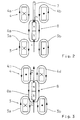
- Fig. 2 shows a schematic representation of the magnetic flux of the two coils 3, 4 from Fig. 1 and the arranged on the anchor rod 7 permanent magnet 8.
- the magnetic flux and its direction is in the coils 3, 4 marked by arrows oval lines 3a, 3b, 4a, 4b.
- the current direction in the two coils 3, 4 is represented by the symbols point ( ⁇ ) and cross (X).
- the magnetic flux of the permanent magnet 8, which has a north pole N and a south pole S, is indicated by the line trace 8a.
- the representation of the current flow and the magnetic flux corresponds to the switching process in which the permanent magnet 8 in its center position (see. Fig. 1 ) is moved.
- both coils 3, 4 are traversed by the current in the same direction, ie they form identical magnetic fields 3a, 3b, 4a, 4b.
- the coil 3 forms on the side facing the permanent magnet 8 a south pole and the coil 4 on the permanent magnet 8 side facing a north pole with the result that on the north pole N and the south pole S of the permanent magnet 8 each repulsive forces F act.
- the permanent magnet 8 is thus moved in its central position between the two coils 3, 4. There he is through the holding pole 16 (see. Fig. 1 ) - magnetically locked as described above. After the permanent magnet 8 has reached its stable center position, the coils 3, 4 are de-energized.
- Fig. 3 shows a schematic representation of the coils 3, 4 in a switching operation, by which the permanent magnet 8 and the actuator 15 (see. Fig. 1 ) is moved to an end position.
- the coils 3, 4 are traversed in opposite directions from the current, the lower coil 3 as the coil 3 in Fig. 2 is switched. Therefore, the magnetic flux is also denoted by 3a, 3b.
Landscapes
- Physics & Mathematics (AREA)
- Electromagnetism (AREA)
- Engineering & Computer Science (AREA)
- Power Engineering (AREA)
- Electromagnets (AREA)
- Reciprocating, Oscillating Or Vibrating Motors (AREA)
- Rear-View Mirror Devices That Are Mounted On The Exterior Of The Vehicle (AREA)
Abstract
Description
Die Erfindung betrifft eine elektromagnetische Stellvorrichtung nach dem Oberbegriff des Patentanspruches 1.The invention relates to an electromagnetic actuator according to the preamble of claim 1.
Elektromagnetische Stellvorrichtungen, auch Aktoren oder Aktuatoren, Stellmotore oder Hubmagnete genannt, sind in der Regelungstechnik bekannt. Beispielsweise dienen sie dem Antrieb oder der Verstellung von Ventilen oder Klappen zur Durchflussregelung von gasförmigen oder flüssigen Medien. Die meisten elektromagnetischen Aktuatoren sind bistabil, d. h. sie weisen nur zwei stabile Stellungen auf, z. B. auf oder zu.Electromagnetic actuators, also called actuators or actuators, servo motors or solenoids, are known in control engineering. For example, they are used to drive or adjust valves or valves for flow control of gaseous or liquid media. Most electromagnetic actuators are bistable, i. H. they have only two stable positions, z. B. open or close.
Durch die
Durch die
Neben den bistabilen sind auch tristabile Aktuatoren bekannt: Durch die
Es ist Aufgabe der vorliegenden Erfindung, eine elektromagnetische Stellvorrichtung der eingangs genannten Art mit geringem konstruktiven Aufwand und einer verminderten Zahl von Einzelteilen kostengünstig herzustellen.It is an object of the present invention to produce an electromagnetic actuator of the type mentioned with low design cost and a reduced number of items cost.
Die Aufgabe der Erfindung wird durch die Merkmale des Patentanspruches 1 gelöst.The object of the invention is solved by the features of claim 1.
In vorteilhafter Ausgestaltung sind die beiden Spulen jeweils an den Enden eines Polrohres, d. h. eines Rohres aus magnetischem Werkstoff angeordnet und weisen jeweils ein Joch, vorzugsweise aus einem ferromagnetischen Werkstoff auf. Damit wird der Magnetfluss über Joch und Polrohr geleitet, sodass je nach Bestromung der Spule eine unterschiedliche Polarität ausgebildet werden kann.In an advantageous embodiment, the two coils are each at the ends of a pole tube, d. H. a tube of magnetic material and each have a yoke, preferably made of a ferromagnetic material. Thus, the magnetic flux is passed through the yoke and pole tube, so that depending on the energization of the coil, a different polarity can be formed.
In weiterer vorteilhafter Ausgestaltung ist die Stellstange koaxial zum Polrohr angeordnet und innerhalb von Öffnungen der Joche gleitend gelagert. Dem Permanentmagneten ist ein vorzugsweise ringförmig ausgebildeter Haltepol zugeordnet, welcher bevorzugt innerhalb des Polrohres und etwa in der Mitte zwischen den beiden Spulen angeordnet ist. Der Haltepol ist aus einem magnetischen Werkstoff hergestellt und wird - bei der dritten Raststellung, d. h. der Mittelstellung des Ankers - vom Magnetfluss des Permanentmagneten durchflutet. Durch den Magnetschluss zwischen Haltepol und Permanentmagnet ergibt sich eine magnetische Arretierung des Stellgliedes bei stromlosen Spulen.In a further advantageous embodiment, the control rod is arranged coaxially to the pole tube and slidably mounted within openings of the yokes. The permanent magnet is assigned a preferably ring-shaped holding pole, which preferably within the pole tube and approximately in the Middle is arranged between the two coils. The holding pole is made of a magnetic material and is - flooded by the magnetic flux of the permanent magnet - in the third detent position, ie the center position of the armature. The magnetic connection between the holding pole and the permanent magnet results in a magnetic locking of the actuator with currentless coils.
Zur Verstärkung des Magnetflusses des Permanentmagneten können auf dessen Stirnseiten Flussbleche angeordnet sein. Vorteilhaft ist es auch, wenn auf den Flussblechen zusätzlich Antiklebscheiben angeordnet sind, welche ein Anhaften des Permanentmagneten am Spulenjoch verhindern.To reinforce the magnetic flux of the permanent magnet flow plates can be arranged on the end faces. It is also advantageous if additionally anti-adhesive discs are arranged on the flow plates, which prevent the permanent magnet from adhering to the coil yoke.
In weiterer vorteilhafter Ausgestaltung sind auf den Stirnseiten des Permanentmagneten vorzugsweise konisch ausgebildete Tauchanker vorgesehen, welche in entsprechende Öffnungen im Spulenjoch eintauchen. Damit wird die magnetische Anziehungskraft der Spulen auf das Stellglied erhöht.In a further advantageous embodiment, preferably conical plunger anchors are provided on the end faces of the permanent magnet, which dip into corresponding openings in the coil yoke. This increases the magnetic attraction of the coils on the actuator.
In weiterer vorteilhafter Ausgestaltung ist die Polarität des Permanentmagneten in Verschieberichtung des Stellgliedes und der Stellstange ausgerichtet. Dadurch wird auf einer Stirnseite ein Nordpol und auf der entgegengesetzten Stirnseite des Permanentmagneten ein Südpol gebildet. Je nach Bestromung der Spulen können somit eine Anziehungskraft und/oder eine abstoßende Kraft auf den Permanentmagneten ausgeübt werden, sodass dieser in die eine oder andere Endlage verschoben wird.In a further advantageous embodiment, the polarity of the permanent magnet is aligned in the direction of displacement of the actuator and the control rod. As a result, a north pole is formed on one end face and a south pole is formed on the opposite end face of the permanent magnet. Depending on the energization of the coils thus an attractive force and / or a repulsive force can be exerted on the permanent magnet, so that it is moved to one or the other end position.
In weiterer vorteilhafter Ausgestaltung kann im Bereich des Haltepols eine weitere Spule, eine so genannte Mittelspule, angeordnet sein, welche bei entsprechender Bestromung die arretierende Wirkung des Permanentmagneten in seiner Mittelstellung aufhebt und damit eine schnellere Verstellung des Stellgliedes in die eine oder andere Endlage erlaubt. Damit wird die Dynamik des Aktuators verbessert.In a further advantageous embodiment, in the region of the holding pole, a further coil, a so-called center coil, can be arranged which, with appropriate energization, cancels the arresting effect of the permanent magnet in its middle position and thus permits a faster adjustment of the actuator into one or the other end position. This improves the dynamics of the actuator.
Ein Ausführungsbeispiel der Erfindung ist in der Zeichnung dargestellt und wird im Folgenden näher beschrieben. Es zeigen
-
Fig. 1 eine erfindungsgemäße elektromagnetische Stellvorrichtung im Schnitt, -
Fig. 2 eine schematische Darstellung des Magnetflusses beim Schalten in die Mittelstellung und -
Fig. 3 eine schematische Darstellung des Magnetflusses beim Schalten in die Endlagen.
-
Fig. 1 an inventive electromagnetic actuator in section, -
Fig. 2 a schematic representation of the magnetic flux when switching to the center position and -
Fig. 3 a schematic representation of the magnetic flux when switching to the end positions.
- 11
- elektrodynamischer Aktuatorelectrodynamic actuator
- 22
- Polrohrpole tube
- 33
- SpuleKitchen sink
- 3a3a
- Magnetflussmagnetic flux
- 3b3b
- Magnetflussmagnetic flux
- 44
- SpuleKitchen sink
- 4a4a
- Magnetflussmagnetic flux
- 4b4b
- Magnetflussmagnetic flux
- 4c4c
- Magnetflussmagnetic flux
- 4d4d
- Magnetflussmagnetic flux
- 55
- Jochyoke
- 5a5a
- Öffnungopening
- 66
- Jochyoke
- 6a6a
- Öffnungopening
- 77
- Stellstangecontrol rod
- 88th
- Permanentmagnetpermanent magnet
- 8a8a
- Magnetflussmagnetic flux
- 99
- Flussleitblechflux deflector
- 1010
- Flussleitblechflux deflector
- 1111
- Antiklebscheibeanti-adhesion disc
- 1212
- Antiklebscheibeanti-adhesion disc
- 1313
- Tauchankerplunger
- 1414
- Tauchankerplunger
- 1515
- Stellgliedactuator
- 1616
- HaltepolHaltepol
- 1717
- Mittelspulemeans coil
- NN
- NordpolNorth Pole
- SS
- SüdpolSouth Pole
- FF
- Magnetkraftmagnetic force
- F1F1
- Schubkraftthrust
- F2F2
- Zugkrafttraction
Claims (12)
- Electromagnetic actuating apparatus (1) having a longitudinally moving actuating element (15) which can be locked in three latching positions and comprises an actuating rod (7) and a permanent magnet (8), and also having two coils (3, 4) by means of which the actuating element (15) can be switched into a first or a second latching position, the end positions, it being possible for the actuating apparatus to be magnetically locked by the permanent magnet in the third latching position, characterized in that current can flow through the two coils (3, 4) in the same direction and in the opposite direction, and in that the actuating element (15) comprises the permanent magnet (8) which is arranged on the actuating rod (7).
- Actuating apparatus according to Claim 1, characterized in that the coils (3, 4) are arranged at the ends in a pole tube (2).
- Actuating apparatus according to Claim 1 or 2, characterized in that the actuating rod (7) is arranged coaxially to the pole tube (2).
- Actuating apparatus according to Claim 1, 2 or 3, characterized in that the permanent magnet (8) - as seen in the axial direction - is arranged between the coils (3, 4).
- Actuating apparatus according to one of the preceding claims, characterized in that a retaining pole (16) is arranged between the coils (3, 4).
- Actuating apparatus according to Claim 5, characterized in that the retaining pole (16) is of annular design and forms a closed magnetic circuit with the permanent magnet (8) in the third latching position.
- Actuating apparatus according to one of the preceding claims, characterized in that the permanent magnet (8) has an axially oriented polarity (N, S).
- Actuating apparatus according to one of the preceding claims, characterized in that flux guide plates (9, 10) are arranged on the end faces of the permanent magnet (8).
- Actuating apparatus according to Claim 8, characterized in that anti-adhesive means, in particular anti-adhesive discs (11, 12), are arranged on the flux guide plates (9, 10).
- Actuating apparatus according to one of the preceding claims, characterized in that the coils (3, 4) each have a yoke (5, 6) with a coaxial opening (5a, 6a).
- Actuating apparatus according to Claim 10, characterized in that plunger-type armatures (13, 14) are arranged on the actuating rod (7) on either side of the permanent magnet (8), it being possible for said plunger-type armatures to enter the openings (5a, 6a).
- Actuating apparatus according to one of Claims 5 to 11, characterized in that a further coil, a central coil (17), is arranged in the region of the retaining pole (16).
Applications Claiming Priority (2)
| Application Number | Priority Date | Filing Date | Title |
|---|---|---|---|
| DE102008000534A DE102008000534A1 (en) | 2008-03-06 | 2008-03-06 | Electromagnetic actuator |
| PCT/EP2009/051535 WO2009109444A1 (en) | 2008-03-06 | 2009-02-11 | Electromagnetic actuating mechanism |
Publications (2)
| Publication Number | Publication Date |
|---|---|
| EP2250651A1 EP2250651A1 (en) | 2010-11-17 |
| EP2250651B1 true EP2250651B1 (en) | 2011-08-03 |
Family
ID=40474689
Family Applications (1)
| Application Number | Title | Priority Date | Filing Date |
|---|---|---|---|
| EP09718492A Active EP2250651B1 (en) | 2008-03-06 | 2009-02-11 | Electromagnetic actuating mechanism |
Country Status (8)
| Country | Link |
|---|---|
| US (1) | US8228149B2 (en) |
| EP (1) | EP2250651B1 (en) |
| JP (1) | JP2011513979A (en) |
| KR (1) | KR20100125287A (en) |
| CN (1) | CN101946292A (en) |
| AT (1) | ATE519207T1 (en) |
| DE (1) | DE102008000534A1 (en) |
| WO (1) | WO2009109444A1 (en) |
Families Citing this family (51)
| Publication number | Priority date | Publication date | Assignee | Title |
|---|---|---|---|---|
| GB0822760D0 (en) * | 2008-12-13 | 2009-01-21 | Camcon Ltd | Bistable electromagnetic actuator |
| DE102009026543A1 (en) | 2009-05-28 | 2010-12-02 | Zf Friedrichshafen Ag | Automated motorcycle transmission |
| EP2504606B1 (en) * | 2009-11-23 | 2019-05-08 | BeijingWest Industries Co., Ltd | Bi-stable solenoid shock absorber assembly |
| EP2339681B1 (en) * | 2009-12-18 | 2013-09-18 | Bayerische Motoren Werke Aktiengesellschaft | Electromagnetic actuator |
| WO2011128516A1 (en) * | 2010-04-15 | 2011-10-20 | Schneider Elect4Ic Industries Sas | Electrical switching device having an ultrafast actuation mechanism and hybrid switch comprising such a device |
| KR101388085B1 (en) * | 2010-06-10 | 2014-04-22 | 엘에스산전 주식회사 | Bistable permanent magnetic actuator |
| DE102010041086A1 (en) * | 2010-09-21 | 2012-03-22 | Zf Friedrichshafen Ag | Actuator device and method for driving |
| DE102010050755B4 (en) * | 2010-11-10 | 2012-10-04 | Eto Magnetic Gmbh | Multi-stable electromagnetic actuator |
| US8212640B1 (en) * | 2011-07-26 | 2012-07-03 | Lockheed Martin Corporation | Tool having buffered electromagnet drive for depth control |
| DE102011053023A1 (en) * | 2011-08-26 | 2013-02-28 | Hilite Germany Gmbh | Hydraulic transmission valve |
| US20130236337A1 (en) * | 2012-03-09 | 2013-09-12 | Mark A. Gummin | Solenoid actuators using embedded printed circuit coils |
| US9183976B2 (en) | 2012-03-19 | 2015-11-10 | Hanchett Entry Systems, Inc. | Springless electromagnet actuator having a mode selectable magnetic armature |
| DE102012204322B4 (en) | 2012-03-19 | 2022-07-14 | Zf Friedrichshafen Ag | Bidirectional electromagnetic actuator |
| JP6029854B2 (en) * | 2012-05-22 | 2016-11-24 | ミネベア株式会社 | Vibrator and vibration generator |
| DE102012107281B4 (en) | 2012-08-08 | 2014-03-06 | Eto Magnetic Gmbh | Bistable electromagnetic actuator, armature assembly and camshaft adjuster |
| DE102012214624A1 (en) * | 2012-08-17 | 2014-02-20 | Robert Bosch Gmbh | Pole tube for an actuator device |
| DE102012018566A1 (en) * | 2012-09-20 | 2014-03-20 | Festo Ag & Co. Kg | Valve device for use as e.g. proportional valve, has valve housing provided with permanent magnet arrangement, and multiple flux conductive pieces arranged on axis of electrical operable coil arrangement |
| US9390875B2 (en) * | 2013-05-29 | 2016-07-12 | Active Signal Technologies, Inc. | Electromagnetic opposing field actuators |
| US10528024B2 (en) | 2013-06-17 | 2020-01-07 | Ashley Stone | Self-learning production systems with good and/or bad part variables inspection feedback |
| US9352501B2 (en) | 2013-06-17 | 2016-05-31 | Ashley Stone | Molding systems and methods |
| DE102013013585B4 (en) * | 2013-06-20 | 2020-09-17 | Rhefor Gbr | Self-holding magnet with particularly low electrical tripping power |
| US9576714B2 (en) * | 2013-07-11 | 2017-02-21 | Siemens Aktiengesellschaft | Magnetic actuator |
| FR3012251B1 (en) | 2013-10-21 | 2017-03-10 | Schneider Electric Ind Sas | ELECTROMAGNETIC ACTUATOR AND METHOD FOR MANUFACTURING SUCH ACTUATOR |
| US10522313B2 (en) | 2013-10-23 | 2019-12-31 | Rhefor Gbr | Reversing linear solenoid |
| CN105659481B (en) | 2013-10-23 | 2020-02-11 | 雷福尔公司 | Electromechanical actuator |
| FI20145100L (en) * | 2014-01-30 | 2015-07-31 | Ixtur Oy | Magnet |
| CN105090596B (en) * | 2014-05-14 | 2018-04-27 | 浙江三花制冷集团有限公司 | Solenoid valve and bistable electro magnetic coil |
| KR200488063Y1 (en) * | 2014-06-30 | 2018-12-10 | 엘에스산전 주식회사 | Relay |
| DE102014217738B4 (en) * | 2014-09-04 | 2023-03-30 | Zf Friedrichshafen Ag | Method and device for controlling an electromagnetic actuator |
| DE102015101734A1 (en) * | 2015-02-06 | 2016-08-11 | Kendrion (Donaueschingen/Engelswies) GmbH | Electromagnetic lifting device |
| DE102015204104A1 (en) * | 2015-03-06 | 2016-09-08 | Zf Friedrichshafen Ag | Electromagnetic switching device and method for operating an electromagnetic switching device |
| US9709006B2 (en) | 2015-04-08 | 2017-07-18 | Ford Global Technologies, Llc | Systems and methods for depressurizing a fuel tank |
| JP6587472B2 (en) * | 2015-09-14 | 2019-10-09 | 日本電産トーソク株式会社 | Actuator |
| US10851907B2 (en) | 2015-11-09 | 2020-12-01 | Husco Automotive Holdings Llc | System and methods for an electromagnetic actuator |
| JP2017169433A (en) | 2016-03-17 | 2017-09-21 | フスコ オートモーティブ ホールディングス エル・エル・シーHUSCO Automotive Holdings LLC | Systems and methods for electromagnetic actuator |
| WO2017171757A1 (en) * | 2016-03-30 | 2017-10-05 | Intel Corporation | Electromagnetic haptic actuator integral with a multilayer substrate |
| DE102016106805A1 (en) * | 2016-04-13 | 2017-10-19 | Eto Magnetic Gmbh | Electroless monostable electromagnetic actuator and use of such |
| US10024453B2 (en) * | 2016-07-15 | 2018-07-17 | Glen A. Robertson | Dual acting solenoid valve using bi-stable permanent magnet activation for energy efficiency and power versatility |
| CN106298155B (en) * | 2016-11-07 | 2017-09-12 | 温州大学 | A kind of coiled electrical magnet |
| CN106409467B (en) * | 2016-11-12 | 2017-10-17 | 温州大学 | The two-way compound coiled electrical magnet of high speed ratio |
| CN106531547B (en) * | 2016-12-16 | 2019-12-13 | 黑龙江博瑞特高新技术开发有限公司 | Bistable permanent magnet operating device for automatic mutual switching of high-voltage dual power supplies and control method |
| DE102017103027A1 (en) * | 2017-02-15 | 2018-08-16 | Rausch & Pausch Gmbh | LINEAR |
| DE102017212084A1 (en) * | 2017-07-14 | 2019-01-17 | Robert Bosch Gmbh | Bistable solenoid valve for a hydraulic brake system and method for controlling such a valve |
| JP7393125B2 (en) * | 2018-03-13 | 2023-12-06 | フスコ オートモーティブ ホールディングス エル・エル・シー | Bistable solenoid with intermediate states |
| US11448103B2 (en) * | 2018-06-28 | 2022-09-20 | Board Of Regents, The University Of Texas System | Electromagnetic soft actuators |
| KR102324514B1 (en) * | 2018-08-31 | 2021-11-10 | 엘에스일렉트릭 (주) | Direct Current Relay |
| US11640864B2 (en) * | 2019-12-05 | 2023-05-02 | Deltrol Corp. | System and method for detecting position of a solenoid plunger |
| DE102019133333A1 (en) * | 2019-12-06 | 2021-06-10 | Eto Magnetic Gmbh | Electromagnetic actuator with intermediate position |
| SG10202004135RA (en) * | 2020-05-05 | 2021-12-30 | Soon Seng Sin | Levitation and propulsion unit - two (lpu-2) |
| KR102391658B1 (en) * | 2020-06-01 | 2022-04-27 | 충남대학교산학협력단 | Actuator with gravity compensation |
| EP3982379A1 (en) * | 2020-10-08 | 2022-04-13 | The Swatch Group Research and Development Ltd | Micro-actuator with magnetically retracting solenoid |
Citations (1)
| Publication number | Priority date | Publication date | Assignee | Title |
|---|---|---|---|---|
| DE1892313U (en) * | 1964-03-09 | 1964-05-06 | Harting Elektro W | ELECTRIC LIFTING MAGNET WITH THREE RESTING POSITIONS. |
Family Cites Families (29)
| Publication number | Priority date | Publication date | Assignee | Title |
|---|---|---|---|---|
| GB258725A (en) * | 1925-09-05 | 1926-09-30 | Peter Grant | Improvements in or relating to electromagnetically actuated hammers, drills, vibrators, and other reciprocating or vibrating tools or devices |
| US3070730A (en) * | 1960-08-22 | 1962-12-25 | Bendix Corp | Three-position latching solenoid actuator |
| US3202886A (en) * | 1962-01-11 | 1965-08-24 | Bulova Watch Co Inc | Bistable solenoid |
| CH485207A (en) * | 1967-11-30 | 1970-01-31 | Ebauches Sa | Linear Acting Current-Force Transducer |
| JPS4933109A (en) * | 1972-08-02 | 1974-03-27 | ||
| CA1132646A (en) * | 1979-06-05 | 1982-09-28 | Christian C. Petersen | Linear motor |
| JPS591412Y2 (en) * | 1979-11-15 | 1984-01-14 | 松下電工株式会社 | Reciprocating electromagnet |
| JPS5829754U (en) * | 1981-08-21 | 1983-02-26 | 日立金属株式会社 | Actuator for door lock |
| US4870306A (en) * | 1981-10-08 | 1989-09-26 | Polaroid Corporation | Method and apparatus for precisely moving a motor armature |
| JPS58192460A (en) * | 1982-05-01 | 1983-11-09 | Takahashi Denki Kk | Self-holding linear motor |
| JPS59126608A (en) * | 1983-01-07 | 1984-07-21 | Aisin Seiki Co Ltd | Solenoid apparatus |
| DE3402768C2 (en) * | 1984-01-27 | 1985-12-19 | Thyssen Edelstahlwerke Ag, 4000 Duesseldorf | Bistable magnetic actuator |
| US4533890A (en) * | 1984-12-24 | 1985-08-06 | General Motors Corporation | Permanent magnet bistable solenoid actuator |
| US4829947A (en) * | 1987-08-12 | 1989-05-16 | General Motors Corporation | Variable lift operation of bistable electromechanical poppet valve actuator |
| US4928028A (en) * | 1989-02-23 | 1990-05-22 | Hydraulic Units, Inc. | Proportional permanent magnet force actuator |
| EP0580117A3 (en) * | 1992-07-20 | 1994-08-24 | Tdk Corp | Moving magnet-type actuator |
| DE4400433C2 (en) * | 1994-01-10 | 1998-06-04 | Kokemor Manfred Dipl Ing Fh | Polarized multi-position magnet |
| DE19601541A1 (en) * | 1995-01-27 | 1996-08-01 | Seiko Seiki Kk | Vacuum chamber with vertical handling system and non-return valve |
| JP3633166B2 (en) * | 1996-12-28 | 2005-03-30 | アイシン・エィ・ダブリュ株式会社 | Linear solenoid |
| US5896076A (en) * | 1997-12-29 | 1999-04-20 | Motran Ind Inc | Force actuator with dual magnetic operation |
| JP3492228B2 (en) * | 1999-02-09 | 2004-02-03 | 株式会社テクノ高槻 | Iron core and electromagnetic drive mechanism using the iron core |
| JP3591429B2 (en) * | 2000-06-22 | 2004-11-17 | オムロンヘルスケア株式会社 | Flow control valve and sphygmomanometer |
| DE10207828B4 (en) | 2002-02-25 | 2004-10-07 | Technische Universität Dresden | Electromagnetic solenoid |
| DE20203718U1 (en) | 2002-03-07 | 2002-07-04 | Eto Magnetic Kg | Electromagnetic actuator |
| US20050046531A1 (en) * | 2002-10-09 | 2005-03-03 | David Moyer | Electromagnetic valve system |
| DE10309697B3 (en) * | 2003-02-26 | 2004-09-02 | Siemens Ag | Magnetic linear drive |
| DE102004004708B3 (en) * | 2004-01-30 | 2005-04-21 | Karl Dungs Gmbh & Co. Kg | Magnetically-operated double-seat valve for shutting off fluid flow has armature moving circular seal engaging triangular-section seat and surrounding inner valve with triangular-section seal |
| KR100598532B1 (en) * | 2004-12-20 | 2006-07-10 | 현대자동차주식회사 | Linear EMV actuator using permanent magnet and electro magnet |
| DE202007007385U1 (en) * | 2007-05-23 | 2007-11-29 | Kuhnke Automation Gmbh & Co. Kg | Actuating magnet for moving a valve needle of a hot runner nozzle of an injection molding tool |
-
2008
- 2008-03-06 DE DE102008000534A patent/DE102008000534A1/en not_active Withdrawn
-
2009
- 2009-02-11 US US12/864,892 patent/US8228149B2/en active Active
- 2009-02-11 WO PCT/EP2009/051535 patent/WO2009109444A1/en active Application Filing
- 2009-02-11 EP EP09718492A patent/EP2250651B1/en active Active
- 2009-02-11 JP JP2010549071A patent/JP2011513979A/en active Pending
- 2009-02-11 AT AT09718492T patent/ATE519207T1/en active
- 2009-02-11 CN CN2009801051027A patent/CN101946292A/en active Pending
- 2009-02-11 KR KR1020107019647A patent/KR20100125287A/en not_active Application Discontinuation
Patent Citations (1)
| Publication number | Priority date | Publication date | Assignee | Title |
|---|---|---|---|---|
| DE1892313U (en) * | 1964-03-09 | 1964-05-06 | Harting Elektro W | ELECTRIC LIFTING MAGNET WITH THREE RESTING POSITIONS. |
Also Published As
| Publication number | Publication date |
|---|---|
| CN101946292A (en) | 2011-01-12 |
| WO2009109444A1 (en) | 2009-09-11 |
| JP2011513979A (en) | 2011-04-28 |
| US8228149B2 (en) | 2012-07-24 |
| ATE519207T1 (en) | 2011-08-15 |
| EP2250651A1 (en) | 2010-11-17 |
| US20110001591A1 (en) | 2011-01-06 |
| KR20100125287A (en) | 2010-11-30 |
| DE102008000534A1 (en) | 2009-09-10 |
Similar Documents
| Publication | Publication Date | Title |
|---|---|---|
| EP2250651B1 (en) | Electromagnetic actuating mechanism | |
| DE4012832C2 (en) | magnetic valve | |
| EP2880696A1 (en) | Actuator device | |
| EP1069357A2 (en) | Actuator for solenoid valve | |
| DE102016203602A1 (en) | Electromagnetic actuator and valve | |
| DE10310448B4 (en) | Electromagnetic actuator | |
| DE19922414C1 (en) | Solenoid operated valve | |
| DE102011014192A1 (en) | Electromagnetic actuating device, has coil unit activated by energization of magnetic flux shift i.e. magnetic flux displacement, of permanent magnetic fluxes from yoke section to another yoke section | |
| EP2474009B1 (en) | Bistable electromagnetic actuating device | |
| EP1634309B1 (en) | Electromagnetic drive device | |
| EP3185256B1 (en) | Electromagnet | |
| EP3791095B1 (en) | Process component | |
| DE3542097A1 (en) | Adjustable valve for a vibration damper and method for controlling this | |
| DE102011081893B3 (en) | Magnetic actuator and method for its operation | |
| DE102017211257B4 (en) | Electromagnetic actuator and valve equipped with it | |
| DE10153002B4 (en) | Turntable with lifting magnet and lifting magnet | |
| DE4442190C2 (en) | Single stroke magnet | |
| DE4403420A1 (en) | Linear electromagnetic drive for control elements | |
| EP0030283B1 (en) | Actuating device for a distributing valve | |
| EP3086335B1 (en) | Magnet valve device for a fluid system and method for switching a solenoid valve | |
| DE1925182A1 (en) | Solenoid | |
| DE4400433C2 (en) | Polarized multi-position magnet | |
| DE4224470A1 (en) | Solenoid activated fluid power directional flow valve - has armature integral with sliding valve element used to control flow through valve ports. | |
| EP0224815A2 (en) | Adjustable valve system for a vibration damper, and method for adjusting or regulating of the same | |
| DE10357001B4 (en) | Magnetic linear actuator |
Legal Events
| Date | Code | Title | Description |
|---|---|---|---|
| PUAI | Public reference made under article 153(3) epc to a published international application that has entered the european phase |
Free format text: ORIGINAL CODE: 0009012 |
|
| 17P | Request for examination filed |
Effective date: 20100713 |
|
| AK | Designated contracting states |
Kind code of ref document: A1 Designated state(s): AT BE BG CH CY CZ DE DK EE ES FI FR GB GR HR HU IE IS IT LI LT LU LV MC MK MT NL NO PL PT RO SE SI SK TR |
|
| AX | Request for extension of the european patent |
Extension state: AL BA RS |
|
| GRAP | Despatch of communication of intention to grant a patent |
Free format text: ORIGINAL CODE: EPIDOSNIGR1 |
|
| GRAS | Grant fee paid |
Free format text: ORIGINAL CODE: EPIDOSNIGR3 |
|
| DAX | Request for extension of the european patent (deleted) | ||
| GRAA | (expected) grant |
Free format text: ORIGINAL CODE: 0009210 |
|
| AK | Designated contracting states |
Kind code of ref document: B1 Designated state(s): AT BE BG CH CY CZ DE DK EE ES FI FR GB GR HR HU IE IS IT LI LT LU LV MC MK MT NL NO PL PT RO SE SI SK TR |
|
| REG | Reference to a national code |
Ref country code: GB Ref legal event code: FG4D Free format text: NOT ENGLISH |
|
| REG | Reference to a national code |
Ref country code: CH Ref legal event code: EP |
|
| REG | Reference to a national code |
Ref country code: IE Ref legal event code: FG4D Free format text: LANGUAGE OF EP DOCUMENT: GERMAN |
|
| REG | Reference to a national code |
Ref country code: SE Ref legal event code: TRGR |
|
| REG | Reference to a national code |
Ref country code: DE Ref legal event code: R096 Ref document number: 502009001053 Country of ref document: DE Effective date: 20111013 |
|
| REG | Reference to a national code |
Ref country code: NL Ref legal event code: VDEP Effective date: 20110803 |
|
| LTIE | Lt: invalidation of european patent or patent extension |
Effective date: 20110803 |
|
| PG25 | Lapsed in a contracting state [announced via postgrant information from national office to epo] |
Ref country code: NL Free format text: LAPSE BECAUSE OF FAILURE TO SUBMIT A TRANSLATION OF THE DESCRIPTION OR TO PAY THE FEE WITHIN THE PRESCRIBED TIME-LIMIT Effective date: 20110803 Ref country code: PT Free format text: LAPSE BECAUSE OF FAILURE TO SUBMIT A TRANSLATION OF THE DESCRIPTION OR TO PAY THE FEE WITHIN THE PRESCRIBED TIME-LIMIT Effective date: 20111205 Ref country code: IS Free format text: LAPSE BECAUSE OF FAILURE TO SUBMIT A TRANSLATION OF THE DESCRIPTION OR TO PAY THE FEE WITHIN THE PRESCRIBED TIME-LIMIT Effective date: 20111203 Ref country code: NO Free format text: LAPSE BECAUSE OF FAILURE TO SUBMIT A TRANSLATION OF THE DESCRIPTION OR TO PAY THE FEE WITHIN THE PRESCRIBED TIME-LIMIT Effective date: 20111103 Ref country code: FI Free format text: LAPSE BECAUSE OF FAILURE TO SUBMIT A TRANSLATION OF THE DESCRIPTION OR TO PAY THE FEE WITHIN THE PRESCRIBED TIME-LIMIT Effective date: 20110803 Ref country code: HR Free format text: LAPSE BECAUSE OF FAILURE TO SUBMIT A TRANSLATION OF THE DESCRIPTION OR TO PAY THE FEE WITHIN THE PRESCRIBED TIME-LIMIT Effective date: 20110803 Ref country code: LT Free format text: LAPSE BECAUSE OF FAILURE TO SUBMIT A TRANSLATION OF THE DESCRIPTION OR TO PAY THE FEE WITHIN THE PRESCRIBED TIME-LIMIT Effective date: 20110803 |
|
| PG25 | Lapsed in a contracting state [announced via postgrant information from national office to epo] |
Ref country code: SI Free format text: LAPSE BECAUSE OF FAILURE TO SUBMIT A TRANSLATION OF THE DESCRIPTION OR TO PAY THE FEE WITHIN THE PRESCRIBED TIME-LIMIT Effective date: 20110803 Ref country code: PL Free format text: LAPSE BECAUSE OF FAILURE TO SUBMIT A TRANSLATION OF THE DESCRIPTION OR TO PAY THE FEE WITHIN THE PRESCRIBED TIME-LIMIT Effective date: 20110803 Ref country code: LV Free format text: LAPSE BECAUSE OF FAILURE TO SUBMIT A TRANSLATION OF THE DESCRIPTION OR TO PAY THE FEE WITHIN THE PRESCRIBED TIME-LIMIT Effective date: 20110803 Ref country code: GR Free format text: LAPSE BECAUSE OF FAILURE TO SUBMIT A TRANSLATION OF THE DESCRIPTION OR TO PAY THE FEE WITHIN THE PRESCRIBED TIME-LIMIT Effective date: 20111104 Ref country code: CY Free format text: LAPSE BECAUSE OF FAILURE TO SUBMIT A TRANSLATION OF THE DESCRIPTION OR TO PAY THE FEE WITHIN THE PRESCRIBED TIME-LIMIT Effective date: 20110803 |
|
| REG | Reference to a national code |
Ref country code: IE Ref legal event code: FD4D |
|
| PG25 | Lapsed in a contracting state [announced via postgrant information from national office to epo] |
Ref country code: IE Free format text: LAPSE BECAUSE OF FAILURE TO SUBMIT A TRANSLATION OF THE DESCRIPTION OR TO PAY THE FEE WITHIN THE PRESCRIBED TIME-LIMIT Effective date: 20110803 Ref country code: CZ Free format text: LAPSE BECAUSE OF FAILURE TO SUBMIT A TRANSLATION OF THE DESCRIPTION OR TO PAY THE FEE WITHIN THE PRESCRIBED TIME-LIMIT Effective date: 20110803 Ref country code: SK Free format text: LAPSE BECAUSE OF FAILURE TO SUBMIT A TRANSLATION OF THE DESCRIPTION OR TO PAY THE FEE WITHIN THE PRESCRIBED TIME-LIMIT Effective date: 20110803 |
|
| PG25 | Lapsed in a contracting state [announced via postgrant information from national office to epo] |
Ref country code: EE Free format text: LAPSE BECAUSE OF FAILURE TO SUBMIT A TRANSLATION OF THE DESCRIPTION OR TO PAY THE FEE WITHIN THE PRESCRIBED TIME-LIMIT Effective date: 20110803 Ref country code: RO Free format text: LAPSE BECAUSE OF FAILURE TO SUBMIT A TRANSLATION OF THE DESCRIPTION OR TO PAY THE FEE WITHIN THE PRESCRIBED TIME-LIMIT Effective date: 20110803 |
|
| PLBE | No opposition filed within time limit |
Free format text: ORIGINAL CODE: 0009261 |
|
| STAA | Information on the status of an ep patent application or granted ep patent |
Free format text: STATUS: NO OPPOSITION FILED WITHIN TIME LIMIT |
|
| PG25 | Lapsed in a contracting state [announced via postgrant information from national office to epo] |
Ref country code: DK Free format text: LAPSE BECAUSE OF FAILURE TO SUBMIT A TRANSLATION OF THE DESCRIPTION OR TO PAY THE FEE WITHIN THE PRESCRIBED TIME-LIMIT Effective date: 20110803 |
|
| PGFP | Annual fee paid to national office [announced via postgrant information from national office to epo] |
Ref country code: IT Payment date: 20120228 Year of fee payment: 4 |
|
| 26N | No opposition filed |
Effective date: 20120504 |
|
| REG | Reference to a national code |
Ref country code: DE Ref legal event code: R097 Ref document number: 502009001053 Country of ref document: DE Effective date: 20120504 |
|
| BERE | Be: lapsed |
Owner name: ZF FRIEDRICHSHAFEN A.G. Effective date: 20120228 |
|
| PG25 | Lapsed in a contracting state [announced via postgrant information from national office to epo] |
Ref country code: MC Free format text: LAPSE BECAUSE OF NON-PAYMENT OF DUE FEES Effective date: 20120229 |
|
| PG25 | Lapsed in a contracting state [announced via postgrant information from national office to epo] |
Ref country code: BE Free format text: LAPSE BECAUSE OF NON-PAYMENT OF DUE FEES Effective date: 20120228 |
|
| PG25 | Lapsed in a contracting state [announced via postgrant information from national office to epo] |
Ref country code: MK Free format text: LAPSE BECAUSE OF FAILURE TO SUBMIT A TRANSLATION OF THE DESCRIPTION OR TO PAY THE FEE WITHIN THE PRESCRIBED TIME-LIMIT Effective date: 20110803 |
|
| PG25 | Lapsed in a contracting state [announced via postgrant information from national office to epo] |
Ref country code: ES Free format text: LAPSE BECAUSE OF FAILURE TO SUBMIT A TRANSLATION OF THE DESCRIPTION OR TO PAY THE FEE WITHIN THE PRESCRIBED TIME-LIMIT Effective date: 20111114 |
|
| PG25 | Lapsed in a contracting state [announced via postgrant information from national office to epo] |
Ref country code: BG Free format text: LAPSE BECAUSE OF FAILURE TO SUBMIT A TRANSLATION OF THE DESCRIPTION OR TO PAY THE FEE WITHIN THE PRESCRIBED TIME-LIMIT Effective date: 20111103 |
|
| PG25 | Lapsed in a contracting state [announced via postgrant information from national office to epo] |
Ref country code: MT Free format text: LAPSE BECAUSE OF FAILURE TO SUBMIT A TRANSLATION OF THE DESCRIPTION OR TO PAY THE FEE WITHIN THE PRESCRIBED TIME-LIMIT Effective date: 20110803 |
|
| REG | Reference to a national code |
Ref country code: CH Ref legal event code: PL |
|
| GBPC | Gb: european patent ceased through non-payment of renewal fee |
Effective date: 20130211 |
|
| PG25 | Lapsed in a contracting state [announced via postgrant information from national office to epo] |
Ref country code: LI Free format text: LAPSE BECAUSE OF NON-PAYMENT OF DUE FEES Effective date: 20130228 Ref country code: CH Free format text: LAPSE BECAUSE OF NON-PAYMENT OF DUE FEES Effective date: 20130228 |
|
| PG25 | Lapsed in a contracting state [announced via postgrant information from national office to epo] |
Ref country code: GB Free format text: LAPSE BECAUSE OF NON-PAYMENT OF DUE FEES Effective date: 20130211 |
|
| PG25 | Lapsed in a contracting state [announced via postgrant information from national office to epo] |
Ref country code: TR Free format text: LAPSE BECAUSE OF FAILURE TO SUBMIT A TRANSLATION OF THE DESCRIPTION OR TO PAY THE FEE WITHIN THE PRESCRIBED TIME-LIMIT Effective date: 20110803 |
|
| PG25 | Lapsed in a contracting state [announced via postgrant information from national office to epo] |
Ref country code: LU Free format text: LAPSE BECAUSE OF NON-PAYMENT OF DUE FEES Effective date: 20120211 |
|
| PG25 | Lapsed in a contracting state [announced via postgrant information from national office to epo] |
Ref country code: HU Free format text: LAPSE BECAUSE OF FAILURE TO SUBMIT A TRANSLATION OF THE DESCRIPTION OR TO PAY THE FEE WITHIN THE PRESCRIBED TIME-LIMIT Effective date: 20090211 |
|
| REG | Reference to a national code |
Ref country code: AT Ref legal event code: MM01 Ref document number: 519207 Country of ref document: AT Kind code of ref document: T Effective date: 20140211 |
|
| PG25 | Lapsed in a contracting state [announced via postgrant information from national office to epo] |
Ref country code: AT Free format text: LAPSE BECAUSE OF NON-PAYMENT OF DUE FEES Effective date: 20140211 |
|
| REG | Reference to a national code |
Ref country code: FR Ref legal event code: PLFP Year of fee payment: 8 |
|
| PGFP | Annual fee paid to national office [announced via postgrant information from national office to epo] |
Ref country code: SE Payment date: 20160211 Year of fee payment: 8 Ref country code: FR Payment date: 20160108 Year of fee payment: 8 |
|
| PG25 | Lapsed in a contracting state [announced via postgrant information from national office to epo] |
Ref country code: IT Free format text: LAPSE BECAUSE OF NON-PAYMENT OF DUE FEES Effective date: 20140211 |
|
| REG | Reference to a national code |
Ref country code: SE Ref legal event code: EUG |
|
| PG25 | Lapsed in a contracting state [announced via postgrant information from national office to epo] |
Ref country code: SE Free format text: LAPSE BECAUSE OF NON-PAYMENT OF DUE FEES Effective date: 20170212 |
|
| REG | Reference to a national code |
Ref country code: FR Ref legal event code: ST Effective date: 20171031 |
|
| PG25 | Lapsed in a contracting state [announced via postgrant information from national office to epo] |
Ref country code: FR Free format text: LAPSE BECAUSE OF NON-PAYMENT OF DUE FEES Effective date: 20170228 |
|
| PGFP | Annual fee paid to national office [announced via postgrant information from national office to epo] |
Ref country code: DE Payment date: 20221220 Year of fee payment: 15 |
|
| P01 | Opt-out of the competence of the unified patent court (upc) registered |
Effective date: 20230528 |