EP2250410B1 - Dual seating quick connect valve - Google Patents
Dual seating quick connect valve Download PDFInfo
- Publication number
- EP2250410B1 EP2250410B1 EP20090716382 EP09716382A EP2250410B1 EP 2250410 B1 EP2250410 B1 EP 2250410B1 EP 20090716382 EP20090716382 EP 20090716382 EP 09716382 A EP09716382 A EP 09716382A EP 2250410 B1 EP2250410 B1 EP 2250410B1
- Authority
- EP
- European Patent Office
- Prior art keywords
- stem
- sealing portion
- valve
- cap
- deformable lip
- Prior art date
- Legal status (The legal status is an assumption and is not a legal conclusion. Google has not performed a legal analysis and makes no representation as to the accuracy of the status listed.)
- Not-in-force
Links
- 230000009977 dual effect Effects 0.000 title description 2
- 238000007789 sealing Methods 0.000 claims description 75
- 239000012530 fluid Substances 0.000 claims description 45
- 238000006073 displacement reaction Methods 0.000 claims description 14
- -1 poly(styrene-butadiene-styrene) Polymers 0.000 description 10
- 239000000463 material Substances 0.000 description 7
- 229920000642 polymer Polymers 0.000 description 5
- 239000007788 liquid Substances 0.000 description 4
- 239000000654 additive Substances 0.000 description 2
- 238000000034 method Methods 0.000 description 2
- 229920003229 poly(methyl methacrylate) Polymers 0.000 description 2
- 239000004926 polymethyl methacrylate Substances 0.000 description 2
- 229920002449 FKM Polymers 0.000 description 1
- 229920004459 Kel-F® PCTFE Polymers 0.000 description 1
- 229920000459 Nitrile rubber Polymers 0.000 description 1
- 239000005062 Polybutadiene Substances 0.000 description 1
- 229920002367 Polyisobutene Polymers 0.000 description 1
- 239000004809 Teflon Substances 0.000 description 1
- 229920006362 Teflon® Polymers 0.000 description 1
- 230000000996 additive effect Effects 0.000 description 1
- 230000009286 beneficial effect Effects 0.000 description 1
- 229920003237 carborane-containing polymer Polymers 0.000 description 1
- UUAGAQFQZIEFAH-UHFFFAOYSA-N chlorotrifluoroethylene Chemical compound FC(F)=C(F)Cl UUAGAQFQZIEFAH-UHFFFAOYSA-N 0.000 description 1
- 238000004891 communication Methods 0.000 description 1
- 229920001577 copolymer Polymers 0.000 description 1
- 238000004132 cross linking Methods 0.000 description 1
- 238000007865 diluting Methods 0.000 description 1
- 229920001971 elastomer Polymers 0.000 description 1
- 239000000806 elastomer Substances 0.000 description 1
- 238000003780 insertion Methods 0.000 description 1
- 230000037431 insertion Effects 0.000 description 1
- 239000000203 mixture Substances 0.000 description 1
- GKTNLYAAZKKMTQ-UHFFFAOYSA-N n-[bis(dimethylamino)phosphinimyl]-n-methylmethanamine Chemical compound CN(C)P(=N)(N(C)C)N(C)C GKTNLYAAZKKMTQ-UHFFFAOYSA-N 0.000 description 1
- 239000004014 plasticizer Substances 0.000 description 1
- 229920001084 poly(chloroprene) Polymers 0.000 description 1
- 229920002492 poly(sulfone) Polymers 0.000 description 1
- 229920002857 polybutadiene Polymers 0.000 description 1
- 229920001748 polybutylene Polymers 0.000 description 1
- 239000004417 polycarbonate Substances 0.000 description 1
- 229920000515 polycarbonate Polymers 0.000 description 1
- 229920001195 polyisoprene Polymers 0.000 description 1
- 229920001296 polysiloxane Polymers 0.000 description 1
- 229920002635 polyurethane Polymers 0.000 description 1
- 239000004814 polyurethane Substances 0.000 description 1
- 239000004800 polyvinyl chloride Substances 0.000 description 1
- 229920002981 polyvinylidene fluoride Polymers 0.000 description 1
- 229920001169 thermoplastic Polymers 0.000 description 1
- 239000004416 thermosoftening plastic Substances 0.000 description 1
Images


Classifications
-
- B—PERFORMING OPERATIONS; TRANSPORTING
- B41—PRINTING; LINING MACHINES; TYPEWRITERS; STAMPS
- B41J—TYPEWRITERS; SELECTIVE PRINTING MECHANISMS, i.e. MECHANISMS PRINTING OTHERWISE THAN FROM A FORME; CORRECTION OF TYPOGRAPHICAL ERRORS
- B41J2/00—Typewriters or selective printing mechanisms characterised by the printing or marking process for which they are designed
- B41J2/005—Typewriters or selective printing mechanisms characterised by the printing or marking process for which they are designed characterised by bringing liquid or particles selectively into contact with a printing material
- B41J2/01—Ink jet
- B41J2/17—Ink jet characterised by ink handling
- B41J2/175—Ink supply systems ; Circuit parts therefor
- B41J2/17596—Ink pumps, ink valves
-
- F—MECHANICAL ENGINEERING; LIGHTING; HEATING; WEAPONS; BLASTING
- F16—ENGINEERING ELEMENTS AND UNITS; GENERAL MEASURES FOR PRODUCING AND MAINTAINING EFFECTIVE FUNCTIONING OF MACHINES OR INSTALLATIONS; THERMAL INSULATION IN GENERAL
- F16K—VALVES; TAPS; COCKS; ACTUATING-FLOATS; DEVICES FOR VENTING OR AERATING
- F16K15/00—Check valves
- F16K15/14—Check valves with flexible valve members
- F16K15/148—Check valves with flexible valve members the closure elements being fixed in their centre
-
- Y—GENERAL TAGGING OF NEW TECHNOLOGICAL DEVELOPMENTS; GENERAL TAGGING OF CROSS-SECTIONAL TECHNOLOGIES SPANNING OVER SEVERAL SECTIONS OF THE IPC; TECHNICAL SUBJECTS COVERED BY FORMER USPC CROSS-REFERENCE ART COLLECTIONS [XRACs] AND DIGESTS
- Y10—TECHNICAL SUBJECTS COVERED BY FORMER USPC
- Y10T—TECHNICAL SUBJECTS COVERED BY FORMER US CLASSIFICATION
- Y10T137/00—Fluid handling
- Y10T137/7722—Line condition change responsive valves
- Y10T137/7837—Direct response valves [i.e., check valve type]
- Y10T137/7879—Resilient material valve
-
- Y—GENERAL TAGGING OF NEW TECHNOLOGICAL DEVELOPMENTS; GENERAL TAGGING OF CROSS-SECTIONAL TECHNOLOGIES SPANNING OVER SEVERAL SECTIONS OF THE IPC; TECHNICAL SUBJECTS COVERED BY FORMER USPC CROSS-REFERENCE ART COLLECTIONS [XRACs] AND DIGESTS
- Y10—TECHNICAL SUBJECTS COVERED BY FORMER USPC
- Y10T—TECHNICAL SUBJECTS COVERED BY FORMER US CLASSIFICATION
- Y10T137/00—Fluid handling
- Y10T137/7722—Line condition change responsive valves
- Y10T137/7837—Direct response valves [i.e., check valve type]
- Y10T137/7904—Reciprocating valves
- Y10T137/7922—Spring biased
- Y10T137/7929—Spring coaxial with valve
- Y10T137/7932—Valve stem extends through fixed spring abutment
- Y10T137/7933—Yoke or cage-type support for valve stem
Definitions
- the invention relates generally to the field of fluid flow, and in particular to elastomeric valves.
- the typical name for a component which regulates fluid flow is a valve and nearly all valves have two principal functions. The first function is stop fluid flow through an orifice without causing any leakage past the valve and the second function is to allow the liquid to flow freely through the orifice upon actuation of the valve.
- valves have a common feature in that they restrict fluid flow until the fluid pressure reaches a sufficiently high value to deform part of the valve or to move the valve away from the orifice through which the fluid flows.
- an umbrella valve or flapper valve fluid reaches a high enough pressure to deform the flaps of the umbrella or flapper portion and fluid flows through holes in the container wall.
- valve In the case of a duckbill valve a portion of the valve pinches together to close the valve until the fluid reaches a high enough pressure to open the pinch point and then fluid flows through the valve itself. In the case of a ball valve or poppet valve an obstructing portion of the valve seats against the orifice until the fluid pressure is high enough to displace the ball, or spring loaded ball from the orifice.
- Valves of the type where liquid pressure actuates the valve to allow fluid flow often suffer from limitations in their ability to seal an orifice from leakage and are, by design, not able to stop fluid flow under some critical level of fluid pressure.
- a further limitation of the known valve designs is that fluid can only flow past or through the valve in the one direction that the fluid is moving.
- valve of the present invention is particularly useful is in the case of an ink container for an inkjet printer.
- An ink container must hold ink within the container without leakage during periods of storage and shipping even when the fluid within the chamber experiences substantial changes in pressure.
- the ink container must have an orifice through which ink can be delivered to the printhead during the printing operation.
- an ink container can be installed and removed a number of times from the printer during its useful lifetime and a means for rapidly disconnecting and reconnecting the container without loss of contents or function of the container would be beneficial.
- valve that can regulate flow fluid through an orifice whereby the valve permits an excellent seal for the orifice so that no liquid leaks around or through the valve until the valve is actuated to allow fluid flow through the orifice. Additionally, there is a need for a valve which can be repeatedly and quickly actuated in a simple manner thereby allowing fluid to flow easily through an orifice.
- an elastomeric valve having a dual seating feature for improved sealing of an orifice when the valve is in a closed state.
- the fluid valve maintains a positive seal and prevent fluid flow until actuated by a means such as a mechanical force which displaces a portion of the valve in an axial direction thereby allowing free fluid flow in either direction through the valve.
- the valve returns to its original closed state once the means for actuating the valve are removed, resulting in a quick connecting valve that can be repeatedly opened and closed in a simple and efficient manner.
- a valve includes a stem, a cap, and a deformable lip.
- the stem includes a first sealing portion and has a longitudinal axis.
- the cap is connected to the stem and includes a passageway.
- the deformable lip extends from a periphery of the cap and includes a second sealing portion.
- the stem is displaceable relative to the deformable lip along the longitudinal axis of the stem to open the first sealing portion and close the second sealing portion to allow fluid to move through the passageway in the cap.
- an apparatus for storing fluid includes a container and a valve. Portions of the container define an orifice.
- the valve is seated in the orifice.
- the valve includes a stem, a cap, and a deformable lip.
- the stem includes a first sealing portion and has a longitudinal axis.
- the cap is connected to the stem and includes a passageway.
- the deformable lip extends from a periphery of the cap and includes a second sealing portion.
- the stem is displaceable relative to the deformable lip along the longitudinal axis of the stem to open the first sealing portion and close the second sealing portion to allow fluid to move through the passageway in the cap.
- a method of controlling fluid flow includes providing a container, portions of the container defining a hole; providing a valve seated in the hole, the valve including: a stem including a first sealing portion, the stem having a longitudinal axis; a cap connected to the stem, the cap including a passageway; and a deformable lip extending from a periphery of the cap, the deformable lip including a second sealing portion, the stem being displaceable relative to the deformable lip along the longitudinal axis of the stem to open the first sealing portion and close the second sealing portion to allow fluid to move through the passageway in the cap; and displacing the stem relative to the deformable lip along the longitudinal axis of the stem to open the first sealing portion and close the second sealing portion causing fluid to move through the passageway in the cap.
- Valves of the present invention are made from elastomeric materials and in particular thermoplastic elastomeric polymers.
- Elastomeric polymers useful in the present invention include those selected from the non-exhaustive list consisting of; polyisoprene, polybutadiene, polychloroprene, polyisobutylene, poly(styrene-butadiene-styrene), polyurethanes, silicones, poly(bis(fluoroalkoxy)phosphazene) (PNF, Eypel-F), poly(carborane-siloxanes) (Dexsil), poly(acrylonitrile-butadiene) (nitrile rubber), poly(1-butene), poly(chlorotrifluoroethylene-vinylidene fluoride) copolymers (Kel-F), poly(ethyl vinyl ether), poly(vinylidene fluoride), poly(vinylidene fluoride-hexafluoroprop
- the valve can also include a combination of elastomeric polymer and a diluting or doping additive which can act to adjust the deformation properties of the valve.
- the additives can be, for example a non elastomeric polymer or a plasticizer.
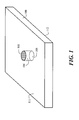
- FIG. 1 shows a top perspective view of a first exemplary body 100 in which the valve of the present invention can be used.
- Body 100 has a first flat surface 111, an opposing second flat surface 112, and a hole 104 that passes through body 100.
- Hole 104 intersects first surface 111 at orifice 105, and hole 104 intersects second surface 112 at orifice 106.
- a bottom perspective view of body 100 would look similar to the top perspective view of FIG. 1 .
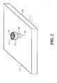
- FIG. 2 shows a bottom perspective view of a second exemplary body 120 in which the valve of the present invention can be used.
- Body 120 has a first flat surface 111, an opposing second surface 112, a tubular portion 122 extending from second surface 112, and a hole 104 that passes through both the thickness of body 120 and also through tubular portion 122.
- Tubular portion 122 terminates at rim 124 and orifice 126.
- Orifice 105 is the intersection of hole 104 and first surface 111, while orifice 126 is the termination of hole 104 at tubular portion 122.
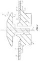
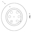
- the valve 10 of the present invention shown in the exemplary embodiments of FIGS. 3 - 7 comprises a stem 11 and a cap 20.
- the stem 11 includes a first sealing portion 12, and cap 20 includes a deformable lip 22.
- a first sealing portion 12 of valve 10 prevents leakage of a fluid through the orifice when the valve is in a closed state.
- the stem 11 is substantially straight (i.e., a substantially right-circular cylindrical stem) having one end attached to the first sealing portion 12 and the other end attached to a cap 20.
- the first sealing portion 12 extends radially from the stem 11.
- the first sealing portion 12 extends radially from the stem 11 and is more rigid than the deformable lip 22.
- the first sealing portion 12, extending radially from the stem 11 can be made more rigid than the deformable lip 22 by modifying the properties of the elastomer in the respective portions of the valve 10.
- the first sealing portion 12 can also be attached to the stem 11 and can be formed from a relatively non-deformable material when compared to the stem and deformable lip 22.
- the first sealing portion 12 extending radially from the stem 11 can have a geometry that makes the member more rigid than the deformable lip 22.
- the first sealing portion 12 can have one or more ridges, tapers, threads or other geometric shapes that render the stem 11 more rigid than the deformable lip 22.
- first sealing portion 12 includes tapered surface 15 that increases rigidity (compared to valves that don't have a tapered surface) and facilitates insertion of valve 10 through hole 104.
- the first sealing portion 12 has a diameter that is greater than the diameter of the stem 11 and the diameter of the first sealing portion 12 is less than the diameter of the deformable lip 22.
- the stem 11 of the valve 10 has a longitudinal axis 13 along which the stem can be displaced in order to actuate fluid flow through the valve.
- the stem 11 can include at least one passageway 30 extending through an interior of the stem and having a first opening 31 in the side of the stem and a second opening 32 in the cap 20 as exemplified by FIG. 3 .
- the second opening 32 in the cap 20 can be located on any portion of the cap which allows fluid to flow through the cap and can be on the bottom or side of the cap.
- the first opening 31 in the side of the stem 11 is typically located at a distance below the first sealing portion 12 such that no liquid can flow through the orifice unless the stem is displaced along the longitudinal axis 13. This ensures that no fluid can leak past the first sealing portion 12.
- the first opening 31 in the side of the stem 11 is typically located at a distance above the cap 20 such that when the stem is displaced along the longitudinal axis 13 the first opening 31 in the side of the stem is displaced to a position at or above the orifice. This allows unobstructed open fluid communication through the valve 10 in either direction through the at least one passageway 30.
- the at least one passageway 30 can be spaced apart in any arrangement about the stem 11 and more than one passageway can be present each having a first and second opening 31 and 32 usable to allow fluid flow through the valve 10.
- the valve 10 of the present invention includes a cap 20 that is connected to the stem 11.
- the cap 20 can be made from the list of elastomeric materials above, or other suitable materials, and typically the cap is more deformable than the first sealing portion 12 of the stem 11 by material selection or geometry.
- the cap 20 can also be made from a relatively non-deformable material and can be made from the same material as the rigid first sealing portion 12.
- the cap 20 includes a deformable lip 22 extending from the periphery of the cap. In one embodiment, the deformable lip 22 extends radially from the periphery of the cap 20.
- the deformable lip 22 can seat against the surfaces 111 or 112 of the body 100 or 120 and can act to hold the valve 10 in place while the valve is in a closed state.
- the diameter of the deformable lip 22 is greater than the diameter of the first sealing portion 12.
- the deformable lip 22 includes a second sealing portion 23.
- the second sealing portion 23 can be an upper or lower portion of the deformable lip 22 and will depend on the geometry of the orifices which are to be sealed by the valve.
- FIG. 3 corresponding to a body of the type shown in FIG. 1 (which can be, for example, a wall of a container), the sealing surface 14 of first sealing portion 12 seals against top surface 111 around orifice 105 in body 100.
- Second sealing portion 23 is located along the top surface of the lip 22 and is not sealingly engaged in FIG. 3 .
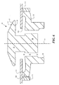
- the sealing surface 14 of first sealing portion 12 moves away from surface 111 of body 100 so that it is no longer sealed, while the second sealing portion 23 forms a tight seal between an inner surface of the deformable lip 22 and surface 112 of body 100 around orifice 106.
- the displacement of the stem 11 relative to the deformable lip 22 simultaneously opens the first sealing portion 12 and closes the second sealing portion 23 thereby allowing open fluid flow through the at least one passageway 30 and the orifice.
- the displacement of the stem 11 relative to the deformable lip 22 creates a restoring force against the axial displacement of the stem such that when the displacement force is removed the restoring force acts to close the first sealing portion 12 and open the second sealing portion 23 thereby returning the valve to the original closed position.
- the deformable lip 22 can also include a second sealing portion 23 which is located on the bottom of the deformable lip as exemplified by FIG. 5 .
- the second sealing portion 23 forms a tight seal between an outer surface of the deformable lip and the inside of tubular portion 122.
- tubular portion 122 extends outwardly from surface 112 of body 120.
- the cap 20 can include at least one passageway 30 extending through an interior of the cap and having a first opening 31 in the top of the cap and a second opening 32 in the bottom or side of the cap.
- the at least one passageway 30 is located at a distance from the center of the cap 20 that is less than the distance from the center of the stem 11 to the outermost distance of the first sealing portion 12. This arrangement allows for optimal fluid flow through the passageway 30 once the stem 11 is displaced along the longitudinal axis 13. However, other arrangements are permitted depending on the specific applications contemplated.
- the cap 20 can include a third sealing portion 40.
- the third sealing portion 40 is spaced apart from the second sealing portion 23 and is engageable when during axial displacement of the stem 11 relative to the deformable lip 22.
- the third sealing portion 40 is formed on a bottom portion of the cap 20 (as in FIGS. 3 and 4 ).
- the third sealing portion 40 can protrude from the bottom of the cap 20 and form a surface (as in FIGS. 5 and 6 ) that can seal against the outer circumference of a tube or pipe (not shown) that is capable of transferring fluid to or from the valve 10.
- Alternative sealing portions, such as one or more grooves, threads or depressions machined into the cap 20 could serve to engage the means for axial displacement.
- Axial displacement of the stem 11 along the longitudinal axis 13 relative to the deformable lip 22 of the cap 20 can be accomplished by any means that does not impede the basic function of the valve 10.
- Axial displacement of the stem 11 can be accomplished by a pulling force on the top of the stem. This allows for arrangements where a connection is attached to, or part of the stem 11 itself.
- the axial displacement of the stem 11 can be accomplished by pushing from the bottom of the cap 20.
- a tube, pipe or other conduit can directly interface to the third sealing portion 40 or an intermediate component such as a spring or mechanical actuator can interface at the bottom portion of the cap 20.
- axial displacement of the stem 11 can also be accomplished by a substantial fluid pressure at the bottom portion of the cap 20 in the direction of the stem.
- FIGS. 3 and 5 exemplify an embodiment of the present invention where the valve 10 is seated in an orifice that defines a container useful as an ink cartridge in an inkjet printer.
- the hole 104 exemplifies a supply port in the wall of an inkjet cartridge useful for providing ink from the cartridge to the printhead component of the printer.
- FIGS. 3 and 5 exemplify the condition where the ink cartridge is not connected to the printer. In this condition, the valve 10 is in a closed position and prevents leakage of ink from the cartridge during storage and shipping.
- FIGS. 3 and 5 exemplify an embodiment of the present invention where the valve 10 is seated in an orifice that defines a container useful as an ink cartridge in an inkjet printer.
- the hole 104 exemplifies a supply port in the wall of an inkjet cartridge useful for providing ink from the cartridge to the printhead component of the printer.
- FIGS. 3 and 5 exemplify the condition where the ink cartridge
- the ink cartridge comprising the valve 10 is connected to a component of the printer which axially displaces the stem 11 relative to the deformable lip 22 along the longitudinal axis 13, such as a supply conduit to an inkjet printhead.
- a component of the printer which axially displaces the stem 11 relative to the deformable lip 22 along the longitudinal axis 13, such as a supply conduit to an inkjet printhead.
- This provides a condition where ink stored in the ink cartridge can readily flow through the at least one passageway 30 of the valve 10 and through the orifice thereby providing an efficient means of delivering ink from the cartridge to the printhead. Removal of the ink cartridge from the supply conduit allows the restoring force, actuated by the axial displacement of the stem 11 relative to the deformable lip 22, to close the valve 10.
Landscapes
- Engineering & Computer Science (AREA)
- General Engineering & Computer Science (AREA)
- Mechanical Engineering (AREA)
- Lift Valve (AREA)
- Containers And Packaging Bodies Having A Special Means To Remove Contents (AREA)
- Closures For Containers (AREA)
- Ink Jet (AREA)
- Check Valves (AREA)
Applications Claiming Priority (2)
| Application Number | Priority Date | Filing Date | Title |
|---|---|---|---|
| US12/040,048 US8083332B2 (en) | 2008-02-29 | 2008-02-29 | Dual seating quick connect valve |
| PCT/US2009/001079 WO2009110964A2 (en) | 2008-02-29 | 2009-02-20 | Dual seating quick connect valve |
Publications (2)
| Publication Number | Publication Date |
|---|---|
| EP2250410A2 EP2250410A2 (en) | 2010-11-17 |
| EP2250410B1 true EP2250410B1 (en) | 2014-12-24 |
Family
ID=41012864
Family Applications (1)
| Application Number | Title | Priority Date | Filing Date |
|---|---|---|---|
| EP20090716382 Not-in-force EP2250410B1 (en) | 2008-02-29 | 2009-02-20 | Dual seating quick connect valve |
Country Status (5)
| Country | Link |
|---|---|
| US (1) | US8083332B2 (enExample) |
| EP (1) | EP2250410B1 (enExample) |
| JP (1) | JP5643115B2 (enExample) |
| TW (1) | TW201000321A (enExample) |
| WO (1) | WO2009110964A2 (enExample) |
Families Citing this family (16)
| Publication number | Priority date | Publication date | Assignee | Title |
|---|---|---|---|---|
| CA2546434C (en) | 2003-11-20 | 2013-01-22 | The Henry M. Jackson Foundation For The Advancement Of Military Medicine , Inc. | Portable hand pump for evacuation of fluids |
| US8337475B2 (en) | 2004-10-12 | 2012-12-25 | C. R. Bard, Inc. | Corporeal drainage system |
| WO2007038643A1 (en) | 2005-09-26 | 2007-04-05 | C.R. Bard, Inc. | Catheter connection systems |
| US20110025766A1 (en) | 2009-07-31 | 2011-02-03 | Silverbrook Research Pty Ltd | Wide format printer with adjustable aerosol collection |
| US20110279592A1 (en) | 2010-05-17 | 2011-11-17 | Silverbrook Research Pty Ltd | Liquid container with capacity state sensing |
| US20110279531A1 (en) | 2010-05-17 | 2011-11-17 | Silverbrook Research Pty Ltd | Maintenance apparatus having cleaner for rotatable wiper |
| JP5776148B2 (ja) * | 2010-08-18 | 2015-09-09 | 株式会社リコー | 画像形成装置 |
| US20130291787A1 (en) * | 2012-05-02 | 2013-11-07 | Gene P. Broussard, Jr. | Illuminated Emergency Notification Balloon |
| CN102829316B (zh) * | 2012-09-10 | 2015-09-02 | 郑州奥特科技有限公司 | 一种液体分配阀 |
| US9347578B2 (en) * | 2012-11-08 | 2016-05-24 | Parker-Hannifin Corporation | Check valve assembly |
| US9896592B2 (en) * | 2014-11-21 | 2018-02-20 | Vernay Laboratories, Inc. | Temporary elastomeric functional barrier membrane and method of manufacture |
| US10702281B2 (en) | 2016-07-18 | 2020-07-07 | Merit Medical Systems, Inc. | Inflatable radial artery compression device |
| CN110891794B (zh) * | 2017-09-21 | 2021-11-16 | 惠普深蓝有限责任公司 | 打印试剂供应单元阀 |
| WO2021188092A1 (en) * | 2020-03-17 | 2021-09-23 | Aptargroup, Inc. | Valve |
| CN116113373A (zh) | 2020-08-13 | 2023-05-12 | 美国医疗设备有限公司 | 具有束紧腕带的可充气桡动脉压迫装置和使用方法 |
| US12426864B2 (en) | 2021-06-18 | 2025-09-30 | Merit Medical Systems, Inc. | Hemostasis devices and methods of use |
Family Cites Families (18)
| Publication number | Priority date | Publication date | Assignee | Title |
|---|---|---|---|---|
| US3779276A (en) * | 1972-06-09 | 1973-12-18 | L King | Drainage valve structure |
| US3941149A (en) * | 1974-11-11 | 1976-03-02 | Baxter Laboratories, Inc. | Valve |
| US4677447A (en) * | 1986-03-20 | 1987-06-30 | Hewlett-Packard Company | Ink jet printhead having a preloaded check valve |
| JPH083784Y2 (ja) * | 1989-08-09 | 1996-01-31 | トヨタ自動車株式会社 | チェック弁装置 |
| US5067449A (en) * | 1991-04-12 | 1991-11-26 | Tecumseh Products Company | Fitted crankcase breather valve assembly |
| JPH08174860A (ja) * | 1994-10-26 | 1996-07-09 | Seiko Epson Corp | インクジェットプリンタ用インクカートリッジ |
| JPH0932943A (ja) * | 1995-07-21 | 1997-02-07 | Fujikura Rubber Ltd | アンブレラバルブ |
| US6039441A (en) * | 1995-09-28 | 2000-03-21 | Fuji Xerox Co., Ltd. | Ink jet recording unit |
| GB9613077D0 (en) * | 1996-06-21 | 1996-08-28 | Mangar International Ltd | Pneumatically inflatable lifting devices and valve assemblies for lifting such devices |
| JP3795584B2 (ja) * | 1996-07-15 | 2006-07-12 | トーステ株式会社 | 二重シール弁 |
| US5842682A (en) * | 1996-11-26 | 1998-12-01 | The Procter & Gamble Company | Non-leaking, non-venting liquid filled canister quick disconnect system |
| ES2153174T3 (es) * | 1997-12-09 | 2001-02-16 | Sporting S A | Valvula universal. |
| JP4193435B2 (ja) * | 2002-07-23 | 2008-12-10 | ブラザー工業株式会社 | インクカートリッジ、および、そのインク充填方法 |
| US6651955B2 (en) * | 2001-07-30 | 2003-11-25 | Hewlett-Packard Development Company, L.P. | Elastomeric valve, and methods |
| JP3991853B2 (ja) * | 2002-09-12 | 2007-10-17 | セイコーエプソン株式会社 | インクカートリッジ |
| US7082967B2 (en) * | 2004-01-05 | 2006-08-01 | Engineered Products & Services, Inc. | Modular umbrella valve |
| US7302971B2 (en) * | 2004-12-22 | 2007-12-04 | Vernay Laboratories, Inc. | Umbrella valve and assembly |
| US7726335B2 (en) * | 2005-04-29 | 2010-06-01 | Ti Group Automotive Systems, L.L.C. | Check valve apparatus for fuel delivery systems |
-
2008
- 2008-02-29 US US12/040,048 patent/US8083332B2/en not_active Expired - Fee Related
-
2009
- 2009-02-20 EP EP20090716382 patent/EP2250410B1/en not_active Not-in-force
- 2009-02-20 JP JP2010548679A patent/JP5643115B2/ja not_active Expired - Fee Related
- 2009-02-20 WO PCT/US2009/001079 patent/WO2009110964A2/en not_active Ceased
- 2009-02-27 TW TW98106519A patent/TW201000321A/zh unknown
Also Published As
| Publication number | Publication date |
|---|---|
| EP2250410A2 (en) | 2010-11-17 |
| US8083332B2 (en) | 2011-12-27 |
| US20090219353A1 (en) | 2009-09-03 |
| WO2009110964A2 (en) | 2009-09-11 |
| JP2011519402A (ja) | 2011-07-07 |
| TW201000321A (en) | 2010-01-01 |
| JP5643115B2 (ja) | 2014-12-17 |
| WO2009110964A3 (en) | 2010-06-10 |
Similar Documents
| Publication | Publication Date | Title |
|---|---|---|
| EP2250410B1 (en) | Dual seating quick connect valve | |
| CN111720580B (zh) | 流体控制阀 | |
| CN101842257A (zh) | 加注管嘴定位装置 | |
| US9133942B2 (en) | Valve structure for fluid pressure device | |
| US20180134147A1 (en) | Filling device | |
| KR19990006673A (ko) | 압연 다이어프램 포핏을 가지는 소형 밸브 | |
| US20170189665A1 (en) | Medical connector | |
| JP6510839B2 (ja) | 樹脂製給油口 | |
| EP1192101B1 (en) | Coupling with valves | |
| CN101918721A (zh) | 堵塞排放阀组件 | |
| EP4530512A2 (en) | Valves with integrated orifice restrictions | |
| EP1864042A2 (en) | Valve for withdrawal of a substance from a container | |
| US20050127113A1 (en) | Blocking element for use in a valve for a non-refillable pressurized container | |
| US12090837B2 (en) | Over-fueling prevention valve | |
| JP7122034B1 (ja) | 連結システム及び逆止弁 | |
| EP4015884B1 (en) | Venting valve | |
| JP2008062878A (ja) | 燃料タンク装着部品 | |
| JP2004232472A (ja) | パルセーションダンパのフェール時漏れ防止機構 |
Legal Events
| Date | Code | Title | Description |
|---|---|---|---|
| PUAI | Public reference made under article 153(3) epc to a published international application that has entered the european phase |
Free format text: ORIGINAL CODE: 0009012 |
|
| 17P | Request for examination filed |
Effective date: 20100903 |
|
| AK | Designated contracting states |
Kind code of ref document: A2 Designated state(s): AT BE BG CH CY CZ DE DK EE ES FI FR GB GR HR HU IE IS IT LI LT LU LV MC MK MT NL NO PL PT RO SE SI SK TR |
|
| AX | Request for extension of the european patent |
Extension state: AL BA RS |
|
| DAX | Request for extension of the european patent (deleted) | ||
| REG | Reference to a national code |
Ref country code: DE Ref legal event code: R079 Ref document number: 602009028541 Country of ref document: DE Free format text: PREVIOUS MAIN CLASS: F16K0015140000 Ipc: B41J0002175000 |
|
| GRAP | Despatch of communication of intention to grant a patent |
Free format text: ORIGINAL CODE: EPIDOSNIGR1 |
|
| RIC1 | Information provided on ipc code assigned before grant |
Ipc: F16K 15/14 20060101ALI20140731BHEP Ipc: B41J 2/175 20060101AFI20140731BHEP |
|
| INTG | Intention to grant announced |
Effective date: 20140812 |
|
| GRAS | Grant fee paid |
Free format text: ORIGINAL CODE: EPIDOSNIGR3 |
|
| GRAA | (expected) grant |
Free format text: ORIGINAL CODE: 0009210 |
|
| AK | Designated contracting states |
Kind code of ref document: B1 Designated state(s): AT BE BG CH CY CZ DE DK EE ES FI FR GB GR HR HU IE IS IT LI LT LU LV MC MK MT NL NO PL PT RO SE SI SK TR |
|
| REG | Reference to a national code |
Ref country code: GB Ref legal event code: FG4D |
|
| REG | Reference to a national code |
Ref country code: CH Ref legal event code: EP |
|
| REG | Reference to a national code |
Ref country code: IE Ref legal event code: FG4D |
|
| REG | Reference to a national code |
Ref country code: AT Ref legal event code: REF Ref document number: 702929 Country of ref document: AT Kind code of ref document: T Effective date: 20150115 |
|
| REG | Reference to a national code |
Ref country code: DE Ref legal event code: R096 Ref document number: 602009028541 Country of ref document: DE Effective date: 20150212 |
|
| REG | Reference to a national code |
Ref country code: NL Ref legal event code: VDEP Effective date: 20141224 |
|
| PG25 | Lapsed in a contracting state [announced via postgrant information from national office to epo] |
Ref country code: FI Free format text: LAPSE BECAUSE OF FAILURE TO SUBMIT A TRANSLATION OF THE DESCRIPTION OR TO PAY THE FEE WITHIN THE PRESCRIBED TIME-LIMIT Effective date: 20141224 Ref country code: NO Free format text: LAPSE BECAUSE OF FAILURE TO SUBMIT A TRANSLATION OF THE DESCRIPTION OR TO PAY THE FEE WITHIN THE PRESCRIBED TIME-LIMIT Effective date: 20150324 Ref country code: LT Free format text: LAPSE BECAUSE OF FAILURE TO SUBMIT A TRANSLATION OF THE DESCRIPTION OR TO PAY THE FEE WITHIN THE PRESCRIBED TIME-LIMIT Effective date: 20141224 |
|
| REG | Reference to a national code |
Ref country code: LT Ref legal event code: MG4D |
|
| PG25 | Lapsed in a contracting state [announced via postgrant information from national office to epo] |
Ref country code: HR Free format text: LAPSE BECAUSE OF FAILURE TO SUBMIT A TRANSLATION OF THE DESCRIPTION OR TO PAY THE FEE WITHIN THE PRESCRIBED TIME-LIMIT Effective date: 20141224 Ref country code: SE Free format text: LAPSE BECAUSE OF FAILURE TO SUBMIT A TRANSLATION OF THE DESCRIPTION OR TO PAY THE FEE WITHIN THE PRESCRIBED TIME-LIMIT Effective date: 20141224 Ref country code: GR Free format text: LAPSE BECAUSE OF FAILURE TO SUBMIT A TRANSLATION OF THE DESCRIPTION OR TO PAY THE FEE WITHIN THE PRESCRIBED TIME-LIMIT Effective date: 20150325 Ref country code: LV Free format text: LAPSE BECAUSE OF FAILURE TO SUBMIT A TRANSLATION OF THE DESCRIPTION OR TO PAY THE FEE WITHIN THE PRESCRIBED TIME-LIMIT Effective date: 20141224 |
|
| REG | Reference to a national code |
Ref country code: AT Ref legal event code: MK05 Ref document number: 702929 Country of ref document: AT Kind code of ref document: T Effective date: 20141224 |
|
| PG25 | Lapsed in a contracting state [announced via postgrant information from national office to epo] |
Ref country code: NL Free format text: LAPSE BECAUSE OF FAILURE TO SUBMIT A TRANSLATION OF THE DESCRIPTION OR TO PAY THE FEE WITHIN THE PRESCRIBED TIME-LIMIT Effective date: 20141224 |
|
| PG25 | Lapsed in a contracting state [announced via postgrant information from national office to epo] |
Ref country code: SK Free format text: LAPSE BECAUSE OF FAILURE TO SUBMIT A TRANSLATION OF THE DESCRIPTION OR TO PAY THE FEE WITHIN THE PRESCRIBED TIME-LIMIT Effective date: 20141224 Ref country code: CZ Free format text: LAPSE BECAUSE OF FAILURE TO SUBMIT A TRANSLATION OF THE DESCRIPTION OR TO PAY THE FEE WITHIN THE PRESCRIBED TIME-LIMIT Effective date: 20141224 Ref country code: EE Free format text: LAPSE BECAUSE OF FAILURE TO SUBMIT A TRANSLATION OF THE DESCRIPTION OR TO PAY THE FEE WITHIN THE PRESCRIBED TIME-LIMIT Effective date: 20141224 Ref country code: ES Free format text: LAPSE BECAUSE OF FAILURE TO SUBMIT A TRANSLATION OF THE DESCRIPTION OR TO PAY THE FEE WITHIN THE PRESCRIBED TIME-LIMIT Effective date: 20141224 Ref country code: RO Free format text: LAPSE BECAUSE OF FAILURE TO SUBMIT A TRANSLATION OF THE DESCRIPTION OR TO PAY THE FEE WITHIN THE PRESCRIBED TIME-LIMIT Effective date: 20141224 |
|
| PG25 | Lapsed in a contracting state [announced via postgrant information from national office to epo] |
Ref country code: IS Free format text: LAPSE BECAUSE OF FAILURE TO SUBMIT A TRANSLATION OF THE DESCRIPTION OR TO PAY THE FEE WITHIN THE PRESCRIBED TIME-LIMIT Effective date: 20150424 Ref country code: PL Free format text: LAPSE BECAUSE OF FAILURE TO SUBMIT A TRANSLATION OF THE DESCRIPTION OR TO PAY THE FEE WITHIN THE PRESCRIBED TIME-LIMIT Effective date: 20141224 Ref country code: AT Free format text: LAPSE BECAUSE OF FAILURE TO SUBMIT A TRANSLATION OF THE DESCRIPTION OR TO PAY THE FEE WITHIN THE PRESCRIBED TIME-LIMIT Effective date: 20141224 |
|
| REG | Reference to a national code |
Ref country code: DE Ref legal event code: R119 Ref document number: 602009028541 Country of ref document: DE |
|
| PG25 | Lapsed in a contracting state [announced via postgrant information from national office to epo] |
Ref country code: LU Free format text: LAPSE BECAUSE OF FAILURE TO SUBMIT A TRANSLATION OF THE DESCRIPTION OR TO PAY THE FEE WITHIN THE PRESCRIBED TIME-LIMIT Effective date: 20150220 |
|
| REG | Reference to a national code |
Ref country code: CH Ref legal event code: PL |
|
| PG25 | Lapsed in a contracting state [announced via postgrant information from national office to epo] |
Ref country code: LI Free format text: LAPSE BECAUSE OF NON-PAYMENT OF DUE FEES Effective date: 20150228 Ref country code: CH Free format text: LAPSE BECAUSE OF NON-PAYMENT OF DUE FEES Effective date: 20150228 Ref country code: DK Free format text: LAPSE BECAUSE OF FAILURE TO SUBMIT A TRANSLATION OF THE DESCRIPTION OR TO PAY THE FEE WITHIN THE PRESCRIBED TIME-LIMIT Effective date: 20141224 Ref country code: MC Free format text: LAPSE BECAUSE OF FAILURE TO SUBMIT A TRANSLATION OF THE DESCRIPTION OR TO PAY THE FEE WITHIN THE PRESCRIBED TIME-LIMIT Effective date: 20141224 |
|
| PLBE | No opposition filed within time limit |
Free format text: ORIGINAL CODE: 0009261 |
|
| STAA | Information on the status of an ep patent application or granted ep patent |
Free format text: STATUS: NO OPPOSITION FILED WITHIN TIME LIMIT |
|
| REG | Reference to a national code |
Ref country code: IE Ref legal event code: MM4A |
|
| GBPC | Gb: european patent ceased through non-payment of renewal fee |
Effective date: 20150324 |
|
| REG | Reference to a national code |
Ref country code: FR Ref legal event code: ST Effective date: 20151030 |
|
| 26N | No opposition filed |
Effective date: 20150925 |
|
| PG25 | Lapsed in a contracting state [announced via postgrant information from national office to epo] |
Ref country code: IT Free format text: LAPSE BECAUSE OF FAILURE TO SUBMIT A TRANSLATION OF THE DESCRIPTION OR TO PAY THE FEE WITHIN THE PRESCRIBED TIME-LIMIT Effective date: 20141224 |
|
| PG25 | Lapsed in a contracting state [announced via postgrant information from national office to epo] |
Ref country code: DE Free format text: LAPSE BECAUSE OF NON-PAYMENT OF DUE FEES Effective date: 20150901 Ref country code: GB Free format text: LAPSE BECAUSE OF NON-PAYMENT OF DUE FEES Effective date: 20150324 Ref country code: IE Free format text: LAPSE BECAUSE OF NON-PAYMENT OF DUE FEES Effective date: 20150220 |
|
| PG25 | Lapsed in a contracting state [announced via postgrant information from national office to epo] |
Ref country code: SI Free format text: LAPSE BECAUSE OF FAILURE TO SUBMIT A TRANSLATION OF THE DESCRIPTION OR TO PAY THE FEE WITHIN THE PRESCRIBED TIME-LIMIT Effective date: 20141224 Ref country code: FR Free format text: LAPSE BECAUSE OF NON-PAYMENT OF DUE FEES Effective date: 20150302 |
|
| PG25 | Lapsed in a contracting state [announced via postgrant information from national office to epo] |
Ref country code: BE Free format text: LAPSE BECAUSE OF FAILURE TO SUBMIT A TRANSLATION OF THE DESCRIPTION OR TO PAY THE FEE WITHIN THE PRESCRIBED TIME-LIMIT Effective date: 20141224 |
|
| PG25 | Lapsed in a contracting state [announced via postgrant information from national office to epo] |
Ref country code: MT Free format text: LAPSE BECAUSE OF FAILURE TO SUBMIT A TRANSLATION OF THE DESCRIPTION OR TO PAY THE FEE WITHIN THE PRESCRIBED TIME-LIMIT Effective date: 20141224 |
|
| PG25 | Lapsed in a contracting state [announced via postgrant information from national office to epo] |
Ref country code: HU Free format text: LAPSE BECAUSE OF FAILURE TO SUBMIT A TRANSLATION OF THE DESCRIPTION OR TO PAY THE FEE WITHIN THE PRESCRIBED TIME-LIMIT; INVALID AB INITIO Effective date: 20090220 Ref country code: BG Free format text: LAPSE BECAUSE OF FAILURE TO SUBMIT A TRANSLATION OF THE DESCRIPTION OR TO PAY THE FEE WITHIN THE PRESCRIBED TIME-LIMIT Effective date: 20141224 |
|
| PG25 | Lapsed in a contracting state [announced via postgrant information from national office to epo] |
Ref country code: CY Free format text: LAPSE BECAUSE OF FAILURE TO SUBMIT A TRANSLATION OF THE DESCRIPTION OR TO PAY THE FEE WITHIN THE PRESCRIBED TIME-LIMIT Effective date: 20141224 |
|
| PG25 | Lapsed in a contracting state [announced via postgrant information from national office to epo] |
Ref country code: PT Free format text: LAPSE BECAUSE OF FAILURE TO SUBMIT A TRANSLATION OF THE DESCRIPTION OR TO PAY THE FEE WITHIN THE PRESCRIBED TIME-LIMIT Effective date: 20150424 |
|
| PG25 | Lapsed in a contracting state [announced via postgrant information from national office to epo] |
Ref country code: TR Free format text: LAPSE BECAUSE OF FAILURE TO SUBMIT A TRANSLATION OF THE DESCRIPTION OR TO PAY THE FEE WITHIN THE PRESCRIBED TIME-LIMIT Effective date: 20141224 |
|
| PG25 | Lapsed in a contracting state [announced via postgrant information from national office to epo] |
Ref country code: MK Free format text: LAPSE BECAUSE OF FAILURE TO SUBMIT A TRANSLATION OF THE DESCRIPTION OR TO PAY THE FEE WITHIN THE PRESCRIBED TIME-LIMIT Effective date: 20141224 |