EP2250399B1 - Ventilkappe für ein rückschlagventil - Google Patents
Ventilkappe für ein rückschlagventil Download PDFInfo
- Publication number
- EP2250399B1 EP2250399B1 EP08872977.7A EP08872977A EP2250399B1 EP 2250399 B1 EP2250399 B1 EP 2250399B1 EP 08872977 A EP08872977 A EP 08872977A EP 2250399 B1 EP2250399 B1 EP 2250399B1
- Authority
- EP
- European Patent Office
- Prior art keywords
- valve
- check valve
- section
- flow cross
- cap
- Prior art date
- Legal status (The legal status is an assumption and is not a legal conclusion. Google has not performed a legal analysis and makes no representation as to the accuracy of the status listed.)
- Not-in-force
Links
Images


Classifications
-
- F—MECHANICAL ENGINEERING; LIGHTING; HEATING; WEAPONS; BLASTING
- F16—ENGINEERING ELEMENTS AND UNITS; GENERAL MEASURES FOR PRODUCING AND MAINTAINING EFFECTIVE FUNCTIONING OF MACHINES OR INSTALLATIONS; THERMAL INSULATION IN GENERAL
- F16H—GEARING
- F16H7/00—Gearings for conveying rotary motion by endless flexible members
- F16H7/08—Means for varying tension of belts, ropes or chains
- F16H7/0829—Means for varying tension of belts, ropes or chains with vibration damping means
- F16H7/0836—Means for varying tension of belts, ropes or chains with vibration damping means of the fluid and restriction type, e.g. dashpot
-
- F—MECHANICAL ENGINEERING; LIGHTING; HEATING; WEAPONS; BLASTING
- F16—ENGINEERING ELEMENTS AND UNITS; GENERAL MEASURES FOR PRODUCING AND MAINTAINING EFFECTIVE FUNCTIONING OF MACHINES OR INSTALLATIONS; THERMAL INSULATION IN GENERAL
- F16H—GEARING
- F16H7/00—Gearings for conveying rotary motion by endless flexible members
- F16H7/08—Means for varying tension of belts, ropes or chains
- F16H7/0848—Means for varying tension of belts, ropes or chains with means for impeding reverse motion
-
- F—MECHANICAL ENGINEERING; LIGHTING; HEATING; WEAPONS; BLASTING
- F16—ENGINEERING ELEMENTS AND UNITS; GENERAL MEASURES FOR PRODUCING AND MAINTAINING EFFECTIVE FUNCTIONING OF MACHINES OR INSTALLATIONS; THERMAL INSULATION IN GENERAL
- F16H—GEARING
- F16H7/00—Gearings for conveying rotary motion by endless flexible members
- F16H7/08—Means for varying tension of belts, ropes or chains
- F16H2007/0802—Actuators for final output members
- F16H2007/0806—Compression coil springs
-
- F—MECHANICAL ENGINEERING; LIGHTING; HEATING; WEAPONS; BLASTING
- F16—ENGINEERING ELEMENTS AND UNITS; GENERAL MEASURES FOR PRODUCING AND MAINTAINING EFFECTIVE FUNCTIONING OF MACHINES OR INSTALLATIONS; THERMAL INSULATION IN GENERAL
- F16H—GEARING
- F16H7/00—Gearings for conveying rotary motion by endless flexible members
- F16H7/08—Means for varying tension of belts, ropes or chains
- F16H7/0848—Means for varying tension of belts, ropes or chains with means for impeding reverse motion
- F16H2007/0859—Check valves
Definitions
- the present invention relates to a check valve for a hydraulic tensioning system of traction mechanism drives of an internal combustion engine according to the preamble of claim 1 and as it is known from JP 2003026657 A is known.
- a check valve for a hydraulic tensioning system of traction mechanism drives of an internal combustion engine according to the preamble of claim 1 and as it is known from JP 2003026657 A is known.
- the construction of the check valve comprises a housing, also referred to as a valve cap or retaining means, in which, in particular, a valve body designed as a ball is used, which is spring-loaded with a flow cross-section in the connection.
- a hydraulic clamping system for traction drives in particular chain drives an internal combustion engine known.
- a clamping piston pressed against the traction means is received longitudinally displaceably in a cylinder.
- the tensioning piston and the cylinder define a pressure space for receiving a hydraulic fluid.
- a movement of the clamping piston in the direction of the traction means which can also be referred to as the expansion phase, causes an enlargement of the pressure chamber, wherein due to a self-adjusting negative pressure opens a check valve, wherein hydraulic fluid can flow into the pressure chamber.
- a check valve construction in which the ball valve designed as a body cooperates with a centrally formed as a bore valve seat in the housing or the valve cap.
- the known check valves show a structure in which the valve body by a relatively narrow adjusting gap between the formed as a ball valve body and the housing or the valve cap and by adjusting itself behind the valve body by the valve spring flow control effective closing at the beginning of the Compression phase is delayed.
- valve cap has a central flow cross-section is closed with complete flow cross section of the valve through the valve body, the ball, wherein between the valve spring, the valve cap and the ball, a space forms, which also causes a hydraulic adhesion because the hydraulic fluid can not flow freely due to the sealing by the valve body and also obstructed by the valve body spring.
- the invention has for its object to provide a funktionsverêttes check valve with a reduced flow resistance, to achieve an optimum Nachströmung the hydraulic fluid.
- the check valve according to the invention used in hydraulic clamping systems ensures in the open position, a rapid and delay-free Nachströmung the hydraulic fluid from the reservoir into the pressure chamber. This results in an improved suction of the hydraulic fluid in the expansion phase, which leads to an optimized switching behavior of the hydraulic valve.
- the inventive measure prevents adverse, hydraulic adhesion of the valve body to the valve seat of the housing, which leads to an improved hysteresis behavior in a reversal of the expansion phase in the compression phase.
- valve seat at the bottom of the housing which can also be referred to as a valve cap, is formed by a flow cross-section which does not form a positive connection with the valve body.
- the flow cross-sections in the bottom of the valve cap or the housing may be arbitrarily shaped geometrically, regardless of their design is not always a complete positive connection between the valve body and the flow cross-sectional valve seat adjusts.
- a preferred embodiment provides a non-circular, with the valve body cooperating flow cross-section.
- in the bottom of the valve cap an oval, polygonal, For example, introduce triangular or square shaped flow cross-section or a polygonal flow cross-section with rounded corners.
- a plurality of flow cross sections in the newly designed bottom of the housing or the valve cap.
- the position of these flow cross-sections is such that in an end position of the valve body at the valve seat of the bottom of the flow cross-sections of the flow cross-sections covers partially or in regions, so that an almost unhindered afterflow of hydraulic fluid is possible.
- the outer contour forms an isosceles triangle.
- the valve body is supported in an end position at a central ridge between the holes, whereby the hydraulic fluid flow is hardly affected in the expansion phase.
- Another embodiment of the invention provides to introduce the flow cross-section in a convex shaped portion of the bottom, wherein the radius of curvature of the bottom of the radius of the designed as a ball valve body differs.
- the radius of curvature of the bottom is greater than that of the valve body.
- a reverse design wherein the smaller designed radius of curvature of the bottom relative to that of the valve body is limited locally to a flow cross-sectional area, starting from which a larger valve body to the radius of curvature followed.
- the check valve according to the invention further includes a design in which the bottom is designed such that a contact surface associated with the valve body forms different curvatures with two cutting planes perpendicular to one another, each containing a movement axis of the valve body.
- FIG. 1 is a hydraulic clamping system 1 shown in a sectional view, which is associated with a traction mechanism and via an in FIG. 1 not shown tension roller interacts indirectly with a traction means of a traction mechanism drive.
- the structure comprises a housing 2, which is stationary via a fastening eye 3a and thereby pivotable, for example, is articulated on a housing of the internal combustion engine.
- the housing 2 forms a pot-shaped component in which a cylinder 4 is centrally inserted, which is intended to receive a linearly displaceable piston 5.
- the cylinder 4 in conjunction with the piston 5 define a filled with hydraulic fluid pressure chamber 6, via a channel 8 of the housing 2 and a flow area 12 of the cylinder 4 with a reservoir 9 for the hydraulic fluid connected is.
- the reservoir 9 is bounded on the outside by the housing 2 and inside of the lateral surface of the cylinder 4.
- a further integrated in the cylinder 4 compression spring 10 is supported with a spring end to a bottom of the housing 2 and with the other spring end to a fixed position on the piston 5 disc 11.
- the compression spring 10 acts on the piston 5 in the direction of a force "R” and causes an actuating movement of the piston 5 and thus a force application of a tensioning roller, which is connected to the fastening eye 3b.
- This also as expansion movement to be designated piston movement causes a negative pressure in the pressure chamber 6, whereby hydraulic fluid flows through the check valve 7, from the reservoir 9 through the channel 8 of the housing 2 and the flow area 12 of the cylinder 4 in the pressure chamber 6.
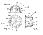
- FIGS. 2a-6c show variants of inventively designed check valves, which differ in particular by differently shaped flow cross sections in the bottom of the housing of the check valve.
- FIGS. 2a and 2b show in different views the check valve 16, in which the cup-shaped, to be designated as a valve cap housing 17 in the bottom 18 includes an oval, the valve seat 21 forming flow cross-section 19. Due to the oval shape of the flow cross-section 19, this is not completely closed by the designed as a ball valve body 20 in the end position. Thus, in the expansion phase, a subset of the hydraulic fluid flow through the check valve 16.
- the bottom 18 of the check valve 16 has a square-shaped flow cross-section 22, whereby also a valve seat 23 is adjusted, which is not completely closed by the adjacent valve body 20.
- FIGS. 4a, 4b refer to a polygonal flow cross-section 24 in the bottom 18 of the housing 17, which also does not allow complete positive engagement with the valve body 20.
- FIGS. 5a, 5b Another variant is in the FIGS. 5a, 5b shown, in which the check valve 16 as a flow cross-section 26 includes three identically dimensioned, introduced in an equilateral triangle in the bottom 18 bores, which together form a limited only by the valve body 20 valve seat 27 closable.
- FIG. 6a - 6c includes the check valve 16 a housing 17 with a bottom 18, which is designed so that a valve body 20 associated contact surface 31 comprises two mutually perpendicular cutting planes 32a, 32 b each forming a movement axis of the valve body 20 with mutually different curvatures.
- ⁇ B> reference number list ⁇ / b> 1 clamping system 2 casing 3a fastening eye 3b fastening eye 4 cylinder 5 piston 6 pressure chamber 7 check valve 8th channel 9 reservoir 10 compression spring 11 disc 12 flow cross-section 13 valve body 14 valve seat 15 leakage gap 16 check valve 17 casing 18 ground 19 Flow area 20 valve body 21 valve seat 22 Flow area 23 valve seat 24 Flow area 25 valve seat 26 Flow area 27 valve seat 28 Flow area 29 valve seat 30 clearance 31 contact area 32a cutting plane 32b cutting plane
Landscapes
- Engineering & Computer Science (AREA)
- General Engineering & Computer Science (AREA)
- Mechanical Engineering (AREA)
- Check Valves (AREA)
Description
- Die vorliegende Erfindung betrifft ein Rückschlagventil für ein hydraulisches Spannsystem von Zugmitteltrieben einer Brennkraftmaschine entsprechend dem Oberbegriff des Anspruchs 1 und wie es aus der
JP 2003026657 A - Aus der
DE 40 35 823 C1 ist ein hydraulisches Spannsystem für Zugmitteltriebe, insbesondere Kettentriebe einer Brennkraftmaschine bekannt. Ein gegen das Zugmittel angedrückter Spannkolben ist in einem Zylinder längsverschieblich aufgenommen. Der Spannkolben und der Zylinder begrenzen einen Druckraum, zur Aufnahme eines Hydraulikfluids. Eine Bewegung des Spannkolbens in Richtung des Zugmittels, die auch als Expansionsphase bezeichnet werden kann, bewirkt eine Vergrößerung des Druckraums, wobei infolge eines sich einstellenden Unterdrucks ein Rückschlagventil öffnet, wobei Hydraulikfluid in den Druckraum nachströmen kann. In der Kompressionsphase, bei auftretender Spannung des Zugmittels wird der Spannkolben entgegengesetzt, d.h. einwärts beaufschlagt, wobei sich der Druck im Druckraum vergrößert, mit der Folge, dass sich der Spannkolben einwärts bewegt, synchron zu einer angesteuerten Teilmenge des Hydraulikfluids über einen sich zwischen dem Spannkolben und dem Gehäuse einstellenden Leckspalt. In der Kompressionsphase unterbindet folglich das Rückschlagventil einen Rückfluss des Hydraulikfluids vom Druckraum in den Vorratsraum. Dieser bekannte Aufbau führt zu einem hydraulischen Anhaften des als Kugel ausgebildeten Ventilkörpers an dem Ventilsitz des Rückschlagventils. - Weiterhin ist ein Rückschlagventilaufbau bekannt, bei der der als Kugel gestaltete Ventilkörper mit einem zentrisch als Bohrung ausgebildeten Ventilsitz in dem Gehäuse bzw. der Ventilkappe zusammenwirkt. Übereinstimmend zeigen die bekannten Rückschlagventile einen Aufbau, bei dem der Ventilkörper durch einen relativ engen sich einstellenden Spalt zwischen dem als Kugel ausgebildeten Ventilkörper und dem Gehäuse bzw. der Ventilkappe und durch eine sich hinter dem Ventilkörper durch die Ventilfeder einstellende Strömungsbeeinflussung ein wirksames Schließen zu Beginn der Kompressionsphase verzögert ist.
- Bei einem Aufbau des Rückschlagventils, bei dem die Ventilkappe eine zentrische Strömungsquerschnitt aufweist wird diese bei vollständiger Strömungsquerschnitt des Ventils durch den Ventilkörper, die Kugel verschlossen, wobei zwischen der Ventilfeder, der Ventilkappe und der Kugel sich ein Raum bildet, der ebenso ein hydraulisches Anhaften bewirkt, da das Hydraulikfluid nicht ungehindert zuströmen kann, aufgrund der Abdichtung durch den Ventilkörper und außerdem durch die Ventilkörperfeder behindert ist.
- Der Erfindung liegt die Aufgabe zugrunde, ein funktionsverbessertes Rückschlagventil zu schaffen mit einem verminderten Strömungswiderstand, zur Erzielung einer optimalen Nachströmung des Hydraulikfluids.
- Zur Lösung dieser Problemstellung ist erfindungsgemäß ein Rückschlagventil mit den Merkmalen des Anspruchs 1 vorgesehen.
- . Das erfindungsgemäße, in hydraulischen Spannsystemen eingesetzte Rückschlagventil gewährleistet in der geöffneten Stellung eine schnelle und verzögerungsfreie Nachströmung des Hydraulikfluids aus dem Reservoir in den Druckraum. Damit stellt sich ein verbessertes Nachsaugen des Hydraulikfluids in der Expansionsphase ein, das zu einem optimierten Schaltverhalten des Hydraulikventils führt. Andererseits verhindert der Aufbau des erfindungsgemäßen Hydraulikventils in der Kompressionsphase eine Durchströmung des Hydraulikfluids. Außerdem verhindert die erfindungsgemäße Maßnahme ein nachteiliges, hydraulisches Anhaften des Ventilkörpers an dem Ventilsitz des Gehäuses, was bei einer Umkehrung von der Expansionsphase in die Kompressionsphase zu einem verbesserten Hystereseverhalten führt.
- Weitere vorteilhafte Ausgestaltungen der Erfindung sind Gegenstand der abhängigen Ansprüche 2-4.
- Der Ventilsitz am Boden des auch als Ventilkappe zu bezeichnenden Gehäuses wird durch einen Strömungsquerschnitt gebildet, der keinen Formschluss mit dem Ventilkörper eingeht. Dadurch kann selbst bei einem Anliegen des Ventilkörpers am Ventilsitz eine weitestgehend ungehinderte Nachströmung des Hydraulikfluids in den Druckraum erfolgen.
- Die Strömungsquerschnitte in dem Boden der Ventilkappe bzw. des Gehäuses können beliebig geometrisch geformt sein, wobei unabhängig von deren Gestaltung sich stets kein vollständiger Formschluss zwischen dem Ventilkörper und dem einen Strömungsquerschnitt bildenden Ventilsitz einstellt. Eine bevorzugte Gestaltung sieht einen nicht kreisrunden, mit dem Ventilkörper zusammenwirkenden Strömungsquerschnitt vor. Alternativ dazu bietet es sich gemäß der Erfindung an, in dem Boden der Ventilkappe einen ovalen, mehreckförmig, beispielsweise dreieckig oder viereckig gestalteten Strömungsquerschnitt einzubringen oder einen polygonartigen Strömungsquerschnitt mit ausgerundeten Ecken.
- Weiterhin bietet es sich gemäß der Erfindung an, in dem eben gestalteten Boden des Gehäuses bzw. der Ventilkappe mehrere Strömungsquerschnitte anzuordnen. Die Lage dieser Strömungsquerschnitte erfolgt so, dass in einer Endlage des Ventilkörpers an dem Ventilsitz des Bodens dieser die Durchströmquerschnitte der Strömungsquerschnitten teilweise bzw. bereichsweise abdeckt, sodass ein nahezu ungehindertes Nachströmen von Hydraulikfluid möglich ist.
- Als bevorzugtes Beispiel einer Anordnung von mehreren Strömungsquerschnitten sieht drei eng zusammengefasste kreisrunde Bohrungen vorzusehen, deren Außenkontur ein gleichschenkliges Dreieck bildet. Im Fall einer zentrischen Anordnung dieser drei Bohrungen stützt sich der Ventilkörper in einer Endlage an einem zentrischen Steg zwischen den Bohrungen ab, wodurch die Hydraulikfluid-Strömung in der Expansionsphase kaum beeinflusst wird.
- Eine weitere erfindungsgemäße Ausgestaltung sieht vor, die Strömungsquerschnitt in einem konvex gestalteten Abschnitt des Bodens einzubringen, wobei sich der Krümmungsradius des Bodens von dem Radius des als Kugel gestalteten Ventilkörpers unterscheidet. Vorteilhaft ist dazu der Krümmungsradius des Bodens größer als der des Ventilkörpers. Alternativ dazu eignet sich eine umgekehrte Auslegung, wobei der kleiner ausgelegte Krümmungsradius des Bodens gegenüber dem des Ventilkörpers sich lokal auf einen Strömungsquerschnittsbereich beschränkt, von dem ausgehend sich ein zum Ventilkörper grö-βerer Krümmungsradius anschließt. Als Maßnahme um ein nachteiliges hydraulisches Anhaften zu vermeiden, bietet es sich außerdem an, den gegenüber dem Ventilkörper kleiner ausgeführten Krümmungsradius des Bodens in einem gestuften Abschnitt vorzusehen, wobei gleichzeitig die Strömungsquerschnitte nicht kreisrund sondern beispielsweise oval ausgeführt sind.
- Das erfindungsgemäße Rückschlagventil schließt weiterhin eine Auslegung ein, bei dem der Boden so gestaltet ist, dass eine dem Ventilkörper zugeordnete Kontaktfläche mit zwei senkrecht aufeinander stehenden, jeweils eine Bewegungsachse des Ventilkörpers enthaltenden Schnittebenen unterschiedliche Krümmungen bilden.
- Ausführungsbeispiele der Erfindung sind in Zeichnungen dargestellt, die nachfolgend beschrieben werden, wobei sich die Erfindung nicht auf diese Ausführungsbeispiele beschränkt. Es zeigen:
- Figur 1
- In einem Längsschnitt den Aufbau eines hydraulischen Spannsystems;
- Figuren 2a bis 6c
- In Einzelteilzeichnungen erfindungsgemäß gestaltete Rückschlagventile mit unterschiedlich ausgeführten Strömungsquerschnitten im Boden;
- Figur 2a
- ein erstes Ausführungsbeispiel eines erfindungsgemäßen Rückschlagventils;
- Figur 2b
- in einer Draufsicht das Rückschlagventil gemäß
Figur 2a , bei dem der Boden ein ovalen Strömungsquerschnitt einschließt; - Figur 3a
- ein zweites Ausführungsbeispiel eines erfindungsgemäßen Rückschlagventils;
- Figur 3b
- die Draufsicht des in
Figur 3a abgebildeten Rückschlagventils mit einer quadratischen Ausnehmung als Strömungsquerschnitt; - Figur 4a
- ein drittes Ausführungsbeispiel eines erfindungsgemäßen Rückschlagventils;
- Figur 4b
- in der Draufsicht das Rückschlagventil gemäß
Figur 4a mit einem polygonartig geformten Strömungsquerschnitt; - Figur 5a
- ein viertes Ausführungsbeispiel eines erfindungsgemäßen Rückschlagventils;
- Figur 5b
- die Draufsicht des Rückschlagventils gemäß
Figur 5a bei dem die Ventilkappe drei eng benachbarte Bohrungen als Strömungsquerschnitt einschließt; - Figur 6a
- ein fünftes Ausführungsbeispiel eines erfindungsgemäßen Rückschlagventils;
- Figur 6b
- die Draufsicht des Rückschlagventils gemäß
Figur 6a ; - Figur 6c
- die Seitenansicht des Rückschlagventils gemäß
Figur 6b . - In
Figur 1 ist ein hydraulisches Spannsystem 1 in einer Schnittdarstellung abgebildet, welches einem Zugmitteltrieb zugeordnet ist und über eine inFigur 1 nicht abgebildete Spannrolle mittelbar mit einem Zugmittel eines Zugmitteltriebs zusammenwirkt. Der Aufbau umfasst ein Gehäuse 2, welches über ein Befestigungsauge 3a ortsfest und dabei schwenkbar, beispielsweise an einem Gehäuse der Brennkraftmaschine angelenkt ist. Das Gehäuse 2 bildet ein topfartig gestaltetes Bauteil in dem zentrisch ein Zylinder 4 eingebracht ist, der zur Aufnahme eines linear verschiebbaren Kolbens 5 bestimmt ist. Der Zylinder 4 in Verbindung mit dem Kolben 5 begrenzen einen mit Hydraulikfluid gefüllten Druckraum 6, der über einen Kanal 8 des Gehäuses 2 und einem Durchströmquerschnitt 12 des Zylinders 4 mit einem Reservoir 9 für das Hydraulikfluid verbunden ist. Das Reservoir 9 wird dabei außenseitig von dem Gehäuse 2 und innen von der Mantelfläche des Zylinders 4 begrenzt. Eine weiterhin im Zylinder 4 integrierte Druckfeder 10 ist mit einem Federende an einem Boden des Gehäuses 2 und mit dem weiteren Federende an einer am Kolben 5 lagefixierten Scheibe 11 abgestützt. Die Druckfeder 10 beaufschlagt den Kolben 5 in Richtung einer Kraftrichtung "R" und bewirkt eine Stellbewegung des Kolbens 5 und folglich eine Kraftbeaufschlagung einer Spannrolle, die mit dem Befestigungsauge 3b verbundenen ist. Diese auch als Expansionsbewegung zu bezeichnende Kolbenbewegung verursacht einen Unterdruck im Druckraum 6, wodurch Hydraulikfluid über das Rückschlagventil 7, von dem Reservoir 9 durch den Kanal 8 des Gehäuses 2 und dem Durchströmquerschnitt 12 des Zylinders 4 in den Druckraum 6 einströmt. In der Kompressionsphase, bei einer umgekehrten Stellbewegung des Kolbens 5 in Kraftrichtung "F", schließt das Rückschlagventil 7, in dem ein Ventilkörper 13 sich dichtend am Ventilsitz 14 abstützt. Der in den Druckraum 6 eintretende Kolben 5 verdrängt dabei eine Teilmenge des Hydraulikfluids aus dem Druckraum 6 über einen sich zwischen dem Kolben 5 und dem Zylinder 4 einstellenden Leckspalt 15 in das Reservoir 9. - Die
Figuren 2a - 6c zeigen Varianten von erfindungsgemäß gestalteten Rückschlagventilen, die sich insbesondere durch abweichend ausgebildete Strömungsquerschnitte im Boden des Gehäuse des Rückschlagventils unterscheiden. - Die
Figuren 2a und 2b zeigen in unterschiedlichen Ansichten das Rückschlagventil 16, bei dem das topfartig gestaltete, auch als Ventilkappe zu bezeichnende Gehäuse 17 im Boden 18 einen ovalen, den Ventilsitz 21 bildenden Strömungsquerschnitt 19 einschließt. Aufgrund der ovalen Formgebung des Strömungsquerschnitts 19 wird dieser von dem als Kugel gestalteten Ventilkörper 20 in der Endlage nicht vollständig geschlossen. Damit kann in der Expansionsphase eine Teilmenge des Hydraulikfluids das Rückschlagventil 16 durchströmen. - Gemäß den
Figuren 3a, 3b weist der Boden 18 des Rückschlagventils 16 einen quadratisch geformten Strömungsquerschnitt 22 auf, wodurch sich ebenfalls ein Ventilsitz 23 einstellt, der von dem anliegenden Ventilkörper 20 nicht vollständig geschlossen wird. - Die
Figuren 4a, 4b beziehen sich auf einen polygonal ausgeführten Strömungsquerschnitt 24 im Boden 18 des Gehäuses 17, der ebenfalls keinen vollständigen Formschluss mit dem Ventilkörper 20 ermöglicht. - Eine weitere Variante ist in den
Figuren 5a, 5b abgebildet, bei dem das Rückschlagventil 16 als Strömungsquerschnitt 26 drei gleich dimensionierte, in einem gleichseitigen Dreieck im Boden 18 eingebrachte Bohrungen einschließt, die gemeinsam einen von dem Ventilkörper 20 nur begrenzt verschließbaren Ventilsitz 27 bilden. - Gemäß den
Figuren 6a - 6c schließt das Rückschlagventil 16 ein Gehäuse 17 mit einem Boden 18 ein, der so gestaltet ist, dass eine dem Ventilkörper 20 zugeordnete Kontaktfläche 31 zwei senkrecht aufeinander stehende Schnittebenen 32a, 32 b umfasst
, die jeweils eine Bewegungsachse des Ventilkörpers 20 mit zueinander unterschiedlichen Krümmungen bilden.Bezugszahlenliste 1 Spannsystem 2 Gehäuse 3a Befestigungsauge 3b Befestigungsauge 4 Zylinder 5 Kolben 6 Druckraum 7 Rückschlagventil 8 Kanal 9 Reservoir 10 Druckfeder 11 Scheibe 12 Durchströmquerschnitt 13 Ventilkörper 14 Ventilsitz 15 Leckspalt 16 Rückschlagventil 17 Gehäuse 18 Boden 19 Strömungsquerschnitt 20 Ventilkörper 21 Ventilsitz 22 Strömungsquerschnitt 23 Ventilsitz 24 Strömungsquerschnitt 25 Ventilsitz 26 Strömungsquerschnitt 27 Ventilsitz 28 Strömungsquerschnitt 29 Ventilsitz 30 Spaltmaß 31 Kontaktfläche 32a Schnittebene 32b Schnittebene
Claims (4)
- Rückschlagventil eines hydraulischen Spannsystems (1) von Zugmitteltrieben von Brennkraftmaschinen, eingesetzt zwischen einem mit Hydraulikfluid gefüllten Druckraum (6) und einem Reservoir (9), umfassend einen in einer Ventilkappe (17) eingesetzten, als Kugel ausgebildeten Ventilkörper (20), der bei geschlossenem Rückschlagventil (16) federkraftbeaufschlagt an einem Ventilsitz (14) eines Durchströmquerschnitts (12) angestützt ist, wobei bei geöffnetem Rückschlagventil (16) ein durch einen Ventilsitz (21, 23, 29) der Ventilkappe (17) gebildeter Strömungsquerschnitt (19, 22, 24, 28) eine Fluidströmung durch das Rückschlagventil (16) sicherstellt, dadurch gekennzeichnet, dass der Ventilsitz (21, 23, 29) der Ventilkappe (17) in einem Boden (18) der Ventilkappe (17) positioniert ist, wobei der durch den Ventilsitz (21, 23, 29) der Ventilkappe (17) gebildete Strömungsquerschnitt (19, 22, 24, 28) nicht vollständig geschlossen ist, wenn die Kugel (20) am Ventilsitz (21, 23, 29) der Ventilkappe (17) anliegt.
- Rückschlagventil nach Anspruch 1, dadurch gekennzeichnet, dass der Strömungsquerschnitt (19, 22, 24) von der Kreisform abweichend gestaltet ist.
- Rückschlagventil nach Anspruch 1, dadurch gekennzeichnet, dass der Strömungsquerschnitt (19, 22, 24) oval oder polygonal ist.
- Rückschlagventil nach Anspruch 1, dadurch gekennzeichnet, dass eine der Kugel (20) zugeordnete Kontaktfläche des Bodens (18) in zwei senkrecht aufeinander stehenden und jeweils die Bewegungsachse der Kugel (20) enthaltenden Schnittebenen (32a, 32b) unterschiedliche Krümmungen aufweist.
Applications Claiming Priority (2)
| Application Number | Priority Date | Filing Date | Title |
|---|---|---|---|
| DE102008011787A DE102008011787A1 (de) | 2008-02-28 | 2008-02-28 | Ventilkappe für ein Rückschlagventil |
| PCT/EP2008/067132 WO2009106179A1 (de) | 2008-02-28 | 2008-12-09 | Ventilkappe für ein rückschlagventil |
Publications (2)
| Publication Number | Publication Date |
|---|---|
| EP2250399A1 EP2250399A1 (de) | 2010-11-17 |
| EP2250399B1 true EP2250399B1 (de) | 2013-07-17 |
Family
ID=40329302
Family Applications (1)
| Application Number | Title | Priority Date | Filing Date |
|---|---|---|---|
| EP08872977.7A Not-in-force EP2250399B1 (de) | 2008-02-28 | 2008-12-09 | Ventilkappe für ein rückschlagventil |
Country Status (5)
| Country | Link |
|---|---|
| US (1) | US20110012045A1 (de) |
| EP (1) | EP2250399B1 (de) |
| CN (1) | CN102138027B (de) |
| DE (1) | DE102008011787A1 (de) |
| WO (1) | WO2009106179A1 (de) |
Families Citing this family (8)
| Publication number | Priority date | Publication date | Assignee | Title |
|---|---|---|---|---|
| DE102011116934A1 (de) * | 2011-10-26 | 2013-05-02 | Man Truck & Bus Ag | Anordnung einer Ventilhaube amZylinderkopf einer Brennkraftmaschine |
| NZ706864A (en) | 2015-04-09 | 2016-07-29 | Aft Pharmaceuticals Ltd | A nasal medication delivery device |
| JP6539564B2 (ja) * | 2015-10-26 | 2019-07-03 | Ntn株式会社 | 油圧式オートテンショナ |
| KR102067055B1 (ko) * | 2015-11-27 | 2020-01-17 | (주)아모레퍼시픽 | 세라마이드를 포함하는 유화 화장료 조성물 및 그 제조방법 |
| CN106855145A (zh) * | 2015-12-09 | 2017-06-16 | 北京谊安医疗系统股份有限公司 | 一种用于安全阀排气的阀壳 |
| FR3062888B1 (fr) * | 2017-02-14 | 2019-06-14 | Hutchinson | Tendeur de courroie |
| DE102017103534A1 (de) * | 2017-02-21 | 2018-08-23 | Iwis Motorsysteme Gmbh & Co. Kg | Ventileinheit mit Trägerplatte und Ventilkörper |
| JP7682932B2 (ja) * | 2020-06-09 | 2025-05-26 | アントニー, アシュリン | チェーンドライブのチェーン内の弛みおよび振動を除去するための装置 |
Family Cites Families (10)
| Publication number | Priority date | Publication date | Assignee | Title |
|---|---|---|---|---|
| US1092782A (en) * | 1913-08-08 | 1914-04-07 | Stephen S Miles | Gas-compressor valve mechanism. |
| US3285270A (en) * | 1963-12-11 | 1966-11-15 | Gorton Heating Corp | Adaptor for heating system air valves |
| DE4035823C1 (en) | 1990-11-10 | 1991-12-19 | Bayerische Motoren Werke Ag, 8000 Muenchen, De | Hydraulic tensioner for chain drives - has pressure restrictor valve in bottom of tension piston guide |
| JP2003056657A (ja) * | 2001-08-09 | 2003-02-26 | Otics Corp | 油圧式オートテンショナ |
| JP4065837B2 (ja) * | 2001-08-31 | 2008-03-26 | シーメンス アクチエンゲゼルシヤフト | ポンプに用いられる逆止弁 |
| JP2003207001A (ja) * | 2002-01-10 | 2003-07-25 | Otics Corp | 油圧式オートテンショナ |
| DE10222752A1 (de) * | 2002-05-23 | 2003-12-04 | Ina Schaeffler Kg | Hydraulische Spannvorrichtung |
| JP3642527B1 (ja) * | 2004-05-31 | 2005-04-27 | 株式会社椿本チエイン | 油圧式テンショナ |
| JP2006017214A (ja) * | 2004-07-01 | 2006-01-19 | Ntn Corp | 2輪車エンジン用チェーンテンショナ |
| JP2007218401A (ja) * | 2006-02-20 | 2007-08-30 | Ntn Corp | 油圧式オートテンショナ |
-
2008
- 2008-02-28 DE DE102008011787A patent/DE102008011787A1/de not_active Withdrawn
- 2008-12-09 US US12/919,835 patent/US20110012045A1/en not_active Abandoned
- 2008-12-09 CN CN200880127697.1A patent/CN102138027B/zh not_active Expired - Fee Related
- 2008-12-09 EP EP08872977.7A patent/EP2250399B1/de not_active Not-in-force
- 2008-12-09 WO PCT/EP2008/067132 patent/WO2009106179A1/de not_active Ceased
Also Published As
| Publication number | Publication date |
|---|---|
| EP2250399A1 (de) | 2010-11-17 |
| WO2009106179A1 (de) | 2009-09-03 |
| US20110012045A1 (en) | 2011-01-20 |
| CN102138027A (zh) | 2011-07-27 |
| DE102008011787A1 (de) | 2009-09-03 |
| CN102138027B (zh) | 2015-01-07 |
Similar Documents
| Publication | Publication Date | Title |
|---|---|---|
| EP1779001B1 (de) | Hydraulische spannvorrichtung für einen zugmitteltrieb | |
| EP2250399A1 (de) | Ventilkappe für ein rückschlagventil | |
| EP1000240B1 (de) | Kraftstoffeinspritzventil für brennkraftmaschinen | |
| DE102018200612B4 (de) | Hochdruckanschluss für eine Kraftstoffhochdruckpumpe sowie Kraftstoffhochdruckpumpe | |
| DE69403623T2 (de) | Hydraulische Spannvorrichtung für ein endloses Element, insbesondere für eine Treibkette eines Verbrennungsmotors | |
| DE69310607T2 (de) | Automatische Riemenspanner, insbesondere für Synchrontreibriemen, wie ein Riemen zur Ventilsteuerung einer Brennkraftmaschine | |
| WO2014131495A2 (de) | Überströmventil | |
| DE102014214610B4 (de) | Nockenwellenverstellvorrichtung für eine Brennkraftmaschine | |
| EP2701956B1 (de) | Anordnung zur schmutzsicherung bei einem arbeitszylinder | |
| WO2008104418A1 (de) | Hydraulisches spannelement für einen zugmitteltrieb | |
| EP1701007B1 (de) | Hydraulisches Ventilspielausgleichselement | |
| DE202014009993U1 (de) | Dichtung für ein Ventil eines Verbrennungsmotors | |
| DE102013200634B4 (de) | Druckregelventil für einen Kraftstoff-Hochdruckspeicher | |
| EP1716332A1 (de) | Hochdruckpumpe, insbesondere f ür eine kraftstoffeinspritzein richtung einer brennkraftmaschine | |
| EP1421308B1 (de) | Rückschlagventil für eine pumpe | |
| EP1925851A1 (de) | Hydraulischer Zugmittelspanner mit integrierter Spannkraftbegrenzung | |
| DE19901057A1 (de) | Kraftstoffeinspritzventil für Brennkraftmaschinen | |
| DE102021102911A1 (de) | Ventilschaftdichtung für eine Brennkraftmaschine sowie entsprechende Brennkraftmaschine | |
| DE202007011467U1 (de) | Spannvorrichtung mit Klemmring | |
| AT524567B1 (de) | Längenverstellbare Pleuelstange mit kompaktem Ablassventil | |
| DE10121340A1 (de) | Common-Rail-Injektor | |
| DE102019119854A1 (de) | Pleuel für eine Brennkraftmaschine mit variabler Verdichtung | |
| DE102009036994A1 (de) | Gasfedern mit Rastung | |
| DE102020101819A1 (de) | Spannvorrichtung für einen Zugmitteltrieb sowie Rückschlagventil für eine Spannvorrichtung | |
| DE202022106308U1 (de) | Rückschlagventil |
Legal Events
| Date | Code | Title | Description |
|---|---|---|---|
| PUAI | Public reference made under article 153(3) epc to a published international application that has entered the european phase |
Free format text: ORIGINAL CODE: 0009012 |
|
| 17P | Request for examination filed |
Effective date: 20100928 |
|
| AK | Designated contracting states |
Kind code of ref document: A1 Designated state(s): AT BE BG CH CY CZ DE DK EE ES FI FR GB GR HR HU IE IS IT LI LT LU LV MC MT NL NO PL PT RO SE SI SK TR |
|
| AX | Request for extension of the european patent |
Extension state: AL BA MK RS |
|
| 17Q | First examination report despatched |
Effective date: 20110225 |
|
| DAX | Request for extension of the european patent (deleted) | ||
| RAP1 | Party data changed (applicant data changed or rights of an application transferred) |
Owner name: SCHAEFFLER TECHNOLOGIES AG & CO. KG |
|
| GRAP | Despatch of communication of intention to grant a patent |
Free format text: ORIGINAL CODE: EPIDOSNIGR1 |
|
| INTG | Intention to grant announced |
Effective date: 20130405 |
|
| GRAS | Grant fee paid |
Free format text: ORIGINAL CODE: EPIDOSNIGR3 |
|
| GRAA | (expected) grant |
Free format text: ORIGINAL CODE: 0009210 |
|
| AK | Designated contracting states |
Kind code of ref document: B1 Designated state(s): AT BE BG CH CY CZ DE DK EE ES FI FR GB GR HR HU IE IS IT LI LT LU LV MC MT NL NO PL PT RO SE SI SK TR |
|
| REG | Reference to a national code |
Ref country code: GB Ref legal event code: FG4D Free format text: NOT ENGLISH |
|
| REG | Reference to a national code |
Ref country code: CH Ref legal event code: EP |
|
| REG | Reference to a national code |
Ref country code: IE Ref legal event code: FG4D Free format text: LANGUAGE OF EP DOCUMENT: GERMAN |
|
| REG | Reference to a national code |
Ref country code: AT Ref legal event code: REF Ref document number: 622415 Country of ref document: AT Kind code of ref document: T Effective date: 20130815 |
|
| REG | Reference to a national code |
Ref country code: DE Ref legal event code: R096 Ref document number: 502008010344 Country of ref document: DE Effective date: 20130912 |
|
| REG | Reference to a national code |
Ref country code: NL Ref legal event code: VDEP Effective date: 20130717 |
|
| REG | Reference to a national code |
Ref country code: LT Ref legal event code: MG4D |
|
| PG25 | Lapsed in a contracting state [announced via postgrant information from national office to epo] |
Ref country code: SE Free format text: LAPSE BECAUSE OF FAILURE TO SUBMIT A TRANSLATION OF THE DESCRIPTION OR TO PAY THE FEE WITHIN THE PRESCRIBED TIME-LIMIT Effective date: 20130717 Ref country code: NO Free format text: LAPSE BECAUSE OF FAILURE TO SUBMIT A TRANSLATION OF THE DESCRIPTION OR TO PAY THE FEE WITHIN THE PRESCRIBED TIME-LIMIT Effective date: 20131017 Ref country code: IS Free format text: LAPSE BECAUSE OF FAILURE TO SUBMIT A TRANSLATION OF THE DESCRIPTION OR TO PAY THE FEE WITHIN THE PRESCRIBED TIME-LIMIT Effective date: 20131117 Ref country code: PT Free format text: LAPSE BECAUSE OF FAILURE TO SUBMIT A TRANSLATION OF THE DESCRIPTION OR TO PAY THE FEE WITHIN THE PRESCRIBED TIME-LIMIT Effective date: 20131118 Ref country code: HR Free format text: LAPSE BECAUSE OF FAILURE TO SUBMIT A TRANSLATION OF THE DESCRIPTION OR TO PAY THE FEE WITHIN THE PRESCRIBED TIME-LIMIT Effective date: 20130717 Ref country code: CY Free format text: LAPSE BECAUSE OF FAILURE TO SUBMIT A TRANSLATION OF THE DESCRIPTION OR TO PAY THE FEE WITHIN THE PRESCRIBED TIME-LIMIT Effective date: 20130911 Ref country code: LT Free format text: LAPSE BECAUSE OF FAILURE TO SUBMIT A TRANSLATION OF THE DESCRIPTION OR TO PAY THE FEE WITHIN THE PRESCRIBED TIME-LIMIT Effective date: 20130717 |
|
| PG25 | Lapsed in a contracting state [announced via postgrant information from national office to epo] |
Ref country code: PL Free format text: LAPSE BECAUSE OF FAILURE TO SUBMIT A TRANSLATION OF THE DESCRIPTION OR TO PAY THE FEE WITHIN THE PRESCRIBED TIME-LIMIT Effective date: 20130717 Ref country code: LV Free format text: LAPSE BECAUSE OF FAILURE TO SUBMIT A TRANSLATION OF THE DESCRIPTION OR TO PAY THE FEE WITHIN THE PRESCRIBED TIME-LIMIT Effective date: 20130717 Ref country code: NL Free format text: LAPSE BECAUSE OF FAILURE TO SUBMIT A TRANSLATION OF THE DESCRIPTION OR TO PAY THE FEE WITHIN THE PRESCRIBED TIME-LIMIT Effective date: 20130717 Ref country code: FI Free format text: LAPSE BECAUSE OF FAILURE TO SUBMIT A TRANSLATION OF THE DESCRIPTION OR TO PAY THE FEE WITHIN THE PRESCRIBED TIME-LIMIT Effective date: 20130717 Ref country code: ES Free format text: LAPSE BECAUSE OF FAILURE TO SUBMIT A TRANSLATION OF THE DESCRIPTION OR TO PAY THE FEE WITHIN THE PRESCRIBED TIME-LIMIT Effective date: 20131028 Ref country code: SI Free format text: LAPSE BECAUSE OF FAILURE TO SUBMIT A TRANSLATION OF THE DESCRIPTION OR TO PAY THE FEE WITHIN THE PRESCRIBED TIME-LIMIT Effective date: 20130717 Ref country code: GR Free format text: LAPSE BECAUSE OF FAILURE TO SUBMIT A TRANSLATION OF THE DESCRIPTION OR TO PAY THE FEE WITHIN THE PRESCRIBED TIME-LIMIT Effective date: 20131018 |
|
| RAP2 | Party data changed (patent owner data changed or rights of a patent transferred) |
Owner name: SCHAEFFLER TECHNOLOGIES GMBH & CO. KG |
|
| REG | Reference to a national code |
Ref country code: DE Ref legal event code: R081 Ref document number: 502008010344 Country of ref document: DE Owner name: SCHAEFFLER TECHNOLOGIES AG & CO. KG, DE Free format text: FORMER OWNER: SCHAEFFLER TECHNOLOGIES AG & CO. KG, 91074 HERZOGENAURACH, DE Effective date: 20140218 Ref country code: DE Ref legal event code: R081 Ref document number: 502008010344 Country of ref document: DE Owner name: SCHAEFFLER TECHNOLOGIES GMBH & CO. KG, DE Free format text: FORMER OWNER: SCHAEFFLER TECHNOLOGIES AG & CO. KG, 91074 HERZOGENAURACH, DE Effective date: 20140218 |
|
| PG25 | Lapsed in a contracting state [announced via postgrant information from national office to epo] |
Ref country code: CY Free format text: LAPSE BECAUSE OF FAILURE TO SUBMIT A TRANSLATION OF THE DESCRIPTION OR TO PAY THE FEE WITHIN THE PRESCRIBED TIME-LIMIT Effective date: 20130717 |
|
| PG25 | Lapsed in a contracting state [announced via postgrant information from national office to epo] |
Ref country code: SK Free format text: LAPSE BECAUSE OF FAILURE TO SUBMIT A TRANSLATION OF THE DESCRIPTION OR TO PAY THE FEE WITHIN THE PRESCRIBED TIME-LIMIT Effective date: 20130717 Ref country code: RO Free format text: LAPSE BECAUSE OF FAILURE TO SUBMIT A TRANSLATION OF THE DESCRIPTION OR TO PAY THE FEE WITHIN THE PRESCRIBED TIME-LIMIT Effective date: 20130717 Ref country code: DK Free format text: LAPSE BECAUSE OF FAILURE TO SUBMIT A TRANSLATION OF THE DESCRIPTION OR TO PAY THE FEE WITHIN THE PRESCRIBED TIME-LIMIT Effective date: 20130717 Ref country code: EE Free format text: LAPSE BECAUSE OF FAILURE TO SUBMIT A TRANSLATION OF THE DESCRIPTION OR TO PAY THE FEE WITHIN THE PRESCRIBED TIME-LIMIT Effective date: 20130717 Ref country code: CZ Free format text: LAPSE BECAUSE OF FAILURE TO SUBMIT A TRANSLATION OF THE DESCRIPTION OR TO PAY THE FEE WITHIN THE PRESCRIBED TIME-LIMIT Effective date: 20130717 |
|
| PLBE | No opposition filed within time limit |
Free format text: ORIGINAL CODE: 0009261 |
|
| STAA | Information on the status of an ep patent application or granted ep patent |
Free format text: STATUS: NO OPPOSITION FILED WITHIN TIME LIMIT |
|
| PG25 | Lapsed in a contracting state [announced via postgrant information from national office to epo] |
Ref country code: IT Free format text: LAPSE BECAUSE OF FAILURE TO SUBMIT A TRANSLATION OF THE DESCRIPTION OR TO PAY THE FEE WITHIN THE PRESCRIBED TIME-LIMIT Effective date: 20130717 |
|
| 26N | No opposition filed |
Effective date: 20140422 |
|
| BERE | Be: lapsed |
Owner name: SCHAEFFLER TECHNOLOGIES A.G. & CO. KG Effective date: 20131231 |
|
| REG | Reference to a national code |
Ref country code: DE Ref legal event code: R097 Ref document number: 502008010344 Country of ref document: DE Effective date: 20140422 Ref country code: CH Ref legal event code: PL |
|
| GBPC | Gb: european patent ceased through non-payment of renewal fee |
Effective date: 20131209 |
|
| PG25 | Lapsed in a contracting state [announced via postgrant information from national office to epo] |
Ref country code: LU Free format text: LAPSE BECAUSE OF FAILURE TO SUBMIT A TRANSLATION OF THE DESCRIPTION OR TO PAY THE FEE WITHIN THE PRESCRIBED TIME-LIMIT Effective date: 20131209 Ref country code: MC Free format text: LAPSE BECAUSE OF FAILURE TO SUBMIT A TRANSLATION OF THE DESCRIPTION OR TO PAY THE FEE WITHIN THE PRESCRIBED TIME-LIMIT Effective date: 20130717 |
|
| REG | Reference to a national code |
Ref country code: IE Ref legal event code: MM4A |
|
| REG | Reference to a national code |
Ref country code: FR Ref legal event code: ST Effective date: 20140829 |
|
| PG25 | Lapsed in a contracting state [announced via postgrant information from national office to epo] |
Ref country code: LI Free format text: LAPSE BECAUSE OF NON-PAYMENT OF DUE FEES Effective date: 20131231 Ref country code: BE Free format text: LAPSE BECAUSE OF NON-PAYMENT OF DUE FEES Effective date: 20131231 Ref country code: IE Free format text: LAPSE BECAUSE OF NON-PAYMENT OF DUE FEES Effective date: 20131209 Ref country code: CH Free format text: LAPSE BECAUSE OF NON-PAYMENT OF DUE FEES Effective date: 20131231 |
|
| PG25 | Lapsed in a contracting state [announced via postgrant information from national office to epo] |
Ref country code: FR Free format text: LAPSE BECAUSE OF NON-PAYMENT OF DUE FEES Effective date: 20131231 Ref country code: GB Free format text: LAPSE BECAUSE OF NON-PAYMENT OF DUE FEES Effective date: 20131209 |
|
| REG | Reference to a national code |
Ref country code: AT Ref legal event code: MM01 Ref document number: 622415 Country of ref document: AT Kind code of ref document: T Effective date: 20131209 |
|
| REG | Reference to a national code |
Ref country code: DE Ref legal event code: R081 Ref document number: 502008010344 Country of ref document: DE Owner name: SCHAEFFLER TECHNOLOGIES AG & CO. KG, DE Free format text: FORMER OWNER: SCHAEFFLER TECHNOLOGIES GMBH & CO. KG, 91074 HERZOGENAURACH, DE Effective date: 20150407 |
|
| PG25 | Lapsed in a contracting state [announced via postgrant information from national office to epo] |
Ref country code: AT Free format text: LAPSE BECAUSE OF NON-PAYMENT OF DUE FEES Effective date: 20131209 |
|
| PG25 | Lapsed in a contracting state [announced via postgrant information from national office to epo] |
Ref country code: TR Free format text: LAPSE BECAUSE OF FAILURE TO SUBMIT A TRANSLATION OF THE DESCRIPTION OR TO PAY THE FEE WITHIN THE PRESCRIBED TIME-LIMIT Effective date: 20130717 |
|
| PG25 | Lapsed in a contracting state [announced via postgrant information from national office to epo] |
Ref country code: BG Free format text: LAPSE BECAUSE OF FAILURE TO SUBMIT A TRANSLATION OF THE DESCRIPTION OR TO PAY THE FEE WITHIN THE PRESCRIBED TIME-LIMIT Effective date: 20130717 Ref country code: HU Free format text: LAPSE BECAUSE OF FAILURE TO SUBMIT A TRANSLATION OF THE DESCRIPTION OR TO PAY THE FEE WITHIN THE PRESCRIBED TIME-LIMIT; INVALID AB INITIO Effective date: 20081209 |
|
| PG25 | Lapsed in a contracting state [announced via postgrant information from national office to epo] |
Ref country code: MT Free format text: LAPSE BECAUSE OF FAILURE TO SUBMIT A TRANSLATION OF THE DESCRIPTION OR TO PAY THE FEE WITHIN THE PRESCRIBED TIME-LIMIT Effective date: 20130717 |
|
| PGFP | Annual fee paid to national office [announced via postgrant information from national office to epo] |
Ref country code: DE Payment date: 20190228 Year of fee payment: 11 |
|
| REG | Reference to a national code |
Ref country code: DE Ref legal event code: R119 Ref document number: 502008010344 Country of ref document: DE |
|
| PG25 | Lapsed in a contracting state [announced via postgrant information from national office to epo] |
Ref country code: DE Free format text: LAPSE BECAUSE OF NON-PAYMENT OF DUE FEES Effective date: 20200701 |
|
| P01 | Opt-out of the competence of the unified patent court (upc) registered |
Effective date: 20230522 |