EP2249725B1 - Device for stabilizing the spinal column - Google Patents
Device for stabilizing the spinal column Download PDFInfo
- Publication number
- EP2249725B1 EP2249725B1 EP09736551.4A EP09736551A EP2249725B1 EP 2249725 B1 EP2249725 B1 EP 2249725B1 EP 09736551 A EP09736551 A EP 09736551A EP 2249725 B1 EP2249725 B1 EP 2249725B1
- Authority
- EP
- European Patent Office
- Prior art keywords
- connector
- rod
- screw
- bone screw
- thread portion
- Prior art date
- Legal status (The legal status is an assumption and is not a legal conclusion. Google has not performed a legal analysis and makes no representation as to the accuracy of the status listed.)
- Not-in-force
Links
Images


Classifications
-
- A—HUMAN NECESSITIES
- A61—MEDICAL OR VETERINARY SCIENCE; HYGIENE
- A61B—DIAGNOSIS; SURGERY; IDENTIFICATION
- A61B17/00—Surgical instruments, devices or methods, e.g. tourniquets
- A61B17/56—Surgical instruments or methods for treatment of bones or joints; Devices specially adapted therefor
- A61B17/58—Surgical instruments or methods for treatment of bones or joints; Devices specially adapted therefor for osteosynthesis, e.g. bone plates, screws, setting implements or the like
- A61B17/68—Internal fixation devices, including fasteners and spinal fixators, even if a part thereof projects from the skin
- A61B17/70—Spinal positioners or stabilisers ; Bone stabilisers comprising fluid filler in an implant
- A61B17/7001—Screws or hooks combined with longitudinal elements which do not contact vertebrae
- A61B17/7035—Screws or hooks, wherein a rod-clamping part and a bone-anchoring part can pivot relative to each other
- A61B17/7037—Screws or hooks, wherein a rod-clamping part and a bone-anchoring part can pivot relative to each other wherein pivoting is blocked when the rod is clamped
-
- A—HUMAN NECESSITIES
- A61—MEDICAL OR VETERINARY SCIENCE; HYGIENE
- A61B—DIAGNOSIS; SURGERY; IDENTIFICATION
- A61B17/00—Surgical instruments, devices or methods, e.g. tourniquets
- A61B17/56—Surgical instruments or methods for treatment of bones or joints; Devices specially adapted therefor
- A61B17/58—Surgical instruments or methods for treatment of bones or joints; Devices specially adapted therefor for osteosynthesis, e.g. bone plates, screws, setting implements or the like
- A61B17/68—Internal fixation devices, including fasteners and spinal fixators, even if a part thereof projects from the skin
- A61B17/70—Spinal positioners or stabilisers ; Bone stabilisers comprising fluid filler in an implant
- A61B17/7001—Screws or hooks combined with longitudinal elements which do not contact vertebrae
- A61B17/7035—Screws or hooks, wherein a rod-clamping part and a bone-anchoring part can pivot relative to each other
- A61B17/7038—Screws or hooks, wherein a rod-clamping part and a bone-anchoring part can pivot relative to each other to a different extent in different directions, e.g. within one plane only
-
- A—HUMAN NECESSITIES
- A61—MEDICAL OR VETERINARY SCIENCE; HYGIENE
- A61B—DIAGNOSIS; SURGERY; IDENTIFICATION
- A61B17/00—Surgical instruments, devices or methods, e.g. tourniquets
- A61B17/56—Surgical instruments or methods for treatment of bones or joints; Devices specially adapted therefor
- A61B17/58—Surgical instruments or methods for treatment of bones or joints; Devices specially adapted therefor for osteosynthesis, e.g. bone plates, screws, setting implements or the like
- A61B17/68—Internal fixation devices, including fasteners and spinal fixators, even if a part thereof projects from the skin
- A61B17/70—Spinal positioners or stabilisers ; Bone stabilisers comprising fluid filler in an implant
- A61B17/7001—Screws or hooks combined with longitudinal elements which do not contact vertebrae
- A61B17/7041—Screws or hooks combined with longitudinal elements which do not contact vertebrae with single longitudinal rod offset laterally from single row of screws or hooks
-
- A—HUMAN NECESSITIES
- A61—MEDICAL OR VETERINARY SCIENCE; HYGIENE
- A61B—DIAGNOSIS; SURGERY; IDENTIFICATION
- A61B17/00—Surgical instruments, devices or methods, e.g. tourniquets
- A61B17/56—Surgical instruments or methods for treatment of bones or joints; Devices specially adapted therefor
- A61B17/58—Surgical instruments or methods for treatment of bones or joints; Devices specially adapted therefor for osteosynthesis, e.g. bone plates, screws, setting implements or the like
- A61B17/68—Internal fixation devices, including fasteners and spinal fixators, even if a part thereof projects from the skin
- A61B17/70—Spinal positioners or stabilisers ; Bone stabilisers comprising fluid filler in an implant
- A61B17/7074—Tools specially adapted for spinal fixation operations other than for bone removal or filler handling
- A61B17/7076—Tools specially adapted for spinal fixation operations other than for bone removal or filler handling for driving, positioning or assembling spinal clamps or bone anchors specially adapted for spinal fixation
- A61B17/7077—Tools specially adapted for spinal fixation operations other than for bone removal or filler handling for driving, positioning or assembling spinal clamps or bone anchors specially adapted for spinal fixation for moving bone anchors attached to vertebrae, thereby displacing the vertebrae
- A61B17/7079—Tools requiring anchors to be already mounted on an implanted longitudinal or transverse element, e.g. where said element guides the anchor motion
Definitions
- the invention relates to a device for stabilizing the spine, comprising a screw shaft having a bone screw having a first threaded portion for insertion into the bone, with a rod and with a fastened to the bone screw connector for releasably connecting the rod to the bone screw
- the connector has a connector body with a passage opening and a rod receptacle open on one side, which is formed by two opposing body webs each having at least one web bar to form a snap fit.
- a rod-screw system comprising bone screws which can be introduced into the vertebral bodies as anchoring supports for connectors having a ring eyelet through which the rod can be pushed.
- This rod is used to combine several vertebrae into a stable unit, Bone screws must be passed. Since the bone screws first anchor into the vertebral body, the subsequent insertion of the rod through the eyelets of the connector requires a large operative access.
- a device of the type mentioned is from the US 6,123,706 known.
- access to the rod receptacle is blocked by the bone screw passing through the connector, so that the rod is to be inserted into the rod receptacle in its longitudinal direction.
- the location of bone screw and rod receptacle is reversed with respect to the connector; however, the rod is inserted into the rod holder.
- the invention has the object of providing a device for stabilizing the spine of the type mentioned in such a way that the handling is simplified during the operation.
- the web strips (16) limit the lateral opening width of the rod holder (11) such that when Einsclipsen the rod (3) in the rod holder (11) taking advantage of a Spring effect, first a widening of the rod receptacle (11) by means of a deflection of the body webs (14), and that due to the desired spring action, the body webs (14) tightly enclose the rod (3) after insertion and one to the peripheral shape of the rod (3) form adapted snap fit.
- the body webs are formed on two body limbs connected at a mutual distance to a body base.
- the passage opening is formed as a slot in the connector body, there is the possibility of an improved adjustment possibility of the connector and thus of the rod relative to the bone screw. It is then preferred that the slot is formed in the body limb and inclined to the longitudinal axis of the connector extending side walls, which then serve as stops for the bone screw in the limitation of the adjustment.
- the connector is designed as a coupling member for connecting a repositor.
- a spinal surgery often results in the requirement that not only the vertebral bodies as part of the spine require stabilization, but also an alignment of the vertebral bodies must be relative to each other to simulate the desired natural anatomical curvature of the spine or a lateral curvature to correct.
- Forming the connector as a coupling member for connecting a Repositeurs offer the advantage that the bone screws already placed in the vertebral bodies can be used to effect the alignment of the vertebral bodies through the intermediary of the connector by the repositor, which due to the rod-screw system, this alignment thus achieved can be permanently fixed so that a very simple system with few components is provided with the multiple benefits of usability of the connector during operation as a coupling member to the repository and as part of the rod screw system in the stabilizer.
- the structures for connecting the repository do not impair the corresponding rotatability of the connector body. This is accomplished by having the connector on the connector body have a circumferential annular groove for cooperating with the repository.
- the bone screw has a shaft collar adjacent to the first threaded section, since this shaft collar can be used to assign the connector a specific position with respect to the axial extension of the bone screw, ie it is not necessary for the connector to contact itself directly on the bone screw Vertebral body supports.
- a second threaded portion is formed on the screw shaft, and that a fixing means for cooperation with the second threaded portion complements the device for stabilizing the spine, as a result of Cooperation of the fixing nut with the second threaded portion can be made a determination of the position of the connector relative to the bone screw and a pressure of the rod in the rod holder.
- an improved force transmission serves to provide a washer with a side adapted to the peripheral shape of the connector body and a side intended for engagement with the fixing nut.
- the screw shaft has at least one slot dividing the screw shank into shank webs in the region of the second threaded section, since in a simple manner it is possible to shorten the second threaded section of the bone screw in accordance with the requirements To avoid protruding areas of the bone screw so far beyond the fixation nut.
- at least one predetermined breaking point is formed in the region of the second threaded section.
- Corresponding structures can be formed, for example, by longitudinal, transverse or Wienriefen, which cause by an increased surface pressure or corresponding edges or knobs, an engagement of the adjacent surfaces or at least a positive engagement.
- the invention further relates to a combination of a spinal stabilization device according to any one of claims 1 to 13, comprising a bone screw, a rod and a connector having a repository, wherein the connector is formed as a coupling member for connecting the repositor by the connector on Connector body has a circumferentially extending annular groove for cooperation with a one-way open groove of the Repositeurs,
- a spinal stabilization device which comprises a rod-screw system formed from the individual parts of a screw shaft 1 having a screw shaft 2, a rod 3 and a connector 4.
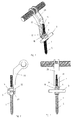
- FIG. 8 shows isolated the bone screw 1, which has a for insertion into the bone having first thread cuts 5. Adjacent to the first thread section 5 is a shaft collar 6 and at the opposite end of the first threaded portion 5 of the screw shaft 2 of the bone screw 1, a second threaded portion 7 is formed. In the screw shaft runs for cannulation a channel 8 ( Fig. 5 )
- the connector 4 can then be placed on the shaft collar 6 of the bone screw 1, which connector has a connector body 9 with a passage opening 10 and a rod receptacle 11 open on one side, into which the rod 3 can be clipped using a spring effect.
- a corresponding connector is isolated in the FIG. 9 shown, which shows that the connector body 9 has a body base 12 and two spaced at a distance body limbs 13 which carry at their free end respectively body webs 14 which adapted to the peripheral shape of the rod 3 locking seat 15, each utilizing at least one form web bar 16 connected to the body web 14.
- FIG. 9 Also shows that the passage opening 10 is formed in the connector body 9 as a slot having inclined to the longitudinal axis of the connector 4 extending side walls, so that there is the possibility limited by the side walls as stops, the connector 4 about its longitudinal axis on the screw shaft. 2 to twist.
- the corresponding adjustment possibility of the connector 4 relative to the bone screw 1 is in the FIGS. 6 and 7 illustrated.
- the washer 18 has a connector 4 adapted and intended for engagement with the fixing nut 17 second side. Under exploitation a predetermined breaking point or formed in the region of the second threaded portion 7 slots 19, the screw shaft 2 can be shortened.
- the connector 4 prior to the positioning of the rod 3 in the rod holder 11 of the connector 4, this is first used to achieve a correct orientation and positioning of the vertebral body in the spine, including the connector 4 as a coupling member for connecting a Repositeurs 20 is formed by an on the connector body 9 in the region of the body base 12 extending in the circumferential direction annular groove 21.
- the repositeur 20 can be pushed with a groove 22 associated therewith, which is used to by applying appropriate leverage over the bone screw 1 to cause the change in position of the vertebral body.
- the orientation of the vertebral body achieved in this way can be fixed with the bone screw 1 by using the optionally suitably bent rod 3, so that then the repository 20 can be pulled off the connector 4 acting as a coupling member.
Description
Die Erfindung betrifft eine Vorrichtung zur Stabilisierung der Wirbelsäule, mit einer einen Schraubenschaft aufweisenden Knochenschraube, die einen zum Einbringen in den Knochen aufweisenden ersten Gewindeabschnitt aufweist, mit einem Stab und mit einem an der Knochenschraube befestigbaren Verbinder zum lösbaren Verbinden des Stabes mit der Knochenschraube, wobei der Verbinder einen Verbinderkörper mit einer Durchgangsöffnung und einer einseitig offenen Stabaufnahme aufweist, die durch zwei einander gegenüberliegende, zur Bildung eines Rastsitzes jeweils mindestens eine Stegleiste aufweisende Körperstege gebildet ist.The invention relates to a device for stabilizing the spine, comprising a screw shaft having a bone screw having a first threaded portion for insertion into the bone, with a rod and with a fastened to the bone screw connector for releasably connecting the rod to the bone screw the connector has a connector body with a passage opening and a rod receptacle open on one side, which is formed by two opposing body webs each having at least one web bar to form a snap fit.
Bei traumatischen oder degenerativen Erkrankungen der Wirbelsäule ergibt sich oftmals das Erfordernis, zur Wiederherstellung und Gewährleistung der tragenden Funktion der Wirbelsäule diese mittels einer Instrumentierung zu stabilisieren. Als Beispiel für eine derartige Instrumentierung kann das in der
Eine Vorrichtung der eingangs genannten Art ist aus der
Der Erfindung liegt die Aufgabe zugrunde, eine Vorrichtung zur Stabilisierung der Wirbelsäule der eingangs genannten Art so auszubilden, dass die Handhabung während der Operation vereinfacht ist.The invention has the object of providing a device for stabilizing the spine of the type mentioned in such a way that the handling is simplified during the operation.
Diese Aufgabe wird nach der Erfindung bei einer Vorrichtung der eingangs genannten Art dadurch gelöst, dass die Stegleisten (16) die seitliche Öffnungsweite der Stabaufnahme (11) begrenzen derart, dass beim Einsclipsen des Stabes (3) in die Stabaufnahme (11) unter Ausnutzung einer Federwirkung zunächst eine Aufweitung der Stabaufnahme (11) mittels einer Auslenkung der Körperstege (14) erfolgt, und dass infolge der gewünschten Federwirkung die Körperstege (14) den Stab (3) nach der Einführung fest umschließen und einen an die Umfanggestalt des Stabes (3) angepassten Rastsitz bilden.This object is achieved according to the invention in a device of the type mentioned in that the web strips (16) limit the lateral opening width of the rod holder (11) such that when Einsclipsen the rod (3) in the rod holder (11) taking advantage of a Spring effect, first a widening of the rod receptacle (11) by means of a deflection of the body webs (14), and that due to the desired spring action, the body webs (14) tightly enclose the rod (3) after insertion and one to the peripheral shape of the rod (3) form adapted snap fit.
Mit einer derartigen Gestaltung des Verbinders eines Stab-Schraubensystems ist der große Vorteil verbunden, dass nicht der Stab einzeln mit einer Bewegung in Richtung seiner Längsachse in die einzelnen Ringösen der verwendeten Verbinder eingeführt werden muss, sondern in einer seitlichen, in radialer Richtung zu der Stablängsachse erfolgenden Bewegung die Positionierung des Stabes an der Knochenschraube mittels des Verbinders erfolgen kann.With such a design of the connector of a rod-screw system has the great advantage that not the rod individually with a movement in the direction of its longitudinal axis in the individual Ring eyelets of the connector used must be introduced, but in a lateral, in the radial direction of the rod longitudinal axis movement taking place, the positioning of the rod to the bone screw can be done by means of the connector.
Um die Einführung des Stabes in die Rastaufnahme zu vereinfachen, ist im Rahmen der Erfindung weiterhin vorgesehen, dass die Körperstege an zwei mit gegenseitigem Abstand an einer Körperbasis angeschlossenen Körperschenkeln ausgebildet sind. Durch diese Gestaltung wird der Vorteil erreicht, dass für den Verbinderkörper eine große Materialstärke mit entsprechend hoher Belastbarkeit bereitgestellt werden kann, ohne die Auslenkbarkeit der Körperstege zu beeinträchtigen, da die Auslenkbarkeit der Körperstege und der Körperschenkel kumulativ ausgenutzt werden kann.In order to simplify the introduction of the rod into the locking receptacle, it is further provided in the context of the invention that the body webs are formed on two body limbs connected at a mutual distance to a body base. By this design, the advantage is achieved that a large material thickness can be provided with a correspondingly high load capacity for the connector body, without affecting the deflectability of the body webs, since the deflectability of the body webs and the body limb can be utilized cumulatively.
Wenn die Durchgangsöffnung als Langloch im Verbinderkörper ausgebildet ist, besteht die Möglichkeit einer verbesserten Justierungsmöglichkeit des Verbinders und damit des Stabes relativ zu der Knochenschraube. Dabei ist dann bevorzugt, dass das Langloch in dem Körperschenkel ausgebildet ist und geneigt zur Längsachse des Verbinders verlaufende Seitenwände aufweist, die dann als Anschläge für die Knochenschraube bei der Begrenzung des Verstellwinkels dienen.If the passage opening is formed as a slot in the connector body, there is the possibility of an improved adjustment possibility of the connector and thus of the rod relative to the bone screw. It is then preferred that the slot is formed in the body limb and inclined to the longitudinal axis of the connector extending side walls, which then serve as stops for the bone screw in the limitation of the adjustment.
Ganz besonders bevorzugt im Rahmen der Erfindung ist es, wenn der Verbinder als Koppelglied zum Anschließen eines Repositeurs ausgebildet ist. Im Rahmen einer Wirbelsäulenoperation ergibt sich nämlich oftmals das Erfordernis, dass nicht nur die Wirbelkörper als Teil der Wirbelsäule einer Stabilisierung bedürfen, sondern auch eine Ausrichtung der Wirbelkörper relativ zueinander erfolgen muss, um die gewünschte natürliche anatomische Krümmung der Wirbelsäule nachzubilden oder eine seitliche Verkrümmung zu korrigieren. Den Verbinder als Koppelglied zum Anschließen eines Repositeurs auszubilden bieten den Vorteil, dass die bereits in den Wirbelkörpern platzierten Knochenschrauben genutzt werden können, um unter Vermittlung des Verbinders durch den Repositeur die Ausrichtung der Wirbelkörper zu bewirken, wobei infolge des Stab-Schraubensystems diese so erzielte Ausrichtung dauerhaft fixiert werden kann, so dass ein sehr einfaches System mit wenigen Bauteilen zur Verfügung gestellt ist mit dem mehrfachen Nutzen einer Verwendbarkeit des Verbinders während der Operation als Koppelglied zum Repositeur und als Teil des Stab-Schraubensystems in der Vorrichtung zur Stabilisierung.It is very particularly preferred within the scope of the invention if the connector is designed as a coupling member for connecting a repositor. In the context of a spinal surgery often results in the requirement that not only the vertebral bodies as part of the spine require stabilization, but also an alignment of the vertebral bodies must be relative to each other to simulate the desired natural anatomical curvature of the spine or a lateral curvature to correct. Forming the connector as a coupling member for connecting a Repositeurs offer the advantage that the bone screws already placed in the vertebral bodies can be used to effect the alignment of the vertebral bodies through the intermediary of the connector by the repositor, which due to the rod-screw system, this alignment thus achieved can be permanently fixed so that a very simple system with few components is provided with the multiple benefits of usability of the connector during operation as a coupling member to the repository and as part of the rod screw system in the stabilizer.
Unter Berücksichtigung der Verdrehbarkeit des Verbinders um seine Längsachse durch das im Verbinderkörper ausgebildeten Langloches ist es zweckmäßig, wenn die Strukturen zum Anschließen des Repositeurs die entsprechende Drehbarkeit des Verbinderkörpers nicht beeinträchtigen. Dies wird erzielt, indem der Verbinder am Verbinderkörper eine in Umfangsrichtung verlaufende Ringnut zum Zusammenwirken mit dem Repositeur aufweist.Taking into account the rotatability of the connector about its longitudinal axis through the elongated hole formed in the connector body, it is expedient if the structures for connecting the repository do not impair the corresponding rotatability of the connector body. This is accomplished by having the connector on the connector body have a circumferential annular groove for cooperating with the repository.
Vorteilhaft ist es weiterhin, wenn die Knochenschraube benachbart zum ersten Gewindeabschnitt einen Schaftbund aufweist, da dieser Schaftbund genutzt werden kann, um dem Verbinder eine bestimmte Lage hinsichtlich der axialen Erstreckung der Knochenschraube zuzuweisen, es also nicht erforderlich ist, dass der Verbinder sich selber unmittelbar am Wirbelkörper abstützt.It is furthermore advantageous if the bone screw has a shaft collar adjacent to the first threaded section, since this shaft collar can be used to assign the connector a specific position with respect to the axial extension of the bone screw, ie it is not necessary for the connector to contact itself directly on the bone screw Vertebral body supports.
Im Rahmen der Erfindung ist es weiterhin vorgesehen, dass am Schraubenschaft ein zweiter Gewindeabschnitt ausgebildet ist, und dass ein Fixiermittel zum Zusammenwirken mit dem zweiten Gewindeabschnitt die Vorrichtung zur Stabilisierung der Wirbelsäule ergänzt, da infolge des Zusammenwirkens der Fixiermutter mit dem zweiten Gewindeabschnitt eine Festlegung der Lage des Verbinders relativ zu der Knochenschraube sowie eine Pressung des Stabes in der Stabaufnahme erfolgen kann. Einer verbesserten Kraftübertragung dient dabei, dass eine Unterlegscheibe mit einer in die Umfangsgestalt des Verbinderkörpers angepassten einen Seite und einer zur Anlage an der Fixiermutter bestimmten anderen Seite vorgesehen ist.In the context of the invention, it is further provided that a second threaded portion is formed on the screw shaft, and that a fixing means for cooperation with the second threaded portion complements the device for stabilizing the spine, as a result of Cooperation of the fixing nut with the second threaded portion can be made a determination of the position of the connector relative to the bone screw and a pressure of the rod in the rod holder. In this case, an improved force transmission serves to provide a washer with a side adapted to the peripheral shape of the connector body and a side intended for engagement with the fixing nut.
Als vorteilhaft hat sich im Rahmen der Erfindung weiterhin erwiesen, wenn der Schraubenschaft im Bereich des zweiten Gewindeabschnitts mindestens einen den Schraubenschaft in Schaftstege teilenden Schlitz aufweist, da so in einfacher Weise die Möglichkeit besteht, den zweiten Gewindeabschnitt der Knochenschraube entsprechend den Erfordernissen zu kürzen, um so weit über die Fixiermutter herausstehende Bereiche der Knochenschraube zu vermeiden. Alternativ oder auch ergänzend besteht die Möglichkeit, dass im Bereich des zweiten Gewindeabschnitts mindestens eine Sollbruchstelle ausgebildet ist.It has also proved to be advantageous in the context of the invention if the screw shaft has at least one slot dividing the screw shank into shank webs in the region of the second threaded section, since in a simple manner it is possible to shorten the second threaded section of the bone screw in accordance with the requirements To avoid protruding areas of the bone screw so far beyond the fixation nut. Alternatively or additionally, there is the possibility that at least one predetermined breaking point is formed in the region of the second threaded section.
Im Rahmen der Erfindung ist es wünschenswert, wenn auch unabhängig von einer durch die Fixiermutter auf den Verbinderkörper ausgeübten Kraft bereits eine vorläufige Sicherung des Stabes in der Stabaufnahme gegeben ist, so dass zweckmäßigerweise die Oberfläche der Stabaufnahme und/oder des Stabes die Haltewirkung erhöhende Strukturen und/oder Beschichtungen aufweist. Entsprechenden Strukturen können dabei beispielsweise gebildet sein durch Längs-, Quer- oder Kreuzriefen, die durch eine erhöhte Flächenpressung bzw. entsprechende Kanten oder Noppen ein Eingreifen der einander anliegenden Oberflächen oder zumindest einen Formschluß bewirken.In the context of the invention, it is desirable, although independent of a force exerted by the fixing nut on the connector body force is already given a provisional securing the rod in the rod holder, so that expediently the surface of the rod holder and / or the rod holding structures enhancing structure and / or has coatings. Corresponding structures can be formed, for example, by longitudinal, transverse or Kreuzriefen, which cause by an increased surface pressure or corresponding edges or knobs, an engagement of the adjacent surfaces or at least a positive engagement.
Die Erfindung betrifft weiterhin eine Kombination einer Vorrichtung zur Stabilisierung der Wirbelsäule nach einem der Ansprüche 1 bis 13, bestehend aus einer Knochenschraube, einem Stab und einem Verbinder mit einem Repositeur, wobei der Verbinder als Koppelglied zum Anschließen des Repositeurs ausgebildet ist, indem der Verbinder am Verbinderkörper eine in Umfangsrichtung verlaufende Ringnut zum Zusammenwirken mit einer einenends offenen Nut des Repositeurs aufweist,The invention further relates to a combination of a spinal stabilization device according to any one of
Im folgenden wird die Erfindung an einem in der Zeichnung dargestellten Ausführungsbeispiel näher erläutert; es zeigen:
- Fig. 1
- eine perspektivische Darstellung der erfindungsgemäßen Vorrichtung,
- Fig. 2
- eine Seitenansicht der Vorrichtung aus
Figur 1 - Fig. 3
- eine Vorderansicht der Vorrichtung aus
Figur 1 - Fig. 4
- eine Seitenansicht des Stab-Schraubensystems nach Entfernung Repositeurs,
- Fig. 5
- den Schnitt V - V aus
Figur 4 - Fig. 6
- eine Vorderansicht des Stab-Schrauben-Systems aus
Figur 4 - Fig. 7
- eine der
Figur 6 - Fig. 8
- eine perspektivische Darstellung der isolierten Knochenschraube,
- Fig. 9
- eine perspektivische Darstellung des isolierten Verbinders,
- Fig. 10
- eine perspektivische Darstellung der isolierten Unterlegscheibe, und
- Fig. 11
- eine perspektivische Darstellung der isolierten Fixiermutter.
- Fig. 1
- a perspective view of the device according to the invention,
- Fig. 2
- a side view of the device
FIG. 1 . - Fig. 3
- a front view of the device
FIG. 1 . - Fig. 4
- a side view of the rod screw system after removal repositor,
- Fig. 5
- the cut V - V off
FIG. 4 . - Fig. 6
- a front view of the rod-screw system
FIG. 4 with respect to the screw longitudinal axis twisted connector, - Fig. 7
- one of the
FIG. 6 corresponding representation with respect to the screw longitudinal axis in the other direction twisted connector, - Fig. 8
- a perspective view of the isolated bone screw,
- Fig. 9
- a perspective view of the insulated connector,
- Fig. 10
- a perspective view of the insulated washer, and
- Fig. 11
- a perspective view of the isolated fixing nut.
In der Zeichnung ist eine Vorrichtung zur Stabilisierung der Wirbelsäule gezeigt, die ein Stab-Schrauben-System umfasst gebildet aus den Einzelteilen einer einen Schraubenschaft 2 aufweisenden Knochenschraube 1, einem Stab 3 und einem Verbinder 4.In the drawing, a spinal stabilization device is shown, which comprises a rod-screw system formed from the individual parts of a
Im Rahmen einer Operation zur Stabilisierung der Wirbelsäule ist es vorgesehen, eine Mehrzahl derartiger Knochenschrauben 1 in den Wirbelkörpern der Wirbelsäule mit dem ersten Gewindeabschnitt 5 einzubringen. Auf dem Schaftbund 6 der Knochenschraube 1 kann sodann der Verbinder 4 platziert werden, der einen Verbinderkörper 9 mit einer Durchgangsöffnung 10 und einer einseitig offenen Stabaufnahme 11 aufweist, in die unter Ausnutzung einer Federwirkung der Stab 3 eingeclipst werden kann. Ein entsprechender Verbinder ist isoliert in der
Die
Durch die erfindungsgemäße Vorrichtung ergibt sich allerdings auch die Möglichkeit, dass vor der Positionierung des Stabes 3 in der Stabaufnahme 11 des Verbinders 4 dieser zunächst ausgenutzt wird, um eine korrekte Orientierung und Positionierung des Wirbelkörpers in der Wirbelsäule zu erzielen, wozu der Verbinder 4 als Koppelglied zum Anschließen eines Repositeurs 20 ausgebildet ist durch eine am Verbinderkörper 9 im Bereich der Körperbasis 12 in Umfangsrichtung verlaufende Ringnut 21. In diese Ringnut 21 kann der Repositeur 20 mit einer diesem zugeordneten Nut 22 aufgeschoben werden, der genutzt wird, um durch Anwendung entsprechender Hebelkräfte über die Knochenschraube 1 die Lageänderung des Wirbelkörpers zu bewirken. Nach der erfolgten Reponierung kann die so erzielte Ausrichtung des Wirbelkörpers mit der Knochenschraube 1 durch Anwendung des gegebenenfalls geeignet gebogenen Stabes 3 fixiert werden, so dass dann der Repositeur 20 von dem als Koppelglied wirkenden Verbinder 4 abgezogen werden kann.By the device according to the invention, however, there is also the possibility that prior to the positioning of the
- 11
- Knochenschraubebone screw
- 22
- Schraubenschaftscrew shaft
- 33
- StabRod
- 44
- VerbinderInterconnects
- 55
- erster Gewindeabschnittfirst threaded section
- 66
- Schaftbundshaft collar
- 77
- zweiter Gewindeabschnittsecond threaded section
- 88th
- Kanalchannel
- 99
- Verbinderkörperconnector body
- 1010
- DurchgangsöffnungThrough opening
- 1111
- Stabaufnahmerod reception
- 1212
- Körperbasisbody base
- 1313
- Körperschenkelelement limbs
- 1414
- Körperstegebody webs
- 1515
- RastsitzRest seat
- 1616
- Stegleisteweb strip
- 1717
- Fixiermutterfixing nut
- 1818
- Unterlegscheibewasher
- 1919
- Schlitzslot
- 2020
- RepositeurRepositeur
- 2121
- Ringnutring groove
- 2222
- Nutgroove
Claims (14)
- A device for stabilising the spinal column comprising a bone screw (1) which has a screw shank (2) and which has a first thread portion (5) intended for insertion into the bone, a rod (3) and a connector (4) which can be fixed to the bone screw (1) for releasably connecting the rod (3) to the bone screw (1), the connector (4) having a connector body (9) with a through opening (10) and a rod receiving means (11) which is open at one side and which is formed by two mutually opposite body legs (14) each having at least one respective leg bar (16) for forming a latching seat (15), characterised in that the leg bars (16) delimit the lateral opening width of the rod receiving means (11) in such a way that when the rod (3) is clipped into the rod receiving means (11), enlargement of the rod receiving means (11) occurs by means of a deflection of the body legs (14) by utilising a spring action and that as a result of the desired spring action the body legs (14) fixedly embrace the rod (3) after introduction thereof and form a latching seat adapted to the peripheral configuration of the rod (3).
- A device according to claim 1 characterised in that the body legs (14) are provided on two body limbs (13) connected at a mutual spacing to a body base (12).
- A device according to claim 1 or claim 2 characterised in that the through opening (10) is in the form of a slot in the connector body (9).
- A device according to claim 3 when appended to claim 2 characterised in that the slot is provided in the body limbs (13) and has side walls extending inclinedly relative to the longitudinal axis of the connector (4).
- A device according to one of claims 1 to 4 characterised in that the connector (4) is in the form of a coupling member for connecting a repositor (20).
- A device according to claim 5 characterised in that the connector (4) on the connector body (9) has an annular groove (21) extending in the peripheral direction for co-operation with the repositor (20).
- A device according to one of claims 1 to 6 characterised in that the bone screw (1) has a shank collar (6) adjacent to the first thread portion (5).
- A device according to one of claims 1 to 7 characterised in that a second thread portion (7) is provided on the screw shank (2).
- A device according to claim 8 characterised in that there is provided a fixing nut (17) for co-operating with the second thread portion (7).
- A device according to claim 9 characterised in that there is provided a washer (18) having a one side adapted to the peripheral configuration of the connector body (9) and another side intended for bearing against the fixing nut (17).
- A device according to one of claims 8 to 10 characterised in that in the region of the second thread portion (7) the screw shank (2) has at least one slot (19) dividing the screw shank (2) into shank legs.
- A device according to one of claims 8 to 11 characterised in that at least one desired-fracture location is provided in the region of the second thread portion (7).
- A device according to one of claims 1 to 12 characterised in that the surface of the rod receiving mans (11) and/or of the rod (3) has coatings and/or structures enhancing the holding effect.
- A combination of a device for stabilising the spinal column according to one of claims 1 to 13 comprising a bone screw (1), a rod (3) and a connector (4) having a repositor (20), characterised in that the connector (4) is in the form of a coupling member for connection of the repositor (20) and on the connector body (9) has an annular groove (21) extending in the peripheral direction for co-operation with a groove (22) of the repositor (20), the groove (22) being open at one end.
Applications Claiming Priority (2)
| Application Number | Priority Date | Filing Date | Title |
|---|---|---|---|
| PCT/DE2009/075005 WO2010094250A1 (en) | 2009-02-19 | 2009-02-19 | Device for stabilizing the spinal column |
| US12/388,649 US8597332B2 (en) | 2009-02-19 | 2009-02-19 | Apparatus for spinal-column stabilization |
Publications (2)
| Publication Number | Publication Date |
|---|---|
| EP2249725A1 EP2249725A1 (en) | 2010-11-17 |
| EP2249725B1 true EP2249725B1 (en) | 2015-06-10 |
Family
ID=43038116
Family Applications (1)
| Application Number | Title | Priority Date | Filing Date |
|---|---|---|---|
| EP09736551.4A Not-in-force EP2249725B1 (en) | 2009-02-19 | 2009-02-19 | Device for stabilizing the spinal column |
Country Status (3)
| Country | Link |
|---|---|
| US (1) | US8597332B2 (en) |
| EP (1) | EP2249725B1 (en) |
| WO (1) | WO2010094250A1 (en) |
Families Citing this family (15)
| Publication number | Priority date | Publication date | Assignee | Title |
|---|---|---|---|---|
| GB0605960D0 (en) * | 2006-03-24 | 2006-05-03 | Galley Geoffrey H | Expandable spinal prosthesis |
| US9060813B1 (en) | 2008-02-29 | 2015-06-23 | Nuvasive, Inc. | Surgical fixation system and related methods |
| US9504494B2 (en) | 2008-04-28 | 2016-11-29 | DePuy Synthes Products, Inc. | Implants for securing spinal fixation elements |
| US9198696B1 (en) | 2010-05-27 | 2015-12-01 | Nuvasive, Inc. | Cross-connector and related methods |
| US9247964B1 (en) | 2011-03-01 | 2016-02-02 | Nuasive, Inc. | Spinal Cross-connector |
| US9387013B1 (en) | 2011-03-01 | 2016-07-12 | Nuvasive, Inc. | Posterior cervical fixation system |
| US9339305B2 (en) | 2011-09-19 | 2016-05-17 | DePuy Synthes Products, Inc. | Snap fit rod and fastener system |
| US8940020B2 (en) | 2012-04-06 | 2015-01-27 | DePuy Synthes Products, LLC | Rod connector |
| US10034690B2 (en) * | 2014-12-09 | 2018-07-31 | John A. Heflin | Spine alignment system |
| ITUB20155792A1 (en) * | 2015-11-20 | 2017-05-20 | Medacta Int Sa | OCCIPITAL PLATE FOR STATIONARY-CERVICAL FIXING AND SYSTEM FOR STATIONARY-CERVICAL FIXING |
| US10682160B2 (en) * | 2015-12-03 | 2020-06-16 | Globus Medical, Inc. | External fixator assembly |
| FR3062056B1 (en) * | 2017-01-25 | 2023-08-25 | Lape Medical | SPINAL OSTEOSYNTHESIS SYSTEM |
| FR3080018A1 (en) * | 2018-04-12 | 2019-10-18 | Richard Assaker | TRIANGULATION ASSEMBLY FOR VERTEBRATES RECOVERY, AND SPINAL OSTEOSYNTHESIS SYSTEM COMPRISING SUCH ASSEMBLIES |
| US11331125B1 (en) | 2021-10-07 | 2022-05-17 | Ortho Inventions, Llc | Low profile rod-to-rod coupler |
| FR3136149A1 (en) * | 2022-06-01 | 2023-12-08 | Paul Fayada | Spinal stabilization device |
Family Cites Families (33)
| Publication number | Priority date | Publication date | Assignee | Title |
|---|---|---|---|---|
| US4653481A (en) * | 1985-07-24 | 1987-03-31 | Howland Robert S | Advanced spine fixation system and method |
| US5024213A (en) * | 1989-02-08 | 1991-06-18 | Acromed Corporation | Connector for a corrective device |
| US5030220A (en) * | 1990-03-29 | 1991-07-09 | Advanced Spine Fixation Systems Incorporated | Spine fixation system |
| US5810817A (en) * | 1992-06-19 | 1998-09-22 | Roussouly; Pierre | Spinal therapy apparatus |
| US5545164A (en) * | 1992-12-28 | 1996-08-13 | Advanced Spine Fixation Systems, Incorporated | Occipital clamp assembly for cervical spine rod fixation |
| FR2718945B1 (en) * | 1994-04-25 | 1996-07-05 | Soprane Sa | Device for retaining a connecting rod of a spine fixator on a pedicle screw. |
| FR2742040B1 (en) * | 1995-12-07 | 1998-01-23 | Groupe Lepine | ASSEMBLY DEVICE FOR EXTENDED PARTS OF OSTEOSYNTHESIS MATERIAL, ESPECIALLY SPINAL |
| US5709685A (en) * | 1996-05-21 | 1998-01-20 | Sdgi Holdings, Inc. | Positionable clip for provisionally capturing a component on a spinal rod |
| WO1998017188A1 (en) * | 1996-10-24 | 1998-04-30 | Spinal Concepts, Inc. | Method and apparatus for spinal fixation |
| US6416515B1 (en) * | 1996-10-24 | 2002-07-09 | Spinal Concepts, Inc. | Spinal fixation system |
| US5810819A (en) * | 1997-05-15 | 1998-09-22 | Spinal Concepts, Inc. | Polyaxial pedicle screw having a compression locking rod gripping mechanism |
| DE69721278T2 (en) * | 1997-12-17 | 2004-02-05 | Robert Lange | Apparatus for stabilizing certain vertebrae of the spine |
| US6123707A (en) * | 1999-01-13 | 2000-09-26 | Spinal Concepts, Inc. | Reduction instrument |
| ES2156527B1 (en) | 1999-01-20 | 2002-01-16 | Alacreu Jose Barbera | VERTEBRAL FIXING SYSTEM DORSO-LUMBAR AND LUMBO-SACRO. |
| US6554831B1 (en) * | 2000-09-01 | 2003-04-29 | Hopital Sainte-Justine | Mobile dynamic system for treating spinal disorder |
| US6746449B2 (en) * | 2001-09-12 | 2004-06-08 | Spinal Concepts, Inc. | Spinal rod translation instrument |
| US6800078B2 (en) * | 2001-11-07 | 2004-10-05 | Lock-N-Stitch, Inc. | Orthopedic stabilization device and method |
| ATE300245T1 (en) * | 2002-02-11 | 2005-08-15 | Synthes Ag | DEVICE FOR CONNECTING A LONGITUDINAL BEAM TO A BONE |
| US7066938B2 (en) * | 2002-09-09 | 2006-06-27 | Depuy Spine, Inc. | Snap-on spinal rod connector |
| JP4047113B2 (en) * | 2002-09-12 | 2008-02-13 | 昭和医科工業株式会社 | Rod connector |
| WO2004082522A2 (en) | 2003-01-31 | 2004-09-30 | Murray Ian P | Multi-axial positioning system for a surgically-implanted spinal support |
| WO2004075778A2 (en) * | 2003-02-25 | 2004-09-10 | Stephen Ritland | Adjustable rod and connector device and method of use |
| FR2856581B1 (en) * | 2003-06-27 | 2005-08-19 | Medicrea | MATERIAL OF VERTEBRAL OSTEOSYNTHESIS |
| FR2856579B1 (en) * | 2003-06-27 | 2006-03-17 | Medicrea | VERTEBRAL OSTEOSYNTHESIS EQUIPMENT AND METHOD FOR MANUFACTURING BONE ANCHORING MEMBER INCLUDING THESE MATERIALS |
| FR2856580B1 (en) * | 2003-06-27 | 2006-03-17 | Medicrea | MATERIAL OF VERTEBRAL OSTEOSYNTHESIS |
| US7090674B2 (en) * | 2003-11-03 | 2006-08-15 | Spinal, Llc | Bone fixation system with low profile fastener |
| GB0406822D0 (en) * | 2004-03-25 | 2004-04-28 | Depuy Int Ltd | Surgical fastening |
| US7744635B2 (en) * | 2004-06-09 | 2010-06-29 | Spinal Generations, Llc | Spinal fixation system |
| US7404818B2 (en) * | 2004-11-30 | 2008-07-29 | Warsaw Orthopedic, Inc. | Side-loading adjustable bone anchor |
| US7578833B2 (en) * | 2004-12-13 | 2009-08-25 | Dr. Robert S. Bray, Jr. | Bone fastener assembly for bone retention apparatus |
| US7585299B2 (en) * | 2006-02-17 | 2009-09-08 | Warsaw Orthopedic, Inc. | Dorsal adjusting spinal connector assembly |
| US8057518B2 (en) * | 2007-08-31 | 2011-11-15 | Depuy Spine, Inc. | Spanning connector for connecting a spinal fixation element and an offset bone anchor |
| US8092503B2 (en) * | 2008-05-15 | 2012-01-10 | Innovasis, Inc. | Polyaxial screw system |
-
2009
- 2009-02-19 WO PCT/DE2009/075005 patent/WO2010094250A1/en active Application Filing
- 2009-02-19 EP EP09736551.4A patent/EP2249725B1/en not_active Not-in-force
- 2009-02-19 US US12/388,649 patent/US8597332B2/en not_active Expired - Fee Related
Also Published As
| Publication number | Publication date |
|---|---|
| US20100211100A1 (en) | 2010-08-19 |
| EP2249725A1 (en) | 2010-11-17 |
| WO2010094250A1 (en) | 2010-08-26 |
| US8597332B2 (en) | 2013-12-03 |
Similar Documents
| Publication | Publication Date | Title |
|---|---|---|
| EP2249725B1 (en) | Device for stabilizing the spinal column | |
| DE69925374T2 (en) | SPINAL OSTEOSYNTHESIS SYSTEM WITH IMPROVED STABILITY | |
| EP1372502B1 (en) | Anchor element | |
| DE60032225T2 (en) | APPARATUS FOR STABILIZING THE SPINE | |
| EP1764048B1 (en) | Ventral plate | |
| DE102006021025B3 (en) | Surgical fixation device for two bone parts | |
| DE69929406T2 (en) | Device for fixing the spine | |
| DE69831188T2 (en) | pedicle screw | |
| EP1474051B1 (en) | Device for linking a longitudinal support with a bone | |
| EP1287787B1 (en) | Implant for the fixation of bone fractures | |
| EP2452642B1 (en) | Pedicle screw | |
| EP2074957B1 (en) | Pedicle screw with a locking device for attaching a rod to stabilise the spine | |
| DE10005386A1 (en) | Pedicle screw for spinal implants takes round bar whose longitudinally rotating shoe notchably accepts notch-legged clip for bar. | |
| EP0659062A1 (en) | Posterior vertebral column implant | |
| EP1663031A1 (en) | Longitudinal support | |
| DE10005385A1 (en) | Pedicle screw | |
| WO2014037220A1 (en) | Pelvic ring implant | |
| DE3021238A1 (en) | ARRANGEMENT WITH HOOK-SHAPED ELEMENTS | |
| EP1667591A1 (en) | Device for elastically stabilising vertebral bodies | |
| EP1261288A1 (en) | Connector element for bone rods or spinal rods | |
| DE202009018581U1 (en) | Adjustable bar arrangement | |
| EP1815812A1 (en) | Spinal implant | |
| DE19628147A1 (en) | Surgical bone fixing device | |
| EP0461374A1 (en) | Device for bracing human vertebral column vertebras | |
| DE102016108504A1 (en) | Medical instrument for temporary fixation of a polyaxial pedicle screw |
Legal Events
| Date | Code | Title | Description |
|---|---|---|---|
| PUAI | Public reference made under article 153(3) epc to a published international application that has entered the european phase |
Free format text: ORIGINAL CODE: 0009012 |
|
| AK | Designated contracting states |
Kind code of ref document: A1 Designated state(s): AT BE BG CH CY CZ DE DK EE ES FI FR GB GR HR HU IE IS IT LI LT LU LV MC MK MT NL NO PL PT RO SE SI SK TR |
|
| AX | Request for extension of the european patent |
Extension state: AL BA RS |
|
| 17P | Request for examination filed |
Effective date: 20101125 |
|
| RIN1 | Information on inventor provided before grant (corrected) |
Inventor name: WERNER, CLAUDIA |
|
| DAX | Request for extension of the european patent (deleted) | ||
| GRAP | Despatch of communication of intention to grant a patent |
Free format text: ORIGINAL CODE: EPIDOSNIGR1 |
|
| INTG | Intention to grant announced |
Effective date: 20150204 |
|
| GRAS | Grant fee paid |
Free format text: ORIGINAL CODE: EPIDOSNIGR3 |
|
| GRAA | (expected) grant |
Free format text: ORIGINAL CODE: 0009210 |
|
| AK | Designated contracting states |
Kind code of ref document: B1 Designated state(s): AT BE BG CH CY CZ DE DK EE ES FI FR GB GR HR HU IE IS IT LI LT LU LV MC MK MT NL NO PL PT RO SE SI SK TR |
|
| REG | Reference to a national code |
Ref country code: GB Ref legal event code: FG4D Free format text: NOT ENGLISH |
|
| REG | Reference to a national code |
Ref country code: CH Ref legal event code: EP |
|
| REG | Reference to a national code |
Ref country code: AT Ref legal event code: REF Ref document number: 730579 Country of ref document: AT Kind code of ref document: T Effective date: 20150715 |
|
| REG | Reference to a national code |
Ref country code: DE Ref legal event code: R096 Ref document number: 502009011131 Country of ref document: DE |
|
| REG | Reference to a national code |
Ref country code: IE Ref legal event code: FG4D Free format text: LANGUAGE OF EP DOCUMENT: GERMAN |
|
| PG25 | Lapsed in a contracting state [announced via postgrant information from national office to epo] |
Ref country code: NO Free format text: LAPSE BECAUSE OF FAILURE TO SUBMIT A TRANSLATION OF THE DESCRIPTION OR TO PAY THE FEE WITHIN THE PRESCRIBED TIME-LIMIT Effective date: 20150910 Ref country code: ES Free format text: LAPSE BECAUSE OF FAILURE TO SUBMIT A TRANSLATION OF THE DESCRIPTION OR TO PAY THE FEE WITHIN THE PRESCRIBED TIME-LIMIT Effective date: 20150610 Ref country code: FI Free format text: LAPSE BECAUSE OF FAILURE TO SUBMIT A TRANSLATION OF THE DESCRIPTION OR TO PAY THE FEE WITHIN THE PRESCRIBED TIME-LIMIT Effective date: 20150610 Ref country code: LT Free format text: LAPSE BECAUSE OF FAILURE TO SUBMIT A TRANSLATION OF THE DESCRIPTION OR TO PAY THE FEE WITHIN THE PRESCRIBED TIME-LIMIT Effective date: 20150610 |
|
| REG | Reference to a national code |
Ref country code: NL Ref legal event code: MP Effective date: 20150610 |
|
| PG25 | Lapsed in a contracting state [announced via postgrant information from national office to epo] |
Ref country code: LV Free format text: LAPSE BECAUSE OF FAILURE TO SUBMIT A TRANSLATION OF THE DESCRIPTION OR TO PAY THE FEE WITHIN THE PRESCRIBED TIME-LIMIT Effective date: 20150610 Ref country code: BG Free format text: LAPSE BECAUSE OF FAILURE TO SUBMIT A TRANSLATION OF THE DESCRIPTION OR TO PAY THE FEE WITHIN THE PRESCRIBED TIME-LIMIT Effective date: 20150910 Ref country code: GR Free format text: LAPSE BECAUSE OF FAILURE TO SUBMIT A TRANSLATION OF THE DESCRIPTION OR TO PAY THE FEE WITHIN THE PRESCRIBED TIME-LIMIT Effective date: 20150911 |
|
| PG25 | Lapsed in a contracting state [announced via postgrant information from national office to epo] |
Ref country code: EE Free format text: LAPSE BECAUSE OF FAILURE TO SUBMIT A TRANSLATION OF THE DESCRIPTION OR TO PAY THE FEE WITHIN THE PRESCRIBED TIME-LIMIT Effective date: 20150610 |
|
| PG25 | Lapsed in a contracting state [announced via postgrant information from national office to epo] |
Ref country code: PT Free format text: LAPSE BECAUSE OF FAILURE TO SUBMIT A TRANSLATION OF THE DESCRIPTION OR TO PAY THE FEE WITHIN THE PRESCRIBED TIME-LIMIT Effective date: 20151012 Ref country code: CZ Free format text: LAPSE BECAUSE OF FAILURE TO SUBMIT A TRANSLATION OF THE DESCRIPTION OR TO PAY THE FEE WITHIN THE PRESCRIBED TIME-LIMIT Effective date: 20150610 Ref country code: SK Free format text: LAPSE BECAUSE OF FAILURE TO SUBMIT A TRANSLATION OF THE DESCRIPTION OR TO PAY THE FEE WITHIN THE PRESCRIBED TIME-LIMIT Effective date: 20150610 Ref country code: RO Free format text: LAPSE BECAUSE OF NON-PAYMENT OF DUE FEES Effective date: 20150610 Ref country code: IS Free format text: LAPSE BECAUSE OF FAILURE TO SUBMIT A TRANSLATION OF THE DESCRIPTION OR TO PAY THE FEE WITHIN THE PRESCRIBED TIME-LIMIT Effective date: 20151010 Ref country code: PL Free format text: LAPSE BECAUSE OF FAILURE TO SUBMIT A TRANSLATION OF THE DESCRIPTION OR TO PAY THE FEE WITHIN THE PRESCRIBED TIME-LIMIT Effective date: 20150610 |
|
| REG | Reference to a national code |
Ref country code: DE Ref legal event code: R097 Ref document number: 502009011131 Country of ref document: DE |
|
| PLBE | No opposition filed within time limit |
Free format text: ORIGINAL CODE: 0009261 |
|
| STAA | Information on the status of an ep patent application or granted ep patent |
Free format text: STATUS: NO OPPOSITION FILED WITHIN TIME LIMIT |
|
| PG25 | Lapsed in a contracting state [announced via postgrant information from national office to epo] |
Ref country code: IT Free format text: LAPSE BECAUSE OF FAILURE TO SUBMIT A TRANSLATION OF THE DESCRIPTION OR TO PAY THE FEE WITHIN THE PRESCRIBED TIME-LIMIT Effective date: 20150610 Ref country code: DK Free format text: LAPSE BECAUSE OF FAILURE TO SUBMIT A TRANSLATION OF THE DESCRIPTION OR TO PAY THE FEE WITHIN THE PRESCRIBED TIME-LIMIT Effective date: 20150610 |
|
| 26N | No opposition filed |
Effective date: 20160311 |
|
| PG25 | Lapsed in a contracting state [announced via postgrant information from national office to epo] |
Ref country code: SI Free format text: LAPSE BECAUSE OF FAILURE TO SUBMIT A TRANSLATION OF THE DESCRIPTION OR TO PAY THE FEE WITHIN THE PRESCRIBED TIME-LIMIT Effective date: 20150610 Ref country code: BE Free format text: LAPSE BECAUSE OF NON-PAYMENT OF DUE FEES Effective date: 20160229 |
|
| PG25 | Lapsed in a contracting state [announced via postgrant information from national office to epo] |
Ref country code: MC Free format text: LAPSE BECAUSE OF FAILURE TO SUBMIT A TRANSLATION OF THE DESCRIPTION OR TO PAY THE FEE WITHIN THE PRESCRIBED TIME-LIMIT Effective date: 20150610 Ref country code: LU Free format text: LAPSE BECAUSE OF FAILURE TO SUBMIT A TRANSLATION OF THE DESCRIPTION OR TO PAY THE FEE WITHIN THE PRESCRIBED TIME-LIMIT Effective date: 20160219 |
|
| REG | Reference to a national code |
Ref country code: CH Ref legal event code: PL |
|
| GBPC | Gb: european patent ceased through non-payment of renewal fee |
Effective date: 20160219 |
|
| PG25 | Lapsed in a contracting state [announced via postgrant information from national office to epo] |
Ref country code: LI Free format text: LAPSE BECAUSE OF NON-PAYMENT OF DUE FEES Effective date: 20160229 Ref country code: CH Free format text: LAPSE BECAUSE OF NON-PAYMENT OF DUE FEES Effective date: 20160229 |
|
| REG | Reference to a national code |
Ref country code: FR Ref legal event code: ST Effective date: 20161028 |
|
| REG | Reference to a national code |
Ref country code: IE Ref legal event code: MM4A |
|
| PG25 | Lapsed in a contracting state [announced via postgrant information from national office to epo] |
Ref country code: FR Free format text: LAPSE BECAUSE OF NON-PAYMENT OF DUE FEES Effective date: 20160229 Ref country code: GB Free format text: LAPSE BECAUSE OF NON-PAYMENT OF DUE FEES Effective date: 20160219 Ref country code: IE Free format text: LAPSE BECAUSE OF NON-PAYMENT OF DUE FEES Effective date: 20160219 |
|
| REG | Reference to a national code |
Ref country code: AT Ref legal event code: MM01 Ref document number: 730579 Country of ref document: AT Kind code of ref document: T Effective date: 20160219 |
|
| PG25 | Lapsed in a contracting state [announced via postgrant information from national office to epo] |
Ref country code: AT Free format text: LAPSE BECAUSE OF NON-PAYMENT OF DUE FEES Effective date: 20160219 |
|
| PG25 | Lapsed in a contracting state [announced via postgrant information from national office to epo] |
Ref country code: SE Free format text: LAPSE BECAUSE OF FAILURE TO SUBMIT A TRANSLATION OF THE DESCRIPTION OR TO PAY THE FEE WITHIN THE PRESCRIBED TIME-LIMIT Effective date: 20150610 Ref country code: NL Free format text: LAPSE BECAUSE OF FAILURE TO SUBMIT A TRANSLATION OF THE DESCRIPTION OR TO PAY THE FEE WITHIN THE PRESCRIBED TIME-LIMIT Effective date: 20150610 |
|
| PG25 | Lapsed in a contracting state [announced via postgrant information from national office to epo] |
Ref country code: MT Free format text: LAPSE BECAUSE OF FAILURE TO SUBMIT A TRANSLATION OF THE DESCRIPTION OR TO PAY THE FEE WITHIN THE PRESCRIBED TIME-LIMIT Effective date: 20150610 |
|
| PG25 | Lapsed in a contracting state [announced via postgrant information from national office to epo] |
Ref country code: CY Free format text: LAPSE BECAUSE OF FAILURE TO SUBMIT A TRANSLATION OF THE DESCRIPTION OR TO PAY THE FEE WITHIN THE PRESCRIBED TIME-LIMIT Effective date: 20150610 Ref country code: HU Free format text: LAPSE BECAUSE OF FAILURE TO SUBMIT A TRANSLATION OF THE DESCRIPTION OR TO PAY THE FEE WITHIN THE PRESCRIBED TIME-LIMIT; INVALID AB INITIO Effective date: 20090219 |
|
| PG25 | Lapsed in a contracting state [announced via postgrant information from national office to epo] |
Ref country code: HR Free format text: LAPSE BECAUSE OF FAILURE TO SUBMIT A TRANSLATION OF THE DESCRIPTION OR TO PAY THE FEE WITHIN THE PRESCRIBED TIME-LIMIT Effective date: 20150610 Ref country code: MK Free format text: LAPSE BECAUSE OF FAILURE TO SUBMIT A TRANSLATION OF THE DESCRIPTION OR TO PAY THE FEE WITHIN THE PRESCRIBED TIME-LIMIT Effective date: 20150610 Ref country code: TR Free format text: LAPSE BECAUSE OF FAILURE TO SUBMIT A TRANSLATION OF THE DESCRIPTION OR TO PAY THE FEE WITHIN THE PRESCRIBED TIME-LIMIT Effective date: 20150610 |
|
| PGFP | Annual fee paid to national office [announced via postgrant information from national office to epo] |
Ref country code: DE Payment date: 20181130 Year of fee payment: 11 |
|
| REG | Reference to a national code |
Ref country code: DE Ref legal event code: R119 Ref document number: 502009011131 Country of ref document: DE |
|
| PG25 | Lapsed in a contracting state [announced via postgrant information from national office to epo] |
Ref country code: DE Free format text: LAPSE BECAUSE OF NON-PAYMENT OF DUE FEES Effective date: 20200901 |