EP2249585B1 - Method of generating an optimized venting channel in a hearing instrument - Google Patents
Method of generating an optimized venting channel in a hearing instrument Download PDFInfo
- Publication number
- EP2249585B1 EP2249585B1 EP10161061.6A EP10161061A EP2249585B1 EP 2249585 B1 EP2249585 B1 EP 2249585B1 EP 10161061 A EP10161061 A EP 10161061A EP 2249585 B1 EP2249585 B1 EP 2249585B1
- Authority
- EP
- European Patent Office
- Prior art keywords
- vent
- starter
- housing shell
- faceplate
- shell
- Prior art date
- Legal status (The legal status is an assumption and is not a legal conclusion. Google has not performed a legal analysis and makes no representation as to the accuracy of the status listed.)
- Not-in-force
Links
Images

Classifications
-
- H—ELECTRICITY
- H04—ELECTRIC COMMUNICATION TECHNIQUE
- H04R—LOUDSPEAKERS, MICROPHONES, GRAMOPHONE PICK-UPS OR LIKE ACOUSTIC ELECTROMECHANICAL TRANSDUCERS; DEAF-AID SETS; PUBLIC ADDRESS SYSTEMS
- H04R25/00—Deaf-aid sets, i.e. electro-acoustic or electro-mechanical hearing aids; Electric tinnitus maskers providing an auditory perception
- H04R25/02—Deaf-aid sets, i.e. electro-acoustic or electro-mechanical hearing aids; Electric tinnitus maskers providing an auditory perception adapted to be supported entirely by ear
-
- H—ELECTRICITY
- H04—ELECTRIC COMMUNICATION TECHNIQUE
- H04R—LOUDSPEAKERS, MICROPHONES, GRAMOPHONE PICK-UPS OR LIKE ACOUSTIC ELECTROMECHANICAL TRANSDUCERS; DEAF-AID SETS; PUBLIC ADDRESS SYSTEMS
- H04R25/00—Deaf-aid sets, i.e. electro-acoustic or electro-mechanical hearing aids; Electric tinnitus maskers providing an auditory perception
- H04R25/45—Prevention of acoustic reaction, i.e. acoustic oscillatory feedback
- H04R25/453—Prevention of acoustic reaction, i.e. acoustic oscillatory feedback electronically
-
- H—ELECTRICITY
- H04—ELECTRIC COMMUNICATION TECHNIQUE
- H04R—LOUDSPEAKERS, MICROPHONES, GRAMOPHONE PICK-UPS OR LIKE ACOUSTIC ELECTROMECHANICAL TRANSDUCERS; DEAF-AID SETS; PUBLIC ADDRESS SYSTEMS
- H04R25/00—Deaf-aid sets, i.e. electro-acoustic or electro-mechanical hearing aids; Electric tinnitus maskers providing an auditory perception
- H04R25/65—Housing parts, e.g. shells, tips or moulds, or their manufacture
- H04R25/652—Ear tips; Ear moulds
-
- H—ELECTRICITY
- H04—ELECTRIC COMMUNICATION TECHNIQUE
- H04R—LOUDSPEAKERS, MICROPHONES, GRAMOPHONE PICK-UPS OR LIKE ACOUSTIC ELECTROMECHANICAL TRANSDUCERS; DEAF-AID SETS; PUBLIC ADDRESS SYSTEMS
- H04R25/00—Deaf-aid sets, i.e. electro-acoustic or electro-mechanical hearing aids; Electric tinnitus maskers providing an auditory perception
- H04R25/65—Housing parts, e.g. shells, tips or moulds, or their manufacture
- H04R25/658—Manufacture of housing parts
-
- H—ELECTRICITY
- H04—ELECTRIC COMMUNICATION TECHNIQUE
- H04R—LOUDSPEAKERS, MICROPHONES, GRAMOPHONE PICK-UPS OR LIKE ACOUSTIC ELECTROMECHANICAL TRANSDUCERS; DEAF-AID SETS; PUBLIC ADDRESS SYSTEMS
- H04R2225/00—Details of deaf aids covered by H04R25/00, not provided for in any of its subgroups
- H04R2225/77—Design aspects, e.g. CAD, of hearing aid tips, moulds or housings
Definitions
- a vent (also referenced to herein as a "venting channel”) is an important part of a hearing aid.
- a vent is required to provide air circulation and minimize occlusion. If a vent is not provided, a user will likely have an uneasy feeling caused by an unequal pressure differential present in a space between the user's ear drum and an inner ear canal end of the hearing aid housing compared to the atmospheric pressure external to the hearing aid housing outwardly of the ear. Users have described this uneasy feeling as an unnatural pressure differential. Users have also complained of what has been described as an unnatural hollow sound when the hearing aid is used if no vent is provided. Furthermore, care must be given in choosing the size of the vent since if the vent is too large, undesirable acoustic feedback may occur. When marketing experts in the hearing aid industry are asked which shell they would consider ideal, many of them will indicate a shell as small as possible, but with a vent as big as possible.
- the term "shell” used herein means an outermost wall of the hearing aid housing.
- a "collection vent” is a known prior art vent in hearing aids which starts as a regular round vent at a faceplate outer side of the hearing aid (also called a “starter vent” hereafter) and continues some distance as a round vent and then increases in diameter gradually until some size specified by a designer and which terminates at the canal side of the hearing aid near the ear drum.
- EP 2 048 895 discloses a computerised rule-based binaural modelling system for hearing aid design in which rule-based protocol handling for the shell model is used based on a shell type.
- a computerized method for designing a vent in a hearing aid housing shell based on an image of a patient's ear canal impression, and wherein a program is provided on a computer-readable medium.
- a program is provided on a computer-readable medium.
- an image of a starter housing shell based on the image of the patient's ear canal impression is created which is longer than a final version of the housing shell to be created.
- a starter vent running from an inner canal end near the patient's ear drum to an outer end of the starter housing shell is placed inside the shell.
- Components are then placed substantially as deep as possible inside the starter shell but lying outside of the starter vent. Portions of the starter shell lying beyond where a faceplate is to be mounted are removed and the faceplate is mounted.
- the starter vent is then grown larger so that it fills substantially all space inside the shell without interfering with the components.
- venting channel means a structure inside the shell that permits air flow between the inner ear canal near the ear drum and the outside atmosphere where the user is located.
- a main goal is to provide an automated software design method which provides a vent of a biggest possible size, while having the shell of the hearing aid of a smallest possible size.
- a size of the shell is a more important constraint than a size of the vent.
- a big vent is desired by a patient to improve air circulation in the ear and to minimize the occlusion effect. The occlusion effect is minimized as the vent acoustic mass is decreased.
- vent designed by the present software techniques of the preferred embodiment is hereinafter known as the "vent-as-large-as-possible” and alternately is also referred to as a "size-maximized vent”.
- the receiver 7 and other components 5 are located in the housing shell as shown in Fig. 3 and discussed hereafter.
- the receiver emits sound into the ear of the patient via a receiver tube 7A which runs from a receiver spout 7B of the receiver 7 where sound exits the receiver 7, and runs from there to a receiver hole 6, which is a hole on the shell 8 close to an end 18A of the vent 18 at an innermost end of the housing shell near the ear drum as shown in Fig. 3 .
- a flow chart 9 is provided for the automatic creation of an optimized venting channel (vent) in the hearing instrument by use of software run in a computer.
- first block 10 LOAD WORK ORDER, an order entry is received from a customer. A physical impression of a patient's ear canal is converted to a so-called "point cloud", which is a computer image data file of points on an outside surface of the physical impression. This point cloud data file is then loaded into the computer at block 10.
- a surface file is created by use of a plurality of triangles defined by adjacent point cloud triplets.
- This surface file describes a continuous outer surface of a starter version of the housing shell 8 (see Figs. 2, 3 ). Unnecessary material is removed from the canal area of the end 8A of the shell near the ear canal.
- starter vent 3 which is preferably substantially round in cross-section of relatively small dimensions and runs from the end 8A of the starter shell 8 ( Figs. 2, 3 ) nearest the ear drum to a starter end 8BB lying beyond the outer end 8B of the shell (see Figs. 2, 3 ) where what is known as a faceplate 16 ( Figs. 2, 3 , and 4 ) is to be mounted in a later step.
- This regular round vent 3 is of an initial minimal size and represents a starting point for the software construction (starter vent).
- a shape of an outer end 8B of the shell where the faceplate 16 is to be provided is designed.
- the faceplate 16 glued on the shell will have an edge 16B adjacent to and defining one side of an aperture at an outer end 18B of the vent 18 open to the atmosphere, along with a trap door 19 with a finger-nail lift tab 19A which swings open for access to a battery.
- Other components such as a volume control and a push button, and a microphone opening 20 are mounted on the faceplate.
- the faceplate may contain or have mounted on it also other controls besides the microphone: push buttons, volume control, etc.
- Components including a hybrid, telecoil, reed switch, and an electronics module 5 with battery are provided in a free space 21 (see Fig. 3 ) exterior to the vent 18 defined by vent wall 18C.
- the electronics module may be part of the faceplate or attached directly below it in space 21.
- the receiver 7 is also provided down further inside the housing shell in the free space 21.
- the continuous shell surface is created using the previously mentioned triangulation technique. Material is also removed near the area where the faceplate is to be mounted to provide room for an opening for the vent and components to be mounted on the faceplate.
- vent wall 18C at a central region of the shell is part of a separating wall 18CC separating the vent-as-large-as-possible 18 from the free space 21.
- the receiver tube 7A running from the receiver 7 down to the canal end 8A of the shell near the ear drum lies just outside the separator wall 18CC partially defining the vent-as-large-as possible 18.
- Figs. 2 and 3 show the vent-as-large-as-possible at 18.
- an operator of the software does a cut to create a cut plane 22 identical to a cut currently performed for the known collection vent (regular round vent) previously described.
- the operator does another cut to create another cut plane 23 in order to accommodate the large outlet end 18B of the vent-as-large-as possible 18.
- the faceplate 16 has side edge 16B defining one side of the vent 18 aperture at the end 18B. This is shown in Figs. 2 and 3 .
- FIG. 3 shows the housing shell 8 with the end 8A closest to the ear drum at the bottom and the end 8B at the faceplate 16 at the top after removal of the portion 4 (shown in dashed lines) of the starter shell 8.
- Components of the hearing aid such as the electronics module 5 are shown in this drawing figure in space 21.
- the 45 degree cut plane 22 is provided on curved surface 19 at the housing shell canal side 8A at the bottom.
- the region or free space 21 shows where the electronics module 5 and receiver 7 are to be housed.
- the substantially horizontal rectangle panel illustrated at the top is the faceplate 16. Note that during the shell assembly after the faceplate is glued to the shell all faceplate material 16A outside of the shell is trimmed away.
- the trap door 19 with finger nail protrusion 19A is shown at the top of the faceplate 16.
- the two cut planes 22 and 23 are provided.
- the first cut plane is the 45 degree cut plane 22 described above
- the second cut plane 23 is shown at edge 16B of the faceplate 16 at the left side of the drawing and slanting slightly down from edge 16B. Note that other angles of cuts are also acceptable.
- the vent-as-large-as-possible 18 is defined by the vent wall 18C in Fig. 3 and runs from this second cut plane 23 next to the edge 16B of the faceplate 16 at the outside end 18B of the vent, down to the 45 degree cut plane 22, which is the vent end 18A at the canal side near the eardrum.
- the top cut plane 23 next to the faceplate 16 at edge 16B is called a low angle cut plane.
- the material shown as cross-hatching in Fig. 3 and exterior to the vent wall 18C is either part of the housing shell 8 or the separator wall 18CC.
- cut planes depends upon a location of electronics such as electronics module 5, optional components, receiver 7, receiver hole 6, receiver tube 7A, and values of different preferences parameters that define a shape of the vent 18, vent end 18A and vent end 18B.
- Vent design for the vent-as-large-as-possible of the preferred embodiment is very different from vent design for the previously mentioned prior art collection vent.
- a main difference is that for the collection vent design, an algorithm finds just a biggest contour that can accommodate the vent inlet.
- the vent inlet contour can be smaller than the vent inlet for the collection vent, because one needs to avoid collisions with the components and receiver hole, and adhere to other preferences settings not used for the collection vent.
- Another important difference between the existing prior art vents and the new vent-as-large-as-possible is that prior art vents are built without any consideration of component positions.
- the vent is built first, and then components are placed into the shell in the prior art.
- components such as volume control, push button, receiver, electronics module with battery, and microphone are placed as deep as possible in the starter shell, then the starter shell is cut to remove portions beyond where the faceplate is to be located, and then the starter vent is transformed into the vent-as-large as possible.
- the shape of the vent end at 18A and vent end at 18B in Fig. 3 is defined following preferences settings.
- preferences settings means for the design software of the present preferred embodiment, the particular parameters chosen by the operator defining how different algorithms in the software perform functions.
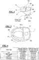
- Figure 4 shows the housing shell 8 oriented with the ear canal end 8A at the bottom and the faceplate end 8B at the top.
- This drawing figure shows the approximate 45 degree cut plane 22 described previously at the ear canal end 8A and indicates by dashed line 24 with three vertical slashes 50% of the canal width at the vent end 18A to show where the cut plane 22 begins for the approximate 45 degree cut.
- Figures 3 and 4 above show the design steps for the vent-as-large-as-possible wherein respective planar ruled surface cuts (cut planes) are used to maximize vent inlet/outlet areas.
- the software method of the preferred embodiment ensures that the vent-as-large-as-possible takes as much as possible space in the shell adhering to the constraints provided in the requirements (preference settings).
- the software provides the ability to place the vent-as-large-as-possible starter vent (regular round vent) inside the shell in the following manner:
- the software builds the vent-as-large-as-possible similar to a collection IROS (an IROS vent is an Ipsolateral Routing of Signal vent):
- Figure 5 shows a view of the vent-as-large-as-possible 18 inside the shell 8 at a cross-section shown in Fig. 3 at section line V-V at a lower part of the shell 8 near the ear canal end 8A.
- the receiver 7 is shown alongside the vent separator wall 18CC in free space 21.
- the software also provides for the following:
Description
- A vent (also referenced to herein as a "venting channel") is an important part of a hearing aid. A vent is required to provide air circulation and minimize occlusion. If a vent is not provided, a user will likely have an uneasy feeling caused by an unequal pressure differential present in a space between the user's ear drum and an inner ear canal end of the hearing aid housing compared to the atmospheric pressure external to the hearing aid housing outwardly of the ear. Users have described this uneasy feeling as an unnatural pressure differential. Users have also complained of what has been described as an unnatural hollow sound when the hearing aid is used if no vent is provided. Furthermore, care must be given in choosing the size of the vent since if the vent is too large, undesirable acoustic feedback may occur. When marketing experts in the hearing aid industry are asked which shell they would consider ideal, many of them will indicate a shell as small as possible, but with a vent as big as possible. The term "shell" used herein means an outermost wall of the hearing aid housing.
- A "collection vent" is a known prior art vent in hearing aids which starts as a regular round vent at a faceplate outer side of the hearing aid (also called a "starter vent" hereafter) and continues some distance as a round vent and then increases in diameter gradually until some size specified by a designer and which terminates at the canal side of the hearing aid near the ear drum.
-
EP 2 048 895 -
DE 11 2006 000463 discloses a waterproof hearing aid having waterproof films stretched over the inlet and outlet. The invention is defined in claim 1 and claim 11. Preferred embodiments are defined in the dependent claims. - It is an object to provide an automated software design method for a hearing aid which designs a vent-as-large-as-possible, and which takes as much space as possible in a housing shell of the hearing aid.
- A computerized method is provided for designing a vent in a hearing aid housing shell based on an image of a patient's ear canal impression, and
wherein a program is provided on a computer-readable medium. With the program, an image of a starter housing shell based on the image of the patient's ear canal impression is created which is longer than a final version of the housing shell to be created. A starter vent running from an inner canal end near the patient's ear drum to an outer end of the starter housing shell is placed inside the shell. Components are then placed substantially as deep as possible inside the starter shell but lying outside of the starter vent. Portions of the starter shell lying beyond where a faceplate is to be mounted are removed and the faceplate is mounted. The starter vent is then grown larger so that it fills substantially all space inside the shell without interfering with the components. -
-
Figure 1 is a flow chart of software in the computer for automatic creation of an optimized venting channel (vent) in a hearing aid instrument; -
Figure 2 is a perspective view of the hearing aid showing an outer housing shell and an outer end of a vent-as-large-as-possible running through the hearing aid; -
Figure 3 is a cross-sectional view taken along line III-III inFig. 2 showing a side profile of the hearing aid housing shell ofFigure 2 ; -
Figure 4 is a side perspective view of the hearing aid housing shell ofFig. 2 ; -
Figure 5 is a cross-sectional view taken along line V-V ofFig. 3 showing a portion of the vent-as-large-as-possible at the cross-section; and -
Figure 6 is a table showing vertically shell type and horizontally maximal and minimal cross-section size of the vent-as-large-as-possible for different shell types. - For the purposes of promoting an understanding of the principles of the invention, reference will now be made to the preferred embodiment illustrated in the drawings and specific language will be used to describe the same. It will nevertheless be understood that no limitation of the scope of the invention is thereby intended, and such alterations and further modifications in the illustrated device and such further applications of the principles of the invention as illustrated as would normally occur to one skilled in the art to which the invention relates are included.
- When the term "venting channel" or "vent" is used hereafter, it means a structure inside the shell that permits air flow between the inner ear canal near the ear drum and the outside atmosphere where the user is located.
- When the acronym CIC is used hereafter, it means completely-in-the-canal.
- A main goal is to provide an automated software design method which provides a vent of a biggest possible size, while having the shell of the hearing aid of a smallest possible size. A size of the shell is a more important constraint than a size of the vent. A big vent is desired by a patient to improve air circulation in the ear and to minimize the occlusion effect. The occlusion effect is minimized as the vent acoustic mass is decreased.
- The vent designed by the present software techniques of the preferred embodiment is hereinafter known as the "vent-as-large-as-possible" and alternately is also referred to as a "size-maximized vent".
- In a vent designed as-large-as-possible the occlusion effect is comprised of two major sub-functionalities:
- 1. building the vent-as-large-as-possible for a given location of the components; and
- 2. insuring insertability of components principally including a receiver in the shell.
- The
receiver 7 andother components 5 are located in the housing shell as shown inFig. 3 and discussed hereafter. The receiver emits sound into the ear of the patient via areceiver tube 7A which runs from areceiver spout 7B of thereceiver 7 where sound exits thereceiver 7, and runs from there to areceiver hole 6, which is a hole on theshell 8 close to anend 18A of thevent 18 at an innermost end of the housing shell near the ear drum as shown inFig. 3 . - As shown in
Fig. 1 , a flow chart 9 is provided for the automatic creation of an optimized venting channel (vent) in the hearing instrument by use of software run in a computer. In thefirst block 10, LOAD WORK ORDER, an order entry is received from a customer. A physical impression of a patient's ear canal is converted to a so-called "point cloud", which is a computer image data file of points on an outside surface of the physical impression. This point cloud data file is then loaded into the computer atblock 10. - At block 11, "DETAIL CANAL AND CREATE STARTER SHELL", from the point cloud data file a surface file is created by use of a plurality of triangles defined by adjacent point cloud triplets. This surface file describes a continuous outer surface of a starter version of the housing shell 8 (see
Figs. 2, 3 ). Unnecessary material is removed from the canal area of theend 8A of the shell near the ear canal. - At
block 12, "BUILD THE REGULAR ROUND VENT OF A MINIMAL CROSS-SECTION AS A STARTER VENT IN THE STARTER SHELL" the computer constructs an initial vent or what is known hereafter as a "starter"vent 3 which is preferably substantially round in cross-section of relatively small dimensions and runs from theend 8A of the starter shell 8 (Figs. 2, 3 ) nearest the ear drum to a starter end 8BB lying beyond theouter end 8B of the shell (seeFigs. 2, 3 ) where what is known as a faceplate 16 (Figs. 2, 3 , and4 ) is to be mounted in a later step. Thisregular round vent 3 is of an initial minimal size and represents a starting point for the software construction (starter vent). - In
block 13, "GO BACK TO DETAILING AND SHAPE THE STARTER SHELL AROUND WHERE THE FACEPLATE WILL BE MOUNTED USING VENT PREVIEW", a shape of anouter end 8B of the shell where thefaceplate 16 is to be provided is designed. As shown inFigs. 2, 3 , thefaceplate 16 glued on the shell will have anedge 16B adjacent to and defining one side of an aperture at anouter end 18B of thevent 18 open to the atmosphere, along with atrap door 19 with a finger-nail lift tab 19A which swings open for access to a battery. Other components such as a volume control and a push button, and amicrophone opening 20 are mounted on the faceplate. Note that the faceplate may contain or have mounted on it also other controls besides the microphone: push buttons, volume control, etc. Components including a hybrid, telecoil, reed switch, and anelectronics module 5 with battery are provided in a free space 21 (seeFig. 3 ) exterior to thevent 18 defined byvent wall 18C. The electronics module may be part of the faceplate or attached directly below it inspace 21. Thereceiver 7 is also provided down further inside the housing shell in thefree space 21. - In
block 13, the continuous shell surface is created using the previously mentioned triangulation technique. Material is also removed near the area where the faceplate is to be mounted to provide room for an opening for the vent and components to be mounted on the faceplate. - In
block 14, "GO TO THE COMPONENTS STEP AND FINALIZE LOCATION OF COMPONENTS AS DEEP AS POSSIBLE IN THE STARTER SHELL", the program does what is necessary to push the components as deep as possible into the starter housing shell without interfering with thestarter vent 3. - At
block 15, "REMOVE PORTIONS OF THE STARTER SHELL BEYOND WHERE THE FACEPLATE IS TO BE MOUNTED AND MOUNTING THE FACEPLATE", astarter shell portion 4 having starter shell end 8BB beyond where thefaceplate 16 is to be located are removed and thefaceplate 16 is mounted. - At
block 160, "GO TO THE NEXT STEP AND LET VENT TAKE UP SUBSTANTIALLY ALL FREE SPACE AVAILABLE TO CREATE THE VENT-AS-LARGE-AS POSSIBLE", an algorithm looks at theshell 8, the location of the components, and the location of the minimal round vent, and increases a size of thestarter vent 3 defined bywall 18C so that it occupies the space substantially not occupied by the components such asmodule 5 and thereceiver 7 withreceiver tube 7A which are situated infree space 21 inside the shell 8 (seeFigs. 2, 3 ). The thus maximizedvent 18 is shown by thevent wall 18C contour inFig. 3 . Note also that thevent wall 18C at a central region of the shell is part of a separating wall 18CC separating the vent-as-large-as-possible 18 from thefree space 21. Also note that thereceiver tube 7A running from thereceiver 7 down to thecanal end 8A of the shell near the ear drum lies just outside the separator wall 18CC partially defining the vent-as-large-as possible 18. Also noteelectronic cable 7D fromelectronics module 5 running down to thereceiver 7. - In
block 170, "SELECTIVE FILL AND LABELING", a selective fill and/or labeling is processed. Fill material is shown inFig. 3 at thecross-hatched regions 23. Note that selective fill and labeling are optional steps, and therefore can be skipped. -
Figs. 2 and 3 show the vent-as-large-as-possible at 18. At thecanal side end 8B of theshell 8, for the vent-as-large-as-possible 18 (nearest the eardrum) an operator of the software does a cut to create acut plane 22 identical to a cut currently performed for the known collection vent (regular round vent) previously described. On the faceplate side of the vent-as-large-as-possible shell, the operator does another cut to create anothercut plane 23 in order to accommodate thelarge outlet end 18B of the vent-as-large-as possible 18. Here thefaceplate 16 hasside edge 16B defining one side of thevent 18 aperture at theend 18B. This is shown inFigs. 2 and 3 . -
Fig. 3 will now be described in more detail.Fig. 3 shows thehousing shell 8 with theend 8A closest to the ear drum at the bottom and theend 8B at thefaceplate 16 at the top after removal of the portion 4 (shown in dashed lines) of thestarter shell 8. Components of the hearing aid such as theelectronics module 5 are shown in this drawing figure inspace 21. The 45 degree cutplane 22 is provided oncurved surface 19 at the housingshell canal side 8A at the bottom. The region orfree space 21 shows where theelectronics module 5 andreceiver 7 are to be housed. The substantially horizontal rectangle panel illustrated at the top is thefaceplate 16. Note that during the shell assembly after the faceplate is glued to the shell allfaceplate material 16A outside of the shell is trimmed away. Thetrap door 19 withfinger nail protrusion 19A is shown at the top of thefaceplate 16. The twocut planes plane 22 described above, and thesecond cut plane 23 is shown atedge 16B of thefaceplate 16 at the left side of the drawing and slanting slightly down fromedge 16B. Note that other angles of cuts are also acceptable. The vent-as-large-as-possible 18 is defined by thevent wall 18C inFig. 3 and runs from thissecond cut plane 23 next to theedge 16B of thefaceplate 16 at theoutside end 18B of the vent, down to the 45 degree cutplane 22, which is thevent end 18A at the canal side near the eardrum. Thetop cut plane 23 next to thefaceplate 16 atedge 16B is called a low angle cut plane. - The material shown as cross-hatching in
Fig. 3 and exterior to thevent wall 18C is either part of thehousing shell 8 or the separator wall 18CC. - Where the cut planes are provided depends upon a location of electronics such as
electronics module 5, optional components,receiver 7,receiver hole 6,receiver tube 7A, and values of different preferences parameters that define a shape of thevent 18, ventend 18A and ventend 18B. - Vent design for the vent-as-large-as-possible of the preferred embodiment is very different from vent design for the previously mentioned prior art collection vent. A main difference is that for the collection vent design, an algorithm finds just a biggest contour that can accommodate the vent inlet. In the case of the vent-as-large-as-possible of the preferred embodiment herein, the vent inlet contour can be smaller than the vent inlet for the collection vent, because one needs to avoid collisions with the components and receiver hole, and adhere to other preferences settings not used for the collection vent. Another important difference between the existing prior art vents and the new vent-as-large-as-possible is that prior art vents are built without any consideration of component positions. The vent is built first, and then components are placed into the shell in the prior art. In the vent-as-large-as-possible first the starter vent is placed, then components such as volume control, push button, receiver, electronics module with battery, and microphone are placed as deep as possible in the starter shell, then the starter shell is cut to remove portions beyond where the faceplate is to be located, and then the starter vent is transformed into the vent-as-large as possible.
- The shape of the vent end at 18A and vent end at 18B in
Fig. 3 is defined following preferences settings. The term "preferences settings" means for the design software of the present preferred embodiment, the particular parameters chosen by the operator defining how different algorithms in the software perform functions. -
Figure 4 shows thehousing shell 8 oriented with theear canal end 8A at the bottom and thefaceplate end 8B at the top. This drawing figure shows the approximate 45 degree cutplane 22 described previously at theear canal end 8A and indicates by dashedline 24 with threevertical slashes 50% of the canal width at the vent end 18A to show where thecut plane 22 begins for the approximate 45 degree cut. -
Figures 3 and4 above show the design steps for the vent-as-large-as-possible wherein respective planar ruled surface cuts (cut planes) are used to maximize vent inlet/outlet areas. - The workflow for vent placement design by the software for the vent-as-large-as-possible will again be described, but with some additional details with reference to
Fig. 1 : - 1. detail canal (
Fig 1 - block 11); - 2. go to vent step and place a starter vent, which is in a preferred embodiment a regular round vent (
Fig. 1 - block 12), possibly accompanied with canal tip modification, receiver and receiver hole placement - the starter vent is preferably the regular round vent of minimal cross-section; - 3. go back to detailing, starter vent preview shown during the detailing (
Fig. 1 - block 13); - 4. place electronics, hybrid, optional components and finish detailing - trim shell around the faceplate (
Fig. 1 - block 14); - 5. go to the faceplate mounting step (
Fig. 1 - block 15) and after the faceplate mounting step the starter vent (regular round vent -block 12 inFig. 1 ) is replaced with the vent-as-large-as-possible (Fig. 1 - block 160); and - 6. proceed to a selective fill and/or labeling step (
Fig. 1 - block 170 - a selective fill and labeling) which is selecting an area with a plane and filling it with material, and the labeling is the step of assigning an identification for the shell by engraving or embossing on an inside surface of the shell housing. - The software method of the preferred embodiment ensures that the vent-as-large-as-possible takes as much as possible space in the shell adhering to the constraints provided in the requirements (preference settings).
- The software provides the ability to place the vent-as-large-as-possible starter vent (regular round vent) inside the shell in the following manner:
- A. a starter section (regular round vent) is equal to a minimal cross-section area of the vent-as-large-as-possible defined in the preferences - for example if the minimal cross-section area as defined in the preferences is S, then a radius of a regular round vent is computed from the formula S=PI*r^2, where r is the radius of the regular vent, and PI is 3.1415926;
- B. a vent is always shown during a preview in detailing the vent-as-large-as-possible if the user has already placed the starter vent (regular round vent);
- C. the software does not show the vent at all during the vent preview - in detailing the user has not yet placed the starter vent (regular round vent) for the vent-as-large-as-possible;
- D. the software allows the user to place the starter vent (regular round vent) during the vent step - the software generates the vent-as-large-as-possible from the starter vent (regular round vent); and
- E. The software builds the vent-as-large-as-possible on all shell types (CIC, Mini-Canal, Canal, Half-Shell, Full-Shell).
- The software builds the vent-as-large-as-possible similar to a collection IROS (an IROS vent is an Ipsolateral Routing of Signal vent):
- A. in the preferences the settings are provided for a maximal curvature of the vent end 18A wall - the software ensures that the inlet end 18A wall of the vent-as-large-as-possible does not violate a maximal curvature of the vent inlet end 18A wall defined in the preferences;
- B. in the preferences the settings are provided for the maximal curvature of the
vent outlet end 18B wall - the software ensures that theoutlet 18B wall of the vent-as-large-as-possible does not violate the maximal curvature of thevent outlet end 18B wall defined in the preferences; and - C. the software builds the vent-as-large-as-possible inside the
shell 8 similarly to a non-continuous D-shape vent as a straight segment with optional connecting segments - a D-shape vent is a vent which is built as a wall inside the shell with openings at the faceplate and the canal side, - normally this vent has a shape of a "D". -
Figure 5 shows a view of the vent-as-large-as-possible 18 inside theshell 8 at a cross-section shown inFig. 3 at section line V-V at a lower part of theshell 8 near theear canal end 8A. Thereceiver 7 is shown alongside the vent separator wall 18CC infree space 21. - The software of the preferred embodiment ensures or provides the following:
- A. that the vent-as-large-as-possible has no collisions with any of the components (including receiver hole 6);
- B. in the preferences, settings are provided for minimal cross-section area inside the vent in mm2;
- C. in the preferences, the settings are provided for maximal cross-section area inside the vent in mm2;
- D. in the preferences, different settings are provided for the vent-as-large-as-possible minimal and maximal cross-section area depending upon the shell type - this vent-as-large-as-possible minimal cross-section depending on the shell type is shown in
Fig. 6 which shows a table of shell type indicated vertically and maximal cross-section and minimal cross-section that the software could adhere to indicated horizontally; - E. the
vent inlet end 18A and outlet end 18B for the vent-as-large-as-possible 18 does not go outside the suggested vent inlet and outlet cutplanes - F. in the preferences the settings are provided for maximal allowed absolute gradient of two adjacent vent cross-section areas; and
- G. the vent-as-large-as-possible generation algorithm (
Fig. 1 - block 160) ensures that an absolute gradient of adjacent vent slice areas is lower than a preference value - a gradient of adjacent vent slice areas is calculated as (a2-a1)/d, where a2 and a1 are areas of adjacent cross-sections, and d is a distance between cross-sections - if the absolute gradient of adjacent cross-section areas is higher than certain thresholds than this means that in these particular cross-sections the vent makes a large bend - it is desirable that the vent be smooth, therefore with the maximal and minimal ratio one is able to control the smoothness of the vent. - The software also provides for the following:
- A. ensures that the
hearing aid receiver 7 can be inserted into theshell 8 up to its final location given the vent-as-large-as-possible 18 placement; - B. ensures that the vent generation algorithm does not modify a position of components during the vent-as-large-as-possible 18 integration;
- C. allows the user to apply the vent-as-large-as-possible 18 with one mouse click, provided that the starter vent (regular round vent) is already placed - the user interface comprises one button that applies the vent-as-large-as-possible, or the user may go from the faceplate step (
Fig. 1 - block 15) to the selective fill step (Fig. 1 - block 170) and the vent-as-large-as-possible may be applied; - D. allows the user to remove the vent-as-large-as-possible 18 from the
shell 8 if no other operation has been applied to theshell 8 after the vent-as-large-as-possible 18 is placed - this can be implemented with an undo button; - E. does not allow adaptive vent tapering on the vent-as-large-as-possible 18 (although the resulting
shell 8 of the vent-as-large-as-possible 18 may look similar on the vent inlet end 18A side to the adaptive vent tapering); - F. allows to put into a script file the placement of the vent-as-large-as-possible 18 starter vent (regular round vent);
- G. allows the user to position the
receiver 7, electronics, hybrid and all optional components prior to the generation of the vent-as-large-as-possible 18 from the starter vent (regular round vent) - the user is not allowed to position thereceiver 7, electronics, hybrid and all optional components after the generation of the vent-as-large-as-possible from the starter vent (regular round vent); and - H. does not allow the vent-as-large-as-possible 18 in a combination with RSA (RSA means Receiver Suspension Assembly which is a series of design steps for receiver placement).
- While a preferred embodiment has been illustrated and described in detail in the drawings and foregoing description, the same is to be considered as illustrative and not restrictive in character, it being understood that only the preferred embodiment has been shown and described and that all changes and modifications that come within the spirit of the invention both now or in the future are desired to be protected.
Claims (11)
- A computerized method for designing a vent (18) in a hearing aid housing shell to be created based on an image of a patient's ear canal and wherein a program is provided on a computer-readable medium run on a computer, said program performing the steps of:creating an image of a starter housing shell (4) based on the patient's ear canal impression which image is longer than a final version of the hearing aid housing shell (8) to be created;placing a starter vent (3) inside the starter housing shell (4), the starter vent running from an inner canal end near the patient's ear drum to an outer end of the starter housing shell;placing components (5,7) substantially as deep as possible inside the starter housing shell but lying outside of the starter vent;removing portions of the starter housing shell beyond where a faceplate (16) is to be mounted and mounting the faceplate; andgrowing the starter vent (3) larger so that it fills substantially all space inside the hearing aid housing shell without interfering with said components.
- A method of claim 1 wherein the starter vent comprises a substantially round vent.
- A method of claim 1 wherein the vent, which is grown larger, has its one end at said inner canal end of the housing shell defined by a first cut plane (22) and has its other end at the faceplate defined by a second cut plane (23).
- A method of claim 3 wherein said first cut plane is approximately a 45 degree cut with respect to a plane of a faceplate at the faceplate end and said second cut plane is a cut resulting in a slight slope next to an edge of said faceplate at said faceplate end of the hearing aid housing shell.
- A method of claim 1 wherein the components inside the starter hosing shell comprise a receiver (7) having a receiver tube connected thereto extending to a receiver hole at said inner canal end of the housing shell and wherein said receiver hole lies adjacent to an end of the vent at said shell inner canal end.
- A method of claim 1 wherein prior to growing the starter vent larger, the hearing aid housing shell at said faceplate end is adapted to receive a faceplate.
- A method of claim 1 wherein the starter vent is placed before placing the components in the starter housing shell.
- A method of claim 1 wherein a shape of the hearing aid housing shell at the faceplate end is shaped for the faceplate before final component placement but after placement of the starter vent.
- A method of claim 1 wherein to create the image of the starter housing shell, the patient ear impression is defined by a point cloud and then utilizing adjacent three points of the point cloud a continuous surface is defined for the hearing aid housing shell.
- A method of claim 1 wherein the shell comprises a separator wall defining a first and second space alongside thereof, those components which are not part of the faceplate lie in the first space and the starter vent lies in the second space, the separator wall partially defining the vent that has been grown larger.
- A computer-readable medium comprising a program for designing a vent (18) in a hearing aid housing shell (4) based on an image of a patient's ear canal, said program performing the steps of:creating an image of a starter housing shell based on the patient's ear canal impression which image is larger than a final version of the hearing aide housing shell to be created;placing a starter vent (3) inside the starter housing shell, the starter vent running from an inner canal end near the patient's ear drum to an outer end of the starter housing shell ;placing components (5,7) substantially as deep as possible inside the starter housing shell but lying outside of the starter vent;removing portions of the starter housing shell beyond where a faceplate (16) is to be mounted and mounting the faceplate; andgrowing the starter vent larger so that it fills substantially all space inside the starter housing shell without interfering with said components.
Applications Claiming Priority (1)
| Application Number | Priority Date | Filing Date | Title |
|---|---|---|---|
| US12/436,834 US8554352B2 (en) | 2009-05-07 | 2009-05-07 | Method of generating an optimized venting channel in a hearing instrument |
Publications (3)
| Publication Number | Publication Date |
|---|---|
| EP2249585A2 EP2249585A2 (en) | 2010-11-10 |
| EP2249585A3 EP2249585A3 (en) | 2014-02-26 |
| EP2249585B1 true EP2249585B1 (en) | 2017-12-27 |
Family
ID=42635241
Family Applications (1)
| Application Number | Title | Priority Date | Filing Date |
|---|---|---|---|
| EP10161061.6A Not-in-force EP2249585B1 (en) | 2009-05-07 | 2010-04-26 | Method of generating an optimized venting channel in a hearing instrument |
Country Status (3)
| Country | Link |
|---|---|
| US (1) | US8554352B2 (en) |
| EP (1) | EP2249585B1 (en) |
| DK (1) | DK2249585T3 (en) |
Families Citing this family (6)
| Publication number | Priority date | Publication date | Assignee | Title |
|---|---|---|---|---|
| RU2012119267A (en) * | 2009-10-16 | 2013-11-27 | Зшейп А/С | INDIVIDUALLY DESIGNED ELEMENT FROM SOFT MATERIAL |
| WO2011107445A1 (en) * | 2010-03-04 | 2011-09-09 | Bayer Cropscience Ag | Hydrate and anhydrous crystal form of the sodium salt of 2-iodo-n-[(4-methoxy-6-methyl-1,3,5-triazin-2-yl)carbamoyl]benzenesulfonamide, process for preparation thereof and use thereof as herbicides and plant growth regulators |
| US10129668B2 (en) * | 2013-12-31 | 2018-11-13 | Gn Hearing A/S | Earmold for active occlusion cancellation |
| US9820064B1 (en) * | 2016-06-29 | 2017-11-14 | Daniel R. Schumaier | Method for manufacturing custom in-ear monitor with decorative faceplate |
| US10986432B2 (en) * | 2017-06-30 | 2021-04-20 | Bose Corporation | Customized ear tips |
| EP4002883A1 (en) | 2020-11-23 | 2022-05-25 | Sonova AG | Automated sensor position determination for hearing device housing |
Family Cites Families (25)
| Publication number | Priority date | Publication date | Assignee | Title |
|---|---|---|---|---|
| US5487012A (en) * | 1990-12-21 | 1996-01-23 | Topholm & Westermann Aps | Method of preparing an otoplasty or adaptive earpiece individually matched to the shape of an auditory canal |
| US7050876B1 (en) * | 2000-10-06 | 2006-05-23 | Phonak Ltd. | Manufacturing methods and systems for rapid production of hearing-aid shells |
| US8032337B2 (en) * | 2001-03-02 | 2011-10-04 | 3Shape A/S | Method for modeling customized earpieces |
| EP1246506A1 (en) * | 2001-03-26 | 2002-10-02 | Widex A/S | A CAD/CAM system for designing a hearing aid |
| EP1246505A1 (en) * | 2001-03-26 | 2002-10-02 | Widex A/S | A hearing aid with a face plate that is automatically manufactured to fit the hearing aid shell |
| EP1246507A1 (en) * | 2001-03-26 | 2002-10-02 | Widex A/S | A hearing aid with a tightening ring |
| US20020196954A1 (en) * | 2001-06-22 | 2002-12-26 | Marxen Christopher J. | Modeling and fabrication of three-dimensional irregular surfaces for hearing instruments |
| US6731997B2 (en) * | 2001-07-26 | 2004-05-04 | Phonak Ag | Method for manufacturing hearing devices |
| EP1465458A3 (en) * | 2003-04-03 | 2006-05-24 | Gennum Corporation | Hearing instrument vent |
| US7555356B2 (en) * | 2003-04-03 | 2009-06-30 | Phonak Ag | Method for manufacturing a body-worn electronic device adapted to the shape of an individual's body area |
| US20050088435A1 (en) * | 2003-10-23 | 2005-04-28 | Z. Jason Geng | Novel 3D ear camera for making custom-fit hearing devices for hearing aids instruments and cell phones |
| JP3866748B2 (en) * | 2005-02-22 | 2007-01-10 | リオン株式会社 | Waterproof hearing aid |
| US7447556B2 (en) * | 2006-02-03 | 2008-11-04 | Siemens Audiologische Technik Gmbh | System comprising an automated tool and appertaining method for hearing aid design |
| US7991594B2 (en) * | 2005-09-13 | 2011-08-02 | Siemens Corporation | Method and apparatus for the rigid registration of 3D ear impression shapes with skeletons |
| US7979244B2 (en) * | 2005-09-13 | 2011-07-12 | Siemens Corporation | Method and apparatus for aperture detection of 3D hearing aid shells |
| US8086427B2 (en) * | 2005-09-13 | 2011-12-27 | Siemens Corporation | Method and apparatus for the registration of 3D ear impression models |
| US8135453B2 (en) * | 2005-12-07 | 2012-03-13 | Siemens Corporation | Method and apparatus for ear canal surface modeling using optical coherence tomography imaging |
| US8150542B2 (en) * | 2006-06-14 | 2012-04-03 | Phonak Ag | Positioning and orienting a unit of a hearing device relative to individual's head |
| US7672823B2 (en) * | 2006-09-05 | 2010-03-02 | Siemens Aktiengesellschaft | Computerized method for adherence to physical restriction in the construction of an ITE hearing aid |
| US7609259B2 (en) * | 2006-10-18 | 2009-10-27 | Siemens Audiologische Technik Gmbh | System and method for performing a selective fill for a hearing aid shell |
| US8180085B2 (en) * | 2007-08-27 | 2012-05-15 | Siemens Hearing Instruments, Inc. | Assembly procedure for CIC with floating components |
| US20090097682A1 (en) * | 2007-10-12 | 2009-04-16 | Siemens Hearing Instruments Inc. | Computerized rule based binaural modeling system for the hearing aid design |
| US8065118B2 (en) * | 2007-10-16 | 2011-11-22 | Siemens Hearing Instruments Inc. | Method for anatomically aware automatic faceplate placement for hearing instrument design |
| US8265316B2 (en) * | 2008-03-20 | 2012-09-11 | Siemens Medical Instruments Pte. Ltd. | Hearing aid with enhanced vent |
| US8199952B2 (en) * | 2008-04-01 | 2012-06-12 | Siemens Hearing Instruments, Inc. | Method for adaptive construction of a small CIC hearing instrument |
-
2009
- 2009-05-07 US US12/436,834 patent/US8554352B2/en not_active Expired - Fee Related
-
2010
- 2010-04-26 DK DK10161061.6T patent/DK2249585T3/en active
- 2010-04-26 EP EP10161061.6A patent/EP2249585B1/en not_active Not-in-force
Non-Patent Citations (1)
| Title |
|---|
| None * |
Also Published As
| Publication number | Publication date |
|---|---|
| DK2249585T3 (en) | 2018-04-16 |
| EP2249585A3 (en) | 2014-02-26 |
| EP2249585A2 (en) | 2010-11-10 |
| US20100286964A1 (en) | 2010-11-11 |
| US8554352B2 (en) | 2013-10-08 |
Similar Documents
| Publication | Publication Date | Title |
|---|---|---|
| EP2107832B1 (en) | A method for adaptive construction of a small CIC hearing instrument | |
| EP2249585B1 (en) | Method of generating an optimized venting channel in a hearing instrument | |
| EP2432255B1 (en) | Hearing instrument | |
| US8437489B2 (en) | Hearing instrument | |
| US20020196954A1 (en) | Modeling and fabrication of three-dimensional irregular surfaces for hearing instruments | |
| US8332061B2 (en) | Feature driven rule-based framework for automation of modeling workflows in digital manufacturing | |
| EP1356709B1 (en) | Manufacturing methods and systems for rapid production of hearing-aid shells | |
| EP2181551B1 (en) | Fitting procedure for hearing devices and corresponding hearing device | |
| US7801708B2 (en) | Method and apparatus for the rigid and non-rigid registration of 3D shapes | |
| EP2098097B1 (en) | Hearing instrument with user interface | |
| US20140172042A1 (en) | Optimizing operational control of a hearing prosthesis | |
| US20110096948A1 (en) | Hearing instrument comprising a divided wax filter | |
| US20220070573A1 (en) | Dome for hearing aids | |
| US20060233384A1 (en) | Method of manufacturing an individually shaped hearing device or hearing aid | |
| EP2919486A1 (en) | Method for producing hearing aid fittings | |
| EP2048895B1 (en) | A computerized rule-based binaural modeling system and method for hearing aid design | |
| US8065118B2 (en) | Method for anatomically aware automatic faceplate placement for hearing instrument design | |
| US11082781B2 (en) | Ear piece with active vent control | |
| US20180124531A1 (en) | Hearing Aid Sleeve | |
| JP2020184746A (en) | Hearing device having vent | |
| CN112995877A (en) | Method of manufacturing a combination for a hearing device | |
| US8494814B2 (en) | Methods for inlet and outlet modelling of vent as large as possible for hearing aid devices | |
| EP1558058B1 (en) | Method of manufacturing and individually shaped hearing device or hearing aid | |
| JP7220529B2 (en) | Manufacturing method of earmold and manufacturing method of cartilage conduction hearing aid | |
| EP4002883A1 (en) | Automated sensor position determination for hearing device housing |
Legal Events
| Date | Code | Title | Description |
|---|---|---|---|
| PUAI | Public reference made under article 153(3) epc to a published international application that has entered the european phase |
Free format text: ORIGINAL CODE: 0009012 |
|
| AK | Designated contracting states |
Kind code of ref document: A2 Designated state(s): AT BE BG CH CY CZ DE DK EE ES FI FR GB GR HR HU IE IS IT LI LT LU LV MC MK MT NL NO PL PT RO SE SI SK SM TR |
|
| AX | Request for extension of the european patent |
Extension state: AL BA ME RS |
|
| PUAL | Search report despatched |
Free format text: ORIGINAL CODE: 0009013 |
|
| AK | Designated contracting states |
Kind code of ref document: A3 Designated state(s): AT BE BG CH CY CZ DE DK EE ES FI FR GB GR HR HU IE IS IT LI LT LU LV MC MK MT NL NO PL PT RO SE SI SK SM TR |
|
| AX | Request for extension of the european patent |
Extension state: AL BA ME RS |
|
| RIC1 | Information provided on ipc code assigned before grant |
Ipc: H04R 25/00 20060101AFI20140121BHEP Ipc: H04R 25/02 20060101ALI20140121BHEP |
|
| 17P | Request for examination filed |
Effective date: 20140805 |
|
| RBV | Designated contracting states (corrected) |
Designated state(s): AT BE BG CH CY CZ DE DK EE ES FI FR GB GR HR HU IE IS IT LI LT LU LV MC MK MT NL NO PL PT RO SE SI SK SM TR |
|
| RAP1 | Party data changed (applicant data changed or rights of an application transferred) |
Owner name: SIVANTOS, INC. |
|
| GRAP | Despatch of communication of intention to grant a patent |
Free format text: ORIGINAL CODE: EPIDOSNIGR1 |
|
| INTG | Intention to grant announced |
Effective date: 20170714 |
|
| GRAS | Grant fee paid |
Free format text: ORIGINAL CODE: EPIDOSNIGR3 |
|
| GRAA | (expected) grant |
Free format text: ORIGINAL CODE: 0009210 |
|
| AK | Designated contracting states |
Kind code of ref document: B1 Designated state(s): AT BE BG CH CY CZ DE DK EE ES FI FR GB GR HR HU IE IS IT LI LT LU LV MC MK MT NL NO PL PT RO SE SI SK SM TR |
|
| REG | Reference to a national code |
Ref country code: GB Ref legal event code: FG4D |
|
| REG | Reference to a national code |
Ref country code: CH Ref legal event code: EP |
|
| REG | Reference to a national code |
Ref country code: AT Ref legal event code: REF Ref document number: 959273 Country of ref document: AT Kind code of ref document: T Effective date: 20180115 |
|
| REG | Reference to a national code |
Ref country code: IE Ref legal event code: FG4D |
|
| REG | Reference to a national code |
Ref country code: CH Ref legal event code: NV Representative=s name: E. BLUM AND CO. AG PATENT- UND MARKENANWAELTE , CH |
|
| REG | Reference to a national code |
Ref country code: DE Ref legal event code: R096 Ref document number: 602010047605 Country of ref document: DE |
|
| REG | Reference to a national code |
Ref country code: DK Ref legal event code: T3 Effective date: 20180410 |
|
| REG | Reference to a national code |
Ref country code: FR Ref legal event code: PLFP Year of fee payment: 9 |
|
| PG25 | Lapsed in a contracting state [announced via postgrant information from national office to epo] |
Ref country code: NO Free format text: LAPSE BECAUSE OF FAILURE TO SUBMIT A TRANSLATION OF THE DESCRIPTION OR TO PAY THE FEE WITHIN THE PRESCRIBED TIME-LIMIT Effective date: 20180327 Ref country code: LT Free format text: LAPSE BECAUSE OF FAILURE TO SUBMIT A TRANSLATION OF THE DESCRIPTION OR TO PAY THE FEE WITHIN THE PRESCRIBED TIME-LIMIT Effective date: 20171227 Ref country code: FI Free format text: LAPSE BECAUSE OF FAILURE TO SUBMIT A TRANSLATION OF THE DESCRIPTION OR TO PAY THE FEE WITHIN THE PRESCRIBED TIME-LIMIT Effective date: 20171227 |
|
| REG | Reference to a national code |
Ref country code: NL Ref legal event code: MP Effective date: 20171227 |
|
| REG | Reference to a national code |
Ref country code: LT Ref legal event code: MG4D |
|
| REG | Reference to a national code |
Ref country code: AT Ref legal event code: MK05 Ref document number: 959273 Country of ref document: AT Kind code of ref document: T Effective date: 20171227 |
|
| PG25 | Lapsed in a contracting state [announced via postgrant information from national office to epo] |
Ref country code: HR Free format text: LAPSE BECAUSE OF FAILURE TO SUBMIT A TRANSLATION OF THE DESCRIPTION OR TO PAY THE FEE WITHIN THE PRESCRIBED TIME-LIMIT Effective date: 20171227 Ref country code: GR Free format text: LAPSE BECAUSE OF FAILURE TO SUBMIT A TRANSLATION OF THE DESCRIPTION OR TO PAY THE FEE WITHIN THE PRESCRIBED TIME-LIMIT Effective date: 20180328 Ref country code: BG Free format text: LAPSE BECAUSE OF FAILURE TO SUBMIT A TRANSLATION OF THE DESCRIPTION OR TO PAY THE FEE WITHIN THE PRESCRIBED TIME-LIMIT Effective date: 20180327 Ref country code: LV Free format text: LAPSE BECAUSE OF FAILURE TO SUBMIT A TRANSLATION OF THE DESCRIPTION OR TO PAY THE FEE WITHIN THE PRESCRIBED TIME-LIMIT Effective date: 20171227 |
|
| PG25 | Lapsed in a contracting state [announced via postgrant information from national office to epo] |
Ref country code: NL Free format text: LAPSE BECAUSE OF FAILURE TO SUBMIT A TRANSLATION OF THE DESCRIPTION OR TO PAY THE FEE WITHIN THE PRESCRIBED TIME-LIMIT Effective date: 20171227 |
|
| PG25 | Lapsed in a contracting state [announced via postgrant information from national office to epo] |
Ref country code: CZ Free format text: LAPSE BECAUSE OF FAILURE TO SUBMIT A TRANSLATION OF THE DESCRIPTION OR TO PAY THE FEE WITHIN THE PRESCRIBED TIME-LIMIT Effective date: 20171227 Ref country code: EE Free format text: LAPSE BECAUSE OF FAILURE TO SUBMIT A TRANSLATION OF THE DESCRIPTION OR TO PAY THE FEE WITHIN THE PRESCRIBED TIME-LIMIT Effective date: 20171227 Ref country code: CY Free format text: LAPSE BECAUSE OF FAILURE TO SUBMIT A TRANSLATION OF THE DESCRIPTION OR TO PAY THE FEE WITHIN THE PRESCRIBED TIME-LIMIT Effective date: 20171227 Ref country code: ES Free format text: LAPSE BECAUSE OF FAILURE TO SUBMIT A TRANSLATION OF THE DESCRIPTION OR TO PAY THE FEE WITHIN THE PRESCRIBED TIME-LIMIT Effective date: 20171227 Ref country code: SK Free format text: LAPSE BECAUSE OF FAILURE TO SUBMIT A TRANSLATION OF THE DESCRIPTION OR TO PAY THE FEE WITHIN THE PRESCRIBED TIME-LIMIT Effective date: 20171227 |
|
| PG25 | Lapsed in a contracting state [announced via postgrant information from national office to epo] |
Ref country code: IT Free format text: LAPSE BECAUSE OF FAILURE TO SUBMIT A TRANSLATION OF THE DESCRIPTION OR TO PAY THE FEE WITHIN THE PRESCRIBED TIME-LIMIT Effective date: 20171227 Ref country code: RO Free format text: LAPSE BECAUSE OF FAILURE TO SUBMIT A TRANSLATION OF THE DESCRIPTION OR TO PAY THE FEE WITHIN THE PRESCRIBED TIME-LIMIT Effective date: 20171227 Ref country code: IS Free format text: LAPSE BECAUSE OF FAILURE TO SUBMIT A TRANSLATION OF THE DESCRIPTION OR TO PAY THE FEE WITHIN THE PRESCRIBED TIME-LIMIT Effective date: 20180427 Ref country code: SM Free format text: LAPSE BECAUSE OF FAILURE TO SUBMIT A TRANSLATION OF THE DESCRIPTION OR TO PAY THE FEE WITHIN THE PRESCRIBED TIME-LIMIT Effective date: 20171227 Ref country code: AT Free format text: LAPSE BECAUSE OF FAILURE TO SUBMIT A TRANSLATION OF THE DESCRIPTION OR TO PAY THE FEE WITHIN THE PRESCRIBED TIME-LIMIT Effective date: 20171227 Ref country code: PL Free format text: LAPSE BECAUSE OF FAILURE TO SUBMIT A TRANSLATION OF THE DESCRIPTION OR TO PAY THE FEE WITHIN THE PRESCRIBED TIME-LIMIT Effective date: 20171227 |
|
| REG | Reference to a national code |
Ref country code: DE Ref legal event code: R097 Ref document number: 602010047605 Country of ref document: DE |
|
| PLBE | No opposition filed within time limit |
Free format text: ORIGINAL CODE: 0009261 |
|
| STAA | Information on the status of an ep patent application or granted ep patent |
Free format text: STATUS: NO OPPOSITION FILED WITHIN TIME LIMIT |
|
| PG25 | Lapsed in a contracting state [announced via postgrant information from national office to epo] |
Ref country code: MC Free format text: LAPSE BECAUSE OF FAILURE TO SUBMIT A TRANSLATION OF THE DESCRIPTION OR TO PAY THE FEE WITHIN THE PRESCRIBED TIME-LIMIT Effective date: 20171227 |
|
| 26N | No opposition filed |
Effective date: 20180928 |
|
| REG | Reference to a national code |
Ref country code: BE Ref legal event code: MM Effective date: 20180430 |
|
| REG | Reference to a national code |
Ref country code: IE Ref legal event code: MM4A |
|
| PG25 | Lapsed in a contracting state [announced via postgrant information from national office to epo] |
Ref country code: LU Free format text: LAPSE BECAUSE OF NON-PAYMENT OF DUE FEES Effective date: 20180426 |
|
| PG25 | Lapsed in a contracting state [announced via postgrant information from national office to epo] |
Ref country code: BE Free format text: LAPSE BECAUSE OF NON-PAYMENT OF DUE FEES Effective date: 20180430 Ref country code: SI Free format text: LAPSE BECAUSE OF FAILURE TO SUBMIT A TRANSLATION OF THE DESCRIPTION OR TO PAY THE FEE WITHIN THE PRESCRIBED TIME-LIMIT Effective date: 20171227 |
|
| PG25 | Lapsed in a contracting state [announced via postgrant information from national office to epo] |
Ref country code: IE Free format text: LAPSE BECAUSE OF NON-PAYMENT OF DUE FEES Effective date: 20180426 |
|
| PGFP | Annual fee paid to national office [announced via postgrant information from national office to epo] |
Ref country code: DK Payment date: 20190425 Year of fee payment: 10 Ref country code: DE Payment date: 20190418 Year of fee payment: 10 |
|
| PGFP | Annual fee paid to national office [announced via postgrant information from national office to epo] |
Ref country code: FR Payment date: 20190423 Year of fee payment: 10 |
|
| PGFP | Annual fee paid to national office [announced via postgrant information from national office to epo] |
Ref country code: CH Payment date: 20190424 Year of fee payment: 10 |
|
| PGFP | Annual fee paid to national office [announced via postgrant information from national office to epo] |
Ref country code: GB Payment date: 20190424 Year of fee payment: 10 |
|
| PG25 | Lapsed in a contracting state [announced via postgrant information from national office to epo] |
Ref country code: MT Free format text: LAPSE BECAUSE OF NON-PAYMENT OF DUE FEES Effective date: 20180426 |
|
| PG25 | Lapsed in a contracting state [announced via postgrant information from national office to epo] |
Ref country code: TR Free format text: LAPSE BECAUSE OF FAILURE TO SUBMIT A TRANSLATION OF THE DESCRIPTION OR TO PAY THE FEE WITHIN THE PRESCRIBED TIME-LIMIT Effective date: 20171227 |
|
| PG25 | Lapsed in a contracting state [announced via postgrant information from national office to epo] |
Ref country code: HU Free format text: LAPSE BECAUSE OF FAILURE TO SUBMIT A TRANSLATION OF THE DESCRIPTION OR TO PAY THE FEE WITHIN THE PRESCRIBED TIME-LIMIT; INVALID AB INITIO Effective date: 20100426 Ref country code: PT Free format text: LAPSE BECAUSE OF FAILURE TO SUBMIT A TRANSLATION OF THE DESCRIPTION OR TO PAY THE FEE WITHIN THE PRESCRIBED TIME-LIMIT Effective date: 20171227 |
|
| PG25 | Lapsed in a contracting state [announced via postgrant information from national office to epo] |
Ref country code: MK Free format text: LAPSE BECAUSE OF NON-PAYMENT OF DUE FEES Effective date: 20171227 Ref country code: SE Free format text: LAPSE BECAUSE OF FAILURE TO SUBMIT A TRANSLATION OF THE DESCRIPTION OR TO PAY THE FEE WITHIN THE PRESCRIBED TIME-LIMIT Effective date: 20171227 |
|
| REG | Reference to a national code |
Ref country code: DE Ref legal event code: R119 Ref document number: 602010047605 Country of ref document: DE |
|
| REG | Reference to a national code |
Ref country code: DK Ref legal event code: EBP Effective date: 20200430 |
|
| REG | Reference to a national code |
Ref country code: CH Ref legal event code: PL |
|
| PG25 | Lapsed in a contracting state [announced via postgrant information from national office to epo] |
Ref country code: CH Free format text: LAPSE BECAUSE OF NON-PAYMENT OF DUE FEES Effective date: 20200430 Ref country code: DE Free format text: LAPSE BECAUSE OF NON-PAYMENT OF DUE FEES Effective date: 20201103 Ref country code: LI Free format text: LAPSE BECAUSE OF NON-PAYMENT OF DUE FEES Effective date: 20200430 Ref country code: FR Free format text: LAPSE BECAUSE OF NON-PAYMENT OF DUE FEES Effective date: 20200430 |
|
| GBPC | Gb: european patent ceased through non-payment of renewal fee |
Effective date: 20200426 |
|
| PG25 | Lapsed in a contracting state [announced via postgrant information from national office to epo] |
Ref country code: GB Free format text: LAPSE BECAUSE OF NON-PAYMENT OF DUE FEES Effective date: 20200426 Ref country code: DK Free format text: LAPSE BECAUSE OF NON-PAYMENT OF DUE FEES Effective date: 20200430 |