EP2249494B1 - Stehwellendetektionsverfahren, Stehwellendetektionsvorrichtung und Basisstation - Google Patents
Stehwellendetektionsverfahren, Stehwellendetektionsvorrichtung und Basisstation Download PDFInfo
- Publication number
- EP2249494B1 EP2249494B1 EP20100161977 EP10161977A EP2249494B1 EP 2249494 B1 EP2249494 B1 EP 2249494B1 EP 20100161977 EP20100161977 EP 20100161977 EP 10161977 A EP10161977 A EP 10161977A EP 2249494 B1 EP2249494 B1 EP 2249494B1
- Authority
- EP
- European Patent Office
- Prior art keywords
- standing wave
- sampled
- power signal
- reverse
- output
- Prior art date
- Legal status (The legal status is an assumption and is not a legal conclusion. Google has not performed a legal analysis and makes no representation as to the accuracy of the status listed.)
- Active
Links
Images


Classifications
-
- H—ELECTRICITY
- H04—ELECTRIC COMMUNICATION TECHNIQUE
- H04B—TRANSMISSION
- H04B17/00—Monitoring; Testing
- H04B17/10—Monitoring; Testing of transmitters
- H04B17/101—Monitoring; Testing of transmitters for measurement of specific parameters of the transmitter or components thereof
- H04B17/103—Reflected power, e.g. return loss
-
- G—PHYSICS
- G01—MEASURING; TESTING
- G01R—MEASURING ELECTRIC VARIABLES; MEASURING MAGNETIC VARIABLES
- G01R27/00—Arrangements for measuring resistance, reactance, impedance, or electric characteristics derived therefrom
- G01R27/28—Measuring attenuation, gain, phase shift or derived characteristics of electric four pole networks, i.e. two-port networks; Measuring transient response
- G01R27/32—Measuring attenuation, gain, phase shift or derived characteristics of electric four pole networks, i.e. two-port networks; Measuring transient response in circuits having distributed constants, e.g. having very long conductors or involving high frequencies
Definitions
- the present invention relates to the field of mobile communication technology, and more particularly to a standing wave detection method, a standing wave detection device, and a base station.
- the standing wave alarm detection technology is one of the key technologies of a base station system.
- the aim of the standing wave alarm detection technology is to detect the performance of a base station antenna feed system on a base station radio air interface and a connection status of the base station antenna feed system to a base station.
- a standing wave ratio is obtained by detecting amplitudes of forward and reverse signals at a base station antenna port and performing certain operations. When the standing wave ratio exceeds a preset threshold, an alarm is sent and corresponding measures are taken.
- the standing wave detection device mainly includes a directional coupler, a circulator, logarithmic detectors, a reflected power sampler, a transmit power load, and a comparison amplifier.
- the standing wave detection method includes the following steps. When radio frequency (RF) power signals are input to the circulator and then output to the directional coupler, part of the output signals are extracted through the directional coupler and transfer to one logarithmic detector for forward power detection.
- RF radio frequency
- part of the RF power signals are reflected back, and the reflected signals first pass through a transmitting end of the circulator and then pass through the reflected power sampler before being absorbed by a reflected power load of the circulator.
- part of the reflected power is sampled and transfer to another logarithmic detector for reflected power detection.
- the values obtained through the forward and reverse power detection are output to the comparison amplifier and then a standing wave detection signal is output after comparison amplification operations.
- the prior art can realize collection of a forward power and a reverse power for standing wave detection, and obtain a standing wave ratio, the prior art introduces a dedicated detection circuit and uses many components when acquiring a forward power value and a reverse power value, which increases the product costs.
- a technical solution for measuring a voltage standing wave ratio of a base station which comprises: a unit for measuring the voltage standing wave ratio of a transmitting terminal by coupling an input signal from the base station, and by comparing the difference of the coupled signal and a signal reflected from a transmitting antenna; and another unit for measuring the voltage standing wave ratio of a receiving terminal by comparing an input signal from a base-station test unit with the signal reflected from a receiving terminal.
- the present invention is directed to a standing wave detection method, a standing wave detection device, and a base station capable of collecting forward power signals and reverse power signals without using a dedicated detection circuit.
- the present invention provides a standing wave detection method, which includes: acquiring a forward digital domain power value L1 of a forward transmission channel and a gain value L2 of a variable gain circuit of the forward transmission channel, and a reverse power value L3 of a sampled reverse power signal in a same time slot, wherein the sampled reverse power signal is sampled from reverse power signals by a reverse coupler; and obtaining a standing wave ratio according to the L1, the L2, and the L3; wherein the obtaining the standing wave ratio according to the L1, L2, and L3 includes: obtaining a forward power value L4 according to the L1 and the L2, and obtaining the standing wave ratio according to the L4 and the L3.
- the present invention further provides a standing wave detection device, which includes a first acquisition unit, a second acquisition unit, a third acquisition unit, a standing wave calculation unit.
- the first acquisition unit is adapted to acquire a forward digital domain power value L1 of a forward transmission channel.
- the second acquisition unit is adapted to acquire a gain value L2 of a variable gain circuit of the forward transmission channel in a same time slot as the forward digital domain power value L1.
- the third acquisition unit is adapted to acquire a reverse power value L3 of a sampled reverse power signal, wherein the sampled reverse power signal is sampled from reverse power signals by a reverse coupler.
- the standing wave calculation unit adapted to obtain a standing wave ratio according to the L1, the L2, and the L3, wherein the standing wave ratio is obtained according to the L3 and a forward power value L4 which is obtained based on the L1 and L2, wherein the L1, the L2, and the L3 is acquired in a same time slot.
- the present invention further provides a base station, which includes the above-mentioned standing wave detection device.
- a forward digital domain power value L1 of a forward transmission channel and a gain value L2 of a variable gain circuit are detected, and a forward power value is obtained by using a relationship between the digital domain power value and the gain value of the variable gain circuit in the forward transmission channel of a base station system, instead of using a separate logarithmic detector for detecting the forward power value.
- the standing wave detection method provided in the embodiments of the present invention not only can realize collection of a forward power and a reverse power for standing wave detection, and obtain a standing wave ratio, but also can make use of circuits in the prior art without adding a separate standing wave detection circuit when detecting the forward power value and the reverse power value, and thus the production costs can be saved.
- Embodiments of present invention provide a standing wave detection method, a standing wave detection device for implementing the method, and a base station.
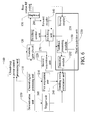
- FIG. 1 is a schematic diagram of a closed-loop power control circuit applying an embodiment of a method according to the present invention.
- the closed-loop power control circuit mainly includes a closed-loop power control processing unit 160, a feedback processing module 150, and a forward coupler 140.
- the gain consistency of a variable gain circuit 120 in an analog circuit of a transmission channel is poor, i.e. different samples have different gains and the gain value of the same sample varies nonlinearly with temperature and frequency
- An input end of the forward coupler 140 is coupled to a forward output end of a duplexer 130.
- the forward coupler 140 is adapted to sample forward power signals and output a sampled forward power signal.
- the feedback processing module 150 processes the sampled forward power signal, and then outputs a sampled forward power signal in a digital domain.
- An input end of the closed-loop power control processing unit 160 is connected to an output end of the feedback processing module 150.
- the closed-loop power control processing unit 160 adjusts a gain value generated by the variable gain circuit 120 according to a digital domain power (i.e. the power at point A in FIG. 1 ) of a forward transmission channel output by a channel digital processing unit 110 and the sampled forward power signal in the digital domain, thereby ensuring that a total output power (i.e. the power at point B in FIG. 1 ) of the base station meets the system configuration requirements.
- a digital domain power i.e. the power at point A in FIG. 1
- a channel digital processing unit 110 i.e. the power at point A in FIG. 1
- the feedback processing module 150 detects that the sampled forward power signal is less than a predetermined value, a gain value of the variable gain circuit 120 is increased, so that the output power of the base station system will reach the predetermined value.
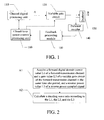
- FIG. 2 is a flow chart of an embodiment of a standing wave detection method according to the present invention.
- step A1 a forward digital domain power value L1 of a forward transmission channel, a gain value L2 of a variable gain circuit of the forward transmission channel, and a reverse power value L3 of a sampled reverse power signal in a same time slot are acquired.
- the forward digital domain power value L1 of a forward transmission channel the gain value L2 of the variable gain circuit 120 of the forward transmission channel, and the reverse power value L3 of a sampled reverse power signal are acquired.
- the sampled reverse power signal is digitized by the feedback processing module 150 in the closed-loop power control circuit, and the reverse power value L3 is then acquired by detecting a sampled reverse power signal in the digital domain, Furthermore, the method for acquiring the reverse power value L3 of the reverse power signal is not thus limited, and other methods may also be used.
- step A2 a standing wave ratio is obtained according to the L1, L2, and L3.
- a forward power value L4 may be obtained according to the acquired forward digital domain power value L1 and gain value L2 of the variable gain circuit 120. Then the standing wave ratio may be obtained according to the forward power value L4 and the reverse power value L3.
- the embodiment of the standing wave detection method in the present invention can acquire a forward power value L4 and a reverse power value L3 in a same time slot by using existing circuits in the base station system when collecting the forward power value and the reverse power value without adding a separate detection circuit, thereby the production costs can be saved.
- the embodiment of the standing wave detection method in the present invention may detect multiple sets of L1, L2, and L3, and may obtain mean values of the multiple L1, L2 and L3 separately. Thus the precision of standing wave detection can be increased.
- the embodiment of the standing wave detection method in the present invention may further include the following step between steps A1 and A2.
- the step of obtaining the standing wave ratio according to the L1, L2, and L3 is triggered. If it is determined that any of the L1, L2, and L3 is invalid, the current standing wave detection process is stopped, and the step of acquiring the forward digital domain power value L1 of the forward transmission channel, the gain value L2 of the variable gain circuit 120 of the forward transmission channel, and the reverse power value L3 of the sampled reverse power signal in a same time slot is performed again.
- the reasonableness determination of the acquired L1, L2, and L3 is added in the embodiment of the standing wave detection method in the present invention, and thus the precision of standing wave detection can be increased.
- FIG. 3 is a schematic diagram of an embodiment of a standing wave detection device according to the present invention.
- the standing wave detection device mainly includes a first acquisition unit 210, a second acquisition unit 220, a third acquisition unit 230, and a standing wave calculation unit 240.
- the first acquisition unit 210 is adapted to acquire a forward digital domain power value L1 of a forward transmission channel.
- the second acquisition unit 220 is adapted to acquire a gain value L2 of a variable gain circuit 120 of the forward transmission channel.
- the third acquisition unit 230 is adapted to acquire a reverse power value L3 of a sampled reverse power signal.
- the standing wave calculation unit 240 is adapted to obtain a standing wave ratio according to the L1, L2, and L3.
- the embodiment of the standing wave detection device in the present invention may further include a determination unit 250 and a trigger unit 260.
- the determination unit 250 is adapted to determine the validity of the L1 acquired by the first acquisition unit 210, the L2 acquired by the second acquisition unit 220, and the L3 acquired by the third acquisition unit 230. Because the L1, L2, and L3 are parameters related to specific base station systems, they have certain reasonable ranges respectively.
- the trigger unit 260 triggers the standing wave calculation unit 240 to obtain the standing wave ratio according to the L1, L2, and L3 if the determination unit 250 determines that the L1, L2, and L3 are all valid.
- the reasonableness determination of the acquired L1, L2, and L3 is added in the embodiment of the standing wave detection device in the present invention, and thus the detection precision of the standing wave detection device can be increased.
- the standing wave calculation unit 240 obtains the standing wave ratio according to mean values of multiple L1, L2 and L3 separately.
- FIG. 4 is a schematic diagram of the third acquisition unit in the embodiment of the standing wave detection device according to the present invention.
- the third acquisition unit 230 may include: a reverse coupler 231, the feedback processing module 150, and a detection module 232.
- the reverse coupler 231 has an input end coupled to a reverse output end of a duplexer and an output end coupled to an input end of the feedback processing module 150.
- the reverse coupler 231 is adapted to sample reverse power signals and output a sampled reverse power signal.
- the feedback processing module 150 is adapted to convert the sampled reverse power signal output by the reverse coupler 231 into a sampled reverse power signal in a digital domain and output the sampled reverse power signal in the digital domain.
- the detection module 232 is adapted to detect the reverse power value L3 of the sampled reverse power signal in the digital domain output by the feedback processing module 150.
- the reverse coupler 231 acquires the sampled reverse power signal, then the feedback processing module 150 converts the sampled reverse power signal into a sampled reverse power signal in the digital domain, and the detection module 232 detects a power value of the sampled reverse power signal in the digital domain that is output by the feedback processing module 150 to obtain the reverse power value L3.
- the prior art requires the use of logarithmic detectors in acquisition of both a forward power value and a reverse power value.
- the embodiment of the present invention uses the feedback processing module 150 and the detection module 232 to acquire the reverse power value L3 without using any logarithmic detector, and the feedback processing module 150 exists in an existing closed-loop power control circuit.
- the embodiment of the present invention further acquires a forward power value according to a power relationship of the closed-loop power control circuit. Therefore, the embodiment of the standing wave detection device in the present invention uses an existing closed-loop circuit for standing wave detection without using a dedicated detection circuit, and thus the cost of the standing wave detection device can be reduced.
- FIG. 5 is a schematic diagram of the feedback processing module in the embodiment of the standing wave detection device according to the present invention.
- Feedback processing module 150 may further include a mixer 151 and an analog-to-digital (A/D) converter 152.
- the mixer 151 is adapted to perform frequency-convert processing to the sampled reverse power signal output by the reverse coupler 231, and then the processed signal is output by the mixer 151.
- the A/D converter 152 is adapted to convert the output signal of the mixer 151 into the sampled reverse power signal in the digital domain, and the output signal of mixer 151 is a frequency-converted sampled reverse power signal.
- the embodiment of the standing wave detection device in the present invention uses the A/D converter having high precision and good stability when detecting the reverse power value, thereby the detection precision and temperature stability of the standing wave detection device can be increased.
- FIG. 6 is a schematic diagram of an embodiment of a base station according to the present invention.
- the embodiment of the base station provided in the present invention mainly includes: the first acquisition unit 210, the second acquisition unit 220 , the third acquisition unit 230, and the standing wave calculation unit 240.
- the first acquisition unit 210 is adapted to acquire the forward digital domain power value L1 of a forward transmission channel.
- the second acquisition unit 220 is adapted to acquire a gain value L2 of a variable gain circuit of the forward transmission channel.
- the third acquisition unit 230 is adapted to acquire the reverse power value L3 of a sampled reverse power signal.
- the standing wave calculation unit 240 is adapted to obtain the standing wave ratio according to the L1, L2, and L3.
- the embodiment of the base station provided in the present invention may further include the determination unit 250 and the trigger unit 260.
- the determination unit 250 is adapted to determine whether the L1, L2, and L3 are valid.
- the trigger unit 260 is adapted to trigger the standing wave calculation unit 240 to obtain the standing wave ratio according to the L1, L2, and L3 if the determination unit 250 determines that the L1, L2, and L3 are all valid.
- the third acquisition unit 230 in the embodiment of the base station in the present invention may include the reverse coupler 231, the feedback processing module 150, and the detection module 232.
- the reverse coupler 231 has an input end coupled to a reverse output end of a duplexer and an output end coupled to an input end of the feedback processing module 150.
- the reverse coupler 231 is adapted to sample reverse power signals and output a sampled reverse power signal.
- the feedback processing module 150 is adapted to convert the sampled reverse power signal output by the reverse coupler 231 into a sampled reverse power signal in a digital domain and output the sampled reverse power signal in the digital domain.
- the detection module 232 is adapted to detect the reverse power value L3 of the sampled reverse power signal in the digital domain output by the feedback processing module 150.
- the embodiment of the base station in the present invention may further include a forward coupler 140, a switching unit 270, a switching control unit 280, and the closed-loop power control processing unit 160.
- the forward coupler 140 has an input end coupled to a forward output end of the duplexer and an output end coupled to the input end of the feedback processing module 150.
- the forward coupler 140 is adapted to sample forward power signals and output a sampled forward power signal.
- the feedback processing module 150 is further adapted to convert the sampled forward power signal output by the forward coupler 140 into a sampled forward power signal in the digital domain and output the sampled forward power signal in the digital domain.
- the switching unit 270 is adapted to switch an input signal of the feedback processing module 150 between the sampled forward power signal and the sampled reverse power signal.
- the switching control unit 280 is adapted to control the switching operation of the switching unit 270.
- the closed-loop power control processing unit 160 has an input end connected to an output end of the feedback processing module 150 and an output end connected to the variable gain circuit of the forward transmission channel.
- the closed-loop power control processing unit 160 is adapted to adjust a gain value of the variable gain circuit 120 of the forward transmission channel according to the input sampled forward power signal after the switching unit 270 switches the input signal of the feedback processing module 150 to the sampled forward power signal.
- the base station may perform time division multiplexing on the closed-loop power control circuit.
- the switching unit 270 switches the input signal of the feedback processing module 150 to the sampled forward power signal, i.e. the input end of the feedback processing module 150 is connected to the output end of the forward coupler 140
- the closed-loop power control circuit is adapted to control an output power of the base station, adjust a gain value of the variable gain circuit 120, and ensure a stable power of a forward transmit power signal of the base station.
- the switching unit 270 switches the input signal of the feedback processing module 150 to the sampled reverse power signal, i.e., the input end of the feedback processing module 150 is connected to the output end of the reverse coupler 231, the closed-loop power control circuit performs standing wave detection. Therefore, the embodiment of the base station in the present invention can realize both the closed-loop power control function and the standing wave detection function.
- the standing wave detection function and the closed-loop power control function are applied in time division multiplexing, so that part of the hardware circuit can be shared, and thus the production cost of the base station can be saved.
- the feedback processing module may further include a mixer 151 and an A/D converter 152.
- the mixer 151 is adapted to perform frequency-convert processing to the sampled reverse power signal output by the reverse coupler 231 when the input signal of the feedback processing module 150 is switched to the sampled reverse power signal.
- the mixer 151 is adapted to perform frequency-convert processing the sampled forward power signal output by the reverse coupler 140 when the input signal of the feedback processing module 150 is switched to the sampled forward power signal. Then the processed signal of the mixer 151 is output by the mixer 151.
- the A/D converter 152 is adapted to convert the sampled reverse power signal frequency-converted and output by the mixer 151 into the sampled reverse power signal in the digital domain, or convert the sampled forward power signal frequency-converted and output by the mixer 151 into the sampled forward power signal in the digital domain.
- the embodiment of the base station in the present invention uses the A/D converter having high precision and good stability when detecting the reverse power value, thereby the detection precision and temperature stability of standing wave detection can be increased.
- the switching unit 270 may be a single pole double throw switch or other components having the input signal selection function.
- the standing wave calculation unit 240 and the closed-loop power control processing unit 160 are applied in time division multiplexing, so that the production cost can also be saved.
- the present invention may be implemented by hardware only or by software and a necessary universal hardware platform. Based on such understandings, the technical solution under the present invention may be embodied in the form of a software product.
- the software product may be stored in a nonvolatile storage medium, which can be a Compact Disk Read-Only Memory (CD-ROM), USB flash drive, or a removable hard drive.
- the software product includes a number of instructions that enable a computer device (personal computer, server, or network device) to execute the methods provided in the embodiments of the present invention.
Landscapes
- Physics & Mathematics (AREA)
- Electromagnetism (AREA)
- Engineering & Computer Science (AREA)
- Computer Networks & Wireless Communication (AREA)
- Signal Processing (AREA)
- Mobile Radio Communication Systems (AREA)
- Transmitters (AREA)
Claims (13)
- Stehwellen-Detektionsverfahren, umfassend:Beschaffen (A1) eines Vorwärts-Digitaldomänen-Leistungswerts L1 eines Vorwärts-Übertragungskanals und eines Verstärkungswerts L2 einer variablen Verstärkungsschaltung des Vorwärts-Übertragungskanals und eines Rückwärts-Leistungswerts L3 eines abgetasteten Rückwärts-Leistungssignals in einem selben Zeitschlitz, wobei das abgetastete Rückwärts-Leistungssignal durch einen Rückwärts-Koppler (231) aus Rückwärts-Leistungssignalen abgetastet wird; undErhalten (A2) eines Stehwellenverhältnisses gemäß L1, L2 und L3;wobei das Erhalten des Stehwellenverhältnisses gemäß L1, L2 und L3 Folgendes umfasst:Erhalten eines Vorwärts-Leistungswerts L4 gemäß L1 und L2 undErhalten des Stehwellenverhältnisses gemäß L4 und L3.
- Stehwellen-Detektionsverfahren nach Anspruch 1, wobei das Beschaffen von L3 Folgendes umfasst:Digitalisieren eines abgetasteten Rückwärts-Leistungssignals durch ein Rückkopplungsverarbeitungsmodul in einer Leistungsregelschaltung mit geschlossener Schleife;Beschaffen von L3 durch Detektieren eines abgetasteten Rückwärts-Leistungssignals in einer Digitaldomäne.
- Stehwellen-Detektionsverfahren nach einem der Ansprüche 1-2, ferner umfassend:Bestimmen, dass L1, L2 und L3 alle gültig sind, bevor das Stehwellenverhältnis erhalten wird.
- Stehwellen-Detektionsverfahren nach einem der Ansprüche 1-3, wobei das Erhalten des Stehwellenverhältnisses Folgendes umfasst:Erhalten von Mittelwerten mehrerer L1, L2 und L3 separat;Erhalten des Stehwellenverhältnisses gemäß den Mittelwerten der mehreren L1, L2 und L3.
- Stehwellen-Detektionsvorrichtung, umfassend:eine erste Beschaffungseinheit (210), die dafür ausgelegt ist, einen Vorwärts-Digitaldomänen-Leistungswert L1 eines Vorwärts-Übertragungskanals zu beschaffen;eine zweite Beschaffungseinheit (220), die dafür ausgelegt ist, einen Verstärkungswert L2 einer variablen Verstärkungsschaltung des Vorwärts-Übertragungskanals zu beschaffen;eine dritte Beschaffungseinheit (230), die dafür ausgelegt ist, einen Rückwärts-Leistungswert L3 eines abgetasteten Rückwärts-Leistungssignals zu beschaffen,wobei das abgetastete Rückwärts-Leistungssignal durch einen Rückwärts-Koppler (231) aus Rückwärts-Leistungssignalen abgetastet wird, undeine Stehwellen-Berechnungseinheit (240), die dafür ausgelegt ist, ein Stehwellenverhältnis gemäß L1, L2 und L3 zu erhalten, wobei das Stehwellenverhältnis gemäß L3 und einem Vorwärts-Leistungswert L4, der auf der Basis von L1 und L2 erhalten wird, erhalten wird, wobei L1, L2 und L3 in einem selben Zeitschlitz beschafft werden.
- Stehwellen-Detektionsvorrichtung nach Anspruch 5, ferner umfassend:eine Bestimmungseinheit (250), die dafür ausgelegt ist, zu bestimmen, ob L1, L2 und L3 gültig sind; undeine Triggereinheit (260), die dafür ausgelegt ist, die Stehwellen-Berechnungseinheit (240) zu trigger, das Stehwellenverhältnis gemäß L1, L2 und L3 zu erhalten, wenn die Bestimmungseinheit bestimmt, dass L1, L2 und L3 alle gültig sind.
- Stehwellen-Detektionsvorrichtung nach Anspruch 5 oder 6, wobei die dritte Beschaffungseinheit Folgendes umfasst:den Rückwärts-Koppler (231), der ein Eingangsende mit einem Rückwärts-Ausgangsende eines Duplexers und ein Ausgangsende mit einem Eingangsende eines Rückkopplungsverarbeitungsmoduls (150) koppelt und dafür ausgelegt ist,Rückwärts-Leistungssignale abzutasten und ein abgetastetes Rückwärts-Leistungssignal auszugeben;das Rückkopplungsverarbeitungsmodul (150), das dafür ausgelegt ist, das von dem Rückwärts-Koppler (231) ausgegebene abgetastete Rückwärts-Leistungssignal in ein abgetastetes Rückwärts-Leistungssignal in einer Digitaldomäne umzusetzen und das abgetastete Rückwärts-Leistungssignal in der Digitaldomäne auszugeben; undein Detektionsmodul (232), das dafür ausgelegt ist, den von dem Rückkopplungsverarbeitungsmodul (150) ausgegebenen Rückwärts-Leistungswert L3 des abgetasteten Rückwärts-Leistungssignals in der Digitaldomäne zu detektieren.
- Stehwellen-Detektionsvorrichtung nach Anspruch 7, wobei das Rückkopplungsverarbeitungsmodul Folgendes umfasst:einen Mischer (151), der dafür ausgelegt ist, Frequenzumsetzungsverarbeitung an dem durch den Rückwärts-Koppler (231) ausgegebenen abgetasteten Rückwärts-Leistungssignal auszuführen und das verarbeitete Signal auszugeben, undeinen Analog-Digital- bzw. A/D-Umsetzer (152), der dafür ausgelegt ist, das durch den Mischer (151) frequenzumgesetzte und ausgegebene abgetastete Rückwärts-Leistungssignal in das abgetastete Rückwärts-Leistungssignal in der Digitaldomäne umzusetzen.
- Stehwellen-Detektionsvorrichtung nach einem der Ansprüche 5-8, wobei die Stehwellen-Berechnungseinheit (240) das Stehwellenverhältnis gemäß Mittelwerten mehrerer L1, L2 und L3 erhält.
- Basisstation, die eine Stehwellen-Detektionsvorrichtung nach einem der Ansprüche 5-9 umfasst.
- Basisstation nach Anspruch 10, ferner umfassend:eine Schalteinheit (270), die dafür ausgelegt ist, ein Eingangssignal des Rückkopplungsverarbeitungsmoduls (150) zwischen dem abgetasteten Vorwärts-Leistungssignal und dem abgetasteten Rückwärts-Leistungssignal umzuschalten;eine Schaltsteuereinheit (280), die dafür ausgelegt ist, die Schaltoperation der Schalteinheit (270) zu steuern.
- Basisstation nach Anspruch 11, ferner umfassend:einen Vorwärts-Koppler (140), der dafür ausgelegt ist, Vorwärts-Leistungssignale abzutasten und ein abgetastetes Vorwärts-Leistungssignal auszugeben, wobei der Vorwärts-Koppler (140) ein mit einem Vorwärts-Ausgangsende des Duplexers (130) gekoppeltes Eingangsende und ein mit dem Eingangsende des Rückkopplungsverarbeitungsmoduls (150) gekoppeltes Ausgangsende aufweist und das Rückkopplungsverarbeitungsmodul (150) ferner dafür ausgelegt ist, das durch den Vorwärts-Koppler (140) ausgegebene abgetastete Vorwärts-Leistungssignal in ein abgetastetes Vorwärts-Leistungssignal in der Digitaldomäne umzusetzen und das abgetastete Vorwärts-Leistungssignal in der Digitaldomäne auszugeben; undeine Leistungsregelungs-Verarbeitungseinheit (160) mit geschlossener Schleife, die dafür ausgelegt ist, einen Verstärkungswert der variablen Verstärkungsschaltung des Vorwärts-Übertragungskanals gemäß dem eingegebenen abgetasteten Vorwärts-Leistungssignal in der Digitaldomäne zu justieren, nachdem die Schalteinheit das Eingangssignal des Rückkopplungsverarbeitungsmoduls (150) auf das abgetastete Vorwärts-Leistungssignal umschaltet.
- Basisstation nach Anspruch 11 oder 12, wobei
der Mischer (151) ferner dafür ausgelegt ist, Frequenzumsetzungsverarbeitung an dem durch den Rückwärts-Koppler (231) ausgegebenen abgetasteten Vorwärts-Leistungssignal auszuführen; und
der A/D-Umsetzer (152) ferner dafür ausgelegt ist, das durch den Mischer frequenzumgesetzte und ausgegebene abgetastete Vorwärts-Leistungssignal in das abgetastete Vorwärts-Leistungssignal in der Digitaldomäne umzusetzen.
Applications Claiming Priority (1)
| Application Number | Priority Date | Filing Date | Title |
|---|---|---|---|
| CN 200910050984 CN101557601B (zh) | 2009-05-07 | 2009-05-07 | 驻波检测方法、驻波检测装置和基站 |
Publications (2)
| Publication Number | Publication Date |
|---|---|
| EP2249494A1 EP2249494A1 (de) | 2010-11-10 |
| EP2249494B1 true EP2249494B1 (de) | 2013-07-31 |
Family
ID=41175490
Family Applications (1)
| Application Number | Title | Priority Date | Filing Date |
|---|---|---|---|
| EP20100161977 Active EP2249494B1 (de) | 2009-05-07 | 2010-05-05 | Stehwellendetektionsverfahren, Stehwellendetektionsvorrichtung und Basisstation |
Country Status (3)
| Country | Link |
|---|---|
| EP (1) | EP2249494B1 (de) |
| CN (1) | CN101557601B (de) |
| ES (1) | ES2431934T3 (de) |
Families Citing this family (20)
| Publication number | Priority date | Publication date | Assignee | Title |
|---|---|---|---|---|
| CN101958756B (zh) | 2010-02-11 | 2013-04-24 | 华为技术有限公司 | 驻波检测方法、驻波检测装置及基站 |
| CN102457334B (zh) * | 2010-10-22 | 2014-12-10 | 中兴通讯股份有限公司 | 全球微波互联接入系统中驻波比的检测方法和装置 |
| CN102571217B (zh) * | 2010-12-09 | 2014-12-10 | 中兴通讯股份有限公司 | 一种射频设备,以及驻波比检测的装置和方法 |
| CN102223189B (zh) * | 2011-03-14 | 2014-04-09 | 京信通信系统(广州)有限公司 | 多频段dpd、增益和驻波检测控制方法 |
| CN102685039B (zh) * | 2011-03-18 | 2015-01-14 | 鼎桥通信技术有限公司 | 一种驻波比检测方法 |
| US20120250527A1 (en) * | 2011-03-28 | 2012-10-04 | International Business Machines Corporation | Determining Connectivity Of A High Speed Link That Includes An AC-Coupling Capacitor |
| US9113367B2 (en) | 2011-04-29 | 2015-08-18 | Optis Cellular Technology, Llc | Method, apparatus and system for determining voltage standing wave ratio in a downlink period of radio communication |
| CN102215074B (zh) * | 2011-06-03 | 2014-01-01 | 京信通信系统(中国)有限公司 | 一种功率和驻波比检测的装置及方法 |
| CN102215075A (zh) * | 2011-06-03 | 2011-10-12 | 大唐移动通信设备有限公司 | 一种对天线进行驻波检测的方法及装置 |
| CN102325339B (zh) * | 2011-07-22 | 2014-08-13 | 京信通信系统(中国)有限公司 | 驻波检测方法、装置及射频拉远单元 |
| CN103178909B (zh) * | 2011-12-26 | 2015-07-29 | 鼎桥通信技术有限公司 | 驻波测量电路的故障检测方法和装置 |
| CN103427915B (zh) * | 2012-05-25 | 2016-08-31 | 南京中兴软件有限责任公司 | 一种射频设备驻波比检测中的去干扰方法和装置 |
| CN106571879A (zh) * | 2015-10-12 | 2017-04-19 | 中兴通讯股份有限公司 | 一种功率检测方法及装置 |
| CN106603165B (zh) * | 2017-01-11 | 2020-06-09 | 普联技术有限公司 | 检测功率信号的方法及系统 |
| CN106877886B (zh) * | 2017-01-19 | 2019-03-15 | 深圳国人通信股份有限公司 | 多系统接入平台电压驻波比检测方法和装置 |
| CN107565918B (zh) * | 2017-08-31 | 2024-05-28 | 成都四威功率电子科技有限公司 | 一种兼容脉冲与连续波模式的过驻波、占空比保护电路及其控制方法 |
| CN112118055B (zh) * | 2019-06-04 | 2022-09-16 | 海能达通信股份有限公司 | 一种驻波检测装置及通信设备 |
| CN110958060A (zh) * | 2019-12-31 | 2020-04-03 | 深圳市大富科技股份有限公司 | 相位补偿结构和驻波检测电路 |
| CN113498097B (zh) * | 2020-04-01 | 2023-04-14 | 成都鼎桥通信技术有限公司 | 一种适用于小基站背负天线场景的驻波告警方法和设备 |
| CN117220617A (zh) * | 2023-10-07 | 2023-12-12 | 苏州莱尔微波技术有限公司 | 带驻波检测的自适应射频功率放大器电路及其控制方法 |
Family Cites Families (5)
| Publication number | Priority date | Publication date | Assignee | Title |
|---|---|---|---|---|
| FI108892B (fi) * | 1996-11-21 | 2002-04-15 | Adc Telecommunications Inc | Järjestely antennin kunnon mittaamiseksi radiopuhelinjärjestelmässä |
| KR100218152B1 (ko) * | 1997-02-06 | 1999-09-01 | 서평원 | 기지국 안테나의 전압정재파비 측정장치 및 그 방법 |
| KR100612142B1 (ko) * | 2004-01-16 | 2006-08-11 | 주식회사 케이티프리텔 | 이동통신 단말을 이용한 공중선계 원격 측정 감시 장치 및그 방법 |
| CN1925348B (zh) * | 2006-10-10 | 2010-04-21 | 华为技术有限公司 | 驻波比检测方法及装置 |
| CN101132240A (zh) * | 2007-09-28 | 2008-02-27 | 摩比天线技术(深圳)有限公司 | 一种驻波检测装置及方法 |
-
2009
- 2009-05-07 CN CN 200910050984 patent/CN101557601B/zh not_active Expired - Fee Related
-
2010
- 2010-05-05 EP EP20100161977 patent/EP2249494B1/de active Active
- 2010-05-05 ES ES10161977T patent/ES2431934T3/es active Active
Also Published As
| Publication number | Publication date |
|---|---|
| EP2249494A1 (de) | 2010-11-10 |
| CN101557601A (zh) | 2009-10-14 |
| ES2431934T3 (es) | 2013-11-28 |
| CN101557601B (zh) | 2013-08-07 |
Similar Documents
| Publication | Publication Date | Title |
|---|---|---|
| EP2249494A1 (de) | Stehwellendetektionsverfahren, Stehwellendetektionsvorrichtung und Basisstation | |
| US11038603B2 (en) | Antenna detection through noise measurement | |
| CN103064070B (zh) | 一种单脉冲雷达系统自检与状态参数的监测结构和方法 | |
| EP2475104A1 (de) | Verfahren und vorrichtung zur erkennung einer fehlfunktion bei einem duplexer | |
| CN109155638B (zh) | 一种收音机天线诊断电路、诊断方法及装置 | |
| EP2469725A1 (de) | Mimo-system und verfahren | |
| CN108513692A (zh) | 一种射频控制系统和控制方法 | |
| CN107872284A (zh) | 无线直放站的自激检测方法及装置 | |
| CN112731315B (zh) | 一种大阵面数字阵雷达快速幅相校准系统及方法 | |
| CN108802711B (zh) | 一种信号接收装置及方法、激光雷达 | |
| CN107863974A (zh) | 一种固态发射机前级网络自动切换控制系统 | |
| EP1758281A1 (de) | Sender-lastimpedanz-fehlerhaft-detektionssystem | |
| CN112350744B (zh) | 天线切换方法、装置、信号收发电路和电子设备 | |
| CN106877886A (zh) | 多系统接入平台电压驻波比检测方法和装置 | |
| CN103327600A (zh) | 一种射频链路增益自动控制装置及方法 | |
| CN101610119A (zh) | 差错检测器、差错检测方法及其控制程序 | |
| CN101282143A (zh) | 一种测量射频发射功率的装置和方法 | |
| CN209673988U (zh) | 一种高中频雷达数字接收机 | |
| US6985514B2 (en) | Automatic gain control circuit and method for direct sequence spread spectrum receiver | |
| WO2012155848A1 (zh) | 一种自动增益控制方法及装置 | |
| CN106896263A (zh) | 一种宽带射频功率测量系统 | |
| KR102753998B1 (ko) | 이득 제어 모드의 선택이 가능한 자동 이득 제어 장치 및 그를 위한 방법 | |
| KR101029598B1 (ko) | 레이더 수신기 | |
| CN106569021B (zh) | 一种用于射频功率反射计的信号调理电路 | |
| KR101895727B1 (ko) | 레이더의 증폭기 제어 방법 및 장치 |
Legal Events
| Date | Code | Title | Description |
|---|---|---|---|
| PUAI | Public reference made under article 153(3) epc to a published international application that has entered the european phase |
Free format text: ORIGINAL CODE: 0009012 |
|
| AK | Designated contracting states |
Kind code of ref document: A1 Designated state(s): AL AT BE BG CH CY CZ DE DK EE ES FI FR GB GR HR HU IE IS IT LI LT LU LV MC MK MT NL NO PL PT RO SE SI SK SM TR |
|
| AX | Request for extension of the european patent |
Extension state: BA ME RS |
|
| 17P | Request for examination filed |
Effective date: 20101223 |
|
| GRAP | Despatch of communication of intention to grant a patent |
Free format text: ORIGINAL CODE: EPIDOSNIGR1 |
|
| GRAS | Grant fee paid |
Free format text: ORIGINAL CODE: EPIDOSNIGR3 |
|
| GRAA | (expected) grant |
Free format text: ORIGINAL CODE: 0009210 |
|
| AK | Designated contracting states |
Kind code of ref document: B1 Designated state(s): AL AT BE BG CH CY CZ DE DK EE ES FI FR GB GR HR HU IE IS IT LI LT LU LV MC MK MT NL NO PL PT RO SE SI SK SM TR |
|
| REG | Reference to a national code |
Ref country code: GB Ref legal event code: FG4D Ref country code: CH Ref legal event code: EP |
|
| REG | Reference to a national code |
Ref country code: AT Ref legal event code: REF Ref document number: 625162 Country of ref document: AT Kind code of ref document: T Effective date: 20130815 |
|
| REG | Reference to a national code |
Ref country code: IE Ref legal event code: FG4D |
|
| REG | Reference to a national code |
Ref country code: DE Ref legal event code: R096 Ref document number: 602010008974 Country of ref document: DE Effective date: 20130926 |
|
| REG | Reference to a national code |
Ref country code: SE Ref legal event code: TRGR |
|
| REG | Reference to a national code |
Ref country code: NL Ref legal event code: T3 |
|
| REG | Reference to a national code |
Ref country code: LT Ref legal event code: MG4D |
|
| PG25 | Lapsed in a contracting state [announced via postgrant information from national office to epo] |
Ref country code: PT Free format text: LAPSE BECAUSE OF FAILURE TO SUBMIT A TRANSLATION OF THE DESCRIPTION OR TO PAY THE FEE WITHIN THE PRESCRIBED TIME-LIMIT Effective date: 20131202 Ref country code: IS Free format text: LAPSE BECAUSE OF FAILURE TO SUBMIT A TRANSLATION OF THE DESCRIPTION OR TO PAY THE FEE WITHIN THE PRESCRIBED TIME-LIMIT Effective date: 20131130 Ref country code: CY Free format text: LAPSE BECAUSE OF FAILURE TO SUBMIT A TRANSLATION OF THE DESCRIPTION OR TO PAY THE FEE WITHIN THE PRESCRIBED TIME-LIMIT Effective date: 20130911 Ref country code: BE Free format text: LAPSE BECAUSE OF FAILURE TO SUBMIT A TRANSLATION OF THE DESCRIPTION OR TO PAY THE FEE WITHIN THE PRESCRIBED TIME-LIMIT Effective date: 20130731 Ref country code: NO Free format text: LAPSE BECAUSE OF FAILURE TO SUBMIT A TRANSLATION OF THE DESCRIPTION OR TO PAY THE FEE WITHIN THE PRESCRIBED TIME-LIMIT Effective date: 20131031 Ref country code: LT Free format text: LAPSE BECAUSE OF FAILURE TO SUBMIT A TRANSLATION OF THE DESCRIPTION OR TO PAY THE FEE WITHIN THE PRESCRIBED TIME-LIMIT Effective date: 20130731 Ref country code: HR Free format text: LAPSE BECAUSE OF FAILURE TO SUBMIT A TRANSLATION OF THE DESCRIPTION OR TO PAY THE FEE WITHIN THE PRESCRIBED TIME-LIMIT Effective date: 20130731 |
|
| PG25 | Lapsed in a contracting state [announced via postgrant information from national office to epo] |
Ref country code: PL Free format text: LAPSE BECAUSE OF FAILURE TO SUBMIT A TRANSLATION OF THE DESCRIPTION OR TO PAY THE FEE WITHIN THE PRESCRIBED TIME-LIMIT Effective date: 20130731 Ref country code: GR Free format text: LAPSE BECAUSE OF FAILURE TO SUBMIT A TRANSLATION OF THE DESCRIPTION OR TO PAY THE FEE WITHIN THE PRESCRIBED TIME-LIMIT Effective date: 20131101 Ref country code: LV Free format text: LAPSE BECAUSE OF FAILURE TO SUBMIT A TRANSLATION OF THE DESCRIPTION OR TO PAY THE FEE WITHIN THE PRESCRIBED TIME-LIMIT Effective date: 20130731 Ref country code: SI Free format text: LAPSE BECAUSE OF FAILURE TO SUBMIT A TRANSLATION OF THE DESCRIPTION OR TO PAY THE FEE WITHIN THE PRESCRIBED TIME-LIMIT Effective date: 20130731 Ref country code: FI Free format text: LAPSE BECAUSE OF FAILURE TO SUBMIT A TRANSLATION OF THE DESCRIPTION OR TO PAY THE FEE WITHIN THE PRESCRIBED TIME-LIMIT Effective date: 20130731 |
|
| PG25 | Lapsed in a contracting state [announced via postgrant information from national office to epo] |
Ref country code: CY Free format text: LAPSE BECAUSE OF FAILURE TO SUBMIT A TRANSLATION OF THE DESCRIPTION OR TO PAY THE FEE WITHIN THE PRESCRIBED TIME-LIMIT Effective date: 20130731 |
|
| PG25 | Lapsed in a contracting state [announced via postgrant information from national office to epo] |
Ref country code: DK Free format text: LAPSE BECAUSE OF FAILURE TO SUBMIT A TRANSLATION OF THE DESCRIPTION OR TO PAY THE FEE WITHIN THE PRESCRIBED TIME-LIMIT Effective date: 20130731 Ref country code: EE Free format text: LAPSE BECAUSE OF FAILURE TO SUBMIT A TRANSLATION OF THE DESCRIPTION OR TO PAY THE FEE WITHIN THE PRESCRIBED TIME-LIMIT Effective date: 20130731 Ref country code: SK Free format text: LAPSE BECAUSE OF FAILURE TO SUBMIT A TRANSLATION OF THE DESCRIPTION OR TO PAY THE FEE WITHIN THE PRESCRIBED TIME-LIMIT Effective date: 20130731 Ref country code: RO Free format text: LAPSE BECAUSE OF FAILURE TO SUBMIT A TRANSLATION OF THE DESCRIPTION OR TO PAY THE FEE WITHIN THE PRESCRIBED TIME-LIMIT Effective date: 20130731 Ref country code: CZ Free format text: LAPSE BECAUSE OF FAILURE TO SUBMIT A TRANSLATION OF THE DESCRIPTION OR TO PAY THE FEE WITHIN THE PRESCRIBED TIME-LIMIT Effective date: 20130731 |
|
| PG25 | Lapsed in a contracting state [announced via postgrant information from national office to epo] |
Ref country code: IT Free format text: LAPSE BECAUSE OF FAILURE TO SUBMIT A TRANSLATION OF THE DESCRIPTION OR TO PAY THE FEE WITHIN THE PRESCRIBED TIME-LIMIT Effective date: 20130731 |
|
| PLBE | No opposition filed within time limit |
Free format text: ORIGINAL CODE: 0009261 |
|
| STAA | Information on the status of an ep patent application or granted ep patent |
Free format text: STATUS: NO OPPOSITION FILED WITHIN TIME LIMIT |
|
| 26N | No opposition filed |
Effective date: 20140502 |
|
| REG | Reference to a national code |
Ref country code: DE Ref legal event code: R097 Ref document number: 602010008974 Country of ref document: DE Effective date: 20140502 |
|
| PG25 | Lapsed in a contracting state [announced via postgrant information from national office to epo] |
Ref country code: LU Free format text: LAPSE BECAUSE OF FAILURE TO SUBMIT A TRANSLATION OF THE DESCRIPTION OR TO PAY THE FEE WITHIN THE PRESCRIBED TIME-LIMIT Effective date: 20140505 |
|
| PG25 | Lapsed in a contracting state [announced via postgrant information from national office to epo] |
Ref country code: MC Free format text: LAPSE BECAUSE OF FAILURE TO SUBMIT A TRANSLATION OF THE DESCRIPTION OR TO PAY THE FEE WITHIN THE PRESCRIBED TIME-LIMIT Effective date: 20130731 |
|
| REG | Reference to a national code |
Ref country code: IE Ref legal event code: MM4A |
|
| PG25 | Lapsed in a contracting state [announced via postgrant information from national office to epo] |
Ref country code: IE Free format text: LAPSE BECAUSE OF NON-PAYMENT OF DUE FEES Effective date: 20140505 |
|
| PG25 | Lapsed in a contracting state [announced via postgrant information from national office to epo] |
Ref country code: MT Free format text: LAPSE BECAUSE OF FAILURE TO SUBMIT A TRANSLATION OF THE DESCRIPTION OR TO PAY THE FEE WITHIN THE PRESCRIBED TIME-LIMIT Effective date: 20130731 |
|
| REG | Reference to a national code |
Ref country code: FR Ref legal event code: PLFP Year of fee payment: 7 |
|
| PG25 | Lapsed in a contracting state [announced via postgrant information from national office to epo] |
Ref country code: SM Free format text: LAPSE BECAUSE OF FAILURE TO SUBMIT A TRANSLATION OF THE DESCRIPTION OR TO PAY THE FEE WITHIN THE PRESCRIBED TIME-LIMIT Effective date: 20130731 |
|
| PG25 | Lapsed in a contracting state [announced via postgrant information from national office to epo] |
Ref country code: BG Free format text: LAPSE BECAUSE OF FAILURE TO SUBMIT A TRANSLATION OF THE DESCRIPTION OR TO PAY THE FEE WITHIN THE PRESCRIBED TIME-LIMIT Effective date: 20130731 |
|
| PG25 | Lapsed in a contracting state [announced via postgrant information from national office to epo] |
Ref country code: TR Free format text: LAPSE BECAUSE OF FAILURE TO SUBMIT A TRANSLATION OF THE DESCRIPTION OR TO PAY THE FEE WITHIN THE PRESCRIBED TIME-LIMIT Effective date: 20130731 Ref country code: HU Free format text: LAPSE BECAUSE OF FAILURE TO SUBMIT A TRANSLATION OF THE DESCRIPTION OR TO PAY THE FEE WITHIN THE PRESCRIBED TIME-LIMIT; INVALID AB INITIO Effective date: 20100505 |
|
| REG | Reference to a national code |
Ref country code: FR Ref legal event code: PLFP Year of fee payment: 8 |
|
| REG | Reference to a national code |
Ref country code: FR Ref legal event code: PLFP Year of fee payment: 9 |
|
| PG25 | Lapsed in a contracting state [announced via postgrant information from national office to epo] |
Ref country code: MK Free format text: LAPSE BECAUSE OF FAILURE TO SUBMIT A TRANSLATION OF THE DESCRIPTION OR TO PAY THE FEE WITHIN THE PRESCRIBED TIME-LIMIT Effective date: 20130731 |
|
| PG25 | Lapsed in a contracting state [announced via postgrant information from national office to epo] |
Ref country code: AL Free format text: LAPSE BECAUSE OF FAILURE TO SUBMIT A TRANSLATION OF THE DESCRIPTION OR TO PAY THE FEE WITHIN THE PRESCRIBED TIME-LIMIT Effective date: 20130731 |
|
| REG | Reference to a national code |
Ref country code: FR Ref legal event code: PLFP Year of fee payment: 14 |
|
| PGFP | Annual fee paid to national office [announced via postgrant information from national office to epo] |
Ref country code: NL Payment date: 20250409 Year of fee payment: 16 |
|
| PGFP | Annual fee paid to national office [announced via postgrant information from national office to epo] |
Ref country code: DE Payment date: 20250402 Year of fee payment: 16 |
|
| PGFP | Annual fee paid to national office [announced via postgrant information from national office to epo] |
Ref country code: GB Payment date: 20250401 Year of fee payment: 16 Ref country code: ES Payment date: 20250606 Year of fee payment: 16 |
|
| PGFP | Annual fee paid to national office [announced via postgrant information from national office to epo] |
Ref country code: FR Payment date: 20250401 Year of fee payment: 16 |
|
| PGFP | Annual fee paid to national office [announced via postgrant information from national office to epo] |
Ref country code: CH Payment date: 20250601 Year of fee payment: 16 |
|
| PGFP | Annual fee paid to national office [announced via postgrant information from national office to epo] |
Ref country code: AT Payment date: 20250425 Year of fee payment: 16 |
|
| PGFP | Annual fee paid to national office [announced via postgrant information from national office to epo] |
Ref country code: SE Payment date: 20250411 Year of fee payment: 16 |