EP2249424B1 - Solid oxide fuel cell device and system, method of using and method of making - Google Patents
Solid oxide fuel cell device and system, method of using and method of making Download PDFInfo
- Publication number
- EP2249424B1 EP2249424B1 EP10004486.6A EP10004486A EP2249424B1 EP 2249424 B1 EP2249424 B1 EP 2249424B1 EP 10004486 A EP10004486 A EP 10004486A EP 2249424 B1 EP2249424 B1 EP 2249424B1
- Authority
- EP
- European Patent Office
- Prior art keywords
- fuel
- zone
- passages
- air
- anode
- Prior art date
- Legal status (The legal status is an assumption and is not a legal conclusion. Google has not performed a legal analysis and makes no representation as to the accuracy of the status listed.)
- Not-in-force
Links
Images


Classifications
-
- H—ELECTRICITY
- H01—ELECTRIC ELEMENTS
- H01M—PROCESSES OR MEANS, e.g. BATTERIES, FOR THE DIRECT CONVERSION OF CHEMICAL ENERGY INTO ELECTRICAL ENERGY
- H01M8/00—Fuel cells; Manufacture thereof
- H01M8/24—Grouping of fuel cells, e.g. stacking of fuel cells
- H01M8/241—Grouping of fuel cells, e.g. stacking of fuel cells with solid or matrix-supported electrolytes
- H01M8/2425—High-temperature cells with solid electrolytes
- H01M8/2432—Grouping of unit cells of planar configuration
-
- H—ELECTRICITY
- H01—ELECTRIC ELEMENTS
- H01M—PROCESSES OR MEANS, e.g. BATTERIES, FOR THE DIRECT CONVERSION OF CHEMICAL ENERGY INTO ELECTRICAL ENERGY
- H01M8/00—Fuel cells; Manufacture thereof
- H01M8/002—Shape, form of a fuel cell
- H01M8/006—Flat
-
- H—ELECTRICITY
- H01—ELECTRIC ELEMENTS
- H01M—PROCESSES OR MEANS, e.g. BATTERIES, FOR THE DIRECT CONVERSION OF CHEMICAL ENERGY INTO ELECTRICAL ENERGY
- H01M8/00—Fuel cells; Manufacture thereof
- H01M8/04—Auxiliary arrangements, e.g. for control of pressure or for circulation of fluids
-
- H—ELECTRICITY
- H01—ELECTRIC ELEMENTS
- H01M—PROCESSES OR MEANS, e.g. BATTERIES, FOR THE DIRECT CONVERSION OF CHEMICAL ENERGY INTO ELECTRICAL ENERGY
- H01M8/00—Fuel cells; Manufacture thereof
- H01M8/02—Details
- H01M8/0202—Collectors; Separators, e.g. bipolar separators; Interconnectors
- H01M8/0204—Non-porous and characterised by the material
- H01M8/0206—Metals or alloys
-
- H—ELECTRICITY
- H01—ELECTRIC ELEMENTS
- H01M—PROCESSES OR MEANS, e.g. BATTERIES, FOR THE DIRECT CONVERSION OF CHEMICAL ENERGY INTO ELECTRICAL ENERGY
- H01M8/00—Fuel cells; Manufacture thereof
- H01M8/02—Details
- H01M8/0202—Collectors; Separators, e.g. bipolar separators; Interconnectors
- H01M8/0247—Collectors; Separators, e.g. bipolar separators; Interconnectors characterised by the form
- H01M8/0252—Collectors; Separators, e.g. bipolar separators; Interconnectors characterised by the form tubular
-
- H—ELECTRICITY
- H01—ELECTRIC ELEMENTS
- H01M—PROCESSES OR MEANS, e.g. BATTERIES, FOR THE DIRECT CONVERSION OF CHEMICAL ENERGY INTO ELECTRICAL ENERGY
- H01M8/00—Fuel cells; Manufacture thereof
- H01M8/02—Details
- H01M8/0202—Collectors; Separators, e.g. bipolar separators; Interconnectors
- H01M8/0247—Collectors; Separators, e.g. bipolar separators; Interconnectors characterised by the form
- H01M8/0256—Vias, i.e. connectors passing through the separator material
-
- H—ELECTRICITY
- H01—ELECTRIC ELEMENTS
- H01M—PROCESSES OR MEANS, e.g. BATTERIES, FOR THE DIRECT CONVERSION OF CHEMICAL ENERGY INTO ELECTRICAL ENERGY
- H01M8/00—Fuel cells; Manufacture thereof
- H01M8/02—Details
- H01M8/0202—Collectors; Separators, e.g. bipolar separators; Interconnectors
- H01M8/0258—Collectors; Separators, e.g. bipolar separators; Interconnectors characterised by the configuration of channels, e.g. by the flow field of the reactant or coolant
- H01M8/0263—Collectors; Separators, e.g. bipolar separators; Interconnectors characterised by the configuration of channels, e.g. by the flow field of the reactant or coolant having meandering or serpentine paths
-
- H—ELECTRICITY
- H01—ELECTRIC ELEMENTS
- H01M—PROCESSES OR MEANS, e.g. BATTERIES, FOR THE DIRECT CONVERSION OF CHEMICAL ENERGY INTO ELECTRICAL ENERGY
- H01M8/00—Fuel cells; Manufacture thereof
- H01M8/02—Details
- H01M8/0202—Collectors; Separators, e.g. bipolar separators; Interconnectors
- H01M8/0258—Collectors; Separators, e.g. bipolar separators; Interconnectors characterised by the configuration of channels, e.g. by the flow field of the reactant or coolant
- H01M8/0265—Collectors; Separators, e.g. bipolar separators; Interconnectors characterised by the configuration of channels, e.g. by the flow field of the reactant or coolant the reactant or coolant channels having varying cross sections
-
- H—ELECTRICITY
- H01—ELECTRIC ELEMENTS
- H01M—PROCESSES OR MEANS, e.g. BATTERIES, FOR THE DIRECT CONVERSION OF CHEMICAL ENERGY INTO ELECTRICAL ENERGY
- H01M8/00—Fuel cells; Manufacture thereof
- H01M8/02—Details
- H01M8/0202—Collectors; Separators, e.g. bipolar separators; Interconnectors
- H01M8/0267—Collectors; Separators, e.g. bipolar separators; Interconnectors having heating or cooling means, e.g. heaters or coolant flow channels
-
- H—ELECTRICITY
- H01—ELECTRIC ELEMENTS
- H01M—PROCESSES OR MEANS, e.g. BATTERIES, FOR THE DIRECT CONVERSION OF CHEMICAL ENERGY INTO ELECTRICAL ENERGY
- H01M8/00—Fuel cells; Manufacture thereof
- H01M8/04—Auxiliary arrangements, e.g. for control of pressure or for circulation of fluids
- H01M8/04007—Auxiliary arrangements, e.g. for control of pressure or for circulation of fluids related to heat exchange
- H01M8/04067—Heat exchange or temperature measuring elements, thermal insulation, e.g. heat pipes, heat pumps, fins
- H01M8/04074—Heat exchange unit structures specially adapted for fuel cell
-
- H—ELECTRICITY
- H01—ELECTRIC ELEMENTS
- H01M—PROCESSES OR MEANS, e.g. BATTERIES, FOR THE DIRECT CONVERSION OF CHEMICAL ENERGY INTO ELECTRICAL ENERGY
- H01M8/00—Fuel cells; Manufacture thereof
- H01M8/04—Auxiliary arrangements, e.g. for control of pressure or for circulation of fluids
- H01M8/04082—Arrangements for control of reactant parameters, e.g. pressure or concentration
- H01M8/04089—Arrangements for control of reactant parameters, e.g. pressure or concentration of gaseous reactants
-
- H—ELECTRICITY
- H01—ELECTRIC ELEMENTS
- H01M—PROCESSES OR MEANS, e.g. BATTERIES, FOR THE DIRECT CONVERSION OF CHEMICAL ENERGY INTO ELECTRICAL ENERGY
- H01M8/00—Fuel cells; Manufacture thereof
- H01M8/06—Combination of fuel cells with means for production of reactants or for treatment of residues
-
- H—ELECTRICITY
- H01—ELECTRIC ELEMENTS
- H01M—PROCESSES OR MEANS, e.g. BATTERIES, FOR THE DIRECT CONVERSION OF CHEMICAL ENERGY INTO ELECTRICAL ENERGY
- H01M8/00—Fuel cells; Manufacture thereof
- H01M8/10—Fuel cells with solid electrolytes
-
- H—ELECTRICITY
- H01—ELECTRIC ELEMENTS
- H01M—PROCESSES OR MEANS, e.g. BATTERIES, FOR THE DIRECT CONVERSION OF CHEMICAL ENERGY INTO ELECTRICAL ENERGY
- H01M8/00—Fuel cells; Manufacture thereof
- H01M8/10—Fuel cells with solid electrolytes
- H01M8/12—Fuel cells with solid electrolytes operating at high temperature, e.g. with stabilised ZrO2 electrolyte
- H01M8/1213—Fuel cells with solid electrolytes operating at high temperature, e.g. with stabilised ZrO2 electrolyte characterised by the electrode/electrolyte combination or the supporting material
- H01M8/1226—Fuel cells with solid electrolytes operating at high temperature, e.g. with stabilised ZrO2 electrolyte characterised by the electrode/electrolyte combination or the supporting material characterised by the supporting layer
-
- H—ELECTRICITY
- H01—ELECTRIC ELEMENTS
- H01M—PROCESSES OR MEANS, e.g. BATTERIES, FOR THE DIRECT CONVERSION OF CHEMICAL ENERGY INTO ELECTRICAL ENERGY
- H01M8/00—Fuel cells; Manufacture thereof
- H01M8/10—Fuel cells with solid electrolytes
- H01M8/12—Fuel cells with solid electrolytes operating at high temperature, e.g. with stabilised ZrO2 electrolyte
- H01M8/124—Fuel cells with solid electrolytes operating at high temperature, e.g. with stabilised ZrO2 electrolyte characterised by the process of manufacturing or by the material of the electrolyte
- H01M8/1246—Fuel cells with solid electrolytes operating at high temperature, e.g. with stabilised ZrO2 electrolyte characterised by the process of manufacturing or by the material of the electrolyte the electrolyte consisting of oxides
-
- H—ELECTRICITY
- H01—ELECTRIC ELEMENTS
- H01M—PROCESSES OR MEANS, e.g. BATTERIES, FOR THE DIRECT CONVERSION OF CHEMICAL ENERGY INTO ELECTRICAL ENERGY
- H01M8/00—Fuel cells; Manufacture thereof
- H01M8/10—Fuel cells with solid electrolytes
- H01M8/12—Fuel cells with solid electrolytes operating at high temperature, e.g. with stabilised ZrO2 electrolyte
- H01M8/1286—Fuel cells applied on a support, e.g. miniature fuel cells deposited on silica supports
-
- H—ELECTRICITY
- H01—ELECTRIC ELEMENTS
- H01M—PROCESSES OR MEANS, e.g. BATTERIES, FOR THE DIRECT CONVERSION OF CHEMICAL ENERGY INTO ELECTRICAL ENERGY
- H01M8/00—Fuel cells; Manufacture thereof
- H01M8/24—Grouping of fuel cells, e.g. stacking of fuel cells
- H01M8/241—Grouping of fuel cells, e.g. stacking of fuel cells with solid or matrix-supported electrolytes
- H01M8/2425—High-temperature cells with solid electrolytes
- H01M8/243—Grouping of unit cells of tubular or cylindrical configuration
-
- H—ELECTRICITY
- H01—ELECTRIC ELEMENTS
- H01M—PROCESSES OR MEANS, e.g. BATTERIES, FOR THE DIRECT CONVERSION OF CHEMICAL ENERGY INTO ELECTRICAL ENERGY
- H01M8/00—Fuel cells; Manufacture thereof
- H01M8/24—Grouping of fuel cells, e.g. stacking of fuel cells
- H01M8/241—Grouping of fuel cells, e.g. stacking of fuel cells with solid or matrix-supported electrolytes
- H01M8/2425—High-temperature cells with solid electrolytes
- H01M8/2435—High-temperature cells with solid electrolytes with monolithic core structure, e.g. honeycombs
-
- H—ELECTRICITY
- H01—ELECTRIC ELEMENTS
- H01M—PROCESSES OR MEANS, e.g. BATTERIES, FOR THE DIRECT CONVERSION OF CHEMICAL ENERGY INTO ELECTRICAL ENERGY
- H01M8/00—Fuel cells; Manufacture thereof
- H01M8/24—Grouping of fuel cells, e.g. stacking of fuel cells
- H01M8/2465—Details of groupings of fuel cells
- H01M8/2484—Details of groupings of fuel cells characterised by external manifolds
-
- H—ELECTRICITY
- H01—ELECTRIC ELEMENTS
- H01M—PROCESSES OR MEANS, e.g. BATTERIES, FOR THE DIRECT CONVERSION OF CHEMICAL ENERGY INTO ELECTRICAL ENERGY
- H01M8/00—Fuel cells; Manufacture thereof
- H01M8/10—Fuel cells with solid electrolytes
- H01M8/12—Fuel cells with solid electrolytes operating at high temperature, e.g. with stabilised ZrO2 electrolyte
- H01M2008/1293—Fuel cells with solid oxide electrolytes
-
- H—ELECTRICITY
- H01—ELECTRIC ELEMENTS
- H01M—PROCESSES OR MEANS, e.g. BATTERIES, FOR THE DIRECT CONVERSION OF CHEMICAL ENERGY INTO ELECTRICAL ENERGY
- H01M4/00—Electrodes
- H01M4/86—Inert electrodes with catalytic activity, e.g. for fuel cells
- H01M4/88—Processes of manufacture
- H01M4/8817—Treatment of supports before application of the catalytic active composition
-
- H—ELECTRICITY
- H01—ELECTRIC ELEMENTS
- H01M—PROCESSES OR MEANS, e.g. BATTERIES, FOR THE DIRECT CONVERSION OF CHEMICAL ENERGY INTO ELECTRICAL ENERGY
- H01M4/00—Electrodes
- H01M4/86—Inert electrodes with catalytic activity, e.g. for fuel cells
- H01M4/88—Processes of manufacture
- H01M4/8825—Methods for deposition of the catalytic active composition
- H01M4/8828—Coating with slurry or ink
-
- H—ELECTRICITY
- H01—ELECTRIC ELEMENTS
- H01M—PROCESSES OR MEANS, e.g. BATTERIES, FOR THE DIRECT CONVERSION OF CHEMICAL ENERGY INTO ELECTRICAL ENERGY
- H01M4/00—Electrodes
- H01M4/86—Inert electrodes with catalytic activity, e.g. for fuel cells
- H01M4/88—Processes of manufacture
- H01M4/8825—Methods for deposition of the catalytic active composition
- H01M4/8842—Coating using a catalyst salt precursor in solution followed by evaporation and reduction of the precursor
-
- H—ELECTRICITY
- H01—ELECTRIC ELEMENTS
- H01M—PROCESSES OR MEANS, e.g. BATTERIES, FOR THE DIRECT CONVERSION OF CHEMICAL ENERGY INTO ELECTRICAL ENERGY
- H01M8/00—Fuel cells; Manufacture thereof
- H01M8/02—Details
- H01M8/0202—Collectors; Separators, e.g. bipolar separators; Interconnectors
- H01M8/0204—Non-porous and characterised by the material
- H01M8/0215—Glass; Ceramic materials
-
- H—ELECTRICITY
- H01—ELECTRIC ELEMENTS
- H01M—PROCESSES OR MEANS, e.g. BATTERIES, FOR THE DIRECT CONVERSION OF CHEMICAL ENERGY INTO ELECTRICAL ENERGY
- H01M8/00—Fuel cells; Manufacture thereof
- H01M8/04—Auxiliary arrangements, e.g. for control of pressure or for circulation of fluids
- H01M8/04082—Arrangements for control of reactant parameters, e.g. pressure or concentration
- H01M8/04201—Reactant storage and supply, e.g. means for feeding, pipes
-
- Y—GENERAL TAGGING OF NEW TECHNOLOGICAL DEVELOPMENTS; GENERAL TAGGING OF CROSS-SECTIONAL TECHNOLOGIES SPANNING OVER SEVERAL SECTIONS OF THE IPC; TECHNICAL SUBJECTS COVERED BY FORMER USPC CROSS-REFERENCE ART COLLECTIONS [XRACs] AND DIGESTS
- Y02—TECHNOLOGIES OR APPLICATIONS FOR MITIGATION OR ADAPTATION AGAINST CLIMATE CHANGE
- Y02E—REDUCTION OF GREENHOUSE GAS [GHG] EMISSIONS, RELATED TO ENERGY GENERATION, TRANSMISSION OR DISTRIBUTION
- Y02E60/00—Enabling technologies; Technologies with a potential or indirect contribution to GHG emissions mitigation
- Y02E60/30—Hydrogen technology
- Y02E60/50—Fuel cells
-
- Y—GENERAL TAGGING OF NEW TECHNOLOGICAL DEVELOPMENTS; GENERAL TAGGING OF CROSS-SECTIONAL TECHNOLOGIES SPANNING OVER SEVERAL SECTIONS OF THE IPC; TECHNICAL SUBJECTS COVERED BY FORMER USPC CROSS-REFERENCE ART COLLECTIONS [XRACs] AND DIGESTS
- Y02—TECHNOLOGIES OR APPLICATIONS FOR MITIGATION OR ADAPTATION AGAINST CLIMATE CHANGE
- Y02P—CLIMATE CHANGE MITIGATION TECHNOLOGIES IN THE PRODUCTION OR PROCESSING OF GOODS
- Y02P70/00—Climate change mitigation technologies in the production process for final industrial or consumer products
- Y02P70/50—Manufacturing or production processes characterised by the final manufactured product
Definitions
- This invention relates to solid oxide fuel cell devices and systems, and methods of manufacturing the devices, and more particularly, to a solid oxide fuel cell device in the form of a multi-layer monolithic SOFC Stick TM .
- Ceramic tubes have found a use in the manufacture of Solid Oxide Fuel Cells (SOFCs).
- SOFCs Solid Oxide Fuel Cells
- the barrier layer (the "electrolyte") between the fuel and the air is a ceramic layer, which allows oxygen atoms to migrate through the layer to complete a chemical reaction. Because ceramic is a poor conductor of oxygen atoms at room temperature, the fuel cell is operated at 700°C to 1000°C, and the ceramic layer is made as thin as possible,
- SOFCs makes use of flat plates of zirconia stacked together with other anodes and cathodes, to achieve the fuel cell structure. Compared to the tall, narrow devices envisioned by Westinghouse, these flat plate structures can be cube shaped, 6 to 8 inches on an edge, with a clamping mechanism to hold the entire stack together.
- a still newer method envisions using larger quantities of small diameter tubes having very thin walls.
- the use of thin walled ceramic is important in SOFCs because the transfer rate of oxygen ions is limited by distance and temperature. If a thinner layer of zirconia is used, the final device can be operated at a lower temperature while maintaining the same efficiency.
- Literature describes the need to make ceramic tubes at 150 ⁇ m or less wall thickness.
- the tubular SOFC approach is better than the competing "stack" type (made from large, flat ceramic plates) because the tube is essentially one-dimensional.
- the tube can get hot in the middle, for example, and expand but not crack.
- a tube furnace can heat a 36" (91.44 cm) long alumina tube, 4" (10.16 cm) in diameter, and it will become red hot in the center, and cold enough to touch at the ends. Because the tube is heated evenly in the center section, that center section expands, making the tube become longer, but it does not crack.
- a ceramic plate heated in the center only would quickly break into pieces because the center expands while the outside remains the same size.
- the key property of the tube is that it is uniaxial, or one-dimensional.
- a second key challenge is to make contact to the SOFC.
- the SOFC ideally operates at high temperature (typically 700-1000°C), yet it also needs to be connected to the outside world for air and fuel, and also to make electrical connection. Ideally, one would like to connect at room temperature. Connecting at high temperature is problematic because organic material cannot be used, so one must use glass seals or mechanical seals. These are unreliable, in part, because of expansion problems. They can also be expensive.
- An SOFC tube is also limited in its scalability. To achieve greater kV output, more tubes must be added. Each tube is a single electrolyte layer, such that increases are bulky. The solid electrolyte tube technology is further limited in terms of achievable electrolyte thinness. A thinner electrolyte is more efficient. Electrolyte thickness of 2 ⁇ m or even 1 ⁇ m would be optimal for high power, but is very difficult to achieve in solid electrolyte tubes. It is note that a single fuel cell area produces about 0.5 to 1 volt (this is inherent due to the driving force of the chemical reaction, in the same way that a battery gives off 1.2 volts), but the current, and therefore the power, depend on several factors. Higher current will result from factors that make more oxygen ions migrate across the electrolyte in a given time. These factors are higher temperature, thinner electrolyte, and larger area.
- JP 2000164239 discloses an electrochemical cell unit of a honeycomb type having gas passages formed almost in parallel to the sidewall of the body.
- One gas is introduced through a gas introducing hole formed in the main face of the body and the other gas is introduced through a gas introducing hole formed in a side wall of the body.
- the present invention provides a solid oxide fuel cell device comprising an elongate substrate having an exterior surface, an interior structure and a length that is the greatest dimension whereby the elongate substrate exhibits thermal expansion along a dominant axis that is coextensive with the length, an active reaction zone along a first portion of the length configured to be exposed to a heat source to heat the active reaction zone to an operating reaction temperature, a plurality of fuel passages each having an associated anode in the active reaction zone, a plurality of oxidizer passages each having an associated cathode in the active reaction zone positioned in opposing relation to a respective one of the associated anodes, and an electrolyte disposed between each of the opposing anodes and cathodes in the active reaction zone, the anodes and cathodes each having an electrical pathway extending from within the interior structure to the exterior surface, wherein the interior structure is a ceramic support structure, the electrolyte in the active reaction zone forming part of the ceramic support structure, and the substrate has at least one in
- the invention further provides a fuel cell system incorporating a plurality of the fuel devices, each device positioned with the first portion in a hot zone chamber and the at least one cold zone extending outside the hot zone chamber.
- a heat source is coupled to the hot zone chamber and adapted to heat the reaction zones of the devices to the operating reaction temperature within the hot zone chamber.
- the system further includes a fuel supply coupled outside the hot zone chamber to the at least one cold zones in fluid communication with the fuel passages for supplying a fuel flow into the fuel passages.
- the method includes providing an elongate monolithic sintered ceramic substrate that has a length that is the greatest dimension whereby the elongate substrate exhibits expansion along only one dominant axis that is coextensive with the length, and the elongate substrate includes a plurality of first passages and a plurality of second passages positioned in opposing relation to a respective one of the plurality of first passages.
- the first passages are then filled with a fluid anode material comprising anode particles and a first liquid, and then the first liquid is removed to thereby form a layer of anode particles on a surface of each of the first passages.
- the second passages are also filled with a fluid cathode material comprising cathode particles and a second liquid, followed by removing the second liquid to thereby form a layer of anode particles on a surface of each of the second passages.
- the SOFC device is an elongate structure, essentially a relatively flat or rectangular stick (and thus, referred to as a SOFC Stick TM device), in which the length is considerably greater than the width or thickness.
- the SOFC Stick TM devices are capable of having cold ends while the center is hot (cold ends being ⁇ 300°C; hot center being >400°C, and most likely >700°C). Slow heat conduction of ceramic can prevent the hot center from fully heating the colder ends. In addition, the ends are quickly radiating away any heat that arrives there.
- the invention includes the realization that by having cold ends for connection, it is possible to make easier connection to the anode, cathode, fuel inlet and H 2 O CO 2 outlet, and air inlet and air outlet.
- tubular fuel cell constructions are also capable of having cold ends with a hot center
- the prior art does not take advantage of this benefit of ceramic tubes, but instead, places the entire tube in the furnace, or the hot zone, such that high temperature connections have been required.
- the prior art recognizes the complexity and cost of making high temperature brazed connections for the fuel input, but has not recognized the solution presented herein.
- the SOFC Stick TM device of the invention is long and skinny so that it has the thermal property advantages discussed above that allow it to be heated in the center and still have cool ends.
- the SOFC Stick TM device is essentially a stand-alone system, needing only heat, fuel, and air to be added in order to make electricity.
- the structure is designed so that these things can be readily attached.
- the disclosed SOFC Stick TM device is a multi-layer structure and may be made using a multi-layer co-fired approach, which offers several other advantages.
- the device is monolithic, which helps to make it structurally sound.
- the device lends itself to traditional high volume manufacturing techniques such as those used in MLCC (multi-layer co-fired ceramic) production of capacitor chips. (It is believed that multi-layer capacitor production is the largest volume use of technical ceramics, and the technology is proven for high volume manufacturing.)
- Third, thin electrolyte layers can be achieved within the structure at no additional cost or complexity. Electrolyte layers of 2 ⁇ m thickness are possible using the MLCC approach, whereas it is hard to imagine a SOFC tube with less than a 60 ⁇ m electrolyte wall thickness. Hence, the SOFC Stick TM device can be about 30 times more efficient than a SOFC tube.
- the multi-layer SOFC Stick TM devices could each have many hundreds, or thousands, of layers, which would offer the largest area and greatest density.
- Another key feature is that it would be easy to link layers internally to increase the output voltage of the SOFC Stick TM device. Assuming 1 volt per layer, 12 volts output may be obtained by the SOFC Stick TM devices using via holes to link groups of 12 together. After that, further connections may link groups of 12 in parallel to achieve higher current. This can be done with existing methods used in capacitor chip technology. The critical difference is that the brazing and complex wiring that other technologies must use is done away with.
- Precious metals will work for both the anodes and cathodes. Silver is cheaper, but for higher temperature, a blend with Pd, Pt, or Au would be needed, with Pd possibly being the lowest priced of the three.
- Much research has focused on non-precious metal conductors, On the fuel side, attempts have been made to use nickel, but any exposure to oxygen will oxidize the metal at high temperature.
- Conductive ceramics are also known, and can be used in the invention. In short, the device may utilize any sort of anode/cathode/electrolyte system that can be sintered.
- the end temperature is below 300°C, for example, below 150°C, such that high temperature flexible silicone tubes or latex rubber tubes, for example, may be used to attach to the SOFC Stick TM devices. These flexible tubes can simply stretch over the end of the device, and thereby form a seal. These materials are available in the standard McMaster catalog. Silicone is commonly used at 150°C or above as an oven gasket, without losing its properties. The many silicone or latex rubber tubes of a multi-stick SOFC Stick TM system could be connected to a supply with barb connections.
- the anode material or the cathode material, or both electrode materials may be a metal or alloy. Suitable metals and alloys for anodes and cathodes arc known to those of ordinary skill in the art. Alternatively, one or both electrode materials may be an electronically conductive green ceramic, which are also known to those of ordinary skill in the art.
- the anode material may be a partially sintered metallic nickel coated with yttria-stabilized zirconia, and the cathode material may be a modified lanthanum manganite, which has a perovskite structure.
- one or both of the electrode materials may be a composite of a green ceramic and a conductive metal present in an amount sufficient to render the composite conductive.
- a ceramic matrix becomes electronically conductive when the metal particles start to touch.
- the amount of metal sufficient to render the composite matrix conductive will vary depending mainly on the metal particle morphology. For example, the amount of metal will generally need to be higher for spherical powder metal than for metal flakes.
- the composite comprises a matrix of the green ceramic with about 40-90% conductive metal particles dispersed therein.
- the green ceramic matrix may be the same or different than the green ceramic material used for the electrolyte layer.
- the green ceramic in the electrode materials and the green ceramic material for the electrolyte may contain cross-linkable organic binders, such that during lamination, the pressure is sufficient to cross-link the organic binder within the layers as well as to link polymer molecular chains between the layers.
- FIGS. 1 and 1A depict, in side cross-sectional view and top cross-sectional view, respectively, one embodiment of a basic SOFC Stick TM device 10, having a single anode layer 24, cathode layer 26 and electrolyte layer 28, wherein the device is monolithic.
- the SOFC Stick TM device 10 includes a fuel inlet 12, a fuel outlet 16 and a fuel passage 14 therebetween.
- Device 10 further includes an air inlet 18, an air outlet 22 and an air passage 20 therebetween.
- the fuel passage 14 and the air passage 20 are in an opposing and parallel relation, and the flow of fuel from fuel supply 34 through the fuel passage 14 is in a direction opposite to the flow of air from air supply 36 through air passage 20.
- the electrolyte layer 28 is disposed between the fuel passage 14 and the air passage 20.
- the anode layer 24 is disposed between the fuel passage 14 and the electrolyte layer 28.
- the cathode layer 26 is disposed between the air passage 20 and the electrolyte layer 28.
- the remainder of the SOFC Stick TM device 10 comprises ceramic 29, which may be of the same material as the electrolyte layer 28 or may be a different but compatible ceramic material.
- the electrolyte layer 28 is considered to be that portion of the ceramic lying between opposing areas of the anode 24 and cathode 26, as indicated by dashed lines. It is in the electrolyte layer 28 that oxygen ions pass from the air passage to the fuel passage. As shown in FIG.
- O 2 from the air supply 36 travels through the air passage 20 and is ionized by the cathode layer 26 to form 2O - , which travels through the electrolyte layer 28 and through the anode 24 into the fuel passage 14 where it reacts with fuel, for example, a hydrocarbon, from the fuel supply 34 to first form CO and H 2 and then to form H 2 O and CO 2 .
- fuel supply 34 may be any hydrocarbon source or hydrogen source, for example. Methane (CH 4 ), propane (C 3 H 8 ) and butane (C 4 H 10 ) are examples of hydrocarbon fuels.
- the length of the SOFC Stick TM device 10 is long enough that the device can be divided into a hot zone 32 (or heated zone) in the center of the device and cold zones 30 at each end 11a and 11b of the device 10. Between the hot zone 32 and the cold zones 30, a transition zone 31 exists.
- the hot zone 32 will typically operate above 400°C. In exemplary embodiments, the hot zone 32 will operate at temperatures > 600°C, for example > 700°C.
- the cold zones 30 are not exposed to a heat source, and due to the length of the SOFC Stick TM device 10 and the thermal property advantages of the ceramic materials, heat dissipates outside the hot zone, such that the cold zones 30 have a temperature ⁇ 300°C.
- the cold zones 30 have a temperature ⁇ 150°C. In a further exemplary embodiment, the cold zones 30 are at room temperature.
- the transition zones 31 have temperatures between the operating temperature of the hot zone 32 and the temperature of the cold zones 30, and it is within the transition zones 31 that the significant amount of heat dissipation occurs.
- the length of the device 10 is at least 5 times greater than the width and thickness of the device. In further exemplary embodiments, the length of the device 10 is at least 10 times greater than the width and thickness of the device. In yet further exemplary embodiments, the length of the device 10 is at least 15 times greater than the width and thickness of the device. In addition, in exemplary embodiments, the width is greater than the thickness, which provides for greater area. For example, the width may be at least twice the thickness.
- a 0.2 inch (0.508 cm) thick SOFC Stick TM device 10 may have a width of 0.5 inch (1.27 cm). It may be appreciated that the drawings are not shown to scale, but merely give a general idea of the relative dimensions.
- Electrical connections to the anode and cathode are made in the cold zones 30 of the SOFC Stick TM device 10.
- the anode 24 and the cathode 26 will each be exposed to an outer surface of the SOFC Stick TM device 10 in a cold zone 30 to allow an electrical connection to be made.
- a negative voltage node 38 is connected via a wire 42, for example, to the exposed anode portion 25 and a positive voltage node 40 is connected via a wire 42, for example, to the exposed cathode portion 27. Because the SOFC Stick TM device 10 has cold zones 30 at each end 11 a, 11b of the device, low temperature rigid electrical connections can be made, which is a significant advantage over the prior art, which generally requires high temperature brazing methods to make the electrical connections.
- FIG. 2 depicts in perspective view a first end 11a of SOFC Stick TM device 10 with a supply tube 50 attached over the end and secured with a tie wrap 52. Fuel from fuel supply 34 will then be fed through the supply tube 50 and into the fuel inlet 12. As a result of first end 11a being in the cold zone 30, flexible plastic tubing or other low temperature type connection material may be used to connect the fuel supply 34 to the fuel inlet 12. The need for high temperature brazing to make the fuel connection is eliminated by the invention.
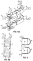
- FIG. 3A depicts in perspective view a SOFC Stick TM device 10 similar to that depicted in FIG. 1 , but having modified first and second ends 11a, 11b. Ends 11a, 11b have been machined to form cylindrical end portions to facilitate connection of the fuel supply 34 and air supply 36.
- FIG. 3B depicts in perspective view a supply tube 50 connected to the first end 11a for feeding fuel from fuel supply 34 to the fuel inlet 12.
- supply tube 50 can be a silicone or latex rubber tube that forms a tight seal by virtue of its elasticity to the first end 11a.
- the flexibility and elasticity of the supply tubes 50 can provide a shock-absorbing holder for the SOFC Stick TM devices when the use is in a mobile device subject to vibrations.
- the tubes or plates were rigidly brazed, and thus subject to crack failure if used in a dynamic environment. Therefore, the additional function of the supply tubes 50 as vibration dampers offers a unique advantage compared to the prior art.
- contact pads 44 are provided on the outer surface of the SOFC Stick TM device 10 so as to make contact with the exposed anode portion 25 and the exposed cathode portion 27.
- Material for the contact pads 44 should be electrically conductive so as to electrically connect the voltage nodes 38, 40 to their respective anode 24 and cathode 26. It may be appreciated that any suitable method may be used for forming the contact pads 44. For example, metal pads may be printed onto the outer surface of a sintered SOFC Stick TM device 10. The wires 42 are secured to the contact pads 44 by a solder connection 46, for example, to establish a reliable connection.
- Solders are a low temperature material, which can be used by virtue of being located in the cold zones 30 of the SOFC Stick TM device 10.
- a common 10Sn88Pb2Ag solder can be used.
- the present invention eliminates the need for high temperature voltage connections, thereby expanding the possibilities to any low temperature connection material or means.
- FIG. 3A in perspective view, are the fuel outlet 16 and the air outlet 22.
- the fuel enters through the fuel inlet 12 at first end 11a, which is in one cold zone 30, and exits out the side of SOFC Stick TM device 10 through outlet 16 adjacent the second end 11b.
- Air enters through air inlet 18 located in the second end 11b, which is in the cold zone 30, and exits from the air outlet 22 in the side of the SOFC Stick TM device 10 adjacent the first end 11a.
- the outlets 16 and 22 are depicted as being on the same side of the SOFC Stick TM device 10, it may be appreciated that they may be positioned at opposing sides, for example, as depicted below in FIG. 4A .
- the air outlet 22 functions as a heat exchanger, usefully pre-heating the fuel that enters the device 10 through fuel inlet 12 (and similarly, fuel outlet 16 pre-heats air entering through air inlet 18).
- Heat exchangers improve the efficiency of the system.
- the transition zones have overlapping areas of spent air and fresh fuel (and spent fuel and fresh air), such that heat is transferred before the fresh fuel (fresh air) reaches the hot zone.
- the SOFC Stick TM device 10 is a monolithic structure that includes a built-in heat exchanger.
- FIG. 4A there is depicted in perspective view the connection of a plurality of SOFC Stick TM devices 10, in this case two SOFC Stick TM devices, by aligning each contact pad 44 connected to the exposed anode portions 25 and soldering (at 46) a wire 42 connected to the negative voltage node 38 to each of the contact pads 44.
- the contact pads 44 that are connected to the exposed cathode portions 27 are aligned and a wire 42 connecting the positive voltage node 40 is soldered (at 46) to each of those aligned contact pads 44, as shown partially in phantom.
- connection is in the cold zone 30, and is a relatively simple connection, if one SOFC Stick TM device 10 in a multi-SOFC Stick TM system or assembly needs replacing, it is only necessary to break the solder connections to that one device 10, replace the device with a new device 10, and re-solder the wires 42 to the contract pads of the new SOFC Stick TM device 10.
- FIG. 4B depicts in an end view the connection between multiple SOFC Stick TM devices 10, where each SOFC Stick TM device 10 includes a plurality of anodes and cathodes.
- each SOFC Stick TM device 10 includes a plurality of anodes and cathodes.
- the specific embodiment depicted in FIG. 4B includes three sets of opposing anodes 24 and cathodes 26, with each anode 24 exposed at the right side of the SOFC Stick TM device 10 and each cathode exposed at the left side of the SOFC Stick TM device 10.
- a contact pad is then placed on each side of the SOFC Stick TM device 10 to contact the respective exposed anode portions 25 and exposed cathode portions 27.
- FIGS. 1-4A depicted a single anode 24 opposing a single cathode 26, it may be appreciated, as shown in FIG.
- each SOFC Stick TM device 10 may include multiple anodes 24 and cathodes 26, with each being exposed to an outer surfaces of the SOFC Stick TM device 10 for electrical connection by means of a contact pad 44 applied to the outer surface for connection to the respective voltage node 38 or 40.
- the number of opposing anodes and cathodes in the structure may be tens, hundreds and even thousands.
- FIG. 5 depicts in an end view a mechanical attachment for making the electrical connection between wire 42 and the contact pad 44.
- the SOFC Stick TM devices 10 are oriented such that one set of electrodes is exposed at the top surface of each SOFC Stick TM device 10.
- the contact pad 44 has been applied to each top surface at one end (e.g., 11a or 11b) in the cold zone 30.
- Spring clips 48 may then be used to removably secure the wire 42 to the contact pads 44.
- metallurgical bonding may be used to make the electrical connections, such as depicted in FIGS. 3A , 4A and 4B , or mechanical connection means may be used, as depicted in FIG. 5 .
- the flexibility in selecting an appropriate attachment means is enabled by virtue of the cold zones 30 in the SOFC Stick TM devices of the invention. Use of spring clips or other mechanical attachment means further simplifies the process of replacing a single SOFC Stick TM device 10 in a multi-stick assembly.
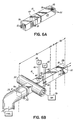
- FIGS. 6A and 6B depict in perspective views an alternative embodiment having a single cold zone 30 at the first end 11a of SOFC Stick TM device 10, with the second end 11b being in the hot zone 32.
- the SOFC Stick TM device 10 includes three fuel cells in parallel, whereas the SOFC Stick TM device 10 of FIG. 6B includes a single fuel cell.
- embodiments of the device may include a single cell design or a multi-cell design.
- the air inlet 18 is reoriented to be adjacent the first end 11 a at the side surface of the SOFC Stick TM device 10.
- the air passage 20 (not shown) again runs parallel to the fuel passage 14, but in this embodiment, the flow of air is in the same direction as the flow of fuel through the length of the SOFC Stick TM device 10.
- the air outlet 22 is positioned adjacent the fuel outlet 16. It may be appreciated that either the fuel outlet 16 or the air outlet 22, or both, can exit from a side surface of the SOFC Stick TM device 10, rather than both exiting at the end surface.
- the supply tube 50 for the air supply 36 is formed by making holes through the side of the supply tube 50 and sliding the device 10 through the side holes so that the supply tube 50 for the air supply 36 is perpendicular to the supply tube 50 for the fuel supply 34.
- a silicone rubber tube or the like may be used in this embodiment.
- a bonding material may be applied around the joint between the tube 50 and the device 10 to form a seal.
- the electrical connections are also made adjacent the first end 11a in the cold zone 30.
- FIG. 6A and 6B each depict the positive voltage connection being made on one side of the SOFC Stick TM device 10 and the negative voltage connection being made on the opposing side of the SOFC Stick TM device 10.
- the device is not so limited.
- An advantage of the single end input SOFC Stick TM device 10 is that there is only one cold-to-hot transition instead of two transition zones 31, such that the SOFC Stick TM could be made shorter.
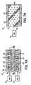
- FIGS. 7A and 7B One benefit of the device is the ability to make the active layers very thin, thereby enabling an SOFC Stick TM to incorporate multiple fuel cells within a single device.
- FIG. 7A is a cross-sectional side view
- FIG. 7B is a cross-sectional top view through the air passage 20.
- a sacrificial tape layer may be used, with a plurality of holes formed in the sacrificial layer, such as by means of laser removal of the material.
- a ceramic material is then used to fill the holes, such as by spreading a ceramic slurry over the sacrificial tape layer to penetrate the holes.
- the sacrificial material of the sacrificial layer is removed, such as by use of a solvent, leaving the ceramic pillars 54 remaining.
- large particles of a pre-sintered ceramic can be added to an organic vehicle, such as plastic dissolved in a solvent, and stirred to form a random mixture.
- the large particles may be spheres, such as 0.002 in diameter balls.
- the random mixture is then applied to the green structure, such as by printing in the areas where the fuel and air passages 14 and 20 are to be located.
- the organic vehicle leaves the structure (e.g. is burned out), thereby forming the passages, and the ceramic particles remain to form the pillars 54 that physically hold open the passages.
- the resultant structure is shown in the micrographs of FIGS. 7C and 7D .
- the pillars 54 are randomly positioned, with the average distance being a function of the loading of the ceramic particles in the organic vehicle.
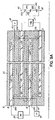
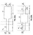
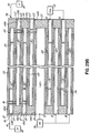
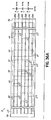
- FIG. 8A depicts in cross-section one embodiment of the invention containing two fuel cells in parallel.
- Each active electrolyte layer 28 has an air passage 20 and cathode layer 26a or 26b on one side and a fuel passage 14 and anode layer 24a or 24b on the opposing side.
- the air passage 20 of one fuel cell is separated from the fuel passage 14 of the second fuel cell by ceramic material 29.
- the exposed anode portions 25 are each connected via wire 42 to the negative voltage node 38 and the exposed cathode portions 27 are each connected via a wire 42 to the positive voltage node 40.
- a single air supply 36 can then be used to supply each of the multiple air passages 20 and a single fuel supply 34 may be used to supply each of the multiple fuel passages 14.
- the electrical circuit established by this arrangement of the active layers is depicted at the right side of the figure.
- the SOFC Stick TM device 10 is similar to that depicted in FIG. 8A , but instead of having multiple exposed anode portions 25 and multiple exposed cathode portions 27, only anode layer 24a is exposed at 25 and only one cathode layer 26a is exposed at 27.
- a first via 56 connects cathode layer 26a to cathode layer 26b and a second via 58 connects anode layer 24a to anode layer 24b.
- laser methods may be used during formation of the green layers to create open vias, which are then subsequently filled with electrically conductive material to form the via a connections.
- the same electrical path is formed in the SOFC Stick TM device 10 of FIG. 8B as in the SOFC Stick TM device 10 of FIG. 8A .
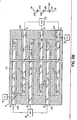
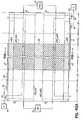
- FIGS. 9A and 9B also depict, in cross-section views, multi-fuel cell designs, but with shared anodes and cathodes.
- the SOFC Stick TM device 10 includes two fuel passages 14 and two air passages 20, but rather than having two fuel cells, this structure includes three fuel cells.
- the first fuel cell is formed between anode layer 24a and cathode layer 26a with intermediate electrolyte layer 28.
- Anode layer 24a is on one side of a fuel passage 14, and on the opposing side of that fuel passage 14 is a second anode layer 24b.
- Second anode layer 24b opposes a second cathode layer 26b with another electrolyte layer there between, thereby forming a second fuel cell.
- the second cathode layer 26b is on one side of an air passage 20 and a third cathode layer 26c is on the opposing side of that air passage 20.
- Third cathode layer 26c opposes a third anode layer 24c with an electrolyte layer 28 therebetween, thus providing the third fuel cell.
- the portion of the device 10 from anode layer 24a to cathode layer 26c could be repeated numerous times within the device to provide the shared anodes and cathodes thereby multiplying the number of fuel cells within a single SOFC Stick TM .
- Each anode layer 24a, 24b, 24c includes an exposed anode portion 25 to which electrical connections can be made at the outer surface of the SOFC Stick TM device 10 to connect to a negative voltage node 38 via a wire 42, for example.
- each cathode layer 26a, 26b, 26c includes an exposed cathode portion 27 to the outside surface for connection to a positive voltage node 40 via a wire 42, for example.
- a single air supply 36 may be provided at one cold end to supply each of the air passages 20 and a single fuel supply 34 may be provided at the opposite cold end to supply each of the fuel passages 14. The electrical circuit formed by this structure is provided at the right side of FIG. 9A .
- FIG. 9B the structure of FIG. 9A is modified to provide a single electrical connection to each of the voltage nodes to create three fuel cells in series, as shown by the circuit at the right side of FIG. 9B .
- the positive voltage node 40 is connected to cathode layer 26a at exposed cathode portion 27.
- Anode layer 24a is connected to cathode layer 26b by via 58.
- Anode layer 24b is connected to cathode layer 26c by via 56.
- Anode layer 24c is then connected at exposed anode portion 25 to the negative voltage node 38.
- this three cell structure would produce 3 volts and 1 amp for a total of 3 watts of power output.
- the SOFC Stick TM device 10 has a single cold zone 30 at the first end 11a with the second end 11 b being in the hot zone 32.
- the fuel inlets 12 are at the first end 11 a and connected to a fuel supply 34 by a supply tube 50.
- the fuel passages 14 extend the length of the SOFC Stick TM device 10 with the fuel outlet 16 being at second end 11b.
- the fuel supply connection is made in the cold zone 30 and the outlet for the fuel reactants (e.g., CO 2 and H 2 O) is in the hot zone 32.
- the anodes have an exposed anode portion 25 in the cold zone 30 for connecting to the negative voltage node 38 via a wire 42.
- the SOFC Stick TM device 10 is open at at least one side, and potentially at both opposing sides, to provide both air inlets 18 and air passages 20 in the hot zone 32.
- the use of supporting ceramic pillars 54 may be particularly useful in this embodiment within the air passages 20.
- the air outlet can be at the second end 11b, as depicted. Alternatively, although not shown, the air outlet may be at an opposing side from the air inlet side if the passages 20 extend through the width and the air supply is directed only toward the input side, or if the passages 20 do not extend through the width.
- air is also provided. In other words, the sides of the device 10 in the hot zone 32 are open to heated air instead of supplying air through a forced air tube.
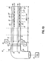
- FIG. 10A shows in side view a variation of the embodiment depicted in FIG. 10 .
- the SOFC Stick TM device 10 includes opposing cold zones 30 with a central heated zone 32 separated from the cold zones 30 by transition zones 31.
- the air inlet 18 is provided in the central heated zone 32, in at least a portion thereof, to receive the heated air.
- the air passage is not completely open to the side of the SOFC Stick TM device 10 for an appreciable length as in FIG. 10 .
- air passage 20 is open in a portion of the hot zone 32 and then is close to the sides for the remainder of the length and then exits at air outlet 22 at second end 11b of the SOFC Stick TM device 10.
- This embodiment allows heated air to be supplied in the hot zone 32 rather than a forced air supply tube, but also allows for the fuel and air to exit at one end 11b of the device 10 in a cold zone 30.
- FIG. 11 provides a key for the components depicted schematically in FIGS. 12-24 .
- fuel (F) or air (A) is shown by an arrow going into the SOFC Stick TM device, that indicates forced flow, such as through a tube connected to the input access point.
- air input is not depicted, that indicates that heated air is supplied in the hot zone by means other than a forced flow connection and the SOFC Stick TM is open to the air passage at an access point within the hot zone.
- One embodiment of the invention is an SOFC Stick TM device that includes at least one fuel passage and associated anode, at least one oxidant pathway and associated cathode, and an electrolyte therebetween, where the cell is substantially longer than it is wide or thick so as to have a dominant expansion along one dominant axis and operating with a portion thereof in a heated zone having a temperature of greater than about 400°C.
- the SOFC Stick TM device has integrated access points for both air and fuel input at one end of the device according to the dominant expansion direction, or air input at one end and fuel input at the other end according to the dominant expansion direction, and air and fuel inputs being located outside the heated zone. For example, see FIGS. 20 and 24 .
- the fuel cell has a first temperature zone and a second temperature zone, wherein the first temperature zone is the hot zone, which operates at a temperature sufficient to carry out the fuel cell reaction, and the second temperature zone is outside the heated zone and operates at a lower temperature than the first temperature zone.
- the temperature of the second temperature zone is sufficiently low to allow low temperature connections to be made to the electrodes and a low temperature connection for at least the fuel supply.
- the fuel cell structure extends partially into the first temperature zone and partially into the second temperature zone. For example, see FIGS. 12, 13 and 17 .
- the fuel cell includes a first temperature zone that is the heated zone and a second temperature zone operating at a temperature below 300°C.
- the air and fuel connections are made in the second temperature zone using rubber tubing or the like as a low temperature connection.
- Low temperature solder connections or spring clips are used to make the electrical connections to the anode and cathode for connecting them to the respective negative and positive voltage nodes.
- the fuel outlet for carbon dioxide and water and the air outlet for depleted oxygen are located in the first temperature zone, i.e., the heated zone. For example, see FIG. 17 .
- the fuel cell structure has a central first temperature zone that is the heated zone, and each end of the fuel cell is located outside the first temperature zone in a second temperature zone operating below 300°C.
- Fuel and air inputs are located in the second temperature zone, as are solder connections or spring clips for electrical connection to the anode and cathode.
- output for the carbon dioxide, water and depleted oxygen are located in the second temperature zone. For example, see FIGS. 19, 20 and 24 .
- fuel inputs may be provided at each end according to the dominant expansion direction in a second temperature zone operating below 300°C with a first temperature zone being the heated zone provided in the center between the opposing second temperature zones.
- the output for the carbon dioxide, water, and depleted oxygen may be located in the central heated zone. For example, see FIGS. 15 and 18 .
- the output for the carbon dioxide, water and depleted oxygen may be located in the second temperature zone, i.e., outside of the heated zone. For example, see FIGS. 16 and 19 .
- both the fuel and air input access points are located outside the first temperature zone, which is the heated zone, in a second temperature zone operating below 300°C thereby allowing use of low temperature connections, such as rubber tubing for air and fuel supply.
- solder connections or spring clips are used in the second temperature zone for connecting the voltage nodes to anodes and cathodes.
- the fuel and air input are both at one end according to the dominant direction, with the other end of the SOFC Stick TM being in the first heated temperature zone with the outputs of carbon dioxide, water and depleted oxygen being in the heated zone. For example, see FIG. 17 .
- the SOFC Stick TM has one heated end and one non-heated end.
- fuel and air are inputted into one end according to the dominant direction outside the heated zone and exit at the opposite end also outside the heated zone, such that the heated zone is between two opposing second temperature zones. For example, see FIG. 20 .
- fuel and air are inputted into both of opposing ends located in second temperature zones with the fuel and air outputs being in the central heated zone. For example, see FIG. 18 .
- fuel and air are inputted into both of opposing ends located in second temperature zones with the respective outputs being in the second temperature zone at the opposite end from the input.
- the fuel cell has a central heated zone and opposing ends outside the heated zone, with fuel and air both inputted into the first end with the respective reaction outputs exiting adjacent the second end, and both fuel and air being inputted into the second end and the reaction outputs exiting adjacent the first end.
- fuel input may be at one end outside the heated zone and air input may be at the opposite end outside the heat zone.
- the reaction outputs from both the air and fuel may be within the heated zone (see FIG. 21 ), or they both may be outside the heated zone adjacent the opposite end from the respective input (see FIG. 24 ).
- the carbon dioxide and water output may be in the hot zone while the depleted oxygen output is outside the hot zone (see FIG. 22 ), or conversely, the depleted oxygen output may be in the heated zone and the carbon dioxide and water output outside the heated zone (see FIG. 23 ).
- the variations with respect to fuel and air output depicted in FIGS. 22 and 23 could also be applied in the embodiments depicted in FIGS. 18-20 , for example.
- an SOFC Stick TM device 100 is provided having what may be referred to as a panhandle design.
- the SOFC Stick TM device 100 has an elongate section 102, which may be similar in dimension to the Stick TM devices depicted in prior embodiments, that has a dominant expansion along one dominant axis, i.e., it is substantially longer than it is wide or thick.
- the SOFC Stick TM device 100 further has a large surface area section 104 having a width that more closely matches the length.
- Section 104 may have a square surface area or a rectangular surface area, but the width is not substantially less than the length, such that the expansion does not have a single dominant axis in section 104, but rather has an axis in the length direction and the width direction.
- the large surface area section 104 is located in the hot zone 32, whereas the elongate section 102 is at least partially located in the cold zone 30 and the transition zone 31. In an exemplary embodiment, a portion of the elongate section 102 extends into the hot zone 32, but this is not essential.
- the fuel and air supplies may be connected to the elongate section 102 in the manner depicted in FIG. 6B , as well as the electrical connections.
- FIGS. 25B and 26A a top plan view is provided and in FIG. 26B a side view is provided of an alternative embodiment similar to that shown in FIGS. 25A , 27A and 27B but further having a second elongate section 106 opposite the elongate section 102 so as to position the large surface area section 104 between the two elongate sections 102 and 106.
- Elongate section 106 is also at least partially located in a cold zone 30 and a transition zone 31.
- fuel may be inputted into elongate section 102 and air inputted into elongate section 106.
- the air supply and the fuel supply could then be connected to the elongate sections 106 and 102, respectively, in the manner depicted in FIG. 2 or FIG. 3B .
- the air output may be located in the elongate section 102 adjacent the fuel input, and the fuel output may be located in elongate section 106 adjacent the air input.
- one or both of the air and fuel outputs may be located in the large surface area section 104 in the hot zone 32, as depicted in FIGS. 26A and 26B in top and side views, respectively.
- the surface area of the opposing anode and cathode with intervening electrolyte may be increased in the hot zone to increase the reaction area, thereby increasing the power generated by the SOFC Stick TM device 100.
- SOFC Stick TM devices 10, 100 Another benefit of the SOFC Stick TM devices 10, 100 is low weight. Typical combustion engines weigh on the order of 18-30 lbs per kW of power. An SOFC Stick TM device 10, 100 of the invention can be made with a weight on the order of 0.5 lbs per kW of power.
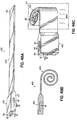
- FIGS. 28A-D depict an alternative embodiment of a Tubular SOFC Stick TM device 200 not in accord with the invention, having a spiral or rolled, tubular configuration.
- FIG. 28A is a schematic top view of device 200, in the unrolled position.
- the unrolled structure of device 200 has a first end 202 and a second end 204 of equal length L that will correspond to the length of the rolled or spiral Tubular SOFC Stick TM device 200.
- Fuel inlet 12 and air inlet 18 are shown on opposing sides adjacent first end 202.
- Fuel passage 14 and air passage 20 then extend along the width of the unrolled structure of device 200 to the second end 204 such that the fuel outlet 16 and air outlet 22 are at the second end 204, as further shown in the schematic end view of the unrolled structure of device 200 in FIG. 28B and the schematic side view of the unrolled structure of device 200 in FIG. 28C .
- the fuel passage 14 and air passage 20 are shown as extending nearly the length L of the unrolled structure of device 200 so as to maximize fuel and air flow, but the device is not so limited.
- first end 202 is then rolled toward second end 204 to form the spiral tube structure of device 200 depicted in the schematic perspective view of FIG. 28D .
- Air supply 36 may then be positioned at one end of the spiral Tubular SOFC Stick TM device 200 for input into air inlet 18, while the fuel supply 34 may be positioned at the opposite end of the spiral Tubular SOFC Stick TM device 200 to input fuel into the fuel inlet 12.
- the air and the fuel will then exit the spiral Tubular SOFC Stick TM device 200 along the length L of the device 200 through fuel outlet 16 and air outlet 22.
- the voltage nodes 38, 40 can be soldered to contact pads 44 formed on or adjacent to opposing ends of the spiral Tubular SOFC Stick TM device 200.
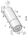
- FIGS. 29A-29G depict an alternative embodiment not in accord with the invention wherein the SOFC Stick TM device is in a tubular concentric form.
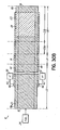
- FIG. 29A depicts in schematic isometric view a concentric Tubular SOFC Stick TM device 300.
- FIGS. 29B-29E depict cross-sectional views of the concentric device 300 of FIG. 29A .
- FIG. 29F depicts an end view at the air input end of the device 300
- FIG. 29G depicts an end view at the fuel input end of device 300.
- the particular embodiment shown includes three air passages 20, one being in the center of the tubular structure and the other two being spaced from and concentric therewith.
- the concentric Tubular SOFC Stick TM device 300 also has two fuel passages 14 between and concentric with the air passages 20.
- the concentric Tubular SOFC Stick TM device 300 includes a fuel outlet 16 connecting the fuel passages 14 at one end and an air outlet 22 connecting the air passages 20 at the other end opposite their respective inlets.
- Each air passage 20 is lined with cathodes 26 and each fuel passage 14 is lined with anodes 24, with electrolyte 28 separating opposing anodes and cathodes.
- electrical connection may be made to the exposed anodes 25 and exposed cathodes 27 at opposing ends of the concentric Tubular SOFC Stick TM device 300.
- Concentric Tubular SOFC Stick TM device 300 may include pillars 54 positioned within the air and fuel passages 14, 20 for structural support.
- the spent fuel or air is in a heated state as it exits the central hot zone 32.
- the heated air and fuel cool as they travel through the transition zones 31 to the cold zones 30.
- Thin layers of electrodes and/or ceramic/electrolyte separate an air passage from a parallel fuel passage, and vice-versa. In one passage, heated air is exiting the hot zone, and in an adjacent parallel passage, fuel is entering the hot zone, and vice-versa.
- the heated air through heat exchange principles, will heat up the incoming fuel in the adjacent parallel passage, and vice-versa.
- the SOFC Stick TM device 10 includes one cold end and one hot end, fuel and air are inputted into the same cold end and exit through the same opposing hot end, such that there is no cross-flow of fuel and air for heat-exchange to occur. Only limited heat exchange to the incoming fuel and air is available from the electrode and ceramic materials of the SOFC Stick TM device.
- FIGS. 30A-33C depict various embodiments of an SOFC Stick TM device 10 having integrated pre-heat zones 33a for heating the fuel and air before it enters an active zone 33b in which the anodes 24 and cathodes 26 are in opposing relation.
- SOFC Stick TM devices in which there are two cold ends with an intermediate hot zone and fuel and air input at opposing cold ends, and SOFC Stick TM devices in which there is one hot end and one cold end with fuel and air input both at the single cold end.
- the amount of electrode material used can be limited to the active zone 33b with only a small amount leading to the cold zone for the external connection to the voltage nodes 38, 40.
- Another benefit in these embodiments, which will be described in more detail later, is that the electrons have the shortest possible path to travel to the external voltage connection, which provides a low resistance.
- FIG. 30A depicts a schematic cross-sectional side view of a first embodiment of an SOFC Stick TM device 10 having one cold zone 30 and one opposing hot zone 32 with an integrated pre-heat zone 33a.
- FIG. 30B depicts in cross-section a view through the anode 24 looking up toward the fuel passage
- FIG. 30C depicts in cross-section a view through the cathode 26 looking down toward the air passage.
- the fuel from fuel supply 34 enters through fuel inlet 12 and extends along the length of the device 10 through fuel passage 14 and exits from the opposite end of the device 10 through fuel outlet 16.
- the cold zone 30 is at the first end 11a of SOFC Stick device 10 and the hot zone 32 is at the opposing second end 11 b. Between the hot and cold zones is the transition zone 31.
- the hot zone 32 includes an initial pre-heat zone 33a through which the fuel first travels, and an active zone 33b that includes the anode 24 adjacent the fuel passage 14. As shown in FIG. 30B , the cross-sectional area of the anode 24 is large in the active zone 33b.
- the anode 24 extends to one edge of the SOFC Stick TM device 10 and an exterior contact pad 44 extends along the outside of the device 10 to the cold zone 30 for connection to the negative voltage node 38.
- the air from air supply 36 enters through the air inlet 18 positioned in the cold zone 30 and the air extends along the length of the SOFC Stick TM device 10 through air passage 20 and exits from the hot zone 32 through the air outlet 22.
- the cathode 26 is positioned in the active zone 33b in opposing relation to the anode 24 and extends to the opposite side of the SOFC Stick TM device 10 where it is exposed and connected to an external contact pad 44 that extends from the active hot zone 33b to the cold zone 30 for connection to the positive voltage node 40. It is not necessary, however, that the exposed cathode 27 be on an opposite side of the device 10 as the exposed anode 25.
- the exposed anode 25 and exposed cathode 27 could be on the same side of the device and the contact pads 44 could be formed as stripes down the side of the SOFC Stick TM device 10.
- the air and fuel are first heated in the pre-heat zone 33a, where no reaction is taking place, and the majority of the anode and cathode material is limited to the active zone 33b where the heated air and fuel enters and react by virtue of the opposed anode and cathode layers 24, 26.
- FIGS. 31A-31C The embodiment depicted in FIGS. 31A-31C is similar to that depicted in FIGS. 30A-30C , but rather than having one hot end and one cold end, the embodiment of FIGS. 31A-C includes opposing cold zones 30 with a central hot zone 32.
- Fuel from fuel supply 34 enters through the first end 11a of device 10 through fuel inlet 12 in the cold zone 30 and exits from the opposite second end 11b through fuel outlet 16 positioned in the opposing cold zone 30.
- air from air supply 36 enters through the opposite cold zone 30 through air inlet 18 and exits at the first cold zone 30 through air outlet 22.
- the fuel enters the hot zone 32 and is pre-heated in pre-heat zone 33a, while the air enters at the opposite side of the hot zone 32 and is pre-heated in another pre-heat zone 33a. There is thus a cross-flow of fuel and air.
- the anode 24 opposes the cathode 26 in an active zone 33b of hot zone 32 and the reaction occurs in the active zone 33b involving the pre-heated fuel and air. Again, the majority of electrode material is limited to the active zone 33b.
- the anode is exposed at one edge of the SOFC Stick TM device 10, and the cathode is exposed at the other side of device 10.
- An external contact pad 44 contacts the exposed anode 25 in the hot zone 32 and extends toward the first cold end 11a for connection to negative voltage node 38. Similarly, an external contact pad 44 contacts the exposed cathode 27 in hot zone 32 and extends toward the second cold zone 11b for connection to positive voltage node 40.
- the pre-heat zones 33a provide the advantage of fully heating the gas to the optimal reaction temperature before it reaches the active region. If the fuel is colder than the optimum temperature, the efficiency of the SOFC system will be lower. As the air and fuel continue on their paths, they warm up. As they warm up, the efficiency of the electrolyte increases in that region. When the Fuel, air and electrolyte reach the full temperature of the furnace, then the electrolyte is working under its optimal efficiency. To save money on the anode and cathode, which may be made out of precious metal, the metal can be eliminated in those areas that are still below the optimal temperature.
- the amount of the pre-heat zone in terms of length or other dimensions, depends on the amount of heat transfer from the furnace to the SOFC Stick TM device, and from the SOFC Stick TM device to the fuel and air, as well as whether any heat exchange is occurring due to cross-flow of the fuel and air.
- the dimensions further depend on the rate of flow of fuel and air; if the fuel or air is moving quickly down the length of the SOFC Stick TM device, a longer pre-heat zone will be advantageous, whereas if the flow rate is slow, the pre-heat zone may be shorter.
- FIGS. 32A and 32B depict an embodiment similar to that shown in FIGS. 31A-31C , but the SOFC Stick TM device 10 includes a pre-heat chamber 13 between the fuel inlet 12 and fuel passage 14 that extends into the hot zone 32 for pre-heating in the pre-heat zone 33a a large volume of fuel before it passes through the more narrow fuel passage 14 into the active zone 33b.
- the SOFC Stick TM device 10 similarly includes a pre-heat chamber 19 between the air inlet 18 and the air passage 20 that extends into the hot zone 32 for pre-heating a large volume of air in the pre-heat zone 33a before it passes through the more narrow air passage 20 to the active zone 33b.
- the SOFC Stick TM device 10 may include multiple fuel passages 14 and air passages 20, each of which would receive flow from a respective pre-heat chamber 13, 19.
- Such a cavity or pre-heat chamber could be prepared in a number of different ways, including taking a green (i.e., before sintering) assembly and drilling into the end of the assembly to form the chamber, or by incorporating a large mass of organic material within the green stack as it is formed, whereby the organic material is baked out of the SOFC Stick TM device during sintering.
- FIGS. 33A-33C depict yet another embodiment for pre-heating the air and fuel prior to the air and fuel reaching the active zone 33b.
- FIG. 33A is a schematic cross-sectional side view, essentially through the longitudinal center of the SOFC Stick TM device 10.
- FIG. 33B is a cross-sectional top view taken along the line 33B-33B where the fuel passage 14 and anode 24 intersect
- FIG. 33C is a cross-sectional bottom view taken along the line 33C-33C where the air passages 20 intersects the cathode 26.
- the SOFC Stick TM device 10 has two opposing cold zones 30 and a central hot zone 32, with a transition zone 31 between each cold zone 30 and the hot zone 32.
- the portion of the fuel passage 14 and air passage 20 from the initial entry into the hot zone 32 through the bend (U-turn) constitute a pre-heat zone for heating the fuel and air.
- the passages are lined with a respective anode 24 or cathode 26, which are in opposing relation with an electrolyte 28 therebetween, which region constitutes the active zone 33b in hot zone 32.
- the fuel and air is heated in the pre-heat zone 33a prior to entry into the active zone 33b to increase the efficiency of the SOFC Stick TM device 10, and to minimize the usage of electrode material.
- the anode 24 is extended to the exterior of the device 10 in the cold zone 30 for connection to negative voltage node 38.
- cathode 26 is extended to the exterior of the device 10 for electrical connection to positive voltage node 40.
- the fuel and air outlets 16 and 22 also may exit from the cold zones 30.
- the anodes 24 and cathodes 26 travel within the layers of the SOFC Stick TM device 10, essentially in the center area of each layer, i.e., internal to the device, until they reach the end of the device. At that point, the anodes 24 and cathodes 26 are tabbed to the outside of the SOFC Stick TM device 10 where the exposed anode 25 and exposed cathode 27 are metallized with a contact pad, such as by applying a silver paste, and then a wire is soldered to the contact pad. For example, see FIGS. 4A-4B . It may be desirable, however, to build up the layers in the SOFC Stick TM device 10 into higher voltage combinations, for example as shown in FIGS.
- FIGS. 34A to 37 Alternative embodiments for interconnecting the electrode layers are depicted in FIGS. 34A to 37 .
- these alternative embodiments use exterior stripes (narrow contact pads), for example of silver paste, along the sides of the SOFC Stick TM device 10, in particular, multiple small stripes.
- the striping technique Using the striping technique, a simple structure is formed that can provide series and/or parallel combinations to achieve any current/voltage ratios needed.
- the external stripes will have loose mechanical tolerances compared to the internal vias, thereby simplifying manufacturing.
- the external stripes will likely have a lower resistance (or equivalent series resistance) than the vias. Lower resistance in a conductor path will result in lower power loss along that path, such that the external stripes provide the ability to remove the power from the SOFC Stick TM device 10 with a lower loss of power.
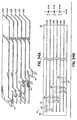
- FIG. 34A provides a schematic oblique front view of the alternating anodes 24a, 24b, 24c and cathodes 26a, 26b, 26c.
- the anodes 24a, 24b, 24c and cathodes 26a, 26b, 26c include a tab out to the edge of the device 10 to provide the exposed anodes 25 and exposed cathodes 27.
- An external contact pad 44 (or stripe) is then provided on the outside of the SOFC Stick TM device over the exposed anodes 25 and cathodes 27, as best shown in the schematic side view of FIG.
- the SOFC Stick TM device 10 provides 3 volts and 1 amp.
- the structure is doubled and the two structures are connected by long stripes down the sides of the device 10, thereby providing an external anode/cathode interconnect in a series parallel design that provides 3 volts and 2 amps.
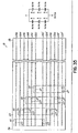
- FIGS. 36A and 36B provide an embodiment for a low equivalent series resistance path for providing low power loss.
- the hot zone 32 is in the center of the SOFC Stick TM device 10 with the first end 11a and second end 11b being in cold zones 30. Fuel is inputted through fuel inlets 12 in first end 11a and air is inputted through air inlets 18 in second end 11b.
- the hot zone 32 which is the active area of the SOFC Stick TM device 10
- the anodes 24 and cathodes 26 are exposed to the sides of the device, with the anodes 24 exposed to one side, and the cathodes 26 exposed to the opposite side.
- Contact pads 44 (or stripes) are applied over the exposed anodes 25 and cathodes 27.
- the edges of the SOFC Stick TM device 10 are metallized along the length of the sides of the device 10 until the metallization reaches the cold zones 30, where the low temperature solder connection 46 is made to the negative voltage node 38 and the positive voltage node 40.
- the anodes 24 and cathodes 26 cannot be optimized only for low resistance because they have other functions.
- the electrodes must be porous to allow the air or fuel to pass through to the electrolyte, and porosity increases resistance. Further, the electrodes must be thin to allow for good layer density in a multi-layer SOFC Stick TM device 10, and the thinner the electrode, the higher the resistance.
- the long contact pads 44 along the exterior of the SOFC Stick TM device that extend to the cold zones 30 allow for the power to be removed from the SOFC Stick TM device 10 with a lower loss by providing a lower resistance conductor path.
- the striping technique may be used in the active area (hot zone 32) of the SOFC Stick TM device 10 for making series and parallel connections to increase power, and a long stripe down the side of the device to the cold ends allows that powder to be efficiently removed from the SOFC Stick TM device 10.
- FTG. 37 depicts, in schematic isometric view, an embodiment similar to that depicted in FIG. 36B , but having a single cold zone 30 at the first end 11a of the SOFC Stick TM device 10, with the hot zone 32 being at the second end 11b of device 10.
- Multiple vertical stripes or contact pads 44 are provided within the hot zone 32 to make the series and/or parallel connections, and the horizontal long stripes 44 down the sides of the device 10 are provided from the hot zone 32 to the cold zone 30 for making the low temperature solder connections 46 to the positive voltage node 40 and negative voltage node 38.
- One method for forming the fuel passages 14 and air passages 20 is to place, an organic material within the green, layered structure that can then bake out during a later sintering step.
- the SOFC Stick TM To build individual SOFC Sticks TM having high power output, such as 1 KW or 10 KW output, the SOFC Stick TM must be long, wide and have a high layer count. By way of example, the SOFC Stick TM devices may be on the order of 12 inches to 18 inches long.
- the organic material used to form the fuel passage 14 must exit through openings 12 and 16 that form the fuel inlet and fuel outlet, respectively.
- the organic material used to form the air passage 20 must bake out through the openings 18 and 22 that form the air inlet and air outlet, respectively.
- FIGS. 38A and 38B depict, in schematic cross-sectional side view, an alternative embodiment that provides multiple exit gaps for bake-out of the organic material 72.
- multiple openings 70 arc provided on one side of the SOFC Stick TM device 10 to provide multiple bake-out paths for the organic material 72 to exit the structure.
- the multiple openings 70 are then closed by applying a barrier coating 60 to the side of the SOFC Stick TM device 10.
- the barrier coating may be a glass coating.
- the barrier coating may be a glass containing a ceramic filler.
- the barrier coating 60 may be a contact pad 44, for example filled with paste, which would then also serve as the low resistance path for the generated power.
- the silver paste may also contain glass for increased adhesion.
- the bake-out paths for the cathode are vented to one side of the SOFC Stick TM device 10 and the bake-out paths for the anode are vented to the opposing side of the device 10 to avoid shorting between opposite electrodes.
- the cathode and air channel may be combined and the anode and fuel channel may be combined through use of porous electrode materials that permit flow of the air or fuel.
- the cathodes and anodes must be porous anyway to permit the reaction to occur, so in combination with forced air and fuel input, sufficient flow could be achieved through the SOFC Stick TM device to permit the power generating reaction to occur.
- FIG. 39 Another embodiment not in accord with the present invention is depicted in schematic cross-sectional end view in FIG. 39 .
- This embodiment is essentially an anode-supported version of an SOFC Stick TM device 10.
- the SOFC Stick TM device 10 may have a hot end and a cold end or two cold ends with an intermediate hot zone.
- the anode-supported version uses the anode material as the supporting structure.
- a fuel passage 14 and an air passage 20 are provided in opposing relation.
- the air channel 20 is lined with an electrolyte layer 28, and then with a cathode layer 26. Chemical vapor deposition could be used to deposit the internal layers, or by using solutions of viscous pastes.
- FIGS. 40A and 40B a further embodiment is shown for an anode-supported version of the SOFC Stick TM device 10.
- the separate open fuel passage 14 is eliminated, such that the porous anode 24 also serves as the fuel passage 14.
- the SOFC Stick TM device 10 is coated with a barrier coating 60, such as a glass coating or a ceramic coating, to prevent the fuel from exiting out the sides of the device 10.
- the SOFC Stick TM device 10 may have as many air passages with associated electrolyte and cathode in the anode structure as desired. As depicted in FIG.
- the fuel from fuel supply 34 is forced into first end 11a through the porous anode 24, which serves as the fuel passage 14, and passes through the electrolyte layers 28 and the cathodes 26 to react with air from air supply 36, and the spent air and fuel can then exit out the air outlet 22.
- the SOFC Stick TM device 10 may include a plurality of air passages 20 provided within the anode-supporting structure, and a single fuel passage 14 normal to the multiple air passages 20 for feeding fuel from the fuel supply 34 through the single fuel inlet 12 to multiple air passages 20.
- the air passages 20 are lined first with an electrolyte layer 28 and then with a cathode 26.
- the fuel passes from the single fuel passage 14 through the anode structure 24, through the electrolyte 28, and through the cathode 26 to react with the air in the air passage 20, and the spent fuel and air exits from the air outlet 22.
- the spent fuel can also seep out the side of the SOFC Stick TM device 10 that does not include the barrier coating 60, which uncoated side would be located on the opposing side of the device from the orientation of the single fuel passage 14.
- the structure may be essentially reversed to be a cathode-supported structure.
- Fuel channels coated with an electrolyte layer and an anode layer would then be provided within the cathode structure.
- a separate air channel or multiple air channels could also be provided, or the porosity of the cathode could be used for the air flow.
- FIGS. 42A-42C depict a method for forming the electrodes within the air and fuel passages.
- the SOFC Stick TM device 10 is first built without the electrodes.
- green ceramic material is used to form the electrolyte and ceramic supporting portions of the SOFC Stick TM and the organic material is used to form the passages, such as fuel passage 14.
- the fuel passage 14 is filled with an anode paste or solution.
- the paste may be thick like that of a printing ink, or runny like that of a high-content water solution.
- the anode material can be filled into the fuel passage 14 by any desired means, such as sucking it in via a vacuum, by capillary forces, or forcing it in via air pressure.
- the anode material is dissolved in solution, flowed into the fuel passage 14, and then precipitated, For example, through a change of pH, the anode particles can be precipitated and the solution drawn out.
- the anode particles can be simply allowed to settle, and then the liquid dried or baked out of the fuel passage 14. This settling can be accomplished by creating an ink or liquid carrier that will not keep the particles in suspension for any extended period of time, for example, due to low viscosity.
- a centrifuge could also be used to force the settling. The centrifuge can easily allow preferential settling of most particles onto one surface of the fuel passage 14 to thereby conserve electrode material and to ensure that only one surface of the fuel passage 14 acts as an electrolyte.
- the anode particle-containing solution 66 is pulled into the fuel passage 14 until the passage 14 is completely filled, as shown in FIG. 42B .
- the particles then settle to the bottom of the passage 14 to form an anode layer 24, as shown in FIG. 42C .
- Flooding in of the solution 66 can be accelerated by gravity, vacuum, or centrifuge, as compared to normal capillary forces.
- the anode 24 and fuel passage 14 were used as an example, any of these alternative, embodiments may also be used with a cathode paste or solution to create a cathode layer 26 in an air passage 20.
- a ceramic electrode material (anode or cathode) could be infused into the passage (fuel or air) in a liquid sol-gel state, and then deposited inside the passage. It is also possible to repeat the filling operation multiple times, such as in the case where the concentration of the desired electrode material in the liquid is low, or to provide a gradient of properties in the electrode (such as to provide a different amount of YSZ in the electrode close to the electrolyte versus the amount of YSZ in the electrode farther from the electrolyte), or if there is a desire to put multiple layers of dissimilar materials together (such as a cathode made of LSM near the electrolyte, and then silver over the top of the LSM for better conductivity).
- ceramic particles may also be used to increase the effective surface area for a greater reaction area, thus giving a higher output.
- Very fine-sized ceramic balls or particles can be used inside the fuel passage 14 and the air passage 20 prior to applying the electrode layer.
- surface particles 62 line the passage 14 to provide the electrolyte layer 28 with an uneven topography that increases the surface area available to receive the electrode layer.
- the anode 24 is then applied over the uneven topography with the anode material coating all around the surface particles 62 thereby increasing the reaction area.
- the electrolyte layer 28 may be laminated so as to provide the uneven topography or textured surface layer 64, such as by pressing the green electrolyte layer against a fine grading having a V-shaped pattern, which pattern is then imparted to the electrolyte layer 28.
- the anode layer 24 may then be applied, such as by using the backfill process described above in FIGS. 42A-42C , to provide an anode with a high reaction area.
- FIGS. 45A and 45B Yet another embodiment is depicted in FIGS. 45A and 45B .
- FIG. 45A is a schematic top view depicting the air and fuel flow through air and fuel passages and the arrangement of the electrodes
- FIG. 45B is a cross-sectional view through the hot zone 32.
- the device is divided into a left side 80 and a right side 82 with an intermediate or bridging portion 84 therebetween.
- a plurality of air passages 20L extend from the first end 11a of SOFC Sticks device 10 along the length through the left side 80 and exit out the left side 80 adjacent second end 11 b, and a plurality of air passages 20R extend from first end 11a along the length through the right side 82 and exit the SOFCS Stick TM device 10 on the right side adjacent the second end 11b.
- the air passages 20L are offset from the air passages 20R, as best shown in FIG. 45B .
- a plurality of fuel passages 14L extend from the second end 11b of SOFC Stick TM device 10 along the length through the left side 80 and exit on the left side 80 adjacent first end 11a, and a plurality of fuel passages 14R extend from second end 11b along the length through the right side 82 and exit the right side 82 adjacent first end 11a.
- the fuel passages 14L are offset from the fuel passages 14R.
- each fuel passage 14L is paired with and slightly offset from an air passage 20R and each air passage 20L is paired with and slightly offset from a fuel passage 14R.
- a metallization extends along each fuel passage 14L from the left side 80 to the right side 82, where it then extends along the slightly offset air passage 20R.
- a metallization extends along each air passage 20L from the left side 80 to the right side 82, where it then extends along the slightly offset fuel passage 14R.
- the metallization serves as an anode 24L or 24R when the metallization extends along a fuel passage 14L or 14R, and the metallization serves as a cathode 26L or 26R when the metallization extends along an air passage 20L or 20R,
- the metallization simply serves as a bridge 90 between an anode and a cathode.
- the metallization may comprise the same material along its length, such that the anode 24L or 24R, the bridge 90 and the cathode 26L or 26R each comprise the same material.
- the metallizations may each comprise platinum metal, which functions well as either an anode or a cathode.
- the metallization may comprise different materials.
- the cathodes 26R or 26L may comprise lanthanum strontium manganite (LSM), while the anodes 24R or 24L comprise nickel, NiO, or NiO+YSZ,
- the bridges 90 may comprise palladium, platinum, LSM, nickel, NiO, or NiO+YSZ.
- the present invention contemplates any combination or type of materials suitable for use as a cathode or an anode, or a bridging material therebetween, and the invention is not limited to the specific materials identified above.
- a fuel channel 14R is provided with an associated anode 24R that extends to the right edge of the SOFC Stick TM device 10 to provide the external exposed anode 25.
- anode 24R need not extend into the left side 80.
- an exterior contact pad 44 is applied over the exposed anode 25 and extends along the length of the SOFC Stick TM device into the cold zone 30. Negative voltage node 38 can then be connected by wire 42 and solder connection 46 to the contact pad 44.
- the anode 24R could extend, as shown, to the right edge throughout the hot zone 32, or could just extend in a small tab portion to reduce the amount of electrode material used. Also, the anode 24R could extend to the right edge of the SOFC Stick TM device 10 along the length of the fuel passage 14R, although such embodiment would involve an unnecessary use of electrode material.
- a single air passage 20L is provided with an associated cathode 26L that extends to the left side of the SOFC Stick TM device 10 to form the exposed cathode 27.
- This air passage 20L is not associated with an offset fuel passage 14R, and it is not necessary that the cathode 26L extend to the right side 82.
- a contact pad 44 may be applied along the exterior of the left side 80 of the SOFC Stick TM device 10 from the exposed cathode 27 to a cold end 30, where a positive voltage node 40 may be connected via wire 42 and solder connection 46 to the contact pad 44.
- the single fuel passage 14R and associated anode 24R are shown at the top of the right side 82, while the single air passage 20L and associated cathode 26L are shown at the bottom of the left side 80 of the SOFC Stick TM device 10.
- the invention is not limited to that arrangement.
- air passage 20L and associated cathode 26L could be provided also at the top of device 10 on the left side 80, in a similar offset manner to the single fuel passage 14R and its associated anode 24R, but the metallization would not run from the left side 80 through the bridging portion 84 to the right side 82. Rather, the bridge 90 would be absent such that the anode 24R is electrically separated from the cathode 26L.
- an SOFC Stick TM device 10 may be provided with two unique air pathway stacks and two unique fuel pathway stacks within a single SOFC Stick TM device 10, with the cells connected in series.
- the embodiment depicted in FIGS. 45A and 45B has an advantage of raising the voltage without raising the current, and while maintaining a low resistance. Further, this embodiment provides a high density within the SOFC Stick TM device 10.
- FIGS. 46A and 46B an alternative embodiment is depicted in schematic perspective view and schematic cross-sectional view, respectively.
- Previous embodiments e.g., FIG. 37
- Previous embodiments provided external stripes along the exterior sides or edges of the SOFC Stick TM device 10 from the hot zone 32 to the cold zone(s) 30 to provide a path of low resistance for the electrons to travel to the cold-end.
- a contact pad 44 is applied along one side and one of the top and bottom surfaces for the external connection to the anode 24 and another contact pad 44 is applied along the opposing side and the other of the top and bottom surfaces for the external connection to the cathode 26.
- the electrons have a large or wide path along which to travel, thereby providing an even lower resistance.
- These large conductor pads 44 that are applied on two adjacent surfaces could be used in any of the embodiments disclosed herein.
- FIG. 47 yet another embodiment is depicted, in schematic cross-sectional side view, of an SOFC Stick TM device 10 that takes advantage of heat exchange principles.
- the fuel passage 14 and air passage 20 are joined into a single exhaust passage 21. Any un-reacted fuel will bum when combined with the heated air, thus producing additional heat.
- the exhaust passage 21 travels back toward the cold zone 30 adjacent the active zone 33b, with the direction of flow of the exhaust (spent fuel and air) being opposite that of the incoming fuel and air in the adjacent fuel and air passages 14, 20.
- the additional heat generated in the exhaust passage 21 is transferred to the adjacent passages 14, 20 to heat the incoming fuel and air.
- FIGS. 48A-48C depict an "end-rolled SOFC Stick TM device" 400 (not in accord with the invention) having a thick portion 402 having a greater thickness than a thin portion 404, as depicted in FIG. 48A .
- the fuel and air inlets 12, 18 are positioned adjacent first end 11a, which is at the end of thick portion 402, and while not shown, the air and fuel outlets (16, 22) may be provided at the sides of the device 400 adjacent opposing second end 11b, which is at the end of the thin portion 404.
- the thick portion 402 should be thick enough to provide mechanical strength. This may be achieved by providing thick ceramic 29 around the adjacent fuel and air inlets 12, 18.
- the thin portion 404 will include the active zone 33b (not shown) that includes an anode (not shown) in opposing relation to a cathode (not shown) with an electrolyte (not shown) therebetween (as in prior embodiments).
- the thin portion 404 should be thin enough to permit it to be rolled while in the green (unfired) state, as shown in FIG. 48B .
- the device 400 is fired.
- the rolled thin portion 404 can then be heated to cause the reaction, while the thick portion 402 is a cold end, as discussed in other embodiments.
- the end-rolled SOFC Stick TM device 400 is a large surface area device that can fit in a small space by virtue of rolling the thin portion 404.
- the thin cross-section of the active zone (33b) in the thin portion 404 reduces the heat transfer out along the ceramic and allows good temperature cycle performance.
Description
- This invention relates to solid oxide fuel cell devices and systems, and methods of manufacturing the devices, and more particularly, to a solid oxide fuel cell device in the form of a multi-layer monolithic SOFC Stick™.
- Ceramic tubes have found a use in the manufacture of Solid Oxide Fuel Cells (SOFCs). There are several types of fuel cells, each offering a different mechanism of converting fuel and air to produce electricity without combustion. In SOFCs, the barrier layer (the "electrolyte") between the fuel and the air is a ceramic layer, which allows oxygen atoms to migrate through the layer to complete a chemical reaction. Because ceramic is a poor conductor of oxygen atoms at room temperature, the fuel cell is operated at 700°C to 1000°C, and the ceramic layer is made as thin as possible,
- Early tubular SOFCs were produced by the Westinghouse Corporation using long, fairly large diameter, extruded tubes of zirconia ceramic. Typical tube lengths were several feet long, with tube diameters ranging from 1/4 inch to 1/2 inch. A complete structure for a fuel cell typically contained roughly ten tubes. Over time, researchers and industry groups settled on a formula for the zirconia ceramic which contains 8 mol% Y2O3. This material is made by, among others, Tosoh of Japan as product TZ-8Y.
- Another method of making SOFCs makes use of flat plates of zirconia stacked together with other anodes and cathodes, to achieve the fuel cell structure. Compared to the tall, narrow devices envisioned by Westinghouse, these flat plate structures can be cube shaped, 6 to 8 inches on an edge, with a clamping mechanism to hold the entire stack together.
- A still newer method envisions using larger quantities of small diameter tubes having very thin walls. The use of thin walled ceramic is important in SOFCs because the transfer rate of oxygen ions is limited by distance and temperature. If a thinner layer of zirconia is used, the final device can be operated at a lower temperature while maintaining the same efficiency. Literature describes the need to make ceramic tubes at 150µm or less wall thickness.
- There are several main technical problems that have stymied the successful implementation of SOFCs. One problem is the need to prevent cracking of the ceramic elements during heating. For this, the tubular SOFC approach is better than the competing "stack" type (made from large, flat ceramic plates) because the tube is essentially one-dimensional. The tube can get hot in the middle, for example, and expand but not crack. For example, a tube furnace can heat a 36" (91.44 cm) long alumina tube, 4" (10.16 cm) in diameter, and it will become red hot in the center, and cold enough to touch at the ends. Because the tube is heated evenly in the center section, that center section expands, making the tube become longer, but it does not crack. A ceramic plate heated in the center only would quickly break into pieces because the center expands while the outside remains the same size. The key property of the tube is that it is uniaxial, or one-dimensional.
- A second key challenge is to make contact to the SOFC. The SOFC ideally operates at high temperature (typically 700-1000°C), yet it also needs to be connected to the outside world for air and fuel, and also to make electrical connection. Ideally, one would like to connect at room temperature. Connecting at high temperature is problematic because organic material cannot be used, so one must use glass seals or mechanical seals. These are unreliable, in part, because of expansion problems. They can also be expensive.
- Thus, previous SOFC systems have difficulty with at least the two problems cited above. The plate technology also has difficulty with the edges of the plates in terms of sealing the gas ports, and has difficulty with fast heating, as well as cracking. The tube approach resolves the cracking issue but still has other problems. An SOFC tube is useful as a gas container only. To work it must be used inside a larger air container. This is bulky. A key challenge of using tubes is that you must apply both heat and air to the outside of the tube; air to provide the O2 for the reaction, and heat to accelerate the reaction. Usually, the heat would be applied by burning fuel, so instead of applying air with 20% O2 (typical), the air is actually partially reduced (partially buried to provide the heat) and this lowers the driving potential of the cell.
- An SOFC tube is also limited in its scalability. To achieve greater kV output, more tubes must be added. Each tube is a single electrolyte layer, such that increases are bulky. The solid electrolyte tube technology is further limited in terms of achievable electrolyte thinness. A thinner electrolyte is more efficient. Electrolyte thickness of 2 µm or even 1 µm would be optimal for high power, but is very difficult to achieve in solid electrolyte tubes. It is note that a single fuel cell area produces about 0.5 to 1 volt (this is inherent due to the driving force of the chemical reaction, in the same way that a battery gives off 1.2 volts), but the current, and therefore the power, depend on several factors. Higher current will result from factors that make more oxygen ions migrate across the electrolyte in a given time. These factors are higher temperature, thinner electrolyte, and larger area.
-
JP 2000164239 - The present invention provides a solid oxide fuel cell device comprising an elongate substrate having an exterior surface, an interior structure and a length that is the greatest dimension whereby the elongate substrate exhibits thermal expansion along a dominant axis that is coextensive with the length, an active reaction zone along a first portion of the length configured to be exposed to a heat source to heat the active reaction zone to an operating reaction temperature, a plurality of fuel passages each having an associated anode in the active reaction zone, a plurality of oxidizer passages each having an associated cathode in the active reaction zone positioned in opposing relation to a respective one of the associated anodes, and an electrolyte disposed between each of the opposing anodes and cathodes in the active reaction zone, the anodes and cathodes each having an electrical pathway extending from within the interior structure to the exterior surface, wherein the interior structure is a ceramic support structure, the electrolyte in the active reaction zone forming part of the ceramic support structure, and the substrate has at least one inactive cold zone along a second portion of the length lacking the opposing anodes and cathodes and configured to not be exposed to the heat source to remain at a low temperature below the operating reaction temperature when the active reaction zone is heated, the plurality of fuel passages and the plurality of oxidizer passages extending within the interior structure of the elongate substrate from the at least one inactive cold zone to the active reaction zone, characterized in that the electrical pathways for each of the opposing anodes and cathodes include one of (a) an exposed anode portion and exposed cathode portion at the exterior surface in the at least one inactive cold zone for electrical connection at the low temperature below the operating reaction temperature, or (b) an exposed anode portion and exposed cathode portion at the exterior surface in the active reaction zone and a respective exterior metallization area over and in electrical contact with each of the exposed anode and cathode portions and extending along the exterior surface into the at least one inactive cold zone for electrical connection at the low temperature below the operating reaction temperature.
- The invention further provides a fuel cell system incorporating a plurality of the fuel devices, each device positioned with the first portion in a hot zone chamber and the at least one cold zone extending outside the hot zone chamber. A heat source is coupled to the hot zone chamber and adapted to heat the reaction zones of the devices to the operating reaction temperature within the hot zone chamber. The system further includes a fuel supply coupled outside the hot zone chamber to the at least one cold zones in fluid communication with the fuel passages for supplying a fuel flow into the fuel passages.
- There is also disclosed a method of making a solid oxide fuel cell device. The method includes providing an elongate monolithic sintered ceramic substrate that has a length that is the greatest dimension whereby the elongate substrate exhibits expansion along only one dominant axis that is coextensive with the length, and the elongate substrate includes a plurality of first passages and a plurality of second passages positioned in opposing relation to a respective one of the plurality of first passages. The first passages are then filled with a fluid anode material comprising anode particles and a first liquid, and then the first liquid is removed to thereby form a layer of anode particles on a surface of each of the first passages. The second passages are also filled with a fluid cathode material comprising cathode particles and a second liquid, followed by removing the second liquid to thereby form a layer of anode particles on a surface of each of the second passages.
- The accompanying drawings, which are incorporated in and constitute a part of this specification, illustrate embodiments of the invention and, together with a general description of the invention given above, and the detailed description given below, serve to explain the invention.
-
FIG. 1 and 1A depict, in side cross-sectional view and top cross-sectional view, respectively, one embodiment of a basic SOFC Stick™ device, having a single anode layer, cathode layer and electrolyte layer, and a hot zone between two end cold zones. -
FIG. 2 depicts in perspective view a first end of one embodiment of a SOFC Stick™ device with a fuel supply tube connected thereto. -
FIG. 3A depicts in perspective view a SOFC Stick™ device according to one embodiment, but having modified ends. -
FIG. 3B depicts in perspective view a fuel supply tube connected to one modified end of the device ofFIG. 3A . -
FIG. 4A depicts in perspective view a metallurgical bonding attachment means to a plurality of SOFC Stick™ devices to make electrical connection to positive and negative voltage nodes according to one embodiment. -
FIG. 4B depicts in schematic end view a connection between multiple SOFC Stick™ devices according to one embodiment, where each SOFC Stick™ device includes a plurality of anodes and cathodes. -
FIG. 5 depicts in schematic end view a mechanical attachment means for making the electrical connection to positive and negative voltage nodes according to one embodiment. -
FIGS. 6A and 6B depict in perspective views an alternative embodiment having a single cold zone at one end of a SOFC Stick™ device to which fuel and air supply tubes are attached, with the other end being in the hot zone. -
FIGS. 7A and 7B are cross-sectional side and top views, respectively, illustrating a plurality of support pillars in the air and fuel passages according to one embodiment. -
FIGS. 7C and 7D are micrographs depicting the use of spherical balls in the fuel and air passages as the support pillars according to another embodiment. -
FIG. 8A depicts in cross-section one embodiment of the invention containing two fuel cells connected externally in parallel. -
FIG. 8B depicts in cross-sectional view another embodiment of the invention similar toFIG. 8A , but having the two fuel cells connected internally in parallel through the use of vias. -
FIGS. 9A and9B depict in cross-sectional views a multi-fuel cell design according to an embodiment of the invention having shared anodes and cathodes, whereFIG. 9A depicts three fuel cell layers connected in parallel andFIG. 9B depicts three fuel cells connected in series. -
FIG. 10 depicts in schematic side view an SOFC Stick™ device according to one embodiment of the invention having a fuel supply tube connected to a cold end of the device and a side of the device open in the hot zone to an air passage for supply of heated air to the device in the hot zone. -
FIG. 10A depicts in schematic side view a variation of the embodiment ofFIG. 10 , where the hot zone is positioned between opposing cold ends. -
FIG. 10B depicts the SOFC Stick™ device ofFIG. 10A in top cross-sectional view taken alongline 10B-10B. -
FIGS. 11-24 schematically depict various embodiments of the invention, whereFIG. 11 provides a key for the components depicted inFIGS. 12-24 . -
FIGS. 25A and27A depict in schematic top plan view andFIG. 27B depicts in schematic side view an SOFC Stick™ device according to an embodiment not in accord with the invention having a panhandle design with an elongate section at one cold end and a large surface area section at the opposing hot end. -
FIGS. 25B and26A depict in schematic top plan view andFIG. 26B depicts in schematic side view an alternative embodiment of the panhandle design having two elongate sections at opposing cold ends with a center large surface area section in a central hot zone. -
FIGS. 28A-28D depict an SOFC Stick™ device according to another embodiment not in accord with the invention, having a spiral or rolled, tubular configuration, whereFIGS. 28A-28C depict the unrolled structure in schematic top view, end view and side view, respectively, andFIG. 28D depicts the spiral or rolled, tubular configuration in schematic perspective view. -
FIGS. 29A-29G depict another alternative embodiment not in accord with the invention wherein the SOFC Stick™ device has a tubular concentric form, and whereFIG. 29A depicts the device in schematic isometric view,FIGS. 29B-29E depict cross-sectional views taken fromFIG. 29A ,FIG. 29F depicts an end view at the air input end, andFIG. 29G depicts an end view at the fuel input end. -
FIG. 30A depicts in schematic cross-sectional side view an embodiment of an SOFC Stick™ device having an integrated pre-heat zone preceding an active zone in the hot zone, andFIGS. 30B and30C depict the device ofFIG. 30A in schematic cross-sectional view taken alonglines 30B-30B and 30C-30C, respectively, -
FIGS. 31A-31C are similar toFIGS. 30A-30C , but depict two cold zones with a central hot zone. - ]
FIGS. 32A-32B depict in schematic cross-sectional side view and schematic cross-sectional top view taken alongline 32B-32B ofFIG. 32A , respectively, an embodiment similar to that depicted inFIGS. 31A-31C , but further including pre-heat chambers extending between the fuel inlet and the fuel passage and between the air inlet and the air passage, each pre-heat chamber extending from the cold zone into the pre-heat zone of the hot zone. -
FIGS. 33A-33C depict another embodiment for pre-heating the air and fuel, whereFIG. 33A is a schematic cross-sectional side view through the longitudinal center of the SOFC Stick™ device,FIG. 33B is a schematic cross-sectional top view taken alongline 33B-33B ofFIG. 33A , andFIG. 33C is a schematic cross-sectional bottom view taken alongline 33C-33C ofFIG. 33A . -
FIGS. 34A and 34B depict in schematic oblique front view and schematic side view, respectively, an embodiment of the invention having multiple anodes and cathodes interconnected externally in series. -
FIG. 35 depicts in schematic side view the structure ofFIG. 34B doubled with the two structures connected externally by metal stripes to provide a series-parallel design. -
FIGS. 36A and36B depict in schematic side view and perspective view another embodiment of the invention including metal stripes to connect anodes and cathodes in series and/or parallel in the hot zone and long metal stripes extending from the hot zone to the cold zone for making low temperature connection in the cold zones to the positive and negative voltage nodes. -
FIG. 37 depicts in schematic isometric view an embodiment similar to that ofFIG. 36B , but having a single cold zone for the air and fuel supply connections and for the voltage node connection. -
FIGS. 38A and 38B depict in schematic cross-sectional side view an embodiment of the invention having multiple exit gaps along the sides of the device for bake-out of organic material used to form passages within the structure. -
FIG. 39 depicts in schematic cross-sectional end view another embodiment not in accord with the invention in which anode material is used as the supporting structure, referred to as an anode-supported version of an SOFC Stick™ device. -
FIGS. 40A and40B depict in schematic cross-sectional end view and schematic cross-sectional side view, respectively, an anode-supported version of an SOFC Stick™ device, in which an open fuel passage is eliminated in favor of a porous anode that serves the function of conveying the fuel through the device. -
FIGS. 41A and41B depict in schematic cross-sectional end view and schematic cross-sectional top view, respectively, another embodiment of an anode-supported version of an SOFC Stick™ device, in which multiple air passages are provided within the anode-supporting structure, and a single fuel passage is provided normal to the multiple air passages. -
FIGS. 42A-42C depict in schematic cross-sectional view a method for forming an electrode layer in a passage of an SOFC Stick™ device of the invention, according to one embodiment. -
FIG. 43 depicts in schematic cross-sectional side view another embodiment in which the electrolyte layer is provided with an uneven topography to increase the surface area available to receive an electrode layer. -
FIG. 44 depicts in schematic cross-sectional side view an alternative embodiment for providing uneven topography on the electrolyte layer. -
FIG. 45A depicts in schematic top view andFIG. 45B depicts in cross-sectional view through the hot zone of an embodiment of an SOFC Stick™ device having a plurality of fuel cells on each of a left and right side of the device, with a bridging portion therebetween. -
FIGS. 46A and 46B depict in schematic perspective view and schematic cross-sectional view, respectively, another embodiment of an SOFC Stick™ device of the invention having large exterior contact pads to provide a large or wide path of low resistance for electrons to travel to the cold end of the device. -
FIG. 47 depicts in schematic cross-sectional side view an SOFC Stick™ device according to another embodiment of the invention having a single exhaust passage for both spent fuel and air. -
FIGS. 48A-48C depict an alternative embodiment not in accord with the invention referred to as an "end-rolled SOFC Stick™ device" having a thick portion and a thin rolled portion, whereinFIG. 48A depicts the unrolled device in perspective view,FIG. 48B depicts the rolled device in cross-sectional side view, andFIG. 48C depicts the rolled device in perspective view. - In one embodiment, there is provided a SOFC device and system in which the fuel port and the air port are made in one monolithic structure. In one embodiment, the SOFC device is an elongate structure, essentially a relatively flat or rectangular stick (and thus, referred to as a SOFC Stick™ device), in which the length is considerably greater than the width or thickness. The SOFC Stick™ devices are capable of having cold ends while the center is hot (cold ends being <300°C; hot center being >400°C, and most likely >700°C). Slow heat conduction of ceramic can prevent the hot center from fully heating the colder ends. In addition, the ends are quickly radiating away any heat that arrives there. The invention includes the realization that by having cold ends for connection, it is possible to make easier connection to the anode, cathode, fuel inlet and H2O CO2 outlet, and air inlet and air outlet. While tubular fuel cell constructions are also capable of having cold ends with a hot center, the prior art does not take advantage of this benefit of ceramic tubes, but instead, places the entire tube in the furnace, or the hot zone, such that high temperature connections have been required. The prior art recognizes the complexity and cost of making high temperature brazed connections for the fuel input, but has not recognized the solution presented herein. The SOFC Stick™ device of the invention is long and skinny so that it has the thermal property advantages discussed above that allow it to be heated in the center and still have cool ends. This makes it structurally sound with temperature, and makes it relatively easy to connect fuel, air and electrodes. The SOFC Stick™ device is essentially a stand-alone system, needing only heat, fuel, and air to be added in order to make electricity. The structure is designed so that these things can be readily attached.
- The disclosed SOFC Stick™ device is a multi-layer structure and may be made using a multi-layer co-fired approach, which offers several other advantages. First, the device is monolithic, which helps to make it structurally sound. Second, the device lends itself to traditional high volume manufacturing techniques such as those used in MLCC (multi-layer co-fired ceramic) production of capacitor chips. (It is believed that multi-layer capacitor production is the largest volume use of technical ceramics, and the technology is proven for high volume manufacturing.) Third, thin electrolyte layers can be achieved within the structure at no additional cost or complexity. Electrolyte layers of 2 µm thickness are possible using the MLCC approach, whereas it is hard to imagine a SOFC tube with less than a 60 µm electrolyte wall thickness. Hence, the SOFC Stick™ device can be about 30 times more efficient than a SOFC tube. Finally, the multi-layer SOFC Stick™ devices could each have many hundreds, or thousands, of layers, which would offer the largest area and greatest density.
- Consider the surface area of a SOFC tube of the prior art versus a SOFC Stick™ device disclosed. For example, consider a 0.25" (0.635 cm) diameter tube versus a 0.25" x 0.25" (0.635 x 0.635 cm) SOFC Stick™ device. In the tube, the circumference is 3.14xD, or 0.785" (1.994 cm). In the 0.25" (0.635 cm) SOFC Stick™ device, the usable width of one layer is about 0.2inches (0.508 cm). Therefore, it takes about 4 layers to give the same area as one tube. These figures are dramatically different than those for capacitor technology. The state of the art for Japanese multi-layer capacitors is currently 600 layers of 2 µm thicknesses. The Japanese will likely soon launch 1000 layer parts in production, and they make them now in the laboratory. These chip capacitors with 600 layers are only 0.060" (1500 µm). Applying this manufacturing technology to a SOFC Stick™ device of the invention, in a 0.25" (0.635 cm) device having a 2 µm electrolyte thickness and air/fuel passages with respective cathodes/anodes of 10 µm thickness, it would be feasible to produce a single device with 529 layers. That would be the equivalent of 132 tubes. Prior art strategies either add more tubes, increase diameter, and/or increase tube length to get more power, with result being very large structures for high power output. Instead, either more layers are added to a single SOFC Stick device to get more power and/or thinner layers or passages are used in the device, thereby enabling miniaturization for SOFC technology. Moreover, the benefit is a squared effect, just like in capacitors. When the electrolyte layers are made half as thick, the power doubles, and then you can fit more layers in the device so power doubles again.
- Another key feature is that it would be easy to link layers internally to increase the output voltage of the SOFC Stick™ device. Assuming 1 volt per layer, 12 volts output may be obtained by the SOFC Stick™ devices using via holes to link groups of 12 together. After that, further connections may link groups of 12 in parallel to achieve higher current. This can be done with existing methods used in capacitor chip technology. The critical difference is that the brazing and complex wiring that other technologies must use is done away with.
- There is also a greater variety of electrode options compared to the prior art. Precious metals will work for both the anodes and cathodes. Silver is cheaper, but for higher temperature, a blend with Pd, Pt, or Au would be needed, with Pd possibly being the lowest priced of the three. Much research has focused on non-precious metal conductors, On the fuel side, attempts have been made to use nickel, but any exposure to oxygen will oxidize the metal at high temperature. Conductive ceramics are also known, and can be used in the invention. In short, the device may utilize any sort of anode/cathode/electrolyte system that can be sintered.
- In an embodiment, it is possible that when a large area of 2µm tape is unsupported, with air/gas on both sides, the layer might become fragile. It is envisioned to leave pillars across the gap. These would look something like pillars in caves where a stalagtite and stalagmite meet. They could be spaced evenly and frequently, giving much better strength to the structure.
- For attachment of the gas and air supply, it is envisioned that the end temperature is below 300°C, for example, below 150°C, such that high temperature flexible silicone tubes or latex rubber tubes, for example, may be used to attach to the SOFC Stick™ devices. These flexible tubes can simply stretch over the end of the device, and thereby form a seal. These materials are available in the standard McMaster catalog. Silicone is commonly used at 150°C or above as an oven gasket, without losing its properties. The many silicone or latex rubber tubes of a multi-stick SOFC Stick™ system could be connected to a supply with barb connections.
- The anode material or the cathode material, or both electrode materials, may be a metal or alloy. Suitable metals and alloys for anodes and cathodes arc known to those of ordinary skill in the art. Alternatively, one or both electrode materials may be an electronically conductive green ceramic, which are also known to those of ordinary skill in the art. For example, the anode material may be a partially sintered metallic nickel coated with yttria-stabilized zirconia, and the cathode material may be a modified lanthanum manganite, which has a perovskite structure.
- In another embodiment, one or both of the electrode materials may be a composite of a green ceramic and a conductive metal present in an amount sufficient to render the composite conductive. In general, a ceramic matrix becomes electronically conductive when the metal particles start to touch. The amount of metal sufficient to render the composite matrix conductive will vary depending mainly on the metal particle morphology. For example, the amount of metal will generally need to be higher for spherical powder metal than for metal flakes. In an exemplary embodiment, the composite comprises a matrix of the green ceramic with about 40-90% conductive metal particles dispersed therein. The green ceramic matrix may be the same or different than the green ceramic material used for the electrolyte layer.
- In the embodiments in which one or both electrode materials include a ceramic, i.e., the electronically conductive green ceramic or the composite, the green ceramic in the electrode materials and the green ceramic material for the electrolyte may contain cross-linkable organic binders, such that during lamination, the pressure is sufficient to cross-link the organic binder within the layers as well as to link polymer molecular chains between the layers.
- Reference will now be made to the drawings in which like numerals are used throughout to refer to like components. Reference numbers used in the Figures are as follows:
- 10
- SOFC Stick™ device
- 11a
- First end
- 11b
- Second end
- 12
- Fuel inlet
- 13
- Fuel pre-heat chamber
- 14
- Fuel passage
- 16
- Fuel outlet
- 18
- Air inlet
- 19
- Air pre-heat chamber
- 20
- Air passage
- 21
- Exhaust passage
- 22
- Air outlet
- 24
- Anode layer
- 25
- Exposed anode portion
- 26
- Cathode layer
- 27
- Exposed cathode portion
- 28
- Electrolyte layer
- 30
- Cold zone (or second temperature)
- 31
- Transition zone
- 32
- Hot zone (or heated zone or first temperature zone)
- 33a
- Pre-heat zone
- 33b
- Active zone
- 34
- Fuel supply
- 36
- Air supply
- 38
- Negative voltage node
- 40
- Positive voltage node
- 42
- Wire
- 44
- Contact pad
- 46
- Solder connection
- 48
- Spring clip
- 50
- Supply tube
- 52
- Tie wrap
- 54
- Ceramic pillars
- 56
- First via
- 58
- Second via
- 60
- Barrier coating
- 62
- Surface particles
- 64
- Textured surface layer
- 66
- Anode suspension
- 70
- Openings
- 72
- Organic material
- 80
- Left side
- 82
- Right side
- 84
- Bridging portion
- 90
- Bridge
- 100
- SOFC Stick™ device
- 102
- Elongate section
- 104
- Large surface area section
- 106
- Elongate section
- 200
- Spiral Tubular SOFC Stick™ device
- 300
- Concentric Tubular SOFC Stick™ device
- 400
- End-rolled SOFC Stick™ device
- 402
- Thick portion
- 404
- Thin portion
-
FIGS. 1 and 1A depict, in side cross-sectional view and top cross-sectional view, respectively, one embodiment of a basic SOFC Stick™ device 10, having asingle anode layer 24,cathode layer 26 andelectrolyte layer 28, wherein the device is monolithic. The SOFC Stick™ device 10 includes afuel inlet 12, afuel outlet 16 and afuel passage 14 therebetween.Device 10 further includes anair inlet 18, anair outlet 22 and anair passage 20 therebetween. Thefuel passage 14 and theair passage 20 are in an opposing and parallel relation, and the flow of fuel fromfuel supply 34 through thefuel passage 14 is in a direction opposite to the flow of air fromair supply 36 throughair passage 20. Theelectrolyte layer 28 is disposed between thefuel passage 14 and theair passage 20. Theanode layer 24 is disposed between thefuel passage 14 and theelectrolyte layer 28. Similarly, thecathode layer 26 is disposed between theair passage 20 and theelectrolyte layer 28. The remainder of the SOFC Stick™ device 10 comprises ceramic 29, which may be of the same material as theelectrolyte layer 28 or may be a different but compatible ceramic material. Theelectrolyte layer 28 is considered to be that portion of the ceramic lying between opposing areas of theanode 24 andcathode 26, as indicated by dashed lines. It is in theelectrolyte layer 28 that oxygen ions pass from the air passage to the fuel passage. As shown inFIG. 1 , O2 from theair supply 36 travels through theair passage 20 and is ionized by thecathode layer 26 to form 2O-, which travels through theelectrolyte layer 28 and through theanode 24 into thefuel passage 14 where it reacts with fuel, for example, a hydrocarbon, from thefuel supply 34 to first form CO and H2 and then to form H2O and CO2. WhileFIG. 1 depicts the reaction using a hydrocarbon as the fuel, the invention is not so limited. Any type of fuel commonly used in SOFCs may be used in the present invention.Fuel supply 34 may be any hydrocarbon source or hydrogen source, for example. Methane (CH4), propane (C3H8) and butane (C4H10) are examples of hydrocarbon fuels. - For the reaction to occur, heat must be applied to the SOFC Stick™ device 10. The length of the SOFC Stick™ device 10 is long enough that the device can be divided into a hot zone 32 (or heated zone) in the center of the device and
cold zones 30 at eachend device 10. Between thehot zone 32 and thecold zones 30, atransition zone 31 exists. Thehot zone 32 will typically operate above 400°C. In exemplary embodiments, thehot zone 32 will operate at temperatures > 600°C, for example > 700°C. Thecold zones 30 are not exposed to a heat source, and due to the length of the SOFC Stick™ device 10 and the thermal property advantages of the ceramic materials, heat dissipates outside the hot zone, such that thecold zones 30 have a temperature < 300°C. It is believed that heat transfer from the hot zone down the length of the ceramic to the end of the cold zone is slow, whereas the heat transfer from the ceramic material outside the heat zone into the air is relatively faster. Thus, most of the heat inputted in the hot zone is lost to the air (mainly in the transition zone) before it can reach the end of the cold zone. In exemplary embodiments, thecold zones 30 have a temperature < 150°C. In a further exemplary embodiment, thecold zones 30 are at room temperature. Thetransition zones 31 have temperatures between the operating temperature of thehot zone 32 and the temperature of thecold zones 30, and it is within thetransition zones 31 that the significant amount of heat dissipation occurs. - Because the dominant thermal expansion is along the length of the SOFC Stick™ device 10, and is therefore essentially one-dimensional, fast heating of the center is permitted without cracking. In exemplary embodiments, the length of the
device 10 is at least 5 times greater than the width and thickness of the device. In further exemplary embodiments, the length of thedevice 10 is at least 10 times greater than the width and thickness of the device. In yet further exemplary embodiments, the length of thedevice 10 is at least 15 times greater than the width and thickness of the device. In addition, in exemplary embodiments, the width is greater than the thickness, which provides for greater area. For example, the width may be at least twice the thickness. By way of further example, a 0.2 inch (0.508 cm) thick SOFC Stick™ device 10 may have a width of 0.5 inch (1.27 cm). It may be appreciated that the drawings are not shown to scale, but merely give a general idea of the relative dimensions. - Electrical connections to the anode and cathode are made in the
cold zones 30 of the SOFC Stick™ device 10. In an exemplary embodiment, theanode 24 and thecathode 26 will each be exposed to an outer surface of the SOFC Stick™ device 10 in acold zone 30 to allow an electrical connection to be made. Anegative voltage node 38 is connected via awire 42, for example, to the exposedanode portion 25 and apositive voltage node 40 is connected via awire 42, for example, to the exposedcathode portion 27. Because the SOFC Stick™ device 10 hascold zones 30 at each end 11 a, 11b of the device, low temperature rigid electrical connections can be made, which is a significant advantage over the prior art, which generally requires high temperature brazing methods to make the electrical connections. -
FIG. 2 depicts in perspective view afirst end 11a of SOFC Stick™ device 10 with asupply tube 50 attached over the end and secured with atie wrap 52. Fuel fromfuel supply 34 will then be fed through thesupply tube 50 and into thefuel inlet 12. As a result offirst end 11a being in thecold zone 30, flexible plastic tubing or other low temperature type connection material may be used to connect thefuel supply 34 to thefuel inlet 12. The need for high temperature brazing to make the fuel connection is eliminated by the invention. -
FIG. 3A depicts in perspective view a SOFC Stick™ device 10 similar to that depicted inFIG. 1 , but having modified first andsecond ends Ends fuel supply 34 andair supply 36.FIG. 3B depicts in perspective view asupply tube 50 connected to thefirst end 11a for feeding fuel fromfuel supply 34 to thefuel inlet 12. By way of example,supply tube 50 can be a silicone or latex rubber tube that forms a tight seal by virtue of its elasticity to thefirst end 11a. It may be appreciated that the flexibility and elasticity of thesupply tubes 50 can provide a shock-absorbing holder for the SOFC Stick™ devices when the use is in a mobile device subject to vibrations. In the prior art, the tubes or plates were rigidly brazed, and thus subject to crack failure if used in a dynamic environment. Therefore, the additional function of thesupply tubes 50 as vibration dampers offers a unique advantage compared to the prior art. - Referring back to
FIG. 3A ,contact pads 44 are provided on the outer surface of the SOFC Stick™ device 10 so as to make contact with the exposedanode portion 25 and the exposedcathode portion 27. Material for thecontact pads 44 should be electrically conductive so as to electrically connect thevoltage nodes respective anode 24 andcathode 26. It may be appreciated that any suitable method may be used for forming thecontact pads 44. For example, metal pads may be printed onto the outer surface of a sintered SOFC Stick™ device 10. Thewires 42 are secured to thecontact pads 44 by asolder connection 46, for example, to establish a reliable connection. Solders are a low temperature material, which can be used by virtue of being located in thecold zones 30 of the SOFC Stick™ device 10. For example, a common 10Sn88Pb2Ag solder can be used. The present invention eliminates the need for high temperature voltage connections, thereby expanding the possibilities to any low temperature connection material or means. - Also depicted in
FIG. 3A , in perspective view, are thefuel outlet 16 and theair outlet 22. The fuel enters through thefuel inlet 12 atfirst end 11a, which is in onecold zone 30, and exits out the side of SOFC Stick™ device 10 throughoutlet 16 adjacent thesecond end 11b. Air enters throughair inlet 18 located in thesecond end 11b, which is in thecold zone 30, and exits from theair outlet 22 in the side of the SOFC Stick™ device 10 adjacent thefirst end 11a. While theoutlets FIG. 4A . - By having
air outlet 22 close to fuel inlet 12 (and similarly fueloutlet 16 close to air inlet 18), and through the close proximity of the overlapping layers (anode, cathode, electrolyte), theair outlet 22 functions as a heat exchanger, usefully pre-heating the fuel that enters thedevice 10 through fuel inlet 12 (and similarly,fuel outlet 16 pre-heats air entering through air inlet 18). Heat exchangers improve the efficiency of the system. The transition zones have overlapping areas of spent air and fresh fuel (and spent fuel and fresh air), such that heat is transferred before the fresh fuel (fresh air) reaches the hot zone. Thus, the SOFC Stick™ device 10 is a monolithic structure that includes a built-in heat exchanger. - With respect to
FIG. 4A , there is depicted in perspective view the connection of a plurality of SOFC Stick™ devices 10, in this case two SOFC Stick™ devices, by aligning eachcontact pad 44 connected to the exposedanode portions 25 and soldering (at 46) awire 42 connected to thenegative voltage node 38 to each of thecontact pads 44. Similarly, thecontact pads 44 that are connected to the exposedcathode portions 27 are aligned and awire 42 connecting thepositive voltage node 40 is soldered (at 46) to each of those alignedcontact pads 44, as shown partially in phantom. As may be appreciated, because the connection is in thecold zone 30, and is a relatively simple connection, if one SOFC Stick™ device 10 in a multi-SOFC Stick™ system or assembly needs replacing, it is only necessary to break the solder connections to that onedevice 10, replace the device with anew device 10, and re-solder thewires 42 to the contract pads of the new SOFC Stick™ device 10. -
FIG. 4B depicts in an end view the connection between multiple SOFC Stick™ devices 10, where each SOFC Stick™ device 10 includes a plurality of anodes and cathodes. For example, the specific embodiment depicted inFIG. 4B includes three sets of opposinganodes 24 andcathodes 26, with eachanode 24 exposed at the right side of the SOFC Stick™ device 10 and each cathode exposed at the left side of the SOFC Stick™ device 10. A contact pad is then placed on each side of the SOFC Stick™ device 10 to contact the respective exposedanode portions 25 and exposedcathode portions 27. On the right side, where theanodes 24 are exposed, thenegative voltage node 38 is connected to the exposedanode portions 25 by securingwire 42 to thecontact pad 44 via asolder connection 46. Similarly,positive voltage node 40 is connected electrically to the exposedcathode portions 27 on the left side of the SOFC Stick™ device 10 by securingwire 42 to contactpad 44 via thesolder connection 46. Thus, whileFIGS. 1-4A depicted asingle anode 24 opposing asingle cathode 26, it may be appreciated, as shown inFIG. 4B , that each SOFC Stick™ device 10 may includemultiple anodes 24 andcathodes 26, with each being exposed to an outer surfaces of the SOFC Stick™ device 10 for electrical connection by means of acontact pad 44 applied to the outer surface for connection to therespective voltage node -
FIG. 5 depicts in an end view a mechanical attachment for making the electrical connection betweenwire 42 and thecontact pad 44. In this embodiment, the SOFC Stick™ devices 10 are oriented such that one set of electrodes is exposed at the top surface of each SOFC Stick™ device 10. Thecontact pad 44 has been applied to each top surface at one end (e.g., 11a or 11b) in thecold zone 30. Spring clips 48 may then be used to removably secure thewire 42 to thecontact pads 44. Thus, metallurgical bonding may be used to make the electrical connections, such as depicted inFIGS. 3A ,4A and 4B , or mechanical connection means may be used, as depicted inFIG. 5 . The flexibility in selecting an appropriate attachment means is enabled by virtue of thecold zones 30 in the SOFC Stick™ devices of the invention. Use of spring clips or other mechanical attachment means further simplifies the process of replacing a single SOFC Stick™ device 10 in a multi-stick assembly. -
FIGS. 6A and 6B depict in perspective views an alternative embodiment having asingle cold zone 30 at thefirst end 11a of SOFC Stick™ device 10, with thesecond end 11b being in thehot zone 32. InFIG. 6A , the SOFC Stick™ device 10 includes three fuel cells in parallel, whereas the SOFC Stick™ device 10 ofFIG. 6B includes a single fuel cell. Thus, embodiments of the device may include a single cell design or a multi-cell design. To enable the single end input of both the fuel and the air, theair inlet 18 is reoriented to be adjacent thefirst end 11 a at the side surface of the SOFC Stick™ device 10. The air passage 20 (not shown) again runs parallel to thefuel passage 14, but in this embodiment, the flow of air is in the same direction as the flow of fuel through the length of the SOFC Stick™ device 10. At thesecond end 11b of thedevice 10, theair outlet 22 is positioned adjacent thefuel outlet 16. It may be appreciated that either thefuel outlet 16 or theair outlet 22, or both, can exit from a side surface of the SOFC Stick™ device 10, rather than both exiting at the end surface. - As depicted in
FIG. 6B , thesupply tube 50 for theair supply 36 is formed by making holes through the side of thesupply tube 50 and sliding thedevice 10 through the side holes so that thesupply tube 50 for theair supply 36 is perpendicular to thesupply tube 50 for thefuel supply 34. Again, a silicone rubber tube or the like may be used in this embodiment. A bonding material may be applied around the joint between thetube 50 and thedevice 10 to form a seal. The electrical connections are also made adjacent thefirst end 11a in thecold zone 30.FIG. 6A and 6B each depict the positive voltage connection being made on one side of the SOFC Stick™ device 10 and the negative voltage connection being made on the opposing side of the SOFC Stick™ device 10. However, it may be appreciated that the device is not so limited. An advantage of the single end input SOFC Stick™ device 10 is that there is only one cold-to-hot transition instead of twotransition zones 31, such that the SOFC Stick™ could be made shorter. - One benefit of the device is the ability to make the active layers very thin, thereby enabling an SOFC Stick™ to incorporate multiple fuel cells within a single device. The thinner the active layers are, the greater the chance of an
air passage 20 orfuel passage 14 caving in during manufacture of the SOFC Stick™ device 10, thereby obstructing flow through the passage. Therefore, in one embodiment of the invention, depicted inFIGS. 7A and 7B , a plurality ofceramic pillars 54 are provided in thepassages FIG. 7A is a cross-sectional side view, whereasFIG. 7B is a cross-sectional top view through theair passage 20. According to one method of the invention, using the tape casting method, a sacrificial tape layer may be used, with a plurality of holes formed in the sacrificial layer, such as by means of laser removal of the material. A ceramic material is then used to fill the holes, such as by spreading a ceramic slurry over the sacrificial tape layer to penetrate the holes. After the various layers are assembled together, the sacrificial material of the sacrificial layer is removed, such as by use of a solvent, leaving theceramic pillars 54 remaining. - In another embodiment for forming the
ceramic pillars 54, large particles of a pre-sintered ceramic can be added to an organic vehicle, such as plastic dissolved in a solvent, and stirred to form a random mixture. By way of example and not limitation, the large particles may be spheres, such as 0.002 in diameter balls. The random mixture is then applied to the green structure, such as by printing in the areas where the fuel andair passages pillars 54 that physically hold open the passages. The resultant structure is shown in the micrographs ofFIGS. 7C and 7D . Thepillars 54 are randomly positioned, with the average distance being a function of the loading of the ceramic particles in the organic vehicle. -
FIG. 8A depicts in cross-section one embodiment of the invention containing two fuel cells in parallel. Eachactive electrolyte layer 28 has anair passage 20 andcathode layer fuel passage 14 andanode layer air passage 20 of one fuel cell is separated from thefuel passage 14 of the second fuel cell byceramic material 29. The exposedanode portions 25 are each connected viawire 42 to thenegative voltage node 38 and the exposedcathode portions 27 are each connected via awire 42 to thepositive voltage node 40. Asingle air supply 36 can then be used to supply each of themultiple air passages 20 and asingle fuel supply 34 may be used to supply each of themultiple fuel passages 14. The electrical circuit established by this arrangement of the active layers is depicted at the right side of the figure. - In the cross-sectional view of
FIG. 8B , the SOFC Stick™ device 10 is similar to that depicted inFIG. 8A , but instead of having multiple exposedanode portions 25 and multiple exposedcathode portions 27, onlyanode layer 24a is exposed at 25 and only onecathode layer 26a is exposed at 27. A first via 56 connectscathode layer 26a tocathode layer 26b and a second via 58 connectsanode layer 24a toanode layer 24b. By way of example, laser methods may be used during formation of the green layers to create open vias, which are then subsequently filled with electrically conductive material to form the via a connections. As shown by the circuit at the right ofFIG. 8B , the same electrical path is formed in the SOFC Stick™ device 10 ofFIG. 8B as in the SOFC Stick™ device 10 ofFIG. 8A . -
FIGS. 9A and9B also depict, in cross-section views, multi-fuel cell designs, but with shared anodes and cathodes. In the embodiment ofFIG. 9A , the SOFC Stick™ device 10 includes twofuel passages 14 and twoair passages 20, but rather than having two fuel cells, this structure includes three fuel cells. The first fuel cell is formed betweenanode layer 24a andcathode layer 26a withintermediate electrolyte layer 28.Anode layer 24a is on one side of afuel passage 14, and on the opposing side of thatfuel passage 14 is asecond anode layer 24b.Second anode layer 24b opposes asecond cathode layer 26b with another electrolyte layer there between, thereby forming a second fuel cell. Thesecond cathode layer 26b is on one side of anair passage 20 and athird cathode layer 26c is on the opposing side of thatair passage 20.Third cathode layer 26c opposes a third anode layer 24c with anelectrolyte layer 28 therebetween, thus providing the third fuel cell. The portion of thedevice 10 fromanode layer 24a tocathode layer 26c could be repeated numerous times within the device to provide the shared anodes and cathodes thereby multiplying the number of fuel cells within a single SOFC Stick™. Eachanode layer anode portion 25 to which electrical connections can be made at the outer surface of the SOFC Stick™ device 10 to connect to anegative voltage node 38 via awire 42, for example. Similarly, eachcathode layer cathode portion 27 to the outside surface for connection to apositive voltage node 40 via awire 42, for example. Asingle air supply 36 may be provided at one cold end to supply each of theair passages 20 and asingle fuel supply 34 may be provided at the opposite cold end to supply each of thefuel passages 14. The electrical circuit formed by this structure is provided at the right side ofFIG. 9A . This SOFC Stick™ device 10 contains three fuel cell layers in parallel trebling the available power. For example, if each layer produces 1 volt and 1 amp, then each fuel cell layer produces 1 watt of power output (volt x amp = watt). Therefore, this three-layer layout would then produce 1 volt and 3 amps for a total of 3 watts of power output. - In
FIG. 9B , the structure ofFIG. 9A is modified to provide a single electrical connection to each of the voltage nodes to create three fuel cells in series, as shown by the circuit at the right side ofFIG. 9B . Thepositive voltage node 40 is connected tocathode layer 26a at exposedcathode portion 27.Anode layer 24a is connected tocathode layer 26b by via 58.Anode layer 24b is connected tocathode layer 26c by via 56. Anode layer 24c is then connected at exposedanode portion 25 to thenegative voltage node 38. Thus, using the same 1 amp/1 volt per layer assumption, this three cell structure would produce 3 volts and 1 amp for a total of 3 watts of power output. - Another embodiment of the invention is depicted in side view in
FIG. 10 . In this embodiment, the SOFC Stick™ device 10 has asingle cold zone 30 at thefirst end 11a with thesecond end 11 b being in thehot zone 32. As in other embodiments, thefuel inlets 12 are at thefirst end 11 a and connected to afuel supply 34 by asupply tube 50. In this embodiment, thefuel passages 14 extend the length of the SOFC Stick™ device 10 with thefuel outlet 16 being atsecond end 11b. Thus, the fuel supply connection is made in thecold zone 30 and the outlet for the fuel reactants (e.g., CO2 and H2O) is in thehot zone 32. Similarly, the anodes have an exposedanode portion 25 in thecold zone 30 for connecting to thenegative voltage node 38 via awire 42. - In the embodiment of
FIG. 10 , the SOFC Stick™ device 10 is open at at least one side, and potentially at both opposing sides, to provide bothair inlets 18 andair passages 20 in thehot zone 32. The use of supportingceramic pillars 54 may be particularly useful in this embodiment within theair passages 20. The air outlet can be at thesecond end 11b, as depicted. Alternatively, although not shown, the air outlet may be at an opposing side from the air inlet side if thepassages 20 extend through the width and the air supply is directed only toward the input side, or if thepassages 20 do not extend through the width. Instead of providing only heat to thehot zone 32, in this embodiment, air is also provided. In other words, the sides of thedevice 10 in thehot zone 32 are open to heated air instead of supplying air through a forced air tube. -
FIG. 10A shows in side view a variation of the embodiment depicted inFIG. 10 . InFIG. 10A , the SOFC Stick™ device 10 includes opposingcold zones 30 with a centralheated zone 32 separated from thecold zones 30 bytransition zones 31. Theair inlet 18 is provided in the centralheated zone 32, in at least a portion thereof, to receive the heated air. However, in this embodiment, the air passage is not completely open to the side of the SOFC Stick™ device 10 for an appreciable length as inFIG. 10 . Rather, as shown more clearly inFIG. 10B ,air passage 20 is open in a portion of thehot zone 32 and then is close to the sides for the remainder of the length and then exits atair outlet 22 atsecond end 11b of the SOFC Stick™ device 10. This embodiment allows heated air to be supplied in thehot zone 32 rather than a forced air supply tube, but also allows for the fuel and air to exit at oneend 11b of thedevice 10 in acold zone 30. - While specific embodiments have been depicted and described in detail, the scope of the invention should not be so limited. More general embodiments of the invention are described below and may be understood more fully with reference to the schematic views depicted in
FIGS. 11-24. FIG. 11 provides a key for the components depicted schematically inFIGS. 12-24 . Where fuel (F) or air (A) is shown by an arrow going into the SOFC Stick™ device, that indicates forced flow, such as through a tube connected to the input access point. Where air input is not depicted, that indicates that heated air is supplied in the hot zone by means other than a forced flow connection and the SOFC Stick™ is open to the air passage at an access point within the hot zone. - One embodiment of the invention is an SOFC Stick™ device that includes at least one fuel passage and associated anode, at least one oxidant pathway and associated cathode, and an electrolyte therebetween, where the cell is substantially longer than it is wide or thick so as to have a dominant expansion along one dominant axis and operating with a portion thereof in a heated zone having a temperature of greater than about 400°C. In this embodiment, the SOFC Stick™ device has integrated access points for both air and fuel input at one end of the device according to the dominant expansion direction, or air input at one end and fuel input at the other end according to the dominant expansion direction, and air and fuel inputs being located outside the heated zone. For example, see
FIGS. 20 and 24 . - In another embodiment of the invention, the fuel cell has a first temperature zone and a second temperature zone, wherein the first temperature zone is the hot zone, which operates at a temperature sufficient to carry out the fuel cell reaction, and the second temperature zone is outside the heated zone and operates at a lower temperature than the first temperature zone. The temperature of the second temperature zone is sufficiently low to allow low temperature connections to be made to the electrodes and a low temperature connection for at least the fuel supply. The fuel cell structure extends partially into the first temperature zone and partially into the second temperature zone. For example, see
FIGS. 12, 13 and 17 . - In one embodiment of the invention, the fuel cell includes a first temperature zone that is the heated zone and a second temperature zone operating at a temperature below 300°C. The air and fuel connections are made in the second temperature zone using rubber tubing or the like as a low temperature connection. Low temperature solder connections or spring clips are used to make the electrical connections to the anode and cathode for connecting them to the respective negative and positive voltage nodes. Further, the fuel outlet for carbon dioxide and water and the air outlet for depleted oxygen are located in the first temperature zone, i.e., the heated zone. For example, see
FIG. 17 . - In another embodiment, the fuel cell structure has a central first temperature zone that is the heated zone, and each end of the fuel cell is located outside the first temperature zone in a second temperature zone operating below 300°C. Fuel and air inputs are located in the second temperature zone, as are solder connections or spring clips for electrical connection to the anode and cathode. Finally, output for the carbon dioxide, water and depleted oxygen are located in the second temperature zone. For example, see
FIGS. 19, 20 and 24 . - In another embodiment of the invention, fuel inputs may be provided at each end according to the dominant expansion direction in a second temperature zone operating below 300°C with a first temperature zone being the heated zone provided in the center between the opposing second temperature zones. The output for the carbon dioxide, water, and depleted oxygen may be located in the central heated zone. For example, see
FIGS. 15 and 18 . Alternatively, the output for the carbon dioxide, water and depleted oxygen may be located in the second temperature zone, i.e., outside of the heated zone. For example, seeFIGS. 16 and 19 . - In another embodiment, both the fuel and air input access points are located outside the first temperature zone, which is the heated zone, in a second temperature zone operating below 300°C thereby allowing use of low temperature connections, such as rubber tubing for air and fuel supply. In addition, solder connections or spring clips are used in the second temperature zone for connecting the voltage nodes to anodes and cathodes. In one embodiment, the fuel and air input are both at one end according to the dominant direction, with the other end of the SOFC Stick™ being in the first heated temperature zone with the outputs of carbon dioxide, water and depleted oxygen being in the heated zone. For example, see
FIG. 17 . Thus, the SOFC Stick™ has one heated end and one non-heated end. - In another embodiment, fuel and air are inputted into one end according to the dominant direction outside the heated zone and exit at the opposite end also outside the heated zone, such that the heated zone is between two opposing second temperature zones. For example, see
FIG. 20 . In yet another alternative, fuel and air are inputted into both of opposing ends located in second temperature zones with the fuel and air outputs being in the central heated zone. For example, seeFIG. 18 . - In yet another alternative, fuel and air are inputted into both of opposing ends located in second temperature zones with the respective outputs being in the second temperature zone at the opposite end from the input. For example, see
FIG. 19 . Thus, the fuel cell has a central heated zone and opposing ends outside the heated zone, with fuel and air both inputted into the first end with the respective reaction outputs exiting adjacent the second end, and both fuel and air being inputted into the second end and the reaction outputs exiting adjacent the first end. - In yet another embodiment, fuel input may be at one end outside the heated zone and air input may be at the opposite end outside the heat zone. For example, see
FIGS. 21-24 . In this embodiment, the reaction outputs from both the air and fuel may be within the heated zone (seeFIG. 21 ), or they both may be outside the heated zone adjacent the opposite end from the respective input (seeFIG. 24 ). Alternatively, the carbon dioxide and water output may be in the hot zone while the depleted oxygen output is outside the hot zone (seeFIG. 22 ), or conversely, the depleted oxygen output may be in the heated zone and the carbon dioxide and water output outside the heated zone (seeFIG. 23 ). The variations with respect to fuel and air output depicted inFIGS. 22 and 23 could also be applied in the embodiments depicted inFIGS. 18-20 , for example. - In another embodiment not in accord with the invention, depicted in top plan view in
FIG. 25A and27A and in side view inFIG. 27B , an SOFC Stick™ device 100 is provided having what may be referred to as a panhandle design. The SOFC Stick™ device 100 has anelongate section 102, which may be similar in dimension to the Stick™ devices depicted in prior embodiments, that has a dominant expansion along one dominant axis, i.e., it is substantially longer than it is wide or thick. The SOFC Stick™ device 100 further has a largesurface area section 104 having a width that more closely matches the length.Section 104 may have a square surface area or a rectangular surface area, but the width is not substantially less than the length, such that the expansion does not have a single dominant axis insection 104, but rather has an axis in the length direction and the width direction. The largesurface area section 104 is located in thehot zone 32, whereas theelongate section 102 is at least partially located in thecold zone 30 and thetransition zone 31. In an exemplary embodiment, a portion of theelongate section 102 extends into thehot zone 32, but this is not essential. By way of example, the fuel and air supplies may be connected to theelongate section 102 in the manner depicted inFIG. 6B , as well as the electrical connections. - In
FIGS. 25B and26A , a top plan view is provided and inFIG. 26B a side view is provided of an alternative embodiment similar to that shown inFIGS. 25A ,27A and 27B but further having a secondelongate section 106 opposite theelongate section 102 so as to position the largesurface area section 104 between the twoelongate sections Elongate section 106 is also at least partially located in acold zone 30 and atransition zone 31. In this embodiment, fuel may be inputted intoelongate section 102 and air inputted intoelongate section 106. By way of example, the air supply and the fuel supply could then be connected to theelongate sections FIG. 2 or FIG. 3B . As depicted inFIG. 25B , the air output may be located in theelongate section 102 adjacent the fuel input, and the fuel output may be located inelongate section 106 adjacent the air input. Alternatively, one or both of the air and fuel outputs may be located in the largesurface area section 104 in thehot zone 32, as depicted inFIGS. 26A and 26B in top and side views, respectively. It may be appreciated that in the embodiments ofFIGS. 25A and 25B , the surface area of the opposing anode and cathode with intervening electrolyte may be increased in the hot zone to increase the reaction area, thereby increasing the power generated by the SOFC Stick™ device 100. - Another benefit of the SOFC Stick™ devices 10, 100 is low weight. Typical combustion engines weigh on the order of 18-30 lbs per kW of power. An SOFC Stick™ device 10, 100 of the invention can be made with a weight on the order of 0.5 lbs per kW of power.
-
FIGS. 28A-D depict an alternative embodiment of a Tubular SOFC Stick™ device 200 not in accord with the invention, having a spiral or rolled, tubular configuration.FIG. 28A is a schematic top view ofdevice 200, in the unrolled position. The unrolled structure ofdevice 200 has afirst end 202 and asecond end 204 of equal length L that will correspond to the length of the rolled or spiral Tubular SOFC Stick™ device 200.Fuel inlet 12 andair inlet 18 are shown on opposing sides adjacentfirst end 202.Fuel passage 14 andair passage 20 then extend along the width of the unrolled structure ofdevice 200 to thesecond end 204 such that thefuel outlet 16 andair outlet 22 are at thesecond end 204, as further shown in the schematic end view of the unrolled structure ofdevice 200 inFIG. 28B and the schematic side view of the unrolled structure ofdevice 200 inFIG. 28C . Thefuel passage 14 andair passage 20 are shown as extending nearly the length L of the unrolled structure ofdevice 200 so as to maximize fuel and air flow, but the device is not so limited. To form the spiral Tubular SOFC Stick™ device 200,first end 202 is then rolled towardsecond end 204 to form the spiral tube structure ofdevice 200 depicted in the schematic perspective view ofFIG. 28D .Air supply 36 may then be positioned at one end of the spiral Tubular SOFC Stick™ device 200 for input intoair inlet 18, while thefuel supply 34 may be positioned at the opposite end of the spiral Tubular SOFC Stick™ device 200 to input fuel into thefuel inlet 12. The air and the fuel will then exit the spiral Tubular SOFC Stick™ device 200 along the length L of thedevice 200 throughfuel outlet 16 andair outlet 22. Thevoltage nodes pads 44 formed on or adjacent to opposing ends of the spiral Tubular SOFC Stick™ device 200. -
FIGS. 29A-29G depict an alternative embodiment not in accord with the invention wherein the SOFC Stick™ device is in a tubular concentric form.FIG. 29A depicts in schematic isometric view a concentric Tubular SOFC Stick™ device 300.FIGS. 29B-29E depict cross-sectional views of theconcentric device 300 ofFIG. 29A .FIG. 29F depicts an end view at the air input end of thedevice 300, andFIG. 29G depicts an end view at the fuel input end ofdevice 300. The particular embodiment shown includes threeair passages 20, one being in the center of the tubular structure and the other two being spaced from and concentric therewith. The concentric Tubular SOFC Stick™ device 300 also has twofuel passages 14 between and concentric with theair passages 20. As shown inFIGS. 29A-29D , the concentric Tubular SOFC Stick™ device 300 includes afuel outlet 16 connecting thefuel passages 14 at one end and anair outlet 22 connecting theair passages 20 at the other end opposite their respective inlets. Eachair passage 20 is lined withcathodes 26 and eachfuel passage 14 is lined withanodes 24, withelectrolyte 28 separating opposing anodes and cathodes. As shown inFIGS. 29A-29B and29F-29G . electrical connection may be made to the exposedanodes 25 and exposedcathodes 27 at opposing ends of the concentric Tubular SOFC Stick™ device 300. Contactpads 44 may be applied to the ends to connect the exposedanodes 25 and exposedcathodes 27, and although not shown, thecontact pads 44 can be run along the outside of thedevice 300 to permit the electrical connection to be made at a point along the length of thedevice 300 rather than at the ends. Concentric Tubular SOFC Stick™ device 300 may includepillars 54 positioned within the air andfuel passages - In the embodiments of the invention having two
cold zones 30 at opposingends hot zone 32. The heated air and fuel cool as they travel through thetransition zones 31 to thecold zones 30. Thin layers of electrodes and/or ceramic/electrolyte separate an air passage from a parallel fuel passage, and vice-versa. In one passage, heated air is exiting the hot zone, and in an adjacent parallel passage, fuel is entering the hot zone, and vice-versa. The heated air, through heat exchange principles, will heat up the incoming fuel in the adjacent parallel passage, and vice-versa. Thus, there is some pre-heating of the air and fuel through heat exchange. However, due to the rapid loss of heat outside the hot zone, as discussed above, heat exchange may not be sufficient to pre-heat the air and fuel to the optimal reaction temperature before it enters the active region in the hot zone. In addition, in embodiments where the SOFC Stick™ device 10 includes one cold end and one hot end, fuel and air are inputted into the same cold end and exit through the same opposing hot end, such that there is no cross-flow of fuel and air for heat-exchange to occur. Only limited heat exchange to the incoming fuel and air is available from the electrode and ceramic materials of the SOFC Stick™ device. -
FIGS. 30A-33C depict various embodiments of an SOFC Stick™ device 10 having integratedpre-heat zones 33a for heating the fuel and air before it enters anactive zone 33b in which theanodes 24 andcathodes 26 are in opposing relation. These embodiments include SOFC Stick™ devices in which there are two cold ends with an intermediate hot zone and fuel and air input at opposing cold ends, and SOFC Stick™ devices in which there is one hot end and one cold end with fuel and air input both at the single cold end. In these embodiments, the amount of electrode material used can be limited to theactive zone 33b with only a small amount leading to the cold zone for the external connection to thevoltage nodes -
FIG. 30A depicts a schematic cross-sectional side view of a first embodiment of an SOFC Stick™ device 10 having onecold zone 30 and one opposinghot zone 32 with anintegrated pre-heat zone 33a.FIG. 30B depicts in cross-section a view through theanode 24 looking up toward the fuel passage, andFIG. 30C depicts in cross-section a view through thecathode 26 looking down toward the air passage. As shown inFIGS. 30A and30B , the fuel fromfuel supply 34 enters throughfuel inlet 12 and extends along the length of thedevice 10 throughfuel passage 14 and exits from the opposite end of thedevice 10 throughfuel outlet 16. Thecold zone 30 is at thefirst end 11a ofSOFC Stick device 10 and thehot zone 32 is at the opposingsecond end 11 b. Between the hot and cold zones is thetransition zone 31. Thehot zone 32 includes aninitial pre-heat zone 33a through which the fuel first travels, and anactive zone 33b that includes theanode 24 adjacent thefuel passage 14. As shown inFIG. 30B , the cross-sectional area of theanode 24 is large in theactive zone 33b. Theanode 24 extends to one edge of the SOFC Stick™ device 10 and anexterior contact pad 44 extends along the outside of thedevice 10 to thecold zone 30 for connection to thenegative voltage node 38. - Similarly, as shown in
FIGS. 30A and30C , the air fromair supply 36 enters through theair inlet 18 positioned in thecold zone 30 and the air extends along the length of the SOFC Stick™ device 10 throughair passage 20 and exits from thehot zone 32 through theair outlet 22. Because the air and fuel are entering at the same end and traveling along the length of the SOFC Stick™ device 10 in the same direction, there is limited pre-heating of the air and fuel by heat exchange prior to thehot zone 32, Thecathode 26 is positioned in theactive zone 33b in opposing relation to theanode 24 and extends to the opposite side of the SOFC Stick™ device 10 where it is exposed and connected to anexternal contact pad 44 that extends from the activehot zone 33b to thecold zone 30 for connection to thepositive voltage node 40. It is not necessary, however, that the exposedcathode 27 be on an opposite side of thedevice 10 as the exposedanode 25. The exposedanode 25 and exposedcathode 27 could be on the same side of the device and thecontact pads 44 could be formed as stripes down the side of the SOFC Stick™ device 10. By this structure, the air and fuel are first heated in thepre-heat zone 33a, where no reaction is taking place, and the majority of the anode and cathode material is limited to theactive zone 33b where the heated air and fuel enters and react by virtue of the opposed anode andcathode layers - The embodiment depicted in
FIGS. 31A-31C is similar to that depicted inFIGS. 30A-30C , but rather than having one hot end and one cold end, the embodiment ofFIGS. 31A-C includes opposingcold zones 30 with a centralhot zone 32. Fuel fromfuel supply 34 enters through thefirst end 11a ofdevice 10 throughfuel inlet 12 in thecold zone 30 and exits from the oppositesecond end 11b throughfuel outlet 16 positioned in the opposingcold zone 30. Similarly, air fromair supply 36 enters through theopposite cold zone 30 throughair inlet 18 and exits at the firstcold zone 30 throughair outlet 22. The fuel enters thehot zone 32 and is pre-heated inpre-heat zone 33a, while the air enters at the opposite side of thehot zone 32 and is pre-heated in anotherpre-heat zone 33a. There is thus a cross-flow of fuel and air. Theanode 24 opposes thecathode 26 in anactive zone 33b ofhot zone 32 and the reaction occurs in theactive zone 33b involving the pre-heated fuel and air. Again, the majority of electrode material is limited to theactive zone 33b. The anode is exposed at one edge of the SOFC Stick™ device 10, and the cathode is exposed at the other side ofdevice 10. Anexternal contact pad 44 contacts the exposedanode 25 in thehot zone 32 and extends toward the firstcold end 11a for connection tonegative voltage node 38. Similarly, anexternal contact pad 44 contacts the exposedcathode 27 inhot zone 32 and extends toward the secondcold zone 11b for connection topositive voltage node 40. - The
pre-heat zones 33a provide the advantage of fully heating the gas to the optimal reaction temperature before it reaches the active region. If the fuel is colder than the optimum temperature, the efficiency of the SOFC system will be lower. As the air and fuel continue on their paths, they warm up. As they warm up, the efficiency of the electrolyte increases in that region. When the Fuel, air and electrolyte reach the full temperature of the furnace, then the electrolyte is working under its optimal efficiency. To save money on the anode and cathode, which may be made out of precious metal, the metal can be eliminated in those areas that are still below the optimal temperature. The amount of the pre-heat zone, in terms of length or other dimensions, depends on the amount of heat transfer from the furnace to the SOFC Stick™ device, and from the SOFC Stick™ device to the fuel and air, as well as whether any heat exchange is occurring due to cross-flow of the fuel and air. The dimensions further depend on the rate of flow of fuel and air; if the fuel or air is moving quickly down the length of the SOFC Stick™ device, a longer pre-heat zone will be advantageous, whereas if the flow rate is slow, the pre-heat zone may be shorter. -
FIGS. 32A and32B depict an embodiment similar to that shown inFIGS. 31A-31C , but the SOFC Stick™ device 10 includes apre-heat chamber 13 between thefuel inlet 12 andfuel passage 14 that extends into thehot zone 32 for pre-heating in thepre-heat zone 33a a large volume of fuel before it passes through the morenarrow fuel passage 14 into theactive zone 33b. The SOFC Stick™ device 10, similarly includes apre-heat chamber 19 between theair inlet 18 and theair passage 20 that extends into thehot zone 32 for pre-heating a large volume of air in thepre-heat zone 33a before it passes through the morenarrow air passage 20 to theactive zone 33b. As disclosed in embodiments above, the SOFC Stick™ device 10 may includemultiple fuel passages 14 andair passages 20, each of which would receive flow from a respectivepre-heat chamber - With respect to a high-volume pre-heat chamber instead of a pre-heat channel, it may be imagined, by way of example only, that if it takes 5 seconds for a molecule of air to heat up to the optimal temperature, then if the molecules of air are traveling down the SOFC Stick™ device 10 at 1 inch (2.54 cm) per second, the SOFC Stick™ device would need a pre-heat channel that is 5 inches (12.7 cm) in length before the air enters the
active zone 33b, IF, however, a large volume chamber is provided instead of a channel, the volume permits the molecules to spend additional time in the cavity before entering the more narrow channel to the active zone, such that the air molecules are heated in the chamber and then a short length of channel may be uses for feeding the heated air molecules to the active zone. Such a cavity or pre-heat chamber could be prepared in a number of different ways, including taking a green (i.e., before sintering) assembly and drilling into the end of the assembly to form the chamber, or by incorporating a large mass of organic material within the green stack as it is formed, whereby the organic material is baked out of the SOFC Stick™ device during sintering. -
FIGS. 33A-33C depict yet another embodiment for pre-heating the air and fuel prior to the air and fuel reaching theactive zone 33b.FIG. 33A is a schematic cross-sectional side view, essentially through the longitudinal center of the SOFC Stick™ device 10.FIG. 33B is a cross-sectional top view taken along theline 33B-33B where thefuel passage 14 andanode 24 intersect, whileFIG. 33C is a cross-sectional bottom view taken along theline 33C-33C where theair passages 20 intersects thecathode 26. The SOFC Stick™ device 10 has two opposingcold zones 30 and a centralhot zone 32, with atransition zone 31 between eachcold zone 30 and thehot zone 32. Fuel fromfuel supply 34 enters thefirst end 11 a of SOFC Stick™ device 10 throughfuel inlet 12 and travels through thefuel passage 14, which extends toward the opposite end of thehot zone 32, where it makes a U-turn and travels back to thecold zone 30 offirst end 11a, where the spent fuel exits throughfuel outlet 16. Similarly, air fromair supply 36 enters thesecond end 11b of SOFC Stick™ device 10 through theair inlet 18 and travels through theair passage 20, which extends toward the opposing end of thehot zone 32, where it makes a U-turn and travels back to thesecond end 11b, where the air exits from thecold zone 30 throughair outlet 22. By means of these U-turned passages, the portion of thefuel passage 14 andair passage 20 from the initial entry into thehot zone 32 through the bend (U-turn) constitute a pre-heat zone for heating the fuel and air. After the bends, or U-turns, in thepassages respective anode 24 orcathode 26, which are in opposing relation with anelectrolyte 28 therebetween, which region constitutes theactive zone 33b inhot zone 32. Thus, the fuel and air is heated in thepre-heat zone 33a prior to entry into theactive zone 33b to increase the efficiency of the SOFC Stick™ device 10, and to minimize the usage of electrode material. Theanode 24 is extended to the exterior of thedevice 10 in thecold zone 30 for connection tonegative voltage node 38. Similarly,cathode 26 is extended to the exterior of thedevice 10 for electrical connection topositive voltage node 40. The fuel andair outlets cold zones 30. - In many of the embodiments shown and described above, the
anodes 24 andcathodes 26 travel within the layers of the SOFC Stick™ device 10, essentially in the center area of each layer, i.e., internal to the device, until they reach the end of the device. At that point, theanodes 24 andcathodes 26 are tabbed to the outside of the SOFC Stick™ device 10 where the exposedanode 25 and exposedcathode 27 are metallized with a contact pad, such as by applying a silver paste, and then a wire is soldered to the contact pad. For example, seeFIGS. 4A-4B . It may be desirable, however, to build up the layers in the SOFC Stick™ device 10 into higher voltage combinations, for example as shown inFIGS. 8A-9B . If it is desired to make an SOFC Stick device that produces 1 KW of power, the power is divided between the voltage and the current. One standard is to use 12 volts, such that 83 amps would be needed to create the total 1 KW of power. InFIGS. 8B and9B , vias were used to interconnect the electrode layers to form parallel or series combinations. - Alternative embodiments for interconnecting the electrode layers are depicted in
FIGS. 34A to 37 . Rather than interconnecting the electrode layers in the interior of the SOFC Stick™ device 10, these alternative embodiments use exterior stripes (narrow contact pads), for example of silver paste, along the sides of the SOFC Stick™ device 10, in particular, multiple small stripes. Using the striping technique, a simple structure is formed that can provide series and/or parallel combinations to achieve any current/voltage ratios needed. Moreover, the external stripes will have loose mechanical tolerances compared to the internal vias, thereby simplifying manufacturing. Also, the external stripes will likely have a lower resistance (or equivalent series resistance) than the vias. Lower resistance in a conductor path will result in lower power loss along that path, such that the external stripes provide the ability to remove the power from the SOFC Stick™ device 10 with a lower loss of power. - Referring now specifically to
FIGS. 34A and 34B , an external anode/cathode interconnect in series is depicted.FIG. 34A provides a schematic oblique front view of the alternatinganodes cathodes anodes cathodes device 10 to provide the exposedanodes 25 and exposedcathodes 27. An external contact pad 44 (or stripe) is then provided on the outside of the SOFC Stick™ device over the exposedanodes 25 andcathodes 27, as best shown in the schematic side view ofFIG. 34B . By connecting the three pairs ofopposed anodes cathodes FIG. 35 , the structure is doubled and the two structures are connected by long stripes down the sides of thedevice 10, thereby providing an external anode/cathode interconnect in a series parallel design that provides 3 volts and 2 amps. -
FIGS. 36A and36B provide an embodiment for a low equivalent series resistance path for providing low power loss. In this embodiment, thehot zone 32 is in the center of the SOFC Stick™ device 10 with thefirst end 11a andsecond end 11b being incold zones 30. Fuel is inputted throughfuel inlets 12 infirst end 11a and air is inputted throughair inlets 18 insecond end 11b. Within thehot zone 32, which is the active area of the SOFC Stick™ device 10, theanodes 24 andcathodes 26 are exposed to the sides of the device, with theanodes 24 exposed to one side, and thecathodes 26 exposed to the opposite side. Contact pads 44 (or stripes) are applied over the exposedanodes 25 andcathodes 27. Then, the edges of the SOFC Stick™ device 10 are metallized along the length of the sides of thedevice 10 until the metallization reaches thecold zones 30, where the lowtemperature solder connection 46 is made to thenegative voltage node 38 and thepositive voltage node 40. Theanodes 24 andcathodes 26 cannot be optimized only for low resistance because they have other functions. For example, the electrodes must be porous to allow the air or fuel to pass through to the electrolyte, and porosity increases resistance. Further, the electrodes must be thin to allow for good layer density in a multi-layer SOFC Stick™ device 10, and the thinner the electrode, the higher the resistance. By addingthicker contact pads 44 to the edges (sides) of the SOFC Stick™ device; it is possible to provide a low resistance path toward thesolder connection 46. The thicker thecontact pad 44, the lower the resistance. If an electron must travel 10 inches, for example, down the electrode within the SOFC Stick™ device 10, past all the voids in the electrode layer, the path of least resistance would be to travel 0.5 inch, for example, to the side edge of thedevice 10, and then travel the 10 inches down the exteriornon-porous contact pad 44. Thus, thelong contact pads 44 along the exterior of the SOFC Stick™ device that extend to thecold zones 30 allow for the power to be removed from the SOFC Stick™ device 10 with a lower loss by providing a lower resistance conductor path. Thus, the striping technique may be used in the active area (hot zone 32) of the SOFC Stick™ device 10 for making series and parallel connections to increase power, and a long stripe down the side of the device to the cold ends allows that powder to be efficiently removed from the SOFC Stick™ device 10. - FTG. 37 depicts, in schematic isometric view, an embodiment similar to that depicted in
FIG. 36B , but having asingle cold zone 30 at thefirst end 11a of the SOFC Stick™ device 10, with thehot zone 32 being at thesecond end 11b ofdevice 10. Multiple vertical stripes orcontact pads 44 are provided within thehot zone 32 to make the series and/or parallel connections, and the horizontallong stripes 44 down the sides of thedevice 10 are provided from thehot zone 32 to thecold zone 30 for making the lowtemperature solder connections 46 to thepositive voltage node 40 andnegative voltage node 38. - One method for forming the
fuel passages 14 andair passages 20 is to place, an organic material within the green, layered structure that can then bake out during a later sintering step. To build individual SOFC Sticks™ having high power output, such as 1 KW or 10 KW output, the SOFC Stick™ must be long, wide and have a high layer count. By way of example, the SOFC Stick™ devices may be on the order of 12 inches to 18 inches long. When baking the green structure to sinter the ceramic and remove the organic material, the organic material used to form thefuel passage 14 must exit throughopenings air passage 20 must bake out through theopenings -
FIGS. 38A and 38B depict, in schematic cross-sectional side view, an alternative embodiment that provides multiple exit gaps for bake-out of the organic material 72. As shown inFIG. 38A ,multiple openings 70 arc provided on one side of the SOFC Stick™ device 10 to provide multiple bake-out paths for the organic material 72 to exit the structure. As depicted inFIG. 38B , after bake-out, themultiple openings 70 are then closed by applying abarrier coating 60 to the side of the SOFC Stick™ device 10. By way of example, the barrier coating may be a glass coating. In another example, the barrier coating may be a glass containing a ceramic filler. In yet another embodiment, thebarrier coating 60 may be acontact pad 44, for example filled with paste, which would then also serve as the low resistance path for the generated power. The silver paste may also contain glass for increased adhesion. In an exemplary embodiment, the bake-out paths for the cathode are vented to one side of the SOFC Stick™ device 10 and the bake-out paths for the anode are vented to the opposing side of thedevice 10 to avoid shorting between opposite electrodes. - In an alternative embodiment for an SOFC Stick™ device 10, 100, 200, 300, rather than having an
open air passage 20 andfuel passage 14 lined with acathode 26 oranode 24, respectively, the cathode and air channel may be combined and the anode and fuel channel may be combined through use of porous electrode materials that permit flow of the air or fuel. The cathodes and anodes must be porous anyway to permit the reaction to occur, so in combination with forced air and fuel input, sufficient flow could be achieved through the SOFC Stick™ device to permit the power generating reaction to occur. - Another embodiment not in accord with the present invention is depicted in schematic cross-sectional end view in
FIG. 39 . This embodiment is essentially an anode-supported version of an SOFC Stick™ device 10. As with other embodiments, the SOFC Stick™ device 10 may have a hot end and a cold end or two cold ends with an intermediate hot zone. Rather than having thedevice 10 supported by ceramic 29, the anode-supported version uses the anode material as the supporting structure. Within the anode structure, afuel passage 14 and anair passage 20 are provided in opposing relation. Theair channel 20 is lined with anelectrolyte layer 28, and then with acathode layer 26. Chemical vapor deposition could be used to deposit the internal layers, or by using solutions of viscous pastes. - In
FIGS. 40A and40B , a further embodiment is shown for an anode-supported version of the SOFC Stick™ device 10. In this embodiments, the separateopen fuel passage 14 is eliminated, such that theporous anode 24 also serves as thefuel passage 14. In addition, the SOFC Stick™ device 10 is coated with abarrier coating 60, such as a glass coating or a ceramic coating, to prevent the fuel from exiting out the sides of thedevice 10. The SOFC Stick™ device 10 may have as many air passages with associated electrolyte and cathode in the anode structure as desired. As depicted inFIG. 40B , the fuel fromfuel supply 34 is forced intofirst end 11a through theporous anode 24, which serves as thefuel passage 14, and passes through the electrolyte layers 28 and thecathodes 26 to react with air fromair supply 36, and the spent air and fuel can then exit out theair outlet 22. - In another embodiment depicted in a schematic cross-sectional end view in
FIG. 41A and a schematic cross-sectional top view inFIG. 41B , the SOFC Stick™ device 10 may include a plurality ofair passages 20 provided within the anode-supporting structure, and asingle fuel passage 14 normal to themultiple air passages 20 for feeding fuel from thefuel supply 34 through thesingle fuel inlet 12 tomultiple air passages 20. Again, theair passages 20 are lined first with anelectrolyte layer 28 and then with acathode 26. The fuel passes from thesingle fuel passage 14 through theanode structure 24, through theelectrolyte 28, and through thecathode 26 to react with the air in theair passage 20, and the spent fuel and air exits from theair outlet 22. The spent fuel can also seep out the side of the SOFC Stick™ device 10 that does not include thebarrier coating 60, which uncoated side would be located on the opposing side of the device from the orientation of thesingle fuel passage 14. - In the embodiments pertaining to an anode-supported structure, it may be appreciated that the structure may be essentially reversed to be a cathode-supported structure. Fuel channels coated with an electrolyte layer and an anode layer would then be provided within the cathode structure. A separate air channel or multiple air channels could also be provided, or the porosity of the cathode could be used for the air flow.
-
FIGS. 42A-42C depict a method for forming the electrodes within the air and fuel passages. Taking thefuel passage 14 andanode 24 as an example, rather than building up a green structure layer by layer using layers of green ceramic and metal tape layers, or printing metallizations, in the present embodiment, the SOFC Stick™ device 10 is first built without the electrodes. In other words, green ceramic material is used to form the electrolyte and ceramic supporting portions of the SOFC Stick™ and the organic material is used to form the passages, such asfuel passage 14. After the SOFC Stick™ device has been sintered, thefuel passage 14 is filled with an anode paste or solution. The paste may be thick like that of a printing ink, or runny like that of a high-content water solution. The anode material can be filled into thefuel passage 14 by any desired means, such as sucking it in via a vacuum, by capillary forces, or forcing it in via air pressure. - Alternatively, as shown in
FIGS. 42A-42C , the anode material is dissolved in solution, flowed into thefuel passage 14, and then precipitated, For example, through a change of pH, the anode particles can be precipitated and the solution drawn out. In another alternative, the anode particles can be simply allowed to settle, and then the liquid dried or baked out of thefuel passage 14. This settling can be accomplished by creating an ink or liquid carrier that will not keep the particles in suspension for any extended period of time, for example, due to low viscosity. A centrifuge could also be used to force the settling. The centrifuge can easily allow preferential settling of most particles onto one surface of thefuel passage 14 to thereby conserve electrode material and to ensure that only one surface of thefuel passage 14 acts as an electrolyte. - As shown in
FIG. 42A , the anode particle-containingsolution 66 is pulled into thefuel passage 14 until thepassage 14 is completely filled, as shown inFIG. 42B . The particles then settle to the bottom of thepassage 14 to form ananode layer 24, as shown inFIG. 42C . Flooding in of thesolution 66 can be accelerated by gravity, vacuum, or centrifuge, as compared to normal capillary forces. Of course, while theanode 24 andfuel passage 14 were used as an example, any of these alternative, embodiments may also be used with a cathode paste or solution to create acathode layer 26 in anair passage 20. - In another alternative, a ceramic electrode material (anode or cathode) could be infused into the passage (fuel or air) in a liquid sol-gel state, and then deposited inside the passage. It is also possible to repeat the filling operation multiple times, such as in the case where the concentration of the desired electrode material in the liquid is low, or to provide a gradient of properties in the electrode (such as to provide a different amount of YSZ in the electrode close to the electrolyte versus the amount of YSZ in the electrode farther from the electrolyte), or if there is a desire to put multiple layers of dissimilar materials together (such as a cathode made of LSM near the electrolyte, and then silver over the top of the LSM for better conductivity).
- Referring back to
FIGS. 7C and 7D , in which ceramic spheres or balls were used to provide structural support to the air andfuel passages fuel passage 14 and theair passage 20 prior to applying the electrode layer. As shown inFIG. 43 in schematic cross-sectional side view,surface particles 62 line thepassage 14 to provide theelectrolyte layer 28 with an uneven topography that increases the surface area available to receive the electrode layer. Theanode 24 is then applied over the uneven topography with the anode material coating all around thesurface particles 62 thereby increasing the reaction area. - In an alternative embodiment, depicted in schematic cross-sectional side view in
FIG. 44 , theelectrolyte layer 28 may be laminated so as to provide the uneven topography or texturedsurface layer 64, such as by pressing the green electrolyte layer against a fine grading having a V-shaped pattern, which pattern is then imparted to theelectrolyte layer 28. After theelectrolyte layer 28 is sintered to solidify the ceramic and thetextured surface layer 64, theanode layer 24 may then be applied, such as by using the backfill process described above inFIGS. 42A-42C , to provide an anode with a high reaction area. - Yet another embodiment is depicted in
FIGS. 45A and45B .FIG. 45A is a schematic top view depicting the air and fuel flow through air and fuel passages and the arrangement of the electrodes, andFIG. 45B is a cross-sectional view through thehot zone 32. Along the length or SOFC Stick™ device 10, the device is divided into aleft side 80 and aright side 82 with an intermediate or bridgingportion 84 therebetween. A plurality ofair passages 20L extend from thefirst end 11a ofSOFC Sticks device 10 along the length through theleft side 80 and exit out theleft side 80 adjacentsecond end 11 b, and a plurality ofair passages 20R extend fromfirst end 11a along the length through theright side 82 and exit the SOFCS Stick™ device 10 on the right side adjacent thesecond end 11b. Theair passages 20L are offset from theair passages 20R, as best shown inFIG. 45B . A plurality offuel passages 14L extend from thesecond end 11b of SOFC Stick™ device 10 along the length through theleft side 80 and exit on theleft side 80 adjacentfirst end 11a, and a plurality offuel passages 14R extend fromsecond end 11b along the length through theright side 82 and exit theright side 82 adjacentfirst end 11a. Thefuel passages 14L are offset from thefuel passages 14R. In addition, with the exception of one fuel passage and one air passage, eachfuel passage 14L is paired with and slightly offset from anair passage 20R and eachair passage 20L is paired with and slightly offset from afuel passage 14R. For each offset pair offuel passages 14L andair passages 20R, a metallization extends along eachfuel passage 14L from theleft side 80 to theright side 82, where it then extends along the slightly offsetair passage 20R. Similarly, for each offset pair offuel passages 14R andair passages 20L, a metallization extends along eachair passage 20L from theleft side 80 to theright side 82, where it then extends along the slightly offsetfuel passage 14R. The metallization serves as ananode fuel passage cathode air passage portion 84 of the SOFC Stick™ device 10, where the metallization do not extend along any air or fuel passage, the metallization simply serves as a bridge 90 between an anode and a cathode. In one embodiment of the present invention, the metallization may comprise the same material along its length, such that theanode cathode cathodes anodes - On one side of the SOFC Stick™ device 10, shown here at the
right side 82, afuel channel 14R is provided with an associatedanode 24R that extends to the right edge of the SOFC Stick™ device 10 to provide the external exposedanode 25. There is no offsetair passage 20L associated with thisfuel passage 14R, and theanode 24R need not extend into theleft side 80. As depicted inFIG. 45A , anexterior contact pad 44 is applied over the exposedanode 25 and extends along the length of the SOFC Stick™ device into thecold zone 30.Negative voltage node 38 can then be connected bywire 42 andsolder connection 46 to thecontact pad 44. Theanode 24R could extend, as shown, to the right edge throughout thehot zone 32, or could just extend in a small tab portion to reduce the amount of electrode material used. Also, theanode 24R could extend to the right edge of the SOFC Stick™ device 10 along the length of thefuel passage 14R, although such embodiment would involve an unnecessary use of electrode material. - Similarly, on the other side of the SOFC Stick™ device 10, shown as the
left side 80, asingle air passage 20L is provided with an associatedcathode 26L that extends to the left side of the SOFC Stick™ device 10 to form the exposedcathode 27. Thisair passage 20L is not associated with an offsetfuel passage 14R, and it is not necessary that thecathode 26L extend to theright side 82. Acontact pad 44 may be applied along the exterior of theleft side 80 of the SOFC Stick™ device 10 from the exposedcathode 27 to acold end 30, where apositive voltage node 40 may be connected viawire 42 andsolder connection 46 to thecontact pad 44. - In
FIG. 45B , thesingle fuel passage 14R and associatedanode 24R are shown at the top of theright side 82, while thesingle air passage 20L and associatedcathode 26L are shown at the bottom of theleft side 80 of the SOFC Stick™ device 10. However, the invention is not limited to that arrangement. For example,air passage 20L and associatedcathode 26L could be provided also at the top ofdevice 10 on theleft side 80, in a similar offset manner to thesingle fuel passage 14R and its associatedanode 24R, but the metallization would not run from theleft side 80 through the bridgingportion 84 to theright side 82. Rather, the bridge 90 would be absent such that theanode 24R is electrically separated from thecathode 26L. Additional arrangements are contemplated in which an SOFC Stick™ device 10 may be provided with two unique air pathway stacks and two unique fuel pathway stacks within a single SOFC Stick™ device 10, with the cells connected in series. The embodiment depicted inFIGS. 45A and45B has an advantage of raising the voltage without raising the current, and while maintaining a low resistance. Further, this embodiment provides a high density within the SOFC Stick™ device 10. - In
FIGS. 46A and 46B , an alternative embodiment is depicted in schematic perspective view and schematic cross-sectional view, respectively. Previous embodiments (e.g.,FIG. 37 ) provided external stripes along the exterior sides or edges of the SOFC Stick™ device 10 from thehot zone 32 to the cold zone(s) 30 to provide a path of low resistance for the electrons to travel to the cold-end. In the embodiment ofFIGS. 46A and 46B , instead of stripes down the sides or edges of thedevice 10, acontact pad 44 is applied along one side and one of the top and bottom surfaces for the external connection to theanode 24 and anothercontact pad 44 is applied along the opposing side and the other of the top and bottom surfaces for the external connection to thecathode 26. Thus, the electrons have a large or wide path along which to travel, thereby providing an even lower resistance. Theselarge conductor pads 44 that are applied on two adjacent surfaces could be used in any of the embodiments disclosed herein. - In
FIG. 47 , yet another embodiment is depicted, in schematic cross-sectional side view, of an SOFC Stick™ device 10 that takes advantage of heat exchange principles. After the heated air and fuel pass through theactive zone 33b of the hot zone 32 (i.e., the portion of thehot zone 32 where theanode 24 is in opposing relation to thecathode 26 with an electrolyte therebetween), thefuel passage 14 andair passage 20 are joined into asingle exhaust passage 21. Any un-reacted fuel will bum when combined with the heated air, thus producing additional heat. Theexhaust passage 21 travels back toward thecold zone 30 adjacent theactive zone 33b, with the direction of flow of the exhaust (spent fuel and air) being opposite that of the incoming fuel and air in the adjacent fuel andair passages exhaust passage 21 is transferred to theadjacent passages -
FIGS. 48A-48C depict an "end-rolled SOFC Stick™ device" 400 (not in accord with the invention) having athick portion 402 having a greater thickness than athin portion 404, as depicted inFIG. 48A . The fuel andair inlets first end 11a, which is at the end ofthick portion 402, and while not shown, the air and fuel outlets (16, 22) may be provided at the sides of thedevice 400 adjacent opposingsecond end 11b, which is at the end of thethin portion 404. Thethick portion 402 should be thick enough to provide mechanical strength. This may be achieved by providing thick ceramic 29 around the adjacent fuel andair inlets thin portion 404 will include theactive zone 33b (not shown) that includes an anode (not shown) in opposing relation to a cathode (not shown) with an electrolyte (not shown) therebetween (as in prior embodiments). Thethin portion 404 should be thin enough to permit it to be rolled while in the green (unfired) state, as shown inFIG. 48B . After thethin portion 404 is rolled to a desired tightness, thedevice 400 is fired. The rolledthin portion 404 can then be heated to cause the reaction, while thethick portion 402 is a cold end, as discussed in other embodiments. The end-rolled SOFC Stick™ device 400 is a large surface area device that can fit in a small space by virtue of rolling thethin portion 404. Moreover, the thin cross-section of the active zone (33b) in thethin portion 404 reduces the heat transfer out along the ceramic and allows good temperature cycle performance.
Claims (32)
- A solid oxide fuel cell device (10) comprising an elongate substrate having an exterior surface, an interior structure and a length that is the greatest dimension whereby the elongate substrate exhibits thermal expansion along a dominant axis that is coextensive with the length, an active reaction zone (33b) along a first portion of the length configured to be exposed to a heat source to heat the active reaction zone (33b) to an operating reaction temperature, a plurality of fuel passages (14) each having an associated anode (24) in the active reaction zone (33b), a plurality of oxidizer passages (20) each having an associated cathode (26) in the active reaction zone (33b) positioned in opposing relation to a respective one of the associated anodes (24), and an electrolyte (28) disposed between each of the opposing anodes (24) and cathodes (26) in the active reaction zone (33b), the anodes (24) and cathodes (26) each having an electrical pathway (25, 27, 38, 40) extending from within the interior structure to the exterior surface, wherein the interior structure is a ceramic support structure, the electrolyte (28) in the active reaction zone (33b) forming part of the ceramic support structure, and the substrate has at least one inactive cold zone (30) along a second portion of the length lacking the opposing anodes and cathodes and configured to not be exposed to the heat source to remain at a low temperature below the operating reaction temperature when the active reaction zone (33b) is heated, the plurality of fuel passages (14) and the plurality of oxidizer passages (20) extending within the interior structure of the elongate substrate from the at least one inactive cold zone (30) to the active reaction zone (33b), characterized in that the electrical pathways for each of the opposing anodes (24) and cathodes (26) include one of (a) an exposed anode portion (25) and exposed cathode portion (27) at the exterior surface in the at least one inactive cold zone (30) for electrical connection at the low temperature below the operating reaction temperature, or (b) an exposed anode portion (25) and exposed cathode portion (27) at the exterior surface in the active reaction zone (33b) and a respective exterior metallization area over and in electrical contact with each of the exposed anode and cathode portions (25, 27) and extending along the exterior surface into the at least one inactive cold zone (30) for electrical connection at the low temperature below the operating reaction temperature.
- The fuel cell device of claim 1 wherein the electrical pathway of at least one anode (24) includes an exposed anode portion (25) at the exterior surface of the elongate substrate in the at least one inactive cold zone (30), and the electrical pathway of at least one cathode (26) includes an exposed cathode portion (27) at the exterior surface of the elongate substrate in the at least one inactive cold zone (30), the device further comprising a first metallic contact pad (44) applied to the exterior surface in the at least one inactive cold zone (30) in electrical contact with the exposed anode portion (25), and a first voltage connection (42) between the first metallic contact pad (44) and a negative voltage node (38), and a second metallic contact pad (44) applied to the exterior surface in the at least one inactive cold zone (30) in electrical contact with the exposed cathode portion (27), and a second voltage connection (42) between the second metallic contact pad (44) and a positive voltage node (40).
- The fuel cell device of claim 1 wherein the electrical pathway of each anode (24) includes an exposed anode portion (25) at the exterior surface of the elongate substrate, and the electrical pathway of each cathode (26) includes an exposed cathode portion (27) at the exterior surface of the elongate substrate, the device further comprising a plurality of metallization areas (44) applied to the exterior surface in electrical contact with one or more exposed anode portions (25) and/or exposed cathode portions (27) to form parallel and/or series electrical connections.
- The fuel cell device of claim 1, wherein the anodes (24) each include a non-opposed anode section not in opposing relation to a respective cathode (26), and the cathodes (26) each include a non-opposed cathode section not in opposing relation to a respective anode (24); wherein the non-opposed anode sections are electrically interconnected within the interior structure by electrically conductive anode via connections, and the non-opposed cathode sections are electrically interconnected within the interior structure by electrically conductive cathode via connections; and wherein the electrical pathway of one of the anodes (24) includes an exposed anode portion (25) at the exterior surface in the at least one inactive cold zone (30), and the electrical pathway of one of the cathodes (26) includes an exposed cathode portion (27) at the exterior surface in the at least one inactive cold zone (30), the device further comprising a first metallic contact pad (44) applied to the exterior surface in the at least one inactive cold zone (30) in electrical contact with the exposed anode portion (25), and a first voltage connection (42) between the first metallic contact pad (44) and a negative voltage node (38), and a second metallic contact pad (44) applied to the exterior surface in the at least one inactive cold zone (30) in electrical contact with the exposed cathode portion (27), and a second voltage connection (42) between the second metallic contact pad (44) and a positive voltage node (40).
- The fuel cell device of claim 1 wherein the plurality of fuel passages (14) includes a first fuel passage and one or more second fuel passages, and the plurality of oxidizer passages (20) includes a first oxidizer passage and one or more second oxidizer passages, and wherein the second fuel passages alternate with the second oxidizer passages between the first fuel passage and the first oxidizer passage.
- The fuel cell device of claim 5 wherein the associated anode (24) of the first fuel passage is disposed at a surface of the first fuel passage nearest an adjacent second oxidizer passage, the associated cathode (26) of the first oxidizer passage is disposed at a surface of the first oxidizer passage nearest an adjacent second fuel passage, the associated anode (24) of each of the second fuel passages includes anodes (24) on each of opposing surfaces of the second fuel passage adjacent first and/or second oxidizer passages, and the associated cathode (26) of each of the second oxidizer passages includes cathodes (26) on each of opposing surfaces of the second oxidizer passage adjacent first and/or second fuel passages.
- The fuel cell device of claim 1 further comprising a fuel supply (34) coupled to the at least one inactive cold zone (30) in fluid communication with the plurality of fuel passages (14) for supplying a fuel flow into the fuel passages (14), and an air supply (36) coupled to the at least one inactive cold zone (30) in fluid communication with the plurality of oxidizer passages (20) for supplying an air flow into the oxidizer passages (20).
- The fuel cell device of claim 7 wherein the fuel supply and the air supply are each coupled by a flexible rubber or plastic tube (50) secured over an end of the device.
- The fuel cell device of claim 1 wherein the first portion further comprises a pre-heat zone (33a) within the interior structure between the at least one inactive cold zone (30) and the active reaction zone (33b), and wherein the pre-heat zone (33a) lacks an anode and a cathode in opposing relation therein.
- The fuel cell device of claim 9 wherein the electrical pathway of at least one anode (24) extends from within the interior structure to an exposed anode portion (25) at the exterior surface of the active reaction zone (33b) and a first exterior metallization extends from the exposed anode portion (25) at the exterior surface of the active reaction zone (33b) to the exterior surface in the at least one inactive cold zone (30), and the electrical pathway of at least one cathode (26) extends from within the interior structure to an exposed cathode portion (27) at the exterior surface of the active reaction zone (33b) and a second exterior metallization extends from the exposed cathode portion (27) at the exterior surface of the active reaction zone (33b) to the exterior surface in the at least one inactive cold zone (30).
- The fuel cell device of claim 9 wherein the fuel passages (14) and the oxidizer passages (20) each further comprise a pre-heat chamber (13,19) within the interior structure in the at least one inactive cold zone (30) and extending at least partially into the pre-heat zone (33a) wherein each pre-heat chamber (13,19) has a greater volume than a volume of the respective fuel and oxidizer passage (14,20) in the active reaction zone (33b).
- The fuel cell device of claim 1 wherein the fuel passages (14) extend within the interior structure from fuel inlets (12) in the at least one inactive cold zone (30) into the first portion, bend and extend back to fuel outlets (16) in the at least one inactive cold zone (30), and the oxidizer passages (20) extend within the interior structure from air inlets (18) in the at least one inactive cold zone (30) into the first portion, bend and extend back to air outlets (22) in the at least one inactive cold zone (30) wherein the anodes (24) and the cathodes (26) are in opposing relation within the interior structure of the elongate substrate in the active reaction zone (33b) between the bends and the respective fuel and air outlets (16,22) with the electrolyte (28) therebetween, and wherein the fuel and oxidizer passages (14,20) are free of the respective associated anodes (24) and cathodes (26) between the respective fuel and air inlets (12,18) and the bends.
- The fuel cell device of claim 1 wherein the at least one inactive cold zone (30) includes first and second inactive cold zones positioned at respective first and second ends of the elongate substrate with the active reaction zone (33b) positioned between the first and second inactive cold zones.
- The fuel cell device of claim 13 wherein the fuel passages (14) extend within the interior structure from fuel inlets (12) adjacent the first end in the first inactive cold zone (30) through the active reaction zone (33b) to respective fuel outlets (16) adjacent the second end in the second inactive cold zone (30); and the oxidizer passages (20) extend within the interior structure from air inlets (18) adjacent the second end in the second inactive cold zone (30) to respective air outlets (22) adjacent the first end in the first inactive cold zone (30).
- The fuel cell device of claim 14 further comprising a fuel supply (34) coupled to the fuel inlets (12) for supplying a fuel flow into the fuel passages (14); and an air supply (36) coupled to the air inlets (18) for supplying an air flow into the oxidizer passages (20).
- The fuel cell device of claim 13 wherein the fuel passages (14) extend within the interior structure from fuel inlets (12) adjacent the first end in the first inactive cold zone (30) through the active reaction zone (33b) to respective fuel outlets (16) adjacent the second end in the second inactive cold zone (30), and the oxidizer passages (20) extend within the interior structure from air inlets (18) in the active reaction zone (33b) to respective air outlets (22) adjacent the second end in the second inactive cold zone (30).
- The fuel cell device of claim 1 wherein the at least one inactive cold zone (30) includes a single inactive cold zone (30) positioned at a first end of the elongate substrate with the active reaction zone (33b) positioned at a second opposing end of the elongate substrate.
- The fuel cell device of claim 17 wherein the fuel passages (14) extend within the interior structure from fuel inlets (12) adjacent the first end in the single inactive cold zone (30) to fuel outlets (16) adjacent the second end in the active reaction zone (33b), and the oxidizer passages (20) extend within the interior structure from air inlets (18) in the active reaction zone (33b) to respective air outlets (22) in the active reaction zone (33b).
- The fuel cell device of either of claims 16 or 18 further comprising a fuel supply (34) connected to the fuel inlets for supplying a fuel flow into the fuel passages (14); and a heated air source in the active reaction zone (33b) for supplying a heated air flow into the oxidizer passages (20).
- The fuel cell device of claim 17 wherein the fuel passages (14) extend within the interior structure from fuel inlets (12) adjacent the first end in the single inactive cold zone (30) to fuel outlets (16) adjacent the second end in the active reaction zone (33b), and the oxidizer passages (20) extend within the interior structure from air inlets (18) adjacent the first end in the single inactive cold zone (30) to respective air outlets (22) adjacent the second end in the active reaction zone (33b).
- The fuel cell device of claim 17 further comprising a plurality of exhaust passages (21) each coupled to a pair of opposing fuel and air passages (14,20) and each extending within the interior structure from adjacent the second opposing end within the active reaction zone (33b) to a respective exhaust outlet in the second portion of the length.
- The fuel cell device of claim 1 further comprising a heat source positioned adjacent the first portion to heat the active reaction zone (33b) to the operating reaction temperature; and an insulating region between the heat source and the at least one inactive cold zone (30) adapted to maintain the at least one inactive cold zone (30) at the low temperature below the operating reaction temperature.
- The fuel cell device of claim 1, wherein the at least one inactive cold zone (30) includes first and second inactive cold zones positioned at respective first and second ends of the elongate substrate with the active reaction zone (33b) positioned between the first and second inactive cold zones, wherein the elongate substrate is divided in the length direction into a first side portion (80), a second side portion (82), and a middle portion (84) therebetween, each extending between the first and second ends, and wherein the plurality of fuel passages (14) and the plurality of oxidizer passages (20) include a plurality of first fuel passages (14L) in alternating relation with a plurality of first oxidizer passages (20L) extending within the interior structure in the first side portion (80) from the first inactive cold zone (30) to the second inactive cold zone (30), and a plurality of second fuel passages (14R) in alternating relation with a plurality of second oxidizer passages (20R) extending within the interior structure in the second side portion (82) from the first inactive cold zone (30) to the second inactive cold zone (30), the device further characterized in that a plurality of first electrodes, each extending within the interior structure from a first fuel passage (14L) in the first side portion (80) through the middle portion (84) to an adjacent second oxidizer passage (20R) in the second side portion (82), wherein each first electrode is the associated anode (24L) in the first side portion (80), the associated cathode (26R) in the second side portion (82), and a first bridging member (90) in the middle portion (84); and a plurality of second electrodes, each extending within the interior structure from a first oxidizer passage (20L) in the first side portion (80) through the middle portion (84) to an adjacent second fuel passage (14R) in the second side portion (82), wherein each second electrode is the associated cathode (26L) in the first side portion (80), the associated anode (24R) in the second side portion (82), and a second bridging member (90) in the middle portion (84).
- The fuel cell device of claim 23 wherein the first and second fuel passages (14L,14R) extend from respective first and second fuel inlets (12) adjacent the first end in the first inactive cold zone (30) through the active reaction zone (33b) to respective first and second fuel outlets (16) adjacent the second end in the second inactive cold zone (30); and the first and second oxidizer passages (20L,20R) extend from respective first and second air inlets (18) adjacent the second end in the second inactive cold zone (30) to respective air outlets (22) adjacent the first end in the first inactive cold zone (30).
- A solid oxide fuel cell system comprising a hot zone chamber, a plurality of the solid oxide fuel cell devices (10) of any preceding claim, each positioned with the first portion in the hot zone chamber and the at least one inactive cold zone (30) extending outside the hot zone chamber, a heat source coupled to the hot zone chamber and adapted to heat the active reaction zones (33b) to the operating reaction temperature within the hot zone chamber, and a fuel supply (34) coupled outside the hot zone chamber to the at least one inactive cold zones (30) in fluid communication with the fuel passages (14) for supplying a fuel flow into the fuel passages (14).
- A method of using the device of any one of claims 1 to 24, comprising positioning the elongate substrate with the first portion in a hot zone chamber and the second portion outside the hot zone chamber, coupling a fuel supply to the plurality of fuel passages (14) in the at least one inactive cold zone (30) outside the hot zone chamber, applying heat in the hot zone chamber to heat the active reaction zone (33b) to an operating temperature above 400°C while maintaining the at least one inactive cold zone (30) at a low temperature less than 300°C, and supplying fuel from the fuel supply and air from an air supply into the respective fuel and oxidizer passages (14,20) to the heated active reaction zone (33b) whereby the fuel and air react.
- A method of using the system of claim 25, comprising applying heat in the hot zone chamber to heat the active reaction zone (33b) to an operating temperature above 400 °C while maintaining the at least one inactive cold zone (30) at a low temperature less than 300 °C, and supplying fuel from the fuel supply into the fuel passages (14) to the heated active reaction zone (33b) to react with air in the oxidizer passages (20).
- A method of making the solid oxide fuel cell of any one of claims 1 to 24 comprising:providing an elongate monolithic sintered ceramic substrate (28,29) having a length that is the greatest dimension whereby the elongate substrate exhibits thermal expansion along a dominant axis that is coextensive with the length, and wherein the elongate substrate includes within an interior structure thereof a plurality of fuel passages (14) and a plurality of oxidiser passages (20) each positioned in opposing relation to a respective one of the plurality of fuel passages (14);filling the fuel passages (14) with a fluid anode material (66) comprising anode particles and a first liquid;removing the first liquid and forming a layer of anode particles on a surface of each of the fuel passages (14) to form the associated anodes (24);filling the oxidizer passages (20) with a fluid cathode material comprising cathode particles and a second liquid; andremoving the second liquid and forming a layer of cathode particles on a surface of each of the oxidiser passages (20) to form the associated cathodes (26).
- The method of claim 28 wherein the removing steps include changing a pH of the fluid anode material (66) and a pH of the fluid cathode material to precipitate the respective anode and cathode particles onto the respective surfaces of the first and second passages (14,20) and draw the respective first and second liquids out of the first and second passages (14,20).
- The method of claim 28 wherein the removing steps include allowing the respective anode and cathode particles to settle onto the respective surfaces of the first and second passages (14,20) and thereafter drying or baking the respective first and second liquids out of the first and second passages (14,20).
- The method of claim 30 wherein the allowing to settle includes using a centrifuge to force the respective anode and cathode particles to settle onto the respective surfaces of the first and second passages (14,20).
- The method of claim 28 wherein the surfaces of the first and second passages (14,20) are provided with an uneven topography by one of lining the surfaces with surface particles (62) prior to the filling steps, or by pressing against the surfaces with a patterned article while the surfaces are in a material green state prior to sintering to impart the pattern to the surfaces, followed by sintering to harden the patterned surfaces (64).
Applications Claiming Priority (3)
| Application Number | Priority Date | Filing Date | Title |
|---|---|---|---|
| US73455405P | 2005-11-08 | 2005-11-08 | |
| US74701306P | 2006-05-11 | 2006-05-11 | |
| EP06844305A EP1958287B1 (en) | 2005-11-08 | 2006-11-08 | Solid oxide fuel cell device comprising an elongated substrate with a hot and a cold portion |
Related Parent Applications (2)
| Application Number | Title | Priority Date | Filing Date |
|---|---|---|---|
| EP06844305A Division EP1958287B1 (en) | 2005-11-08 | 2006-11-08 | Solid oxide fuel cell device comprising an elongated substrate with a hot and a cold portion |
| EP06844305.0 Division | 2006-11-08 |
Publications (2)
| Publication Number | Publication Date |
|---|---|
| EP2249424A1 EP2249424A1 (en) | 2010-11-10 |
| EP2249424B1 true EP2249424B1 (en) | 2014-06-18 |
Family
ID=37776877
Family Applications (2)
| Application Number | Title | Priority Date | Filing Date |
|---|---|---|---|
| EP10004486.6A Not-in-force EP2249424B1 (en) | 2005-11-08 | 2006-11-08 | Solid oxide fuel cell device and system, method of using and method of making |
| EP06844305A Not-in-force EP1958287B1 (en) | 2005-11-08 | 2006-11-08 | Solid oxide fuel cell device comprising an elongated substrate with a hot and a cold portion |
Family Applications After (1)
| Application Number | Title | Priority Date | Filing Date |
|---|---|---|---|
| EP06844305A Not-in-force EP1958287B1 (en) | 2005-11-08 | 2006-11-08 | Solid oxide fuel cell device comprising an elongated substrate with a hot and a cold portion |
Country Status (10)
| Country | Link |
|---|---|
| US (4) | US7981565B2 (en) |
| EP (2) | EP2249424B1 (en) |
| JP (4) | JP5745747B2 (en) |
| KR (1) | KR101228286B1 (en) |
| CN (1) | CN101346848B (en) |
| AU (1) | AU2006311545B2 (en) |
| BR (1) | BRPI0618292A2 (en) |
| CA (1) | CA2629120C (en) |
| MX (1) | MX2008006078A (en) |
| WO (1) | WO2007056518A2 (en) |
Families Citing this family (26)
| Publication number | Priority date | Publication date | Assignee | Title |
|---|---|---|---|---|
| US8153318B2 (en) | 2006-11-08 | 2012-04-10 | Alan Devoe | Method of making a fuel cell device |
| BRPI0618292A2 (en) | 2005-11-08 | 2011-08-23 | Alan Devoe | fuel cell devices and systems and their methods of production and use |
| US8029937B2 (en) | 2006-05-11 | 2011-10-04 | Alan Devoe | Solid oxide fuel cell device and system |
| US8278013B2 (en) | 2007-05-10 | 2012-10-02 | Alan Devoe | Fuel cell device and system |
| EP2031681A1 (en) * | 2007-08-31 | 2009-03-04 | The Technical University of Denmark | Horizontally graded structures for electrochemical and electronic devices |
| US8227128B2 (en) | 2007-11-08 | 2012-07-24 | Alan Devoe | Fuel cell device and system |
| JP5214956B2 (en) * | 2007-11-30 | 2013-06-19 | 日本特殊陶業株式会社 | Electrochemical reactor stack and manufacturing method thereof |
| US8343684B2 (en) | 2008-03-07 | 2013-01-01 | Alan Devoe | Fuel cell device and system |
| JP2009231111A (en) * | 2008-03-24 | 2009-10-08 | Sony Corp | Fuel cell unit, fuel cell stack and electronic device |
| US8097384B2 (en) * | 2008-07-08 | 2012-01-17 | Siemens Energy, Inc. | Solid oxide fuel cell with transitioned cross-section for improved anode gas management at the open end |
| US9059434B2 (en) | 2008-08-06 | 2015-06-16 | Bloom Energy Corporation | Structure and method for SOFC operation with failed cell diode bypass |
| KR20110056403A (en) * | 2008-09-10 | 2011-05-27 | 카르네햄마르, 라스 베르틸 | Method, system and device for reducing vibration in an article processing machine, such as a washing machine |
| WO2010062639A1 (en) | 2008-10-28 | 2010-06-03 | Alan Devoe | Fuel cell device and system |
| US8389165B2 (en) | 2008-11-29 | 2013-03-05 | Palo Alto Research Center Incorporated | Printed fuel cell with integrated gas channels |
| KR101053227B1 (en) | 2009-04-20 | 2011-08-01 | 주식회사 포스비 | Stack for Solid Oxide Fuel Cell Using Flat Tubular Structure |
| KR101119363B1 (en) * | 2009-07-29 | 2012-03-06 | 삼성전기주식회사 | Fuel cell having multi-tubular support |
| DE102009037148B4 (en) * | 2009-08-06 | 2014-02-20 | Fraunhofer-Gesellschaft zur Förderung der angewandten Forschung e.V. | Solid oxide fuel cell system |
| WO2011060426A2 (en) | 2009-11-16 | 2011-05-19 | Alan Devoe | Fuel cell device |
| KR101135367B1 (en) * | 2010-04-09 | 2012-04-16 | 포항공과대학교 산학협력단 | Large Scale Stacks of Flat Tube Type Solid Oxide Fuel Cells and their Manufacturing Methods |
| CN101964426B (en) * | 2010-09-28 | 2012-11-14 | 吉林大学 | Solid oxide fuel cell comprehensive experiment apparatus |
| WO2012170844A2 (en) | 2011-06-09 | 2012-12-13 | Bloom Energy Corporation | Fuel cell bypass diode structures and attachment methods |
| EP3136489B1 (en) | 2011-11-30 | 2019-03-20 | Alan Devoe | Fuel cell device |
| JP2013149348A (en) * | 2012-01-17 | 2013-08-01 | Tdk Corp | Lead wire connecting structure of laminated solid oxide fuel cell |
| US9023555B2 (en) | 2012-02-24 | 2015-05-05 | Alan Devoe | Method of making a fuel cell device |
| WO2013176715A2 (en) | 2012-02-24 | 2013-11-28 | Alan Devoe | Method of making a fuel cell device |
| CN112968198B (en) * | 2021-02-25 | 2022-05-27 | 福州大学 | High-temperature solid oxide electrochemical reaction device |
Family Cites Families (79)
| Publication number | Priority date | Publication date | Assignee | Title |
|---|---|---|---|---|
| US2007101A (en) * | 1935-02-19 | 1935-07-02 | Arthur L Vonderembse | Keyhole illuminator |
| NL110876C (en) * | 1960-04-09 | |||
| US4395468A (en) * | 1980-12-22 | 1983-07-26 | Westinghouse Electric Corp. | Fuel cell generator |
| US4490444A (en) | 1980-12-22 | 1984-12-25 | Westinghouse Electric Corp. | High temperature solid electrolyte fuel cell configurations and interconnections |
| US4413041A (en) * | 1982-02-02 | 1983-11-01 | W. R. Grace & Co. | Cross-flow monolith reactor |
| US4414337A (en) * | 1982-05-19 | 1983-11-08 | Westinghouse Electric Corp. | Shaped ceramics |
| US4913982A (en) | 1986-12-15 | 1990-04-03 | Allied-Signal Inc. | Fabrication of a monolithic solid oxide fuel cell |
| US4876163A (en) | 1987-12-18 | 1989-10-24 | Westinghouse Electric Corp. | Generator configuration for solid oxide fuel cells |
| US4808491A (en) | 1988-02-16 | 1989-02-28 | Westinghouse Electric Corp. | Corner heating in rectangular solid oxide electrochemical cell generators |
| US4943494A (en) | 1988-04-22 | 1990-07-24 | The United States Of America As Represented By The United States Department Of Energy | Solid oxide fuel cell matrix and modules |
| JPH01320778A (en) * | 1988-06-21 | 1989-12-26 | Mitsubishi Heavy Ind Ltd | Power generator |
| JPH0275167A (en) | 1988-09-08 | 1990-03-14 | Mitsui Eng & Shipbuild Co Ltd | Fuel cell with solid electrolyte |
| EP0378812A1 (en) | 1989-01-18 | 1990-07-25 | Asea Brown Boveri Ag | Arrangement of fuel cells based on a solid electrolyte operating at a high temperature, consisting of zirconium oxide, to obtain maximum possible power |
| DE3907485A1 (en) | 1989-03-08 | 1990-09-20 | Asea Brown Boveri | FUEL CELL ARRANGEMENT |
| US5185219A (en) | 1990-02-15 | 1993-02-09 | Ngk Insulators, Ltd. | Solid oxide fuel cells |
| JP2528989B2 (en) | 1990-02-15 | 1996-08-28 | 日本碍子株式会社 | Solid oxide fuel cell |
| NL9002168A (en) * | 1990-10-05 | 1992-05-06 | Blandikus Catharikus Jaspers E | HOLLOW ELECTRODE FOR AN ELECTROCHEMICAL CELL PROVIDED WITH AT LEAST A GAS SUPPLY AND EXHAUST OPENING, AND ELECTROCHEMICAL CELL INCLUDING SUCH ELECTRODE. |
| JP3102809B2 (en) * | 1991-05-20 | 2000-10-23 | 日本電信電話株式会社 | Hollow thin plate solid electrolyte fuel cell |
| JP2826243B2 (en) * | 1992-12-01 | 1998-11-18 | 日本電信電話株式会社 | Solid oxide fuel cell and method of manufacturing the same |
| DE69422612T2 (en) | 1993-03-20 | 2000-10-26 | Univ Keele Keele | SOLID FUEL CELL STRUCTURES |
| JPH0850914A (en) | 1994-08-08 | 1996-02-20 | Fujikura Ltd | Cylindrical layer-built fuel cell |
| US6083636A (en) | 1994-08-08 | 2000-07-04 | Ztek Corporation | Fuel cell stacks for ultra-high efficiency power systems |
| US5786105A (en) | 1995-07-28 | 1998-07-28 | Nippon Telegraph And Telephone Public Corporation | Solid oxide fuel cell |
| JP3215650B2 (en) * | 1996-05-23 | 2001-10-09 | 日本碍子株式会社 | Electrochemical cell, method for producing the same, and electrochemical device |
| US6007932A (en) * | 1996-10-16 | 1999-12-28 | Gore Enterprise Holdings, Inc. | Tubular fuel cell assembly and method of manufacture |
| JP3516325B2 (en) | 1996-12-20 | 2004-04-05 | 東邦瓦斯株式会社 | Honeycomb structure solid oxide fuel cell |
| US5770326A (en) | 1996-12-23 | 1998-06-23 | Limaye; Santosh Y. | Monolithic mass and energy transfer cell |
| JP4374086B2 (en) | 1998-11-30 | 2009-12-02 | 日本碍子株式会社 | Electrochemical cell unit and electrochemical cell |
| US6682842B1 (en) * | 1999-07-31 | 2004-01-27 | The Regents Of The University Of California | Composite electrode/electrolyte structure |
| AUPQ315499A0 (en) | 1999-09-29 | 1999-10-21 | Ceramic Fuel Cells Limited | Fuel cell assembly |
| US6291089B1 (en) * | 1999-10-26 | 2001-09-18 | Alliedsignal Inc. | Radial planar fuel cell stack construction for solid electrolytes |
| US7273671B2 (en) | 2000-05-08 | 2007-09-25 | Honda Giken Kogyo Kabushiki Kaisha | Fuel cell and method for making the same |
| EP1293004A4 (en) | 2000-05-18 | 2007-09-12 | Corning Inc | Solid oxide fuel cells with symmetric composite electrodes |
| US6852436B2 (en) * | 2000-05-18 | 2005-02-08 | Corning Incorporated | High performance solid electrolyte fuel cells |
| SE521952C2 (en) | 2000-09-19 | 2003-12-23 | Volvo Teknisk Utveckling Ab | Fuel cell unit and fuel cell assembly comprising a plurality of such fuel cell units |
| US6767662B2 (en) * | 2000-10-10 | 2004-07-27 | The Regents Of The University Of California | Electrochemical device and process of making |
| JP2002151100A (en) * | 2000-11-16 | 2002-05-24 | Ngk Insulators Ltd | Electrochemical apparatus |
| JP2002151101A (en) * | 2000-11-16 | 2002-05-24 | Ngk Insulators Ltd | Electrochemical device |
| JP4808311B2 (en) * | 2000-12-12 | 2011-11-02 | 日本碍子株式会社 | Ceramic gas supply member and electrochemical device using the same |
| EP1356534A2 (en) * | 2001-01-05 | 2003-10-29 | Georgia Tech Research Corporation | Hybrid monolithic fuel cell |
| US6695940B2 (en) | 2001-04-05 | 2004-02-24 | Alan D. Devoe | Laminate thin-wall ceramic tubes, including with integral stress wrappings, thickened ends and/or internal baffles, particularly for solid oxide fuel cells |
| US6974516B2 (en) * | 2001-04-05 | 2005-12-13 | Presidio Components, Inc. | Method of making laminate thin-wall ceramic tubes and said tubes with electrodes, particularly for solid oxide fuel cells |
| DE10117985A1 (en) | 2001-04-10 | 2002-10-24 | Rennebeck Klaus | Fuel oxidation and electrolysis, involves using electrolysis fuel cell and reformer operation in composite foil Archimedes rolled coil spiral with open-cell uniform distancing to deliver medium |
| DE60210483T2 (en) | 2001-06-04 | 2007-05-03 | Acumentrics Corp., Westwood | HORIZONTALLY ARRANGED, TUBULAR SOLID OXYGEN FUEL CELL SYSTEMS, AND METHOD |
| US20020197520A1 (en) | 2001-06-25 | 2002-12-26 | Usf Filtration & Separations Group., Inc | Micro fuel cell array |
| US20030013046A1 (en) * | 2001-06-29 | 2003-01-16 | The Penn State Research Foundation, University Park, Pennsylvania | Use of sacrificial layers in the manufacturing of chemical reactor structures and the application of such structures |
| FR2826956B1 (en) | 2001-07-04 | 2004-05-28 | Air Liquide | PROCESS FOR PREPARING A LOW THICKNESS CERAMIC COMPOSITION WITH TWO MATERIALS, COMPOSITION OBTAINED, ELECTROCHEMICAL CELL AND MEMBRANE COMPRISING IT |
| JP3868253B2 (en) * | 2001-10-12 | 2007-01-17 | 三菱重工業株式会社 | Fuel cell heat exchange structure |
| US6949307B2 (en) | 2001-10-19 | 2005-09-27 | Sfco-Efs Holdings, Llc | High performance ceramic fuel cell interconnect with integrated flowpaths and method for making same |
| GB0125276D0 (en) | 2001-10-20 | 2001-12-12 | Strathclyde | Improvements in fuel cells related devices |
| US7374835B2 (en) * | 2001-11-06 | 2008-05-20 | Kevin Kendall | Fuel cell element |
| US20030143444A1 (en) | 2002-01-31 | 2003-07-31 | Qin Liu | Fuel cell with fuel droplet fuel supply |
| JP2005518645A (en) * | 2002-02-20 | 2005-06-23 | アキュメントリクス・コーポレーション | Fuel cell stacking and sealing |
| CA2484683C (en) | 2002-05-08 | 2011-05-03 | Shell Internationale Research Maatschappij B.V. | Solid oxide fuel cell |
| JP2004030972A (en) * | 2002-06-21 | 2004-01-29 | Aisin Seiki Co Ltd | Solid oxide fuel cell system |
| US20040067404A1 (en) | 2002-10-03 | 2004-04-08 | Dennis Lazaroff | Fuel cell assembly and reactant distribution structure and method of making the same |
| JP2004134323A (en) | 2002-10-15 | 2004-04-30 | Nissan Motor Co Ltd | Solid oxide fuel cell |
| US20040076868A1 (en) | 2002-10-18 | 2004-04-22 | Peter Mardilovich | Fuel cell and method for forming |
| US7153601B2 (en) * | 2002-10-29 | 2006-12-26 | Hewlett-Packard Development Company, L.P. | Fuel cell with embedded current collector |
| JP2004152645A (en) | 2002-10-31 | 2004-05-27 | Seimi Chem Co Ltd | Solid oxide fuel cell constituted in honeycomb structure, and fluid supply method in solid oxide fuel cell |
| US7329471B2 (en) | 2002-12-10 | 2008-02-12 | General Electric Company | Methods and apparatus for assembling solid oxide fuel cells |
| WO2004071150A2 (en) * | 2003-02-14 | 2004-08-26 | Global Thermoelectric Inc. | Sofc with floating current collectors |
| WO2004082050A1 (en) * | 2003-03-14 | 2004-09-23 | Thinktank Phoenix Ltd. | Honeycomb type solid electrolytic fuel cell |
| US7014934B2 (en) | 2003-03-18 | 2006-03-21 | Ford Motor Company | Tubular flat plate fuel cells and method of making the same |
| US20040258972A1 (en) * | 2003-04-08 | 2004-12-23 | Yanhai Du | Solid state electrochemical devices |
| RU2236068C1 (en) | 2003-06-10 | 2004-09-10 | Мятиев Ата Атаевич | Zirconium-based electrode-electrolyte couple (alternatives), its manufacturing process (alternatives), and organogel |
| US8002853B2 (en) | 2003-07-29 | 2011-08-23 | Societe Bic | Hydrogen-generating fuel cell cartridges |
| US7059582B2 (en) * | 2003-12-01 | 2006-06-13 | Societe Bic | Fuel cell supply having fuel compatible materials |
| US7364812B2 (en) | 2004-03-19 | 2008-04-29 | Pittsburgh Electric Engines, Inc. | Multi-function solid oxide fuel cell bundle and method of making the same |
| US7279241B2 (en) | 2004-06-30 | 2007-10-09 | Corning Incorporated | Electrolyte sheet with a corrugation pattern |
| FR2877496B1 (en) | 2004-11-02 | 2006-12-15 | Commissariat Energie Atomique | FUEL CELL MODULE WITH FLEXIBLE INTERCONNECTORS. |
| JP2006179295A (en) * | 2004-12-22 | 2006-07-06 | Shinko Electric Ind Co Ltd | Fuel cell |
| US7396442B2 (en) | 2005-02-08 | 2008-07-08 | Carleton Life Support Systems, Inc. | Electrochemical oxygen generator module assembly |
| WO2007005767A1 (en) * | 2005-07-01 | 2007-01-11 | The Regents Of The University Of California | Advanced solid oxide fuel cell stack design for power generation |
| KR100659088B1 (en) | 2005-07-15 | 2006-12-21 | 삼성에스디아이 주식회사 | Difluoropyridine-based compound and organic light-emitting device employing the same |
| BRPI0618292A2 (en) | 2005-11-08 | 2011-08-23 | Alan Devoe | fuel cell devices and systems and their methods of production and use |
| US8029937B2 (en) | 2006-05-11 | 2011-10-04 | Alan Devoe | Solid oxide fuel cell device and system |
| US8227128B2 (en) | 2007-11-08 | 2012-07-24 | Alan Devoe | Fuel cell device and system |
| US8343684B2 (en) | 2008-03-07 | 2013-01-01 | Alan Devoe | Fuel cell device and system |
-
2006
- 2006-11-08 BR BRPI0618292-5A patent/BRPI0618292A2/en not_active Application Discontinuation
- 2006-11-08 WO PCT/US2006/043636 patent/WO2007056518A2/en active Application Filing
- 2006-11-08 US US11/557,894 patent/US7981565B2/en not_active Expired - Fee Related
- 2006-11-08 US US11/557,901 patent/US7842429B2/en not_active Expired - Fee Related
- 2006-11-08 US US11/557,935 patent/US7838137B2/en not_active Expired - Fee Related
- 2006-11-08 KR KR1020087013683A patent/KR101228286B1/en active IP Right Grant
- 2006-11-08 CN CN200680049179.3A patent/CN101346848B/en not_active Expired - Fee Related
- 2006-11-08 CA CA2629120A patent/CA2629120C/en not_active Expired - Fee Related
- 2006-11-08 MX MX2008006078A patent/MX2008006078A/en unknown
- 2006-11-08 AU AU2006311545A patent/AU2006311545B2/en not_active Ceased
- 2006-11-08 EP EP10004486.6A patent/EP2249424B1/en not_active Not-in-force
- 2006-11-08 JP JP2008540191A patent/JP5745747B2/en not_active Expired - Fee Related
- 2006-11-08 US US11/557,934 patent/US7883816B2/en not_active Expired - Fee Related
- 2006-11-08 EP EP06844305A patent/EP1958287B1/en not_active Not-in-force
-
2010
- 2010-03-05 JP JP2010048929A patent/JP5588700B2/en not_active Expired - Fee Related
-
2013
- 2013-01-25 JP JP2013012049A patent/JP5589105B2/en not_active Expired - Fee Related
- 2013-01-25 JP JP2013012048A patent/JP5643351B2/en not_active Expired - Fee Related
Also Published As
Similar Documents
| Publication | Publication Date | Title |
|---|---|---|
| US20200388870A1 (en) | Solid oxide fuel cell device and system | |
| EP2249424B1 (en) | Solid oxide fuel cell device and system, method of using and method of making | |
| US10673081B2 (en) | Solid oxide fuel cell device | |
| AU2012200840B2 (en) | Solid oxide fuel cell device comprising an elongated substrate with a hot and a cold portion |
Legal Events
| Date | Code | Title | Description |
|---|---|---|---|
| PUAI | Public reference made under article 153(3) epc to a published international application that has entered the european phase |
Free format text: ORIGINAL CODE: 0009012 |
|
| AC | Divisional application: reference to earlier application |
Ref document number: 1958287 Country of ref document: EP Kind code of ref document: P |
|
| AK | Designated contracting states |
Kind code of ref document: A1 Designated state(s): AT BE BG CH CY CZ DE DK EE ES FI FR GB GR HU IE IS IT LI LT LU LV MC NL PL PT RO SE SI SK TR |
|
| AX | Request for extension of the european patent |
Extension state: AL BA HR MK RS |
|
| 17P | Request for examination filed |
Effective date: 20110506 |
|
| 17Q | First examination report despatched |
Effective date: 20120816 |
|
| GRAP | Despatch of communication of intention to grant a patent |
Free format text: ORIGINAL CODE: EPIDOSNIGR1 |
|
| RIC1 | Information provided on ipc code assigned before grant |
Ipc: H01M 8/12 20060101ALN20131213BHEP Ipc: H01M 4/88 20060101ALI20131213BHEP Ipc: H01M 8/24 20060101AFI20131213BHEP |
|
| INTG | Intention to grant announced |
Effective date: 20140110 |
|
| GRAS | Grant fee paid |
Free format text: ORIGINAL CODE: EPIDOSNIGR3 |
|
| GRAA | (expected) grant |
Free format text: ORIGINAL CODE: 0009210 |
|
| AC | Divisional application: reference to earlier application |
Ref document number: 1958287 Country of ref document: EP Kind code of ref document: P |
|
| AK | Designated contracting states |
Kind code of ref document: B1 Designated state(s): AT BE BG CH CY CZ DE DK EE ES FI FR GB GR HU IE IS IT LI LT LU LV MC NL PL PT RO SE SI SK TR |
|
| REG | Reference to a national code |
Ref country code: GB Ref legal event code: FG4D |
|
| REG | Reference to a national code |
Ref country code: CH Ref legal event code: EP |
|
| REG | Reference to a national code |
Ref country code: AT Ref legal event code: REF Ref document number: 673819 Country of ref document: AT Kind code of ref document: T Effective date: 20140715 |
|
| REG | Reference to a national code |
Ref country code: IE Ref legal event code: FG4D |
|
| REG | Reference to a national code |
Ref country code: DE Ref legal event code: R096 Ref document number: 602006041995 Country of ref document: DE Effective date: 20140731 |
|
| PG25 | Lapsed in a contracting state [announced via postgrant information from national office to epo] |
Ref country code: CY Free format text: LAPSE BECAUSE OF FAILURE TO SUBMIT A TRANSLATION OF THE DESCRIPTION OR TO PAY THE FEE WITHIN THE PRESCRIBED TIME-LIMIT Effective date: 20140618 Ref country code: LT Free format text: LAPSE BECAUSE OF FAILURE TO SUBMIT A TRANSLATION OF THE DESCRIPTION OR TO PAY THE FEE WITHIN THE PRESCRIBED TIME-LIMIT Effective date: 20140618 Ref country code: FI Free format text: LAPSE BECAUSE OF FAILURE TO SUBMIT A TRANSLATION OF THE DESCRIPTION OR TO PAY THE FEE WITHIN THE PRESCRIBED TIME-LIMIT Effective date: 20140618 Ref country code: GR Free format text: LAPSE BECAUSE OF FAILURE TO SUBMIT A TRANSLATION OF THE DESCRIPTION OR TO PAY THE FEE WITHIN THE PRESCRIBED TIME-LIMIT Effective date: 20140919 |
|
| REG | Reference to a national code |
Ref country code: NL Ref legal event code: VDEP Effective date: 20140618 |
|
| REG | Reference to a national code |
Ref country code: AT Ref legal event code: MK05 Ref document number: 673819 Country of ref document: AT Kind code of ref document: T Effective date: 20140618 |
|
| REG | Reference to a national code |
Ref country code: LT Ref legal event code: MG4D |
|
| PG25 | Lapsed in a contracting state [announced via postgrant information from national office to epo] |
Ref country code: LV Free format text: LAPSE BECAUSE OF FAILURE TO SUBMIT A TRANSLATION OF THE DESCRIPTION OR TO PAY THE FEE WITHIN THE PRESCRIBED TIME-LIMIT Effective date: 20140618 Ref country code: SE Free format text: LAPSE BECAUSE OF FAILURE TO SUBMIT A TRANSLATION OF THE DESCRIPTION OR TO PAY THE FEE WITHIN THE PRESCRIBED TIME-LIMIT Effective date: 20140618 |
|
| PG25 | Lapsed in a contracting state [announced via postgrant information from national office to epo] |
Ref country code: SK Free format text: LAPSE BECAUSE OF FAILURE TO SUBMIT A TRANSLATION OF THE DESCRIPTION OR TO PAY THE FEE WITHIN THE PRESCRIBED TIME-LIMIT Effective date: 20140618 Ref country code: PT Free format text: LAPSE BECAUSE OF FAILURE TO SUBMIT A TRANSLATION OF THE DESCRIPTION OR TO PAY THE FEE WITHIN THE PRESCRIBED TIME-LIMIT Effective date: 20141020 Ref country code: EE Free format text: LAPSE BECAUSE OF FAILURE TO SUBMIT A TRANSLATION OF THE DESCRIPTION OR TO PAY THE FEE WITHIN THE PRESCRIBED TIME-LIMIT Effective date: 20140618 Ref country code: CZ Free format text: LAPSE BECAUSE OF FAILURE TO SUBMIT A TRANSLATION OF THE DESCRIPTION OR TO PAY THE FEE WITHIN THE PRESCRIBED TIME-LIMIT Effective date: 20140618 Ref country code: RO Free format text: LAPSE BECAUSE OF FAILURE TO SUBMIT A TRANSLATION OF THE DESCRIPTION OR TO PAY THE FEE WITHIN THE PRESCRIBED TIME-LIMIT Effective date: 20140618 Ref country code: ES Free format text: LAPSE BECAUSE OF FAILURE TO SUBMIT A TRANSLATION OF THE DESCRIPTION OR TO PAY THE FEE WITHIN THE PRESCRIBED TIME-LIMIT Effective date: 20140618 |
|
| PG25 | Lapsed in a contracting state [announced via postgrant information from national office to epo] |
Ref country code: AT Free format text: LAPSE BECAUSE OF FAILURE TO SUBMIT A TRANSLATION OF THE DESCRIPTION OR TO PAY THE FEE WITHIN THE PRESCRIBED TIME-LIMIT Effective date: 20140618 Ref country code: IS Free format text: LAPSE BECAUSE OF FAILURE TO SUBMIT A TRANSLATION OF THE DESCRIPTION OR TO PAY THE FEE WITHIN THE PRESCRIBED TIME-LIMIT Effective date: 20141018 Ref country code: NL Free format text: LAPSE BECAUSE OF FAILURE TO SUBMIT A TRANSLATION OF THE DESCRIPTION OR TO PAY THE FEE WITHIN THE PRESCRIBED TIME-LIMIT Effective date: 20140618 Ref country code: PL Free format text: LAPSE BECAUSE OF FAILURE TO SUBMIT A TRANSLATION OF THE DESCRIPTION OR TO PAY THE FEE WITHIN THE PRESCRIBED TIME-LIMIT Effective date: 20140618 |
|
| REG | Reference to a national code |
Ref country code: DE Ref legal event code: R097 Ref document number: 602006041995 Country of ref document: DE |
|
| PLBE | No opposition filed within time limit |
Free format text: ORIGINAL CODE: 0009261 |
|
| STAA | Information on the status of an ep patent application or granted ep patent |
Free format text: STATUS: NO OPPOSITION FILED WITHIN TIME LIMIT |
|
| PG25 | Lapsed in a contracting state [announced via postgrant information from national office to epo] |
Ref country code: IT Free format text: LAPSE BECAUSE OF FAILURE TO SUBMIT A TRANSLATION OF THE DESCRIPTION OR TO PAY THE FEE WITHIN THE PRESCRIBED TIME-LIMIT Effective date: 20140618 Ref country code: DK Free format text: LAPSE BECAUSE OF FAILURE TO SUBMIT A TRANSLATION OF THE DESCRIPTION OR TO PAY THE FEE WITHIN THE PRESCRIBED TIME-LIMIT Effective date: 20140618 |
|
| 26N | No opposition filed |
Effective date: 20150319 |
|
| PG25 | Lapsed in a contracting state [announced via postgrant information from national office to epo] |
Ref country code: LU Free format text: LAPSE BECAUSE OF FAILURE TO SUBMIT A TRANSLATION OF THE DESCRIPTION OR TO PAY THE FEE WITHIN THE PRESCRIBED TIME-LIMIT Effective date: 20141108 Ref country code: MC Free format text: LAPSE BECAUSE OF FAILURE TO SUBMIT A TRANSLATION OF THE DESCRIPTION OR TO PAY THE FEE WITHIN THE PRESCRIBED TIME-LIMIT Effective date: 20140618 Ref country code: BE Free format text: LAPSE BECAUSE OF FAILURE TO SUBMIT A TRANSLATION OF THE DESCRIPTION OR TO PAY THE FEE WITHIN THE PRESCRIBED TIME-LIMIT Effective date: 20140618 |
|
| REG | Reference to a national code |
Ref country code: CH Ref legal event code: PL |
|
| PG25 | Lapsed in a contracting state [announced via postgrant information from national office to epo] |
Ref country code: SI Free format text: LAPSE BECAUSE OF FAILURE TO SUBMIT A TRANSLATION OF THE DESCRIPTION OR TO PAY THE FEE WITHIN THE PRESCRIBED TIME-LIMIT Effective date: 20140618 Ref country code: CH Free format text: LAPSE BECAUSE OF NON-PAYMENT OF DUE FEES Effective date: 20141130 Ref country code: LI Free format text: LAPSE BECAUSE OF NON-PAYMENT OF DUE FEES Effective date: 20141130 |
|
| REG | Reference to a national code |
Ref country code: IE Ref legal event code: MM4A |
|
| REG | Reference to a national code |
Ref country code: FR Ref legal event code: PLFP Year of fee payment: 10 |
|
| PG25 | Lapsed in a contracting state [announced via postgrant information from national office to epo] |
Ref country code: IE Free format text: LAPSE BECAUSE OF NON-PAYMENT OF DUE FEES Effective date: 20141108 |
|
| PG25 | Lapsed in a contracting state [announced via postgrant information from national office to epo] |
Ref country code: BG Free format text: LAPSE BECAUSE OF FAILURE TO SUBMIT A TRANSLATION OF THE DESCRIPTION OR TO PAY THE FEE WITHIN THE PRESCRIBED TIME-LIMIT Effective date: 20140618 |
|
| PG25 | Lapsed in a contracting state [announced via postgrant information from national office to epo] |
Ref country code: HU Free format text: LAPSE BECAUSE OF FAILURE TO SUBMIT A TRANSLATION OF THE DESCRIPTION OR TO PAY THE FEE WITHIN THE PRESCRIBED TIME-LIMIT; INVALID AB INITIO Effective date: 20061108 Ref country code: TR Free format text: LAPSE BECAUSE OF FAILURE TO SUBMIT A TRANSLATION OF THE DESCRIPTION OR TO PAY THE FEE WITHIN THE PRESCRIBED TIME-LIMIT Effective date: 20140618 |
|
| REG | Reference to a national code |
Ref country code: FR Ref legal event code: PLFP Year of fee payment: 11 |
|
| REG | Reference to a national code |
Ref country code: FR Ref legal event code: PLFP Year of fee payment: 12 |
|
| REG | Reference to a national code |
Ref country code: FR Ref legal event code: PLFP Year of fee payment: 13 |
|
| PGFP | Annual fee paid to national office [announced via postgrant information from national office to epo] |
Ref country code: FR Payment date: 20201023 Year of fee payment: 15 Ref country code: GB Payment date: 20201029 Year of fee payment: 15 Ref country code: DE Payment date: 20201013 Year of fee payment: 15 |
|
| REG | Reference to a national code |
Ref country code: DE Ref legal event code: R119 Ref document number: 602006041995 Country of ref document: DE |
|
| GBPC | Gb: european patent ceased through non-payment of renewal fee |
Effective date: 20211108 |
|
| PG25 | Lapsed in a contracting state [announced via postgrant information from national office to epo] |
Ref country code: GB Free format text: LAPSE BECAUSE OF NON-PAYMENT OF DUE FEES Effective date: 20211108 Ref country code: DE Free format text: LAPSE BECAUSE OF NON-PAYMENT OF DUE FEES Effective date: 20220601 |
|
| PG25 | Lapsed in a contracting state [announced via postgrant information from national office to epo] |
Ref country code: FR Free format text: LAPSE BECAUSE OF NON-PAYMENT OF DUE FEES Effective date: 20211130 |