EP2249418A1 - Electrode for rechargeable lithium battery and method for manufacturing the same and rechargeable lithium battery including the electrode - Google Patents
Electrode for rechargeable lithium battery and method for manufacturing the same and rechargeable lithium battery including the electrode Download PDFInfo
- Publication number
- EP2249418A1 EP2249418A1 EP10162265A EP10162265A EP2249418A1 EP 2249418 A1 EP2249418 A1 EP 2249418A1 EP 10162265 A EP10162265 A EP 10162265A EP 10162265 A EP10162265 A EP 10162265A EP 2249418 A1 EP2249418 A1 EP 2249418A1
- Authority
- EP
- European Patent Office
- Prior art keywords
- electrode
- composition layer
- electrode composition
- current collector
- positive electrode
- Prior art date
- Legal status (The legal status is an assumption and is not a legal conclusion. Google has not performed a legal analysis and makes no representation as to the accuracy of the status listed.)
- Granted
Links
Images


Classifications
-
- H—ELECTRICITY
- H01—ELECTRIC ELEMENTS
- H01M—PROCESSES OR MEANS, e.g. BATTERIES, FOR THE DIRECT CONVERSION OF CHEMICAL ENERGY INTO ELECTRICAL ENERGY
- H01M10/00—Secondary cells; Manufacture thereof
- H01M10/05—Accumulators with non-aqueous electrolyte
- H01M10/052—Li-accumulators
- H01M10/0525—Rocking-chair batteries, i.e. batteries with lithium insertion or intercalation in both electrodes; Lithium-ion batteries
-
- H—ELECTRICITY
- H01—ELECTRIC ELEMENTS
- H01M—PROCESSES OR MEANS, e.g. BATTERIES, FOR THE DIRECT CONVERSION OF CHEMICAL ENERGY INTO ELECTRICAL ENERGY
- H01M4/00—Electrodes
- H01M4/02—Electrodes composed of, or comprising, active material
-
- H—ELECTRICITY
- H01—ELECTRIC ELEMENTS
- H01M—PROCESSES OR MEANS, e.g. BATTERIES, FOR THE DIRECT CONVERSION OF CHEMICAL ENERGY INTO ELECTRICAL ENERGY
- H01M10/00—Secondary cells; Manufacture thereof
- H01M10/36—Accumulators not provided for in groups H01M10/05-H01M10/34
- H01M10/38—Construction or manufacture
-
- H—ELECTRICITY
- H01—ELECTRIC ELEMENTS
- H01M—PROCESSES OR MEANS, e.g. BATTERIES, FOR THE DIRECT CONVERSION OF CHEMICAL ENERGY INTO ELECTRICAL ENERGY
- H01M4/00—Electrodes
- H01M4/02—Electrodes composed of, or comprising, active material
- H01M4/04—Processes of manufacture in general
-
- H—ELECTRICITY
- H01—ELECTRIC ELEMENTS
- H01M—PROCESSES OR MEANS, e.g. BATTERIES, FOR THE DIRECT CONVERSION OF CHEMICAL ENERGY INTO ELECTRICAL ENERGY
- H01M4/00—Electrodes
- H01M4/02—Electrodes composed of, or comprising, active material
- H01M4/04—Processes of manufacture in general
- H01M4/043—Processes of manufacture in general involving compressing or compaction
- H01M4/0435—Rolling or calendering
-
- H—ELECTRICITY
- H01—ELECTRIC ELEMENTS
- H01M—PROCESSES OR MEANS, e.g. BATTERIES, FOR THE DIRECT CONVERSION OF CHEMICAL ENERGY INTO ELECTRICAL ENERGY
- H01M4/00—Electrodes
- H01M4/02—Electrodes composed of, or comprising, active material
- H01M4/36—Selection of substances as active materials, active masses, active liquids
- H01M4/362—Composites
- H01M4/366—Composites as layered products
-
- H—ELECTRICITY
- H01—ELECTRIC ELEMENTS
- H01M—PROCESSES OR MEANS, e.g. BATTERIES, FOR THE DIRECT CONVERSION OF CHEMICAL ENERGY INTO ELECTRICAL ENERGY
- H01M4/00—Electrodes
- H01M4/02—Electrodes composed of, or comprising, active material
- H01M2004/021—Physical characteristics, e.g. porosity, surface area
-
- H—ELECTRICITY
- H01—ELECTRIC ELEMENTS
- H01M—PROCESSES OR MEANS, e.g. BATTERIES, FOR THE DIRECT CONVERSION OF CHEMICAL ENERGY INTO ELECTRICAL ENERGY
- H01M4/00—Electrodes
- H01M4/02—Electrodes composed of, or comprising, active material
- H01M4/36—Selection of substances as active materials, active masses, active liquids
- H01M4/48—Selection of substances as active materials, active masses, active liquids of inorganic oxides or hydroxides
- H01M4/50—Selection of substances as active materials, active masses, active liquids of inorganic oxides or hydroxides of manganese
- H01M4/505—Selection of substances as active materials, active masses, active liquids of inorganic oxides or hydroxides of manganese of mixed oxides or hydroxides containing manganese for inserting or intercalating light metals, e.g. LiMn2O4 or LiMn2OxFy
-
- H—ELECTRICITY
- H01—ELECTRIC ELEMENTS
- H01M—PROCESSES OR MEANS, e.g. BATTERIES, FOR THE DIRECT CONVERSION OF CHEMICAL ENERGY INTO ELECTRICAL ENERGY
- H01M4/00—Electrodes
- H01M4/02—Electrodes composed of, or comprising, active material
- H01M4/36—Selection of substances as active materials, active masses, active liquids
- H01M4/48—Selection of substances as active materials, active masses, active liquids of inorganic oxides or hydroxides
- H01M4/52—Selection of substances as active materials, active masses, active liquids of inorganic oxides or hydroxides of nickel, cobalt or iron
- H01M4/525—Selection of substances as active materials, active masses, active liquids of inorganic oxides or hydroxides of nickel, cobalt or iron of mixed oxides or hydroxides containing iron, cobalt or nickel for inserting or intercalating light metals, e.g. LiNiO2, LiCoO2 or LiCoOxFy
-
- Y—GENERAL TAGGING OF NEW TECHNOLOGICAL DEVELOPMENTS; GENERAL TAGGING OF CROSS-SECTIONAL TECHNOLOGIES SPANNING OVER SEVERAL SECTIONS OF THE IPC; TECHNICAL SUBJECTS COVERED BY FORMER USPC CROSS-REFERENCE ART COLLECTIONS [XRACs] AND DIGESTS
- Y02—TECHNOLOGIES OR APPLICATIONS FOR MITIGATION OR ADAPTATION AGAINST CLIMATE CHANGE
- Y02E—REDUCTION OF GREENHOUSE GAS [GHG] EMISSIONS, RELATED TO ENERGY GENERATION, TRANSMISSION OR DISTRIBUTION
- Y02E60/00—Enabling technologies; Technologies with a potential or indirect contribution to GHG emissions mitigation
- Y02E60/10—Energy storage using batteries
-
- Y—GENERAL TAGGING OF NEW TECHNOLOGICAL DEVELOPMENTS; GENERAL TAGGING OF CROSS-SECTIONAL TECHNOLOGIES SPANNING OVER SEVERAL SECTIONS OF THE IPC; TECHNICAL SUBJECTS COVERED BY FORMER USPC CROSS-REFERENCE ART COLLECTIONS [XRACs] AND DIGESTS
- Y02—TECHNOLOGIES OR APPLICATIONS FOR MITIGATION OR ADAPTATION AGAINST CLIMATE CHANGE
- Y02P—CLIMATE CHANGE MITIGATION TECHNOLOGIES IN THE PRODUCTION OR PROCESSING OF GOODS
- Y02P70/00—Climate change mitigation technologies in the production process for final industrial or consumer products
- Y02P70/50—Manufacturing or production processes characterised by the final manufactured product
-
- Y—GENERAL TAGGING OF NEW TECHNOLOGICAL DEVELOPMENTS; GENERAL TAGGING OF CROSS-SECTIONAL TECHNOLOGIES SPANNING OVER SEVERAL SECTIONS OF THE IPC; TECHNICAL SUBJECTS COVERED BY FORMER USPC CROSS-REFERENCE ART COLLECTIONS [XRACs] AND DIGESTS
- Y10—TECHNICAL SUBJECTS COVERED BY FORMER USPC
- Y10T—TECHNICAL SUBJECTS COVERED BY FORMER US CLASSIFICATION
- Y10T156/00—Adhesive bonding and miscellaneous chemical manufacture
- Y10T156/10—Methods of surface bonding and/or assembly therefor
Definitions
- This disclosure relates to an electrode for a rechargeable lithium battery, a method of manufacturing the same, and a rechargeable lithium battery including the electrode.
- the batteries are divided into primary batteries, which should be discarded after the energy inside the batteries is all consumed, and rechargeable batteries, which can be recharged several times.
- the rechargeable battery may be charged/ discharged several times through reversible transformation between chemical energy and electrical energy.
- the rechargeable lithium battery is fabricated by injecting electrolyte into a battery cell, which includes a positive electrode including a positive active material capable of intercalating/deintercalating lithium ions and a negative electrode including a negative active material capable of interclating/deintercalating lithium ions.
- Electrodes In order to realize large capacity batteries, positive and negative electrodes need to be formed thickly. However, when the electrodes are formed thickly, electrode conductivity may be degraded and may have a bad effect on rechargeable battery performance.
- An exemplary embodiment of the present invention provides an electrode for a rechargeable lithium battery, a method of manufacturing the same, and rechargeable lithium battery including the electrode.
- an electrode for a rechargeable lithium battery comprises: a current collector; a first electrode composition layer provided on a surface of the current collector; and a second electrode composition layer provided on the first composition layer, wherein each of the first electrode composition layer and the second electrode composition layer includes an active material, a conductive material, and a binder, and wherein the first electrode composition layer includes a higher amount of conductive material than the second electrode composition layer.
- a method of manufacturing an electrode for a rechargeable lithium battery comprises: providing a first electrode composition and a second electrode composition, each including a active material, a binder, and a conductive material, wherein the first electrode composition includes a higher amount of conductive material; forming a first electrode composition layer including the first electrode composition and a second electrode composition layer including the second electrode composition; disposing the first electrode composition layer on a surface of a current collector and disposing the second electrode composition layer on the first electrode composition layer and pressing the current collector, the first electrode composition layer, and the second electrode composition layer.
- a rechargeable lithium battery comprising a first electrode in accordance with the invention as defined above, a second electrode, a separator interposed between the first electrode and the second electrode, and a electrolyte.
- the second electrode composition layer may include a higher amount of active material than the first electrode composition layer.
- the first electrode composition layer may have a higher amount of the conductive material than of the active material.
- the conductive material of the first electrode composition layer may be included in about 40 to 60 wt%, and the active material of the first positive composition layer may be included in about 20 to 35 wt%.
- the second electrode composition layer may include the active material in a higher amount than that of the conductive material.
- the active material of the second electrode composition layer may be included in about 80 to 95 wt%, and the conductive material of the second electrode composition layer may be included in about 1 to 10 wt%.
- the current collector may be porous, and more specifically may be a conductive mesh.
- the first electrode composition layer may have a thickness of about 5 to about 200 ⁇ m, and the second electrode composition layer may have a thickness of about 100 to about 500 ⁇ m.
- the total thickness of the electrode may be thicker than about 300 ⁇ m.
- An average porosity of the electrode may be about 30% or more.
- the current collector may be planar and have two opposed surfaces, and the first electrode composition layer and the second composition layer are provided on both surfaces of the current collector.
- the electrode may be a positive electrode, wherein the first and second electrode composition layers are first and second positive electrode composition layers.
- the current collector may have two opposed surfaces, and the first and second composition layer may be provided on both surfaces.
- the step of pressing the current collector, the first positive electrode composition layer, and the second positive electrode composition layer may include thermal pressing from both sides of the current collector. The thermal pressing may be carried out at a temperature from 150 to 170°C.
- the positive electrode according to one embodiment and the rechargeable lithium battery including the same will be described with reference to FIG. 1 to FIG. 3 .
- the invention may also be applied to a negative electrode.
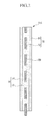
- FIG. 1 is a schematic diagram showing a rechargeable lithium battery according to one embodiment
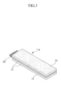
- FIG. 2 is a schematic diagram showing a positive electrode according to one embodiment
- FIG. 3 is a cross-sectional view showing the positive electrode shown in FIG. 2 .
- the rechargeable lithium battery 100 includes a battery cell including a positive electrode 114, a negative electrode 112 facing the positive electrode 114, a separator 113 interposed between the positive electrode 114 negative electrode 112 and, an electrolyte (not shown) impregnating the positive electrode 114, negative electrode 112, and separator 113, a battery case 120, and a sealing member 140 sealing the battery case 120.
- a positive electrode 114 is described referring to FIG. 2 and FIG. 3 .
- the positive electrode 114 includes a current collector 20 and positive electrode composition layers 16 provided on the both surfaces of the current collector 20.
- the current collector 20 may be a mesh-type and may be made of metal such as aluminum (Al).
- Al aluminum
- the adhesive property of positive electrode composition layers 16 disposed on the both surfaces of the current collector 20 may be increased to prevent the positive electrode composition layers 16 from separating from the current collector 20 or cracking on a surface of the electrodes, so as to improve the battery performance.
- the positive electrode composition layer 16 includes first positive electrode composition layers 12 disposed on the both surfaces of current collector 20 and second positive electrode composition layers 14 disposed on the outer surface of the first positive electrode composition layers 12.
- the number of the first positive electrode composition layer 12 and the second positive electrode composition layer 14 is not limited thereto, but the first positive electrode composition layer 12 and the second positive electrode composition layer 14 may be provided on either one surface of current collector 20 or more than two of the first positive electrode composition layer 12 and the second composition layer 14 may be formed on the current collector 20 as its center.
- Each of the first positive electrode composition layer 12 and the second positive electrode composition layer 14 includes a positive active material, a binder, and a conductive material.
- the first positive electrode composition layer 12 and the second positive electrode composition layer 14 have different component ratio of a positive active material, a binder, and a conductive material.
- the first positive electrode composition layer 12 disposed closer on the current collector 20 has higher amount of conductive material than that of the second positive electrode composition layer 14.
- the amount of the conductive material is increased in the first positive electrode composition layer 12 disposed closer on the current collector 20, it is possible to prevent from interrupting the electric charge transfer to the current collector 20, so as to ensure the conductivity even when the positive electrode composition layer 16 is formed in thicker to improve the battery performance.
- the second positive electrode composition layer 14 spacing from the current collector 20 has relatively low amount of conductive material to secure the enough amount of positive active material.
- the first positive electrode composition layer 12 includes a higher amount of conductive material than that of positive active material.
- the first positive electrode composition layer 12 may include, for example, about 20 to 35wt% of positive active material, about 40 to 60wt% of conductive material, and about 5 to 40wt% of binder.
- the second positive electrode composition layer 14 includes a higher amount of positive active material than that of conductive material.
- the second positive electrode composition layer 14 may include about 80 to 95 wt% of positive active material, about 1 to 10 wt% of conductive material, and about 4 to 10 wt% of binder.
- the first positive electrode composition layer 12 may have a thickness of about 5 ⁇ m to about 200 ⁇ m; the second positive electrode composition layer 14 may have a thickness of about 100 ⁇ m to about 500 ⁇ m.
- the entire thickness of positive electrode 114 may be thicker than about 300 ⁇ m, and may range from about 300 ⁇ m to about 1200 ⁇ m. Thereby, it is possible to provide a high capacity battery by including a positive electrode 114 having a thickness of more than 300 ⁇ m.
- the positive electrode 114 may have an average porosity of 30% or more.
- the average porosity stands for the total volume ratio of inside pores of positive electrode and may be measured by Mercury porosimetry.
- the average porosity may be controlled by pressing rate of positive electrode. When it is more than 30%, the impregnation region of electrolyte is increased to facilitate the oxidation and reduction reaction of lithium in electrode, so as to ensure the stable life-cycle characteristic for a long time.
- the average porosity is beneficial to be between about 30% and about 50% in order to ensure high efficient charge and discharge characteristics, to ensure the oxidation and reduction reaction of lithium and the stable cycle-life characteristics, and to maintain the stable electric network between positive active materials.
- the usable positive active material, binder and conductive material are as follows:
- A is selected from the group consisting of Ni, Co, Mn, and combinations thereof; D is selected from the group consisting of Al, Ni, Co, Mn, Cr, Fe, Mg, Sr, V, a rare earth element, and combinations thereof; E is selected from the group consisting of O, F, S, P, and combinations thereof; G is selected from the group consisting of Co, Mn, and combinations thereof; J is selected from the group consisting of F, S, P, and combinations thereof; L is is selected from the group consisting of Al, Cr, Mn, Fe, Mg, La, Ce, Sr, V, and combinations thereof; Q is selected from the group consisting of Ti, Mo, Mn, and combinations thereof; R is selected from the group consisting of Cr, V, Fe, Sc, Y, and combinations thereof; and Z is selected from the group consisting of V, Cr, Mn, Co, Ni, Cu, and combinations thereof.
- the binder improves binding properties of the positive active material particles to one another, and also with a current collector. Any material may be used for the binder without limitation if it does not causes a chemical change and improves adhesive property.
- the binder include polyvinyl alcohol, carboxylmethyl cellulose, hydroxypropyl cellulose, diacetyl cellulose, polyvinyl chloride, carboxylated polyvinyl chloride, polyvinyl difluoride, an ethylene oxide-containing polymer, polyvinyl pyrrolidone, polyurethane, polytetrafluoroethylene, polyvinylidene fluoride, polyethylene, polypropylene, styrene-butadiene rubber, acrylated styrene-butadiene rubber, an epoxy resin, and nylon.
- the polyvinylidene fluoride hexafluoropropylene may be preferable.
- hexafluoropropylene (HFP) is present in an amount of about 4 to about 20 wt% in the P(VdF-HFP), positive active material adherence may be improved.
- the conductive material is included to improve electrode conductivity. Any electrically conductive material may be used as a conductive material unless it causes a chemical change. Examples of the conductive material include polyphenylene derivatives, natural graphite, artificial graphite, carbon black, acetylene black, ketjen black, carbon fiber, and metal powders and metal fiber including copper, nickel, aluminum silver, and the like.
- a positive active material LiCoO 2 , LiMn 2 O 4 , LiFePO 4 , and combinations thereof may be preferably selected
- a binder polyvinylidene fluoride hexafluoro propylene (P(VdF-HFP) may be used, and for a conductive material acetyleneblack, ketjenblack, carbon fiber and combinations thereof may be preferably selected.
- the negative electrode 112 includes a current collector and a negative active material layer positioned on the current collector.
- the current collector may include a copper foil, a nickel foil, a stainless steel foil, a titanium foil, a nickel foil, a polymer substrate coated with conductive metals, and a metal net such as a metal mesh, but is not limited thereto.
- the negative active material layer includes a negative active material, a conductive material, and a binder.
- a material that reversibly intercalates/deintercalates lithium ions, lithium, lithium alloy, a material being capable of alloying with lithium, materials being doping and dedoping lithium, transition metal oxide, or combinations thereof may be used.
- the material that reversibly intercalates/deintercalates lithium ions includes carbon-based negative active materials.
- the carbon-based negative active materials may be selected from crystalline carbon, amorphous carbon, or combination thereof.
- the crystalline carbon may be non-shaped, or sheet, flake, spherical, or fiber shaped natural graphite or artificial graphite.
- the amorphous carbon may be a soft carbon (carbon obtained through sintering at a low temperature), a hard carbon (carbon obtained through sintering at a high temperature), mesophase pitch carbide, fired coke, and so on.
- the materials being capable of alloying with lithium includes an element selected from the group consisting of Na, K, Rb, Cs, Fr, Be, Mg, Ca, Sr, Ba, Ra, Ti, Ag, Zn, Cd, Al, Ga, In, Si, Ge, Sn, Pb, Sb, Bi, and combinations thereof.
- transition elements oxide examples include one selected from the group consisting of vanadium oxide, lithium vanadium oxide, Si, SiO x (0 ⁇ x ⁇ 2), Sn, SnO 2 , composite tin alloys, and combinations thereof.
- the conductive material and binder are the same as in described above.
- the separator 113 may be a single layer or multilayer, for example made of polyethylene, polypropylene, polyvinylidene fluoride, or combinations thereof.
- the electrolyte includes a non-aqueous organic solvent and a lithium salt.
- the non-aqueous organic solvent acts as a medium for transmitting lithium ions
- examples of the organic solvent include one selected from the group consisting of carbonate-based, ester-based, ether-based, ketone-based, alcohol-based, or aprotic solvents.
- Non-limiting examples of the carbonate-based solvents includes dimethyl carbonate (DMC), diethyl carbonate (DEC), dipropyl carbonate (DPC), methylpropyl carbonate (MPC), ethylpropyl carbonate (EPC), methylethyl carbonate (MEC), ethylmethyl carbonate (EMC), ethylene carbonate (EC), propylene carbonate (PC), butylene carbonate (BC), and the like.
- DMC dimethyl carbonate
- DEC diethyl carbonate
- DPC dipropyl carbonate
- MPC methylpropyl carbonate
- EPC ethylpropyl carbonate
- MEC methylethyl carbonate
- EMC ethylmethyl carbonate
- EMC ethylene carbonate
- PC propylene carbonate
- BC butylene carbonate
- linear carbonate compounds and cyclic carbonate compounds When the linear carbonate compounds and cyclic carbonate compounds are mixed, an organic solvent having high dielectric constant and low viscosity can be provided.
- the cyclic carbonate compounds and linear carbonate compounds may be mixed together at a volume ratio of about 1:1 to about 1:9.
- Non-limiting examples of the ester-based solvent include methylacetate, ethylacetate, n-propylacetate, dimethylacetate, methylpropinonate, ethylpropinonate, ⁇ -butyrolactone, decanolide, valerolactone, mevalonolactone, caprolactone, and the like.
- Non-limiting examples of the ether-based solvent include dibutylether, tetraglyme, diglyme, dimethoxyethane, 2-methyltetrahydrofuran, tetrahydrofuran, and the like
- non-limiting examples of the ketone-based solvent include cyclohexanone, and the like.
- Non-limiting examples of the alcohol-based solvent include ethanol, isopropyl alcohol, and the like.
- the non-aqueous organic solvent may be used singularly or in a composition.
- a composition ratio can be controlled in accordance with a desirable battery performance.
- the non-aqueous electrolyte may further include overcharge inhibitor additives such as ethylene carbonate, pyrocarbonate, and the like.
- FIG. 4 is a schematic diagram showing a method of manufacturing a positive electrode for a rechargeable lithium battery according to one embodiment.
- first positive electrode composition and a second positive electrode composition in which each includes a positive active material, a binder, and a conductive material and has the different amount of conductive material.
- the first positive electrode composition may include a higher amount of conductive material than that of positive active material, for example, it may include about 20 to 35wt% of positive active material, about 40 to 60wt% of conductive material, and about 5 to 40wt% of binder.
- the second positive electrode composition includes the higher amount of positive active material than that of conductive material, for example, it may include about 80 to 95wt% of positive active material, about 1 to 10wt% of conductive material, and about 4 to 10wt% of binder.
- the first positive electrode composition and the second positive electrode composition may be prepared in a form of slurry.
- the first positive electrode composition is coated on both surfaces of the current collector 20 having a mesh type to form a first positive electrode composition layer (12).
- the coating may be carried out, for example, by spraying or dipping.
- the second positive electrode composition is coated on an inorganic plate, such as glass, or an organic plate, such as polymer (not shown), to provide a second positive electrode composition layer 14.
- the second positive electrode composition layers 14 are disposed on both surfaces of the current collector 20 that the first positive electrode composition layer 12 are coated on.
- the number of the first positive electrode composition layer 12 and the second positive electrode composition layer 14 is not limited thereto, and the first positive electrode composition layer 12 and the second positive electrode composition layer 14 may be disposed only one surface of current collector 20, or they may be disposed on the current collector 20 in more numbers in the center of current collector 20.
- the current collector 20, the first positive electrode composition layer 12, and the second positive electrode composition layer 14 are pressed from top and bottom with a compressor 50 such as a roller at a predetermined temperature.
- the pressing may be performed with thermal pressing at a temperature of about 150 to 170°C, and may be performed for two or more times, if required.
- the positive electrode composition layer is disposed at least one surface of the current collector and pressed from top and bottom at the same time, it is possible to prevent cracking by the difference between the dry speed of solvent in the positive electrode composition layer contacting to the current collector and that in the positive electrode composition layer contacting to air. Furthermore, it is possible to decrease the thickness of current collector by using a mesh-typed current collector and to improve the adhesive property between positive electrode composition layers, so as to improve the battery performance.
Abstract
Description
- This disclosure relates to an electrode for a rechargeable lithium battery, a method of manufacturing the same, and a rechargeable lithium battery including the electrode.
- Batteries transform chemical energy generated from an electrochemical oxidation-reduction reaction of chemical materials inside the battery into electrical energy. The batteries are divided into primary batteries, which should be discarded after the energy inside the batteries is all consumed, and rechargeable batteries, which can be recharged several times.
- Among the batteries, the rechargeable battery may be charged/ discharged several times through reversible transformation between chemical energy and electrical energy.
- Meanwhile, recent development in high-end electronic industries makes electronic devices smaller and lighter and this leads to an increase in portable electronic devices.
- Since the portable electronic devices demands for batteries with high energy density, researchers are studying vigorously to develop rechargeable lithium battery.
- The rechargeable lithium battery is fabricated by injecting electrolyte into a battery cell, which includes a positive electrode including a positive active material capable of intercalating/deintercalating lithium ions and a negative electrode including a negative active material capable of interclating/deintercalating lithium ions.
- In order to realize large capacity batteries, positive and negative electrodes need to be formed thickly. However, when the electrodes are formed thickly, electrode conductivity may be degraded and may have a bad effect on rechargeable battery performance.
- An exemplary embodiment of the present invention provides an electrode for a rechargeable lithium battery, a method of manufacturing the same, and rechargeable lithium battery including the electrode.
- According to one aspect of the present invention, an electrode for a rechargeable lithium battery comprises: a current collector; a first electrode composition layer provided on a surface of the current collector; and a second electrode composition layer provided on the first composition layer, wherein each of the first electrode composition layer and the second electrode composition layer includes an active material, a conductive material, and a binder, and wherein the first electrode composition layer includes a higher amount of conductive material than the second electrode composition layer.
- According to another aspect of the present invention, a method of manufacturing an electrode for a rechargeable lithium battery comprises: providing a first electrode composition and a second electrode composition, each including a active material, a binder, and a conductive material, wherein the first electrode composition includes a higher amount of conductive material; forming a first electrode composition layer including the first electrode composition and a second electrode composition layer including the second electrode composition; disposing the first electrode composition layer on a surface of a current collector and disposing the second electrode composition layer on the first electrode composition layer and pressing the current collector, the first electrode composition layer, and the second electrode composition layer.
- According to another aspect of the present invention, a rechargeable lithium battery is provided that comprises a first electrode in accordance with the invention as defined above, a second electrode, a separator interposed between the first electrode and the second electrode, and a electrolyte.
- The second electrode composition layer may include a higher amount of active material than the first electrode composition layer.
- The first electrode composition layer may have a higher amount of the conductive material than of the active material.
- The conductive material of the first electrode composition layer may be included in about 40 to 60 wt%, and the active material of the first positive composition layer may be included in about 20 to 35 wt%.
- The second electrode composition layer may include the active material in a higher amount than that of the conductive material.
- The active material of the second electrode composition layer may be included in about 80 to 95 wt%, and the conductive material of the second electrode composition layer may be included in about 1 to 10 wt%.
- The current collector may be porous, and more specifically may be a conductive mesh.
- The first electrode composition layer may have a thickness of about 5 to about 200µm, and the second electrode composition layer may have a thickness of about 100 to about 500µm.
- The total thickness of the electrode may be thicker than about 300µm.
- An average porosity of the electrode may be about 30% or more.
- The current collector may be planar and have two opposed surfaces, and the first electrode composition layer and the second composition layer are provided on both surfaces of the current collector.
- The electrode may be a positive electrode, wherein the first and second electrode composition layers are first and second positive electrode composition layers.
- In the method of manufacturing the electrode for a rechargeable lithium battery, the current collector may have two opposed surfaces, and the first and second composition layer may be provided on both surfaces. The step of pressing the current collector, the first positive electrode composition layer, and the second positive electrode composition layer may include thermal pressing from both sides of the current collector. The thermal pressing may be carried out at a temperature from 150 to 170°C.
- As in above, it is possible to provide a battery with high capacity and high efficiency characteristics as well as to provide the electrode with the high conductivity by the means of including a plurality of electrode composition layers in which each has the different amounts of active material and conductive material.
- Exemplary embodiments of the present invention will be described more fully hereinafter with reference to the accompanying drawings, in which:
-
FIG. 1 is a schematic diagram showing a rechargeable lithium battery according to one embodiment of the present invention. -
FIG. 2 is a schematic diagram showing a positive electrode according to one embodiment of the present invention. -
FIG. 3 is a cross-sectional view showing the positive electrode shown inFIG. 2 . -
FIG. 4 is a schematic diagram showing a method of manufacturing a positive electrode for a rechargeable lithium battery according to one embodiment of the present invention. - The present invention may, however, be embodied in many different forms and should not be construed as limited to the exemplary embodiments set forth herein. In the drawings, the thickness of layers, films, panels, regions, etc., are exaggerated for clarity. Like reference numerals designate like elements throughout the specification.
- It will be understood that when an element such as a layer, film, region, or substrate is referred to as being "on" another element, it can be directly on the other element or intervening elements may also be present. In contrast, when an element is referred to as being "directly on" another element, there are no intervening elements present.
- The positive electrode according to one embodiment and the rechargeable lithium battery including the same will be described with reference to
FIG. 1 to FIG. 3 . However, the invention may also be applied to a negative electrode. -
FIG. 1 is a schematic diagram showing a rechargeable lithium battery according to one embodiment;FIG. 2 is a schematic diagram showing a positive electrode according to one embodiment;FIG. 3 is a cross-sectional view showing the positive electrode shown inFIG. 2 . - Referring to
FIG. 1 , therechargeable lithium battery 100 includes a battery cell including apositive electrode 114, anegative electrode 112 facing thepositive electrode 114, aseparator 113 interposed between thepositive electrode 114negative electrode 112 and, an electrolyte (not shown) impregnating thepositive electrode 114,negative electrode 112, andseparator 113, abattery case 120, and asealing member 140 sealing thebattery case 120. - Firstly, a
positive electrode 114 is described referring toFIG. 2 andFIG. 3 . - Referring to
FIG. 2 andFIG. 3 , thepositive electrode 114 includes acurrent collector 20 and positiveelectrode composition layers 16 provided on the both surfaces of thecurrent collector 20. - The
current collector 20 may be a mesh-type and may be made of metal such as aluminum (Al). When thecurrent collector 20 is a mesh-type, it is possible to decrease the thickness of current collector, so as to decrease the entire thickness of positive electrode. In addition, the adhesive property of positiveelectrode composition layers 16 disposed on the both surfaces of thecurrent collector 20 may be increased to prevent the positiveelectrode composition layers 16 from separating from thecurrent collector 20 or cracking on a surface of the electrodes, so as to improve the battery performance. - The positive
electrode composition layer 16 includes first positiveelectrode composition layers 12 disposed on the both surfaces ofcurrent collector 20 and second positiveelectrode composition layers 14 disposed on the outer surface of the first positiveelectrode composition layers 12. However, the number of the first positiveelectrode composition layer 12 and the second positiveelectrode composition layer 14 is not limited thereto, but the first positiveelectrode composition layer 12 and the second positiveelectrode composition layer 14 may be provided on either one surface ofcurrent collector 20 or more than two of the first positiveelectrode composition layer 12 and thesecond composition layer 14 may be formed on thecurrent collector 20 as its center. - Each of the first positive
electrode composition layer 12 and the second positiveelectrode composition layer 14 includes a positive active material, a binder, and a conductive material. The first positiveelectrode composition layer 12 and the second positiveelectrode composition layer 14 have different component ratio of a positive active material, a binder, and a conductive material. - Specifically, the first positive
electrode composition layer 12 disposed closer on thecurrent collector 20 has higher amount of conductive material than that of the second positiveelectrode composition layer 14. When the amount of the conductive material is increased in the first positiveelectrode composition layer 12 disposed closer on thecurrent collector 20, it is possible to prevent from interrupting the electric charge transfer to thecurrent collector 20, so as to ensure the conductivity even when the positiveelectrode composition layer 16 is formed in thicker to improve the battery performance. On the other hand, the second positiveelectrode composition layer 14 spacing from thecurrent collector 20 has relatively low amount of conductive material to secure the enough amount of positive active material. - Furthermore, the first positive
electrode composition layer 12 includes a higher amount of conductive material than that of positive active material. The first positiveelectrode composition layer 12 may include, for example, about 20 to 35wt% of positive active material, about 40 to 60wt% of conductive material, and about 5 to 40wt% of binder. - The second positive
electrode composition layer 14 includes a higher amount of positive active material than that of conductive material. For example, the second positiveelectrode composition layer 14 may include about 80 to 95 wt% of positive active material, about 1 to 10 wt% of conductive material, and about 4 to 10 wt% of binder. - The first positive
electrode composition layer 12 may have a thickness of about 5µm to about 200µm; the second positiveelectrode composition layer 14 may have a thickness of about 100µm to about 500µm. - The entire thickness of
positive electrode 114 may be thicker than about 300µm, and may range from about 300µm to about 1200µm. Thereby, it is possible to provide a high capacity battery by including apositive electrode 114 having a thickness of more than 300µm. - In addition, the
positive electrode 114 may have an average porosity of 30% or more. The average porosity stands for the total volume ratio of inside pores of positive electrode and may be measured by Mercury porosimetry. The average porosity may be controlled by pressing rate of positive electrode. When it is more than 30%, the impregnation region of electrolyte is increased to facilitate the oxidation and reduction reaction of lithium in electrode, so as to ensure the stable life-cycle characteristic for a long time. - On the other hand, the average porosity is beneficial to be between about 30% and about 50% in order to ensure high efficient charge and discharge characteristics, to ensure the oxidation and reduction reaction of lithium and the stable cycle-life characteristics, and to maintain the stable electric network between positive active materials.
- The usable positive active material, binder and conductive material are as follows:
- For the positive active material, compounds being capable of reversibly intercalating and deintercalating lithium ions may be used without limitation. Examples of the positive active material may include composite oxide including lithium (Li) and a metal selected from the group consisting of cobalt (Co), manganese (Mn), nickel (Ni), and combinations thereof as follows:
- LiaA1-bDbE2 wherein, in the above formula, 0.90 ≤ a ≤ 1.8, and 0 ≤ b ≤ 0.5; LiaG1-bDbO2-cJc wherein, in the above formula, 0.90 ≤ a ≤ 1.8, 0 ≤ b ≤ 0.5, and 0 ≤ c ≤ 0.05; LiG2-bDbO4-cJc wherein, in the above formula, 0 ≤ b ≤ 0.5, and 0 ≤ c ≤ 0.05; LiaNi1-b-cCobDcEα wherein, in the above formula, 0.90 ≤ a ≤ 1.8, 0 ≤ b ≤ 0.5, 0 ≤ c ≤ 0.05, and 0 < α ≤ 2; LiaNi1-b-cCobDcO2-αJα wherein, in the above formula, 0.90 ≤ a ≤ 1.8, 0 ≤ b ≤ 0.5, 0 ≤ c ≤ 0.05, and 0 < α < 2; LiaNi1-b-cCobDcO2-αJ2 wherein, in the above formula, 0.90 ≤ a ≤ 1.8, 0 ≤ b ≤ 0.5, 0 ≤ c ≤ 0.05, and 0 < α < 2); LiaNi1-b-cMnbDcEα wherein, in the above formula, 0.90 ≤ a ≤ 1.8, 0 ≤ b ≤ 0.5, 0 ≤ c ≤ 0.05, and 0 < α ≤ 2; LiaNi1-b-cMnbDcO2-αJα wherein, in the above formula, 0.90 ≤ a ≤ 1.8, 0 ≤ b ≤ 0.5, 0 ≤ c ≤ 0.05, and 0 < α < 2; LiaNi1-b-cMnbDcO2-αJ2 wherein, in the above formula, 0.90 ≤ a ≤ 1.8, 0 ≤ b ≤ 0.5, 0 ≤ c ≤ 0.05, and 0 < α < 2; LiaNibGcLdO2 wherein, in the above formula, 0.90 ≤ a ≤ 1.8, 0 ≤ b ≤ 0.9, 0 ≤ c ≤ 0.5, and 0.001 ≤ d ≤ 0.1; LiaNibCocMndLeO2 wherein, in the above formula, 0.90 ≤ a ≤ 1.8, 0 ≤ b ≤ 0.9, 0 ≤ c ≤ 0.5, 0 ≤ d ≤0.5, and 0.001 ≤ e ≤ 0.1; LiaNiLbO2 wherein, in the above formula, 0.90 ≤ a ≤ 1.8, and 0.001 ≤ b ≤ 0.1; LiaCoLbO2 wherein, in the above formula, 0.90 ≤ a ≤ 1.8, and 0.001 ≤ b ≤ 0.1; LiaMnLbO2 wherein, in the above formula, 0.90 ≤ a ≤ 1.8, and 0.001 ≤ b ≤ 0.1; LiaMn2LbO4 wherein, in the above formula, 0.90 ≤ a ≤ 1.8, and 0.001 ≤ b ≤ 0.1; QO2; QS2; LiQS2; V2O5; LiV2O5; LiRO2; LiNiVO4; Li(3f)Z2(PO4)3(0 ≤ f ≤ 2); Li(3-f)Fe2(PO4)3(0 ≤ f ≤ 2); and LiFePO4.
- In the above formulas, A is selected from the group consisting of Ni, Co, Mn, and combinations thereof; D is selected from the group consisting of Al, Ni, Co, Mn, Cr, Fe, Mg, Sr, V, a rare earth element, and combinations thereof; E is selected from the group consisting of O, F, S, P, and combinations thereof; G is selected from the group consisting of Co, Mn, and combinations thereof; J is selected from the group consisting of F, S, P, and combinations thereof; L is is selected from the group consisting of Al, Cr, Mn, Fe, Mg, La, Ce, Sr, V, and combinations thereof; Q is selected from the group consisting of Ti, Mo, Mn, and combinations thereof; R is selected from the group consisting of Cr, V, Fe, Sc, Y, and combinations thereof; and Z is selected from the group consisting of V, Cr, Mn, Co, Ni, Cu, and combinations thereof.
- The binder improves binding properties of the positive active material particles to one another, and also with a current collector. Any material may be used for the binder without limitation if it does not causes a chemical change and improves adhesive property. Examples of the binder include polyvinyl alcohol, carboxylmethyl cellulose, hydroxypropyl cellulose, diacetyl cellulose, polyvinyl chloride, carboxylated polyvinyl chloride, polyvinyl difluoride, an ethylene oxide-containing polymer, polyvinyl pyrrolidone, polyurethane, polytetrafluoroethylene, polyvinylidene fluoride, polyethylene, polypropylene, styrene-butadiene rubber, acrylated styrene-butadiene rubber, an epoxy resin, and nylon. In one embodiment, the polyvinylidene fluoride hexafluoropropylene (P(VdF-HFP)) may be preferable. When hexafluoropropylene (HFP) is present in an amount of about 4 to about 20 wt% in the P(VdF-HFP), positive active material adherence may be improved.
- The conductive material is included to improve electrode conductivity. Any electrically conductive material may be used as a conductive material unless it causes a chemical change. Examples of the conductive material include polyphenylene derivatives, natural graphite, artificial graphite, carbon black, acetylene black, ketjen black, carbon fiber, and metal powders and metal fiber including copper, nickel, aluminum silver, and the like.
- In one embodiment, for a positive active material LiCoO2, LiMn2O4, LiFePO4, and combinations thereof may be preferably selected, for a binder polyvinylidene fluoride hexafluoro propylene (P(VdF-HFP) may be used, and for a conductive material acetyleneblack, ketjenblack, carbon fiber and combinations thereof may be preferably selected.
- The
negative electrode 112 includes a current collector and a negative active material layer positioned on the current collector. - The current collector may include a copper foil, a nickel foil, a stainless steel foil, a titanium foil, a nickel foil, a polymer substrate coated with conductive metals, and a metal net such as a metal mesh, but is not limited thereto.
- The negative active material layer includes a negative active material, a conductive material, and a binder.
- For the negative active material, a material that reversibly intercalates/deintercalates lithium ions, lithium, lithium alloy, a material being capable of alloying with lithium, materials being doping and dedoping lithium, transition metal oxide, or combinations thereof may be used. The material that reversibly intercalates/deintercalates lithium ions includes carbon-based negative active materials.
- The carbon-based negative active materials may be selected from crystalline carbon, amorphous carbon, or combination thereof. The crystalline carbon may be non-shaped, or sheet, flake, spherical, or fiber shaped natural graphite or artificial graphite. The amorphous carbon may be a soft carbon (carbon obtained through sintering at a low temperature), a hard carbon (carbon obtained through sintering at a high temperature), mesophase pitch carbide, fired coke, and so on.
- The materials being capable of alloying with lithium includes an element selected from the group consisting of Na, K, Rb, Cs, Fr, Be, Mg, Ca, Sr, Ba, Ra, Ti, Ag, Zn, Cd, Al, Ga, In, Si, Ge, Sn, Pb, Sb, Bi, and combinations thereof.
- Examples of the transition elements oxide, compounds being doping and dedoping lithium, or compounds being capable of reversibly reacting lithium include one selected from the group consisting of vanadium oxide, lithium vanadium oxide, Si, SiOx (0<x<2), Sn, SnO2, composite tin alloys, and combinations thereof.
- The conductive material and binder are the same as in described above.
- The
separator 113 may be a single layer or multilayer, for example made of polyethylene, polypropylene, polyvinylidene fluoride, or combinations thereof. - The electrolyte includes a non-aqueous organic solvent and a lithium salt.
- The non-aqueous organic solvent acts as a medium for transmitting lithium ions, and examples of the organic solvent include one selected from the group consisting of carbonate-based, ester-based, ether-based, ketone-based, alcohol-based, or aprotic solvents.
- Non-limiting examples of the carbonate-based solvents includes dimethyl carbonate (DMC), diethyl carbonate (DEC), dipropyl carbonate (DPC), methylpropyl carbonate (MPC), ethylpropyl carbonate (EPC), methylethyl carbonate (MEC), ethylmethyl carbonate (EMC), ethylene carbonate (EC), propylene carbonate (PC), butylene carbonate (BC), and the like.
- When the linear carbonate compounds and cyclic carbonate compounds are mixed, an organic solvent having high dielectric constant and low viscosity can be provided. The cyclic carbonate compounds and linear carbonate compounds may be mixed together at a volume ratio of about 1:1 to about 1:9.
- Non-limiting examples of the ester-based solvent include methylacetate, ethylacetate, n-propylacetate, dimethylacetate, methylpropinonate, ethylpropinonate, γ-butyrolactone, decanolide, valerolactone, mevalonolactone, caprolactone, and the like. Non-limiting examples of the ether-based solvent include dibutylether, tetraglyme, diglyme, dimethoxyethane, 2-methyltetrahydrofuran, tetrahydrofuran, and the like, and non-limiting examples of the ketone-based solvent include cyclohexanone, and the like. Non-limiting examples of the alcohol-based solvent include ethanol, isopropyl alcohol, and the like.
- The non-aqueous organic solvent may be used singularly or in a composition. When the organic solvent is used in a composition, a composition ratio can be controlled in accordance with a desirable battery performance.
- The non-aqueous electrolyte may further include overcharge inhibitor additives such as ethylene carbonate, pyrocarbonate, and the like.
- Hereinafter, a method of manufacturing a positive electrode for a rechargeable lithium battery according to another embodiment is described with reference to
FIG. 4 together withFIG. 1 to 3 . -
FIG. 4 is a schematic diagram showing a method of manufacturing a positive electrode for a rechargeable lithium battery according to one embodiment. - Firstly, it prepares a first positive electrode composition and a second positive electrode composition in which each includes a positive active material, a binder, and a conductive material and has the different amount of conductive material.
- The first positive electrode composition may include a higher amount of conductive material than that of positive active material, for example, it may include about 20 to 35wt% of positive active material, about 40 to 60wt% of conductive material, and about 5 to 40wt% of binder.
- The second positive electrode composition includes the higher amount of positive active material than that of conductive material, for example, it may include about 80 to 95wt% of positive active material, about 1 to 10wt% of conductive material, and about 4 to 10wt% of binder.
- The first positive electrode composition and the second positive electrode composition may be prepared in a form of slurry. In one embodiment, as shown in
FIG. 4 (a) , the first positive electrode composition is coated on both surfaces of thecurrent collector 20 having a mesh type to form a first positive electrode composition layer (12). The coating may be carried out, for example, by spraying or dipping. In one embodiment, the second positive electrode composition is coated on an inorganic plate, such as glass, or an organic plate, such as polymer (not shown), to provide a second positiveelectrode composition layer 14. - Then, referring to
FIG. 4 (b) , the second positive electrode composition layers 14 are disposed on both surfaces of thecurrent collector 20 that the first positiveelectrode composition layer 12 are coated on. However, the number of the first positiveelectrode composition layer 12 and the second positiveelectrode composition layer 14 is not limited thereto, and the first positiveelectrode composition layer 12 and the second positiveelectrode composition layer 14 may be disposed only one surface ofcurrent collector 20, or they may be disposed on thecurrent collector 20 in more numbers in the center ofcurrent collector 20. - Then, referring to
FIG. 4 (c) , thecurrent collector 20, the first positiveelectrode composition layer 12, and the second positiveelectrode composition layer 14 are pressed from top and bottom with acompressor 50 such as a roller at a predetermined temperature. The pressing may be performed with thermal pressing at a temperature of about 150 to 170°C, and may be performed for two or more times, if required. - When the positive electrode composition layer is disposed at least one surface of the current collector and pressed from top and bottom at the same time, it is possible to prevent cracking by the difference between the dry speed of solvent in the positive electrode composition layer contacting to the current collector and that in the positive electrode composition layer contacting to air. Furthermore, it is possible to decrease the thickness of current collector by using a mesh-typed current collector and to improve the adhesive property between positive electrode composition layers, so as to improve the battery performance.
- While this invention has been described in connection with what is presently considered to be practical exemplary embodiments, it is to be understood that the invention is not limited to the disclosed embodiments, but, on the contrary, is intended to cover various modifications and equivalent arrangements included within the scope of the appended claims.
Claims (19)
- An electrode for a rechargeable lithium battery comprising:a current collector (20);a first electrode composition layer (12) provided on a surface of the current collector (20); anda second electrode composition layer (14) provided on the first composition layer (12),wherein each of the first electrode composition layer (12) and the second electrode composition layer (14) includes an active material, a conductive material, and a binder, and wherein the first electrode composition layer (12) includes a higher amount of conductive material than the second electrode composition layer (14).
- The electrode of claim 1, wherein the second electrode composition layer (14) includes a higher amount of active material than the first electrode composition layer (12).
- The electrode of claim 1 or 2, wherein the first electrode composition layer (12) comprises a higher amount of the conductive material than of the active material.
- The electrode of claim 3, wherein the first electrode composition layer (12) comprises about 40 to 60 wt% of conductive material, and about 20 to 35 wt% of the active material.
- The electrode of any one of the preceding claims, wherein the second electrode composition layer (14) comprises a higher amount of the active material than of the conductive material.
- The electrode of claim 5, wherein the second electrode composition layer (14) comprises about 1 to 10 wt% of conductive material, and about 80 to 95 wt% of the active material.
- The electrode of any one of the preceding claims, wherein the current collector (20) is porous.
- The electrode of any one of the preceding claims, wherein the current collector (20) is a conductive mesh.
- The electrode of any one of the preceding claims, wherein the first electrode composition layer (12) has a thickness of about 5 to about 200µm, and the second electrode composition layer (14) has a thickness of about 100 to about 500µm.
- The electrode of any one of the preceding claims, wherein the total thickness of the electrode is thicker than about 300µm.
- The electrode of any one of the preceding claims, wherein the average porosity of the electrode is about 30% or more.
- The electrode of any one of the preceding claims, wherein the current collector (20) is planar, having two opposed surfaces, and the first electrode composition layer (12) and the second composition layer (14) are provided on both surfaces of the current collector (20).
- The electrode of any one of the preceding claims, wherein the electrode is a positive electrode, wherein the first and second electrode composition layers are first and second positive electrode composition layers.
- A rechargeable lithium battery comprising a first electrode (114) according to any one of the preceding claims, a second electrode (112), a separator (113) interposed between the first electrode (114) and the second electrode (112), and an electrolyte.
- A method of manufacturing an electrode for a rechargeable lithium battery comprises:providing a first electrode composition and a second electrode composition, each including a active material, a binder, and a conductive material, wherein the first electrode composition includes a higher amount of conductive material;forming a first electrode composition layer (12) including the first electrode composition and a second electrode composition layer (14) including the second electrode composition;disposing the first electrode composition layer (12) on a surface of a current collector (20) and disposing the second electrode composition layer (14) on the first electrode composition layer (12); andpressing the current collector (20), the first electrode composition layer (12), and the second electrode composition layer (14).
- The method of claim 15, wherein the current collector (20) has two opposed surfaces, and the first electrode composition layer (12) and the second composition layer (14) are provided on both surfaces of the current collector (20).
- The method of claim 15 or 16, wherein the step of pressing the current collector (20), the first electrode composition layer (12), and the second electrode composition layer (14) comprises thermal pressing from both sides of the current collector (20).
- The method of claim 17, wherein the thermal pressing is carried out at a temperature of between 150°C and 170°C.
- The method of any one of claims 15 to 18, wherein the electrode is a positive electrode, wherein the first and second electrode composition layers are first and second positive electrode composition layers.
Applications Claiming Priority (2)
| Application Number | Priority Date | Filing Date | Title |
|---|---|---|---|
| US17684709P | 2009-05-08 | 2009-05-08 | |
| US12/575,419 US9083055B2 (en) | 2009-05-08 | 2009-10-07 | Electrode with plural active material layers with different amounts of conductive material for rechargeable lithium battery and method for manufacturing the same and rechargeable lithium battery including the electrode |
Publications (2)
| Publication Number | Publication Date |
|---|---|
| EP2249418A1 true EP2249418A1 (en) | 2010-11-10 |
| EP2249418B1 EP2249418B1 (en) | 2012-08-22 |
Family
ID=42542965
Family Applications (1)
| Application Number | Title | Priority Date | Filing Date |
|---|---|---|---|
| EP10162265A Not-in-force EP2249418B1 (en) | 2009-05-08 | 2010-05-07 | Electrode for rechargeable lithium battery and method for manufacturing the same and rechargeable lithium battery including the electrode |
Country Status (5)
| Country | Link |
|---|---|
| US (1) | US9083055B2 (en) |
| EP (1) | EP2249418B1 (en) |
| JP (1) | JP2010262916A (en) |
| KR (1) | KR101223622B1 (en) |
| CN (1) | CN101882676A (en) |
Cited By (1)
| Publication number | Priority date | Publication date | Assignee | Title |
|---|---|---|---|---|
| CN104137306A (en) * | 2012-02-23 | 2014-11-05 | 丰田自动车株式会社 | Sealed nonaqueous electrolyte secondary battery |
Families Citing this family (28)
| Publication number | Priority date | Publication date | Assignee | Title |
|---|---|---|---|---|
| KR101274818B1 (en) | 2008-01-08 | 2013-06-13 | 주식회사 엘지화학 | Cathode for battery, method for manufacturing thereof, and lithium secondary battery comprising the same |
| US20120321947A1 (en) * | 2009-09-25 | 2012-12-20 | Satoshi Goto | Lithium secondary battery and manufacturing method for same |
| JP5323259B2 (en) * | 2010-05-28 | 2013-10-23 | パナソニック株式会社 | Positive electrode for non-aqueous electrolyte secondary battery and non-aqueous electrolyte secondary battery |
| KR101351902B1 (en) | 2011-06-02 | 2014-01-22 | 주식회사 엘지화학 | Anode For Secondary Battery And Secondary Battery Having The Same |
| DE202012013285U1 (en) | 2011-10-13 | 2015-12-14 | Lg Chem. Ltd. | Secondary battery of the cable type |
| WO2013055187A1 (en) | 2011-10-13 | 2013-04-18 | 주식회사 엘지화학 | Cable-type secondary battery |
| CN103875114B (en) | 2011-10-14 | 2017-03-29 | 株式会社Lg 化学 | Cable Type Rechargeable Battery |
| EP2772980B1 (en) | 2011-10-25 | 2018-01-10 | LG Chem, Ltd. | Cable-type secondary battery |
| KR101483686B1 (en) | 2011-11-02 | 2015-01-16 | 주식회사 엘지화학 | Cable-Type Secondary Battery |
| US20160126547A1 (en) * | 2012-11-13 | 2016-05-05 | Kazumichi Koga | Lithium manganate particles for non-aqueous electrolyte secondary batteries and process for producing the same, and non-aqueous electrolyte secondary battery |
| KR101517522B1 (en) | 2013-07-19 | 2015-05-06 | 가천대학교 산학협력단 | Anode Substrate, all solid state battery with high capacity, and methods for manufacturing the same |
| US10109856B2 (en) * | 2013-09-27 | 2018-10-23 | Sanyo Electric Co., Ltd. | Negative electrode for nonaqueous electrolyte secondary batteries |
| WO2015049775A1 (en) * | 2013-10-04 | 2015-04-09 | 株式会社日立製作所 | Positive electrode for lithium ion secondary batteries, lithium ion secondary battery using positive electrode for lithium ion secondary batteries, and method for producing positive electrode for lithium ion secondary batteries |
| KR101660111B1 (en) * | 2014-07-18 | 2016-09-26 | 주식회사 엘지화학 | Lithium secondary battery electrode and method for preparing the same |
| JP6156398B2 (en) | 2015-01-16 | 2017-07-05 | トヨタ自動車株式会社 | Non-aqueous electrolyte secondary battery manufacturing method and non-aqueous electrolyte secondary battery |
| JP2016143477A (en) * | 2015-01-30 | 2016-08-08 | セイコーエプソン株式会社 | Electrode complex, manufacturing method of electrode complex and battery |
| KR102023732B1 (en) * | 2015-07-29 | 2019-09-20 | 주식회사 엘지화학 | Electrode and electrochemical device including the same |
| KR102256302B1 (en) * | 2017-03-09 | 2021-05-26 | 삼성에스디아이 주식회사 | Electrode assembly and lithium battery including the same |
| JP2020501328A (en) * | 2017-06-23 | 2020-01-16 | エルジー・ケム・リミテッド | Positive electrode for lithium secondary battery and lithium secondary battery including the same |
| US11374212B2 (en) | 2017-06-27 | 2022-06-28 | Lg Energy Solution, Ltd. | Multilayer positive electrode for lithium secondary battery and method for manufacturing the same |
| US20200266418A1 (en) * | 2018-03-23 | 2020-08-20 | EnPower, Inc. | Gap section multilayer electrode profile |
| US10991942B2 (en) | 2018-03-23 | 2021-04-27 | EnPower, Inc. | Electrochemical cells having one or more multilayer electrodes |
| KR102537264B1 (en) * | 2019-07-26 | 2023-05-30 | 주식회사 엘지에너지솔루션 | Cathode material having improved thermal stability for lithium secondary battery and manufacturing method thereof |
| US10998553B1 (en) | 2019-10-31 | 2021-05-04 | EnPower, Inc. | Electrochemical cell with integrated ceramic separator |
| JPWO2022176796A1 (en) * | 2021-02-16 | 2022-08-25 | ||
| US11594784B2 (en) | 2021-07-28 | 2023-02-28 | EnPower, Inc. | Integrated fibrous separator |
| WO2023053626A1 (en) | 2021-09-28 | 2023-04-06 | 三洋電機株式会社 | Non-aqueous electrolyte secondary battery |
| KR20230161118A (en) | 2022-05-18 | 2023-11-27 | 에스케이온 주식회사 | Anode for lithium secondary battery and lithium secondary battery including the same |
Citations (2)
| Publication number | Priority date | Publication date | Assignee | Title |
|---|---|---|---|---|
| US20060099495A1 (en) * | 2004-11-08 | 2006-05-11 | Hiroyuki Suzuki | Cathode and battery |
| EP1953851A1 (en) * | 2005-11-10 | 2008-08-06 | Nissan Motor Co., Ltd. | Electrode for secondary battery and secondary battery using same |
Family Cites Families (7)
| Publication number | Priority date | Publication date | Assignee | Title |
|---|---|---|---|---|
| JPH09306471A (en) | 1996-05-16 | 1997-11-28 | Japan Storage Battery Co Ltd | Nonaqueous electrolyte secondary battery and manufacture thereof |
| US7615314B2 (en) * | 2004-12-10 | 2009-11-10 | Canon Kabushiki Kaisha | Electrode structure for lithium secondary battery and secondary battery having such electrode structure |
| JP4380579B2 (en) * | 2005-04-13 | 2009-12-09 | 宇部興産株式会社 | Non-aqueous secondary battery |
| JP2008034215A (en) | 2006-07-28 | 2008-02-14 | Hitachi Ltd | Lithium secondary battery, positive electrode therefor, and its manufacturing method |
| JP5348730B2 (en) | 2006-08-31 | 2013-11-20 | 日立マクセル株式会社 | Lithium ion secondary battery |
| JP5167703B2 (en) | 2007-06-20 | 2013-03-21 | 日産自動車株式会社 | Battery electrode |
| JP5523678B2 (en) | 2007-07-18 | 2014-06-18 | 日産自動車株式会社 | Non-aqueous electrolyte secondary battery |
-
2009
- 2009-10-07 US US12/575,419 patent/US9083055B2/en not_active Expired - Fee Related
- 2009-10-13 KR KR1020090097317A patent/KR101223622B1/en not_active IP Right Cessation
- 2009-12-18 CN CN2009102615334A patent/CN101882676A/en active Pending
-
2010
- 2010-02-10 JP JP2010027620A patent/JP2010262916A/en active Pending
- 2010-05-07 EP EP10162265A patent/EP2249418B1/en not_active Not-in-force
Patent Citations (2)
| Publication number | Priority date | Publication date | Assignee | Title |
|---|---|---|---|---|
| US20060099495A1 (en) * | 2004-11-08 | 2006-05-11 | Hiroyuki Suzuki | Cathode and battery |
| EP1953851A1 (en) * | 2005-11-10 | 2008-08-06 | Nissan Motor Co., Ltd. | Electrode for secondary battery and secondary battery using same |
Cited By (2)
| Publication number | Priority date | Publication date | Assignee | Title |
|---|---|---|---|---|
| CN104137306A (en) * | 2012-02-23 | 2014-11-05 | 丰田自动车株式会社 | Sealed nonaqueous electrolyte secondary battery |
| EP2819221A4 (en) * | 2012-02-23 | 2015-07-29 | Toyota Motor Co Ltd | Sealed nonaqueous electrolyte secondary battery |
Also Published As
| Publication number | Publication date |
|---|---|
| KR20100121387A (en) | 2010-11-17 |
| EP2249418B1 (en) | 2012-08-22 |
| CN101882676A (en) | 2010-11-10 |
| KR101223622B1 (en) | 2013-01-17 |
| US9083055B2 (en) | 2015-07-14 |
| US20100285356A1 (en) | 2010-11-11 |
| JP2010262916A (en) | 2010-11-18 |
Similar Documents
| Publication | Publication Date | Title |
|---|---|---|
| EP2249418B1 (en) | Electrode for rechargeable lithium battery and method for manufacturing the same and rechargeable lithium battery including the electrode | |
| CN110676429B (en) | Rechargeable lithium battery | |
| KR100869806B1 (en) | Negative electrode for lithium secondary battery, and lithium secondary battery including same | |
| EP2259370B1 (en) | Active material and positive electrode for rechargeable lithium battery and rechargeable lithium battery including the positive electrode | |
| KR101744088B1 (en) | Rechargeable lithium battery | |
| KR20180007618A (en) | Negative active material for rechargeable lithium battery and rechargeable lithium battery including same | |
| EP2139059A1 (en) | Rechargeable lithium battery | |
| CN105428712B (en) | Rechargeable lithium battery | |
| US8785040B2 (en) | Positive electrode for rechargeable lithium battery, method for manufacturing the same, and rechargeable lithium battery including the same | |
| KR20150010159A (en) | Rechargeable lithium battery and method of preparing the same | |
| KR20140095810A (en) | Positive active material for lithium secondary battery and lithium secondary battery | |
| KR101093697B1 (en) | Positive electrode for lithium rechargeable battery and lithium rechargeable battery including the same | |
| KR20170054839A (en) | Negative electrode for a rechargeable lithium battery and rechargeable lithium battery comprising same | |
| KR101711987B1 (en) | Positive active material for lithium secondary battery and lithium secondary battery | |
| CN112242552A (en) | Lithium alloy-based electrode for electrochemical cells and method for producing same | |
| KR101723993B1 (en) | Negative electrode for rechargeable lithium battery, method for preparing the same, and rechargeable lithium battery including the same | |
| KR20140081467A (en) | Positive active material for rechargeable lithium battery and rechargeable lithium battery | |
| KR20140055979A (en) | Positive electrode for rechargeable lithium battery and rechargeable lithium battery | |
| KR101084080B1 (en) | Non-aqueous electrolyte secondary cell | |
| KR20210037657A (en) | Negative active material for rechargeable lithium battery and rechargeable lithium battery including same | |
| CN109863628B (en) | Positive electrode for lithium secondary battery and lithium secondary battery comprising same | |
| US20230129069A1 (en) | Method of coating electroactive materials with conductive polymers | |
| US20230231141A1 (en) | Electrodes including polymer binder networks with bamboo-type fibers | |
| KR101826143B1 (en) | Rechargeable lithium battery | |
| KR20170118489A (en) | Positive active material for rechargeable lithium battery and rechargeable lithium battery including same |
Legal Events
| Date | Code | Title | Description |
|---|---|---|---|
| PUAI | Public reference made under article 153(3) epc to a published international application that has entered the european phase |
Free format text: ORIGINAL CODE: 0009012 |
|
| 17P | Request for examination filed |
Effective date: 20100507 |
|
| AK | Designated contracting states |
Kind code of ref document: A1 Designated state(s): AL AT BE BG CH CY CZ DE DK EE ES FI FR GB GR HR HU IE IS IT LI LT LU LV MC MK MT NL NO PL PT RO SE SI SK SM TR |
|
| AX | Request for extension of the european patent |
Extension state: BA ME RS |
|
| GRAP | Despatch of communication of intention to grant a patent |
Free format text: ORIGINAL CODE: EPIDOSNIGR1 |
|
| RIC1 | Information provided on ipc code assigned before grant |
Ipc: H01M 4/505 20100101ALN20120214BHEP Ipc: H01M 4/36 20060101ALN20120214BHEP Ipc: H01M 4/525 20100101ALN20120214BHEP Ipc: H01M 4/02 20060101ALN20120214BHEP Ipc: H01M 4/04 20060101AFI20120214BHEP Ipc: H01M 10/0525 20100101ALI20120214BHEP |
|
| GRAS | Grant fee paid |
Free format text: ORIGINAL CODE: EPIDOSNIGR3 |
|
| GRAA | (expected) grant |
Free format text: ORIGINAL CODE: 0009210 |
|
| AK | Designated contracting states |
Kind code of ref document: B1 Designated state(s): AL AT BE BG CH CY CZ DE DK EE ES FI FR GB GR HR HU IE IS IT LI LT LU LV MC MK MT NL NO PL PT RO SE SI SK SM TR |
|
| REG | Reference to a national code |
Ref country code: GB Ref legal event code: FG4D |
|
| REG | Reference to a national code |
Ref country code: CH Ref legal event code: EP |
|
| REG | Reference to a national code |
Ref country code: IE Ref legal event code: FG4D |
|
| REG | Reference to a national code |
Ref country code: AT Ref legal event code: REF Ref document number: 572368 Country of ref document: AT Kind code of ref document: T Effective date: 20120915 |
|
| REG | Reference to a national code |
Ref country code: DE Ref legal event code: R096 Ref document number: 602010002392 Country of ref document: DE Effective date: 20121018 |
|
| REG | Reference to a national code |
Ref country code: NL Ref legal event code: VDEP Effective date: 20120822 |
|
| REG | Reference to a national code |
Ref country code: AT Ref legal event code: MK05 Ref document number: 572368 Country of ref document: AT Kind code of ref document: T Effective date: 20120822 |
|
| REG | Reference to a national code |
Ref country code: LT Ref legal event code: MG4D Effective date: 20120822 |
|
| PG25 | Lapsed in a contracting state [announced via postgrant information from national office to epo] |
Ref country code: HR Free format text: LAPSE BECAUSE OF FAILURE TO SUBMIT A TRANSLATION OF THE DESCRIPTION OR TO PAY THE FEE WITHIN THE PRESCRIBED TIME-LIMIT Effective date: 20120822 Ref country code: IS Free format text: LAPSE BECAUSE OF FAILURE TO SUBMIT A TRANSLATION OF THE DESCRIPTION OR TO PAY THE FEE WITHIN THE PRESCRIBED TIME-LIMIT Effective date: 20121222 Ref country code: NO Free format text: LAPSE BECAUSE OF FAILURE TO SUBMIT A TRANSLATION OF THE DESCRIPTION OR TO PAY THE FEE WITHIN THE PRESCRIBED TIME-LIMIT Effective date: 20121122 Ref country code: FI Free format text: LAPSE BECAUSE OF FAILURE TO SUBMIT A TRANSLATION OF THE DESCRIPTION OR TO PAY THE FEE WITHIN THE PRESCRIBED TIME-LIMIT Effective date: 20120822 Ref country code: LT Free format text: LAPSE BECAUSE OF FAILURE TO SUBMIT A TRANSLATION OF THE DESCRIPTION OR TO PAY THE FEE WITHIN THE PRESCRIBED TIME-LIMIT Effective date: 20120822 Ref country code: AT Free format text: LAPSE BECAUSE OF FAILURE TO SUBMIT A TRANSLATION OF THE DESCRIPTION OR TO PAY THE FEE WITHIN THE PRESCRIBED TIME-LIMIT Effective date: 20120822 |
|
| PG25 | Lapsed in a contracting state [announced via postgrant information from national office to epo] |
Ref country code: SE Free format text: LAPSE BECAUSE OF FAILURE TO SUBMIT A TRANSLATION OF THE DESCRIPTION OR TO PAY THE FEE WITHIN THE PRESCRIBED TIME-LIMIT Effective date: 20120822 Ref country code: LV Free format text: LAPSE BECAUSE OF FAILURE TO SUBMIT A TRANSLATION OF THE DESCRIPTION OR TO PAY THE FEE WITHIN THE PRESCRIBED TIME-LIMIT Effective date: 20120822 Ref country code: PT Free format text: LAPSE BECAUSE OF FAILURE TO SUBMIT A TRANSLATION OF THE DESCRIPTION OR TO PAY THE FEE WITHIN THE PRESCRIBED TIME-LIMIT Effective date: 20121224 Ref country code: BE Free format text: LAPSE BECAUSE OF FAILURE TO SUBMIT A TRANSLATION OF THE DESCRIPTION OR TO PAY THE FEE WITHIN THE PRESCRIBED TIME-LIMIT Effective date: 20120822 Ref country code: GR Free format text: LAPSE BECAUSE OF FAILURE TO SUBMIT A TRANSLATION OF THE DESCRIPTION OR TO PAY THE FEE WITHIN THE PRESCRIBED TIME-LIMIT Effective date: 20121123 Ref country code: SI Free format text: LAPSE BECAUSE OF FAILURE TO SUBMIT A TRANSLATION OF THE DESCRIPTION OR TO PAY THE FEE WITHIN THE PRESCRIBED TIME-LIMIT Effective date: 20120822 |
|
| PG25 | Lapsed in a contracting state [announced via postgrant information from national office to epo] |
Ref country code: NL Free format text: LAPSE BECAUSE OF FAILURE TO SUBMIT A TRANSLATION OF THE DESCRIPTION OR TO PAY THE FEE WITHIN THE PRESCRIBED TIME-LIMIT Effective date: 20120822 |
|
| PG25 | Lapsed in a contracting state [announced via postgrant information from national office to epo] |
Ref country code: ES Free format text: LAPSE BECAUSE OF FAILURE TO SUBMIT A TRANSLATION OF THE DESCRIPTION OR TO PAY THE FEE WITHIN THE PRESCRIBED TIME-LIMIT Effective date: 20121203 Ref country code: EE Free format text: LAPSE BECAUSE OF FAILURE TO SUBMIT A TRANSLATION OF THE DESCRIPTION OR TO PAY THE FEE WITHIN THE PRESCRIBED TIME-LIMIT Effective date: 20120822 Ref country code: RO Free format text: LAPSE BECAUSE OF FAILURE TO SUBMIT A TRANSLATION OF THE DESCRIPTION OR TO PAY THE FEE WITHIN THE PRESCRIBED TIME-LIMIT Effective date: 20120822 Ref country code: CZ Free format text: LAPSE BECAUSE OF FAILURE TO SUBMIT A TRANSLATION OF THE DESCRIPTION OR TO PAY THE FEE WITHIN THE PRESCRIBED TIME-LIMIT Effective date: 20120822 Ref country code: DK Free format text: LAPSE BECAUSE OF FAILURE TO SUBMIT A TRANSLATION OF THE DESCRIPTION OR TO PAY THE FEE WITHIN THE PRESCRIBED TIME-LIMIT Effective date: 20120822 |
|
| PG25 | Lapsed in a contracting state [announced via postgrant information from national office to epo] |
Ref country code: SK Free format text: LAPSE BECAUSE OF FAILURE TO SUBMIT A TRANSLATION OF THE DESCRIPTION OR TO PAY THE FEE WITHIN THE PRESCRIBED TIME-LIMIT Effective date: 20120822 Ref country code: PL Free format text: LAPSE BECAUSE OF FAILURE TO SUBMIT A TRANSLATION OF THE DESCRIPTION OR TO PAY THE FEE WITHIN THE PRESCRIBED TIME-LIMIT Effective date: 20120822 Ref country code: IT Free format text: LAPSE BECAUSE OF FAILURE TO SUBMIT A TRANSLATION OF THE DESCRIPTION OR TO PAY THE FEE WITHIN THE PRESCRIBED TIME-LIMIT Effective date: 20120822 |
|
| PLBE | No opposition filed within time limit |
Free format text: ORIGINAL CODE: 0009261 |
|
| STAA | Information on the status of an ep patent application or granted ep patent |
Free format text: STATUS: NO OPPOSITION FILED WITHIN TIME LIMIT |
|
| 26N | No opposition filed |
Effective date: 20130523 |
|
| PG25 | Lapsed in a contracting state [announced via postgrant information from national office to epo] |
Ref country code: BG Free format text: LAPSE BECAUSE OF FAILURE TO SUBMIT A TRANSLATION OF THE DESCRIPTION OR TO PAY THE FEE WITHIN THE PRESCRIBED TIME-LIMIT Effective date: 20121122 |
|
| REG | Reference to a national code |
Ref country code: DE Ref legal event code: R097 Ref document number: 602010002392 Country of ref document: DE Effective date: 20130523 |
|
| PG25 | Lapsed in a contracting state [announced via postgrant information from national office to epo] |
Ref country code: CY Free format text: LAPSE BECAUSE OF FAILURE TO SUBMIT A TRANSLATION OF THE DESCRIPTION OR TO PAY THE FEE WITHIN THE PRESCRIBED TIME-LIMIT Effective date: 20120822 |
|
| PG25 | Lapsed in a contracting state [announced via postgrant information from national office to epo] |
Ref country code: MC Free format text: LAPSE BECAUSE OF FAILURE TO SUBMIT A TRANSLATION OF THE DESCRIPTION OR TO PAY THE FEE WITHIN THE PRESCRIBED TIME-LIMIT Effective date: 20120822 |
|
| REG | Reference to a national code |
Ref country code: IE Ref legal event code: MM4A |
|
| PG25 | Lapsed in a contracting state [announced via postgrant information from national office to epo] |
Ref country code: IE Free format text: LAPSE BECAUSE OF NON-PAYMENT OF DUE FEES Effective date: 20130507 |
|
| REG | Reference to a national code |
Ref country code: CH Ref legal event code: PL |
|
| PG25 | Lapsed in a contracting state [announced via postgrant information from national office to epo] |
Ref country code: LI Free format text: LAPSE BECAUSE OF NON-PAYMENT OF DUE FEES Effective date: 20140531 Ref country code: CH Free format text: LAPSE BECAUSE OF NON-PAYMENT OF DUE FEES Effective date: 20140531 |
|
| PG25 | Lapsed in a contracting state [announced via postgrant information from national office to epo] |
Ref country code: MT Free format text: LAPSE BECAUSE OF FAILURE TO SUBMIT A TRANSLATION OF THE DESCRIPTION OR TO PAY THE FEE WITHIN THE PRESCRIBED TIME-LIMIT Effective date: 20120822 |
|
| REG | Reference to a national code |
Ref country code: FR Ref legal event code: PLFP Year of fee payment: 6 |
|
| PG25 | Lapsed in a contracting state [announced via postgrant information from national office to epo] |
Ref country code: SM Free format text: LAPSE BECAUSE OF FAILURE TO SUBMIT A TRANSLATION OF THE DESCRIPTION OR TO PAY THE FEE WITHIN THE PRESCRIBED TIME-LIMIT Effective date: 20120822 |
|
| PG25 | Lapsed in a contracting state [announced via postgrant information from national office to epo] |
Ref country code: TR Free format text: LAPSE BECAUSE OF FAILURE TO SUBMIT A TRANSLATION OF THE DESCRIPTION OR TO PAY THE FEE WITHIN THE PRESCRIBED TIME-LIMIT Effective date: 20120822 |
|
| PG25 | Lapsed in a contracting state [announced via postgrant information from national office to epo] |
Ref country code: MK Free format text: LAPSE BECAUSE OF FAILURE TO SUBMIT A TRANSLATION OF THE DESCRIPTION OR TO PAY THE FEE WITHIN THE PRESCRIBED TIME-LIMIT Effective date: 20120822 Ref country code: LU Free format text: LAPSE BECAUSE OF NON-PAYMENT OF DUE FEES Effective date: 20130507 Ref country code: HU Free format text: LAPSE BECAUSE OF FAILURE TO SUBMIT A TRANSLATION OF THE DESCRIPTION OR TO PAY THE FEE WITHIN THE PRESCRIBED TIME-LIMIT; INVALID AB INITIO Effective date: 20100507 |
|
| PGFP | Annual fee paid to national office [announced via postgrant information from national office to epo] |
Ref country code: GB Payment date: 20150410 Year of fee payment: 6 Ref country code: DE Payment date: 20150409 Year of fee payment: 6 |
|
| PGFP | Annual fee paid to national office [announced via postgrant information from national office to epo] |
Ref country code: FR Payment date: 20150413 Year of fee payment: 6 |
|
| REG | Reference to a national code |
Ref country code: DE Ref legal event code: R119 Ref document number: 602010002392 Country of ref document: DE |
|
| GBPC | Gb: european patent ceased through non-payment of renewal fee |
Effective date: 20160507 |
|
| REG | Reference to a national code |
Ref country code: FR Ref legal event code: ST Effective date: 20170131 |
|
| PG25 | Lapsed in a contracting state [announced via postgrant information from national office to epo] |
Ref country code: FR Free format text: LAPSE BECAUSE OF NON-PAYMENT OF DUE FEES Effective date: 20160531 Ref country code: DE Free format text: LAPSE BECAUSE OF NON-PAYMENT OF DUE FEES Effective date: 20161201 |
|
| PG25 | Lapsed in a contracting state [announced via postgrant information from national office to epo] |
Ref country code: GB Free format text: LAPSE BECAUSE OF NON-PAYMENT OF DUE FEES Effective date: 20160507 |
|
| PG25 | Lapsed in a contracting state [announced via postgrant information from national office to epo] |
Ref country code: AL Free format text: LAPSE BECAUSE OF FAILURE TO SUBMIT A TRANSLATION OF THE DESCRIPTION OR TO PAY THE FEE WITHIN THE PRESCRIBED TIME-LIMIT Effective date: 20120822 |