EP2249361B1 - Drive mechanism for medium voltage fuse switches. - Google Patents
Drive mechanism for medium voltage fuse switches. Download PDFInfo
- Publication number
- EP2249361B1 EP2249361B1 EP09159345A EP09159345A EP2249361B1 EP 2249361 B1 EP2249361 B1 EP 2249361B1 EP 09159345 A EP09159345 A EP 09159345A EP 09159345 A EP09159345 A EP 09159345A EP 2249361 B1 EP2249361 B1 EP 2249361B1
- Authority
- EP
- European Patent Office
- Prior art keywords
- latching
- drive mechanism
- power shaft
- lever
- operating shaft
- Prior art date
- Legal status (The legal status is an assumption and is not a legal conclusion. Google has not performed a legal analysis and makes no representation as to the accuracy of the status listed.)
- Active
Links
Images


Classifications
-
- H—ELECTRICITY
- H01—ELECTRIC ELEMENTS
- H01H—ELECTRIC SWITCHES; RELAYS; SELECTORS; EMERGENCY PROTECTIVE DEVICES
- H01H3/00—Mechanisms for operating contacts
- H01H3/22—Power arrangements internal to the switch for operating the driving mechanism
- H01H3/30—Power arrangements internal to the switch for operating the driving mechanism using spring motor
- H01H3/3042—Power arrangements internal to the switch for operating the driving mechanism using spring motor using a torsion spring
Description
- The present invention relates to a drive mechanism for a Medium Voltage switch, in particular a drive mechanism for a Medium Voltage fuse switch, having improved features. For the purposes of the present application the term Medium Voltage is referred to applications in the range of between 1 and 52 kV.
- Medium Voltage switches, in particular Medium Voltage fuse switches, are well known in the art and usually comprises a drive mechanism which is operatively connected to the kinematic chain of the switch and actuates it for opening and closing the contacts of the switch. Due to the speed needed for carrying out opening/closing operation, mechanical means are normally used to actuate the kinematic chain of the switch. In most cases, the drive mechanisms are based on springs which are loaded before carrying out the opening/closing operation; when the spring is released, the drive mechanism transmits the energy and the motion generated by the spring to the kinematic chain of the switch, thereby actuating the opening/closing operation with the required speed. In the mechanism of the known type the operation is usually carried out by an operator acting on an operating handle which is used to load the spring and actuate the release operation of the spring itself, thereby completing the opening/closing operation.
- Document
US 4683357 discloses a device according to the preamble ofclaim 1. - Even if the currently known drive mechanisms are certainly suitable to operate the opening/closing operation of a Medium Voltage switch, they are not totally satisfactory in terms of performances and/or manufacturing costs.
- In particular, in the case of drive mechanism for Medium Voltage fuse switches, it would be desirable to have a simpler alternative to the existing system.
- A further problem derives from the speed requirements of the opening/closing operation of the switch which involves an accurate dimensioning of the spring, as well as an accurate testing thereof.
- Also, the characteristics of the spring may change during the operation life, thereby reducing also the speed characteristics of the associated switch under values that may no longer be acceptable.
- It is therefore an object of the present invention to provide a drive mechanism for a Medium Voltage switch, in particular a drive mechanism for a Medium Voltage fuse switch, in which the above-mentioned drawbacks are avoided or at least reduced.
- A further object of the present invention is to provide a drive mechanism for a Medium Voltage switch which does not require an excessively accurate dimensioning and pre-testing of the spring.
- Another object of the present invention is to provide a drive mechanism for a Medium Voltage switch which allows to tune the characteristics of the spring and adapt it to the application in an easy way.
- A further object of the present invention is to provide a drive mechanism for a Medium Voltage switch which is easily adaptable to different applications.
- Still another object of the present invention is to provide a drive mechanism for a Medium Voltage switch with reduced manufacturing, installation and maintenance costs.
- Thus, the present invention relates to a drive mechanism for a Medium Voltage fuse switch according to
claim 1. - Thanks to the presence of the latching and release means, the drive mechanism for a Medium Voltage switch according to the invention allows to carry out the opening and closing operation very easily and effectively, as better explained in the following detailed description of preferred embodiments of the invention.
- A Medium Voltage switch comprising a drive mechanism as described above is also part of the present invention.
- Further characteristics and advantages of the invention will emerge from the description of preferred, but not exclusive embodiments of a drive mechanism for a Medium Voltage fuse switch according to the invention, non-limiting examples of which are provided in the attached drawings, wherein:
-
Figure 1 is a perspective front view of a possible embodiment of a drive mechanism according to the invention; -
Figure 2 is a perspective rear view of a possible embodiment of a drive mechanism according to the invention; -
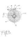
Figure 3 is a plan view of an embodiment of the operating shaft, power shaft and spring assemblies used in a drive mechanism according to the invention; -
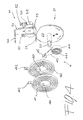
Figure 4 is an exploded view of the assemblies offigure 3 ; -
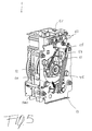
Figure 5 is rear view of a drive mechanism according to the invention, with the latching and release means in a first operating position; -
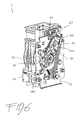
Figure 6 is rear view of a drive mechanism offigure 5 , with the latching and release means in a second operating position; -
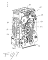
Figure 7 is rear view of a drive mechanism offigure 5 , with the latching and release means in a third operating position; -
Figure 8 is rear view of a drive mechanism offigure 5 , with the latching and release means in a fourth operating position. - With reference to the attached figures, a drive mechanism for a Medium Voltage fuse switch according to the invention, globally designated with the
reference numeral 1, generally comprises abase plate 10 and afront plate 11 that define an internal space. Additional plates,e.g. plate 13, can also be present between thefront 11 andbase 10 plate. The drive mechanism also comprises a number of components for its connection to a Medium Voltage switch that can be of conventional type and that will not described in details. - An
operating shaft 2 and a power shaft are housed in said internal space and are coaxially mounted along a first longitudinal axis, the power shaft being operatively connectable to a kinematic chain of a Medium Voltage fuse switch through conventional linking system to actuate the opening/closing operation of said switch. Theoperating shaft 2 has ahead 20 connectable to an operating handle for manual actuation of said operating shaft, through a hole positioned on thefront plate 11 of thedrive mechanism 1. - The
drive mechanism 1 of the invention further comprises a spring assembly 4 which comprises a first 41 and a second 42 spiral springs, also positioned in the internal space between thebase plate 10 and thefront plate 11. - The first and second
spiral springs first end operating shaft 2 and asecond end 412 operatively couplable to said power shaft. The first and secondspiral springs operating shaft 2 and actuates said power shaft when released, the firstspiral spring 41 determining a rotation of said power shaft in an opposite direction with respect to the rotation determined by said secondspiral spring 42. - One of the characterizing features of the
drive mechanism 1 according to the invention resides in that it is provided with latching means 5 for latching said power shaft, said latching means comprising a first 51 and a second 52 latching arm which are positioned on said power shaft . - A further characteristics of the
drive mechanism 1 according to the invention resides in that it is also provided with first 61 and second 62 release means for unlatching said power shaft and allowing rotation thereof; in particular, as better explained hereinafter, the first release means 61 allows a rotation of said power shaft in a direction which is opposite with respect to the rotation allowed by said second release means 62. - In practice, the closing operation is carried out by loading one of said first or second
spiral springs spiral spring 41; once the spring is loaded the power shaft is latched by said latching means 5. In these conditions, the closing spring is loaded, while thepower shaft 2 is latched in a position corresponding to the open position of the contacts of the associated fuse switch. The closing operation is actuated by acting on one of said release means, e.g. the release means 61, thereby unlatching the power shaft and allowing a rotation of said power arm in a first direction, e.g. clockwise with respect to a front view of thedrive mechanism 1. - Correspondingly, the opening operation is carried out by loading the other one of said first or second
spiral springs spiral spring 42; once the spring is loaded the power shaft is latched by said latching means 5. In these conditions, the opening spring is loaded, while thepower shaft 2 is latched in a position corresponding to the closed position of the contacts of the associated fuse switch. The opening operation is actuated by acting on one of said release means, e.g. the release means 62, thereby unlatching the power shaft and allowing a rotation of said power arm in a second direction which is opposite with respect to the rotation allowed by said secondfirst means 61, e.g., in this case, counterclockwise with respect to a front view of thedrive mechanism 1. - Loading of the
spiral springs - With reference to
figure 3 and4 , in thedrive mechanism 1 according to the invention, theoperating shaft 2 preferably comprises afirst subassembly 21 which in turns comprises adisk 22 of substantially circular shape which is mounted perpendicularly with respect to said first longitudinal axis and further comprises afirst plate element 23 which protrudes perpendicularly from the edge of saiddisk 22 in the direction of thehead 20 of saidoperating shaft 2. Thefirst plate element 23 is operatively couplable to thesecond ends - According to a preferred embodiment of the invention, the spring assembly 4 preferably comprises a
first lever 43 which has abase element 44 coaxially mounted on thefirst subassembly 21 of saidoperating shaft 2 in correspondence of thedisk 22. Thebase element 44 of thefirst lever 43 is conveniently provided withfixing means 441 for thefirst ends spiral springs - A
distal end 45 of saidfirst lever 43 protrudes form the edge of saiddisk 22 and is operatively coupled with saidfirst plate element 23 of saidfirst subassembly 21. - According to a particularly preferred embodiment of the
drive mechanism 1 of the invention, saidfirst lever 43 comprisesadjusting means 46 which are operatively coupled to saidfirst plate element 23 for adjusting the preload of said first 41 and second 42 spiral springs. In this way the speed characteristics of the first and second springs, 41 and 42, can be changed, or at least fine-tuned, according to needs, thereby allowing accurate calibration of the speed characteristics of the drive mechanism and/or compensating variations due to, e.g., aging of the spring itself or other mechanical components of the drive mechanism and/or of the switch. In particular, the adjusting means 46 are preferably positioned so as to cooperate with saidfirst plate element 23 of saidoperating shaft 2. In practice, according to this embodiment, the adjusting means 46 allow to rotate the first lever 40 (onto which the first ends, 411 and 412, of the first and second spiral springs, 41 and 42, are fixed) with respect to thedisk 22 of theoperating shaft 2, thereby changing the pre-load of thespiral springs - As an example, said adjusting means 40 can comprise a hole, preferably a threaded hole, positioned on the
distal end portion 45 of saidfirst lever 43 and screw means 48 inserted in said hole and abutting against thefirst plate element 23 of saidoperating shaft 2. Thus, by rotating thescrew 48, thesecond lever 42 can be rotated to a more or less great extent with respect to theoperating shaft 2, consequently changing the pre-load applied to thespiral springs - Preferably, the power shaft comprises a
second subassembly 31 comprising a second, L shaped,lever 32 having aflat base 33 rotationally mounted along said first longitudinal axis perpendicularly thereto; asecond plate element 34 protrudes perpendicularly from saidflat base 33 in the direction of thehead 20 of saidoperating shaft 2. - In practice, the first 23 and second 34 plate elements protrudes respectively from the
disk 22 and theflat base 33 along parallel directions. Also, saidsecond plate element 34 is positioned at a distance from said first longitudinal axis which is greater than the distance of saidfirst plate element 23 from said first longitudinal axis; in other words, the length of theflat base 33 is greater than the diameter of thedisk 22. Preferably, as shown infigure 4 , the length of thesecond plate element 34 is greater than the length of saidfirst plate element 23. - As shown in the attached figures, the preferably the
second plate element 34 is operatively couplable with the second ends, 412 and 422, of said first and second spiral springs, 41 and 42. - Preferably, the
second subassembly 31 of the power shaft further comprises amain body 35 having afirst side 36 which is fixed to theflat base 33 of said second, L shaped,lever 32. Saidmain body 35 has a second side, e.g. parallel and opposite to saidfirst side 36, onto which said first 51 and second 52 latching arm are positioned. - With reference to
figure 2 and5-8 , according to a preferred embodiment of thedrive mechanism 1 of the invention, said latching means 5 comprises a first 53 and a second 54 latching pawls slidingly mounted on athird plate 13; the first 53 and second 54 sliding latching pawls are movable between a latching position and a released position and are operatively associable respectively with said first 51 and second 52 latching arm. - Also, according to a particularly preferred embodiment of the
drive mechanism 1 of the invention, said first 61 and second 62 release means comprise a first 610 and a second 620 release buttons positioned on the front of saiddrive mechanism 1. - In details, the functioning will be explained with reference to
figures 5-8 , showing a preferred embodiment of the invention.. - With reference to figure said figures, said first 53 and second 54 latching sliding pawl are slidingly mounted in a corresponding groove, 530 and 540, in a
third plate 13, positioned in between saidbase 10 andfront 11 plates. -
Figure 5 shows an operating situation in which the first and second spiral springs, 41 and 42, are loaded and the power shaft 3 is kept by the latching means 5 in a position corresponding to the open position of the contacts of an associated switch. - According to this embodiment, in such a situation, the first sliding
pawl 53 is kept in a first latching position by afirst latching lever 55, in which first latching position the firstlatching sliding pawl 53 abuts against said first latchingarm 51. - With reference to
figure 6 , when said first latchinglever 55 is released, the firstlatching sliding pawl 53 slides in thegroove 530 and is moved in a first releasing position, in which first releasing position the power shaft is free to rotate in a first direction, in the present case counterclockwise with respect to a rear view of thedrive mechanism 1. - The power arm rotates transmitting motion and energy to the contact system of the associated switch till the position of
figure 7 is reached. In such a position, the power shaft is kept by the latching means 5 in a position corresponding to a situation of closed contacts in the associated switch, one of the two spiral springs is release while the other one is still loaded. - In the position of
figure 7 , the secondlatching sliding pawl 54 is kept in a second latching position by a second latching lever, which is not shown since hidden by thethird plate 13, but which is similar to thefirst latching lever 55. As shown infigure 7 , in said second latching position, the secondlatching sliding pawl 54 abuts against said second latchingarm 52 mounted on the power shaft. - As shown in
figure 8 , when said second latching lever is released, the secondlatching sliding pawl 54 slides in thegroove 540 and is moved in a second releasing position, in which second releasing position the power shaft is free to rotate in a second direction which is opposite to said first direction, in the present case clockwise with respect to a rear view of thedrive mechanism 1. - The power arm thus rotates, transmitting motion and energy to the contact system of the associated switch till it reaches a position corresponding to the its position of
figure 7 . In such a position, the power shaft is in a position corresponding to a situation of open contacts in the associated switch, both spiral springs 41 and 42 being released. - Preferably, the latching means 5 comprises a first 57 and a second locking means for respectively locking said first 55 and second latching levers. The second locking means are not shown since hidden by the
third plate 13, but they are similar to the first locking means 57. - The first locking means 57 can be for example consist of a rotating pin having a first position (
fig. 5 ) in which it interferes with thefirst latching lever 55 blocking it, and a second position (fig. 6 ) in which first latchinglever 55 is released. Similar set-up is possible also for the second locking means and the second latching lever. - The first 57 and second locking means are conveniently actuated by said first 610 and a second 620 release buttons. A lever system, comprises, levers 630, 640, and 650 can be foreseen for connecting the
release button 620 with the associated second locking means . Also, return springs 550 and 540 can also be foreseen to help the return into position of the first 55 and second latching levers. - In a particularly preferred embodiment of the
drive mechanism 1 according to the invention, asecond operating shaft 9 is also present. Thesecond operating shaft 9 is preferably mounted on a second longitudinal axis parallel to said first longitudinal axis and can be advantageously used to carry out the earthing operation of the switch acting on a shaft which is independent from the first (main) operatingshaft 2 which is used for the opening and closing operation. - As it can be seen from the above description, the
drive mechanism 1 for a Medium Voltage switch, in particular for a Medium Voltage fuse switch, of the present invention has a number of advantages with respect to the Medium Voltage switches equipped with conventional drive mechanisms. - In particular, the opening/closing operation can be easily actuated by acting on the
release buttons - Also, the presence of the adjusting means 46 does not require an excessively accurate dimensioning and pre-testing of the spiral springs 41 and 42, since the speed characteristics of the springs can be calibrated and fine-tuned after assembling. Moreover, the adjusting means 46 allow adjusting the speed characteristics of the spiral springs 41 and 42, in case of variation over the time of the characteristics of the spring itself and/or of the associated mechanical components.
- It is worth noting that the above mentioned functionalities (i.e., releasing means and adjusting means) can be implemented in a relatively easy manner, with a reduced number of components of relatively simple structure. Thus, the drive mechanism of the invention is also effective from an economical standpoint.
- In general, the structure of the drive mechanism of the invention is very compact and can be adapted, with only a few modification, to a number of different Medium Voltage applications.
- The drive mechanism for a Medium Voltage fuse switch of the invention can also comprise further components and functionalities that have not been described in details as they can be of conventional kind, as defined in the claims.
Claims (11)
- A drive mechanism (1) for a Medium Voltage fuse switch characterized in that it comprises:- a base plate (10) and a front plate (11) defining an internal space housing an operating shaft (2) and a power shaft coaxially mounted along a first longitudinal axis, the power shaft being operatively connectable to a kinematic chain of a Medium Voltage fuse switch for opening/closing operation of said switch, the operating shaft (2) having a head (20) connectable to an operating handle for manual actuation of said operating shaft (2);- a spring assembly (4) which comprises a first (41) and a second (42) spiral springs having a first end (411, 421) operatively coupled to said operating shaft (2) said spiral springs (41, 42) being loaded by rotation of said operating shaft (2) and actuating said power shaft when released, the first spiral spring (41) determining a rotation of said power shaft in an opposite direction with respect to the rotation determined by said second spiral spring (42);- latching means (5) for latching said power shaft comprising a first (51) and a second (52) latching arm positioned on said power shaft ;- first (61) and second (62) release means for unlatching said power shaft and allowing rotation thereof, the first release means (61) allowing a rotation of said power shaft in an opposite direction with respect to said second release means (62); characterised by- said operating shaft (2) comprising a first subassembly (21) comprising a disk (22) perpendicularly mounted with respect to said first longitudinal axis and further comprising a first plate element (23) protruding perpendicularly from the edge of said disk (22) in the direction of the head (20) of said operating shaft (2).
- The drive mechanism (1) according to claim 1, characterized in that said spring assembly (4) comprises a first lever (43) having a base element (44) coaxially mounted on the first subassembly (21) of said operating shaft (2) and a distal end (45) protruding form the edge of said disk (22), said base element (44) being provided with fixing means (441) for the first ends (411, 421) of said first and second spiral springs (41, 42), said distal end (45) being operatively coupled with said first plate element (23) of said first subassembly (21).
- The drive mechanism (1) according to claim 2, characterized in that said fixing means (441) comprises a groove in which said first ends (411, 412) of said first and second spiral springs (41, 42) are secured, and further characterized in that said distal end (45) of said first lever (43) comprises adjusting means (46) operatively coupled to said first plate element (23) for adjusting the preload of said first (41) and second (42) spiral springs.
- The drive mechanism (1) according to one or more of the preceding claims, characterized in that said power shaft comprises a second subassembly (31) comprising a second, L shaped, lever (32) having a flat base (33) rotationally mounted along said first longitudinal axis perpendicularly thereto, and a second plate element (34) perpendicularly protruding from said flat base (33) in the direction of the head (20) of said operating shaft (2), the second subassembly (31) further comprising a main body (35) having a first side (36) fixed to the flat base (33) of said second, L shaped, lever (32) and a second side onto which said first (51) and second (52) latching arm are positioned.
- The drive mechanism (1) according to claim 4, characterized in that said second plate element (34) is operatively couplable with the second ends (412, 422) of said first and second spiral springs (41, 42).
- The drive mechanism (1) according to one or more of the preceding claims, characterized in that said latching means (5) comprises a first (53) and a second (54) latching sliding pawl slidingly mounted on a third plate (13) and movable between a latching position and a released position and operatively associable with said first (51) and second (52) latching arm.
- The drive mechanism (1) according to claim 6, characterized in that said first (53) and second (54) latching sliding pawl are slidingly mounted in a corresponding groove (530, 540) in said third plate (13), the first sliding pawl (53) being kept in a first latching position by a first latching lever (55), in which first latching position said first latching sliding pawl (53) abuts against said first latching arm (51), said first latching sliding pawl (53) being moved in a first releasing position when said first latching lever (55) is released, in which first releasing position the power shaft is free to rotate in a first direction, the second latching sliding pawl (54) being kept in a second latching position by a second latching lever, in which second latching position said second latching sliding pawl (54) abuts against said second latching arm (52), said second latching sliding pawl (54) being moved in a second releasing position when said second latching lever is released, in which second releasing position the power shaft (3) is free to rotate in a second direction opposite to said first direction.
- The drive mechanism (1) according to claim 7, characterized in that said latching means (5) comprises a first (57) and a second locking means for respectively locking said first (55) and second (56) latching levers.
- The drive mechanism (1) according to one or more of the preceding claims, characterized in that said first (61) and second (62) release means comprise a first (610) and a second (620) release buttons positioned on the front of said drive mechanism (1).
- The drive mechanism (1) according to claims 8 and 9, characterized in that said first (610) and a second (620) release buttons respectively act on said first (57) and second locking means.
- A Medium Voltage fuse switch characterized in that it comprises a drive mechanism (1) according to one or more of the preceding claims.
Priority Applications (6)
| Application Number | Priority Date | Filing Date | Title |
|---|---|---|---|
| PL09159345T PL2249361T3 (en) | 2009-05-04 | 2009-05-04 | Drive mechanism for medium voltage fuse switches. |
| ES09159345T ES2389590T3 (en) | 2009-05-04 | 2009-05-04 | Transmission mechanism for medium voltage fuse switches |
| EP09159345A EP2249361B1 (en) | 2009-05-04 | 2009-05-04 | Drive mechanism for medium voltage fuse switches. |
| CN200910206348.5A CN101882512B (en) | 2009-05-04 | 2009-10-15 | Drive mechanism for medium voltage fuse switch and corresponding medium voltage fuse switch |
| CN200920178756XU CN201556539U (en) | 2009-05-04 | 2009-10-15 | Driving mechanism for medium-voltage fuse switch and corresponding medium-voltage fuse switch |
| RU2010117356/07A RU2536167C2 (en) | 2009-05-04 | 2010-04-30 | Drive mechanism for medium voltage fuse switches |
Applications Claiming Priority (1)
| Application Number | Priority Date | Filing Date | Title |
|---|---|---|---|
| EP09159345A EP2249361B1 (en) | 2009-05-04 | 2009-05-04 | Drive mechanism for medium voltage fuse switches. |
Publications (2)
| Publication Number | Publication Date |
|---|---|
| EP2249361A1 EP2249361A1 (en) | 2010-11-10 |
| EP2249361B1 true EP2249361B1 (en) | 2012-07-11 |
Family
ID=41050316
Family Applications (1)
| Application Number | Title | Priority Date | Filing Date |
|---|---|---|---|
| EP09159345A Active EP2249361B1 (en) | 2009-05-04 | 2009-05-04 | Drive mechanism for medium voltage fuse switches. |
Country Status (5)
| Country | Link |
|---|---|
| EP (1) | EP2249361B1 (en) |
| CN (2) | CN201556539U (en) |
| ES (1) | ES2389590T3 (en) |
| PL (1) | PL2249361T3 (en) |
| RU (1) | RU2536167C2 (en) |
Families Citing this family (6)
| Publication number | Priority date | Publication date | Assignee | Title |
|---|---|---|---|---|
| ES2389590T3 (en) * | 2009-05-04 | 2012-10-29 | Abb Technology Ag | Transmission mechanism for medium voltage fuse switches |
| US9373456B2 (en) * | 2014-04-24 | 2016-06-21 | Eaton Corporation | Circuit breakers with clock spring drives and/or multi-lobe drive cams and related actuators and methods |
| US9472359B2 (en) | 2014-04-24 | 2016-10-18 | Eaton Corporation | Trip latch assemblies for circuit breakers and related circuit breakers |
| DE102017216805B4 (en) * | 2017-09-22 | 2020-10-29 | Siemens Aktiengesellschaft | Tensioning gear for tensioning a storage spring of a spring storage drive |
| CN109065416B (en) * | 2018-10-26 | 2024-02-13 | 江苏创源电子有限公司 | Fuse leading-in equipment |
| CN109309353A (en) * | 2018-11-22 | 2019-02-05 | 国网吉林省电力有限公司经济技术研究院 | A kind of change of fuse tool |
Family Cites Families (8)
| Publication number | Priority date | Publication date | Assignee | Title |
|---|---|---|---|---|
| SU438060A1 (en) * | 1972-05-29 | 1974-07-30 | Ульяновский политехнический институт | Safety switch |
| SU517068A1 (en) * | 1974-02-15 | 1976-06-05 | Предприятие П/Я А-7211 | Switch actuator |
| US4578551A (en) * | 1985-04-10 | 1986-03-25 | S&C Electric Company | Operating mechanism for electrical switches |
| US4683357A (en) * | 1985-12-19 | 1987-07-28 | S&C Electric Company | Switch-operating mechanism with improved charging arrangement |
| SU1554058A1 (en) * | 1987-04-06 | 1990-03-30 | Предприятие П/Я В-8117 | Device for manufacturing hyperbolic contact units |
| FR2740621B1 (en) * | 1995-10-26 | 1997-11-21 | Gec Alsthom T & D Sa | SHIELDED MEDIUM VOLTAGE STATION |
| RU2110105C1 (en) * | 1996-03-19 | 1998-04-27 | Российский Федеральный Ядерный Центр - Всероссийский Научно-Исследовательский Институт Экспериментальной Физики | Driving mechanism of switch |
| ES2389590T3 (en) * | 2009-05-04 | 2012-10-29 | Abb Technology Ag | Transmission mechanism for medium voltage fuse switches |
-
2009
- 2009-05-04 ES ES09159345T patent/ES2389590T3/en active Active
- 2009-05-04 PL PL09159345T patent/PL2249361T3/en unknown
- 2009-05-04 EP EP09159345A patent/EP2249361B1/en active Active
- 2009-10-15 CN CN200920178756XU patent/CN201556539U/en not_active Expired - Lifetime
- 2009-10-15 CN CN200910206348.5A patent/CN101882512B/en active Active
-
2010
- 2010-04-30 RU RU2010117356/07A patent/RU2536167C2/en active
Also Published As
| Publication number | Publication date |
|---|---|
| RU2536167C2 (en) | 2014-12-20 |
| RU2010117356A (en) | 2011-11-10 |
| PL2249361T3 (en) | 2012-12-31 |
| CN101882512A (en) | 2010-11-10 |
| CN101882512B (en) | 2014-06-25 |
| EP2249361A1 (en) | 2010-11-10 |
| ES2389590T3 (en) | 2012-10-29 |
| CN201556539U (en) | 2010-08-18 |
Similar Documents
| Publication | Publication Date | Title |
|---|---|---|
| EP2249361B1 (en) | Drive mechanism for medium voltage fuse switches. | |
| US6685239B2 (en) | Vehicle door opening closing device | |
| US20110169282A1 (en) | Lock unit having a multi-part pawl and a spring-loaded blocking pawl | |
| US7161100B1 (en) | Limit switch mechanism for door opening | |
| US8267444B2 (en) | Door lock apparatus for vehicle | |
| EP1575074B1 (en) | Switch mechanism | |
| EP2277187B1 (en) | Electrical switching apparatus, and charging assembly and interlock assembly therefor | |
| US20170234427A1 (en) | Locking arrangement | |
| US8232488B2 (en) | Operating mechanism for a switching device | |
| CA2857608C (en) | Locking mechanism for a switch-on button of a circuit breaker | |
| US9903143B2 (en) | Switch assembly of vehicle door latch device | |
| US7724112B2 (en) | Safety switch | |
| US9373455B2 (en) | Spring-operated mechanism having delay circuit | |
| EP2249360B1 (en) | Drive mechanism for medium voltage switch | |
| US8629743B2 (en) | Latching apparatus and an operating mechanism with such a latching apparatus | |
| KR100424355B1 (en) | Alarm devices for circuit breakers | |
| CN110783122A (en) | Neutral position limit switch head design with reduced components and improved reliability | |
| US2750477A (en) | Switch | |
| EP2249366B1 (en) | Signalling device for circuit breaker and electrical apparatus comprising the signalling device | |
| US10896796B2 (en) | Switching system, and electrical switching apparatus and switching assembly therefor | |
| US7351924B2 (en) | Key switch with a device for key monitoring | |
| KR200398419Y1 (en) | Multiple Link Operating Mechanism for Vacuum Circuit Breaker | |
| US7106155B2 (en) | Double-lever mechanism, trip actuator assembly and electrical switching apparatus employing the same | |
| CN117790210A (en) | Energy storage mechanism for state switching operation of electrical control system | |
| CN110931278A (en) | Actuation system for an electrical switching apparatus |
Legal Events
| Date | Code | Title | Description |
|---|---|---|---|
| PUAI | Public reference made under article 153(3) epc to a published international application that has entered the european phase |
Free format text: ORIGINAL CODE: 0009012 |
|
| AK | Designated contracting states |
Kind code of ref document: A1 Designated state(s): AT BE BG CH CY CZ DE DK EE ES FI FR GB GR HR HU IE IS IT LI LT LU LV MC MK MT NL NO PL PT RO SE SI SK TR |
|
| 17P | Request for examination filed |
Effective date: 20110510 |
|
| GRAP | Despatch of communication of intention to grant a patent |
Free format text: ORIGINAL CODE: EPIDOSNIGR1 |
|
| GRAS | Grant fee paid |
Free format text: ORIGINAL CODE: EPIDOSNIGR3 |
|
| GRAA | (expected) grant |
Free format text: ORIGINAL CODE: 0009210 |
|
| AK | Designated contracting states |
Kind code of ref document: B1 Designated state(s): AT BE BG CH CY CZ DE DK EE ES FI FR GB GR HR HU IE IS IT LI LT LU LV MC MK MT NL NO PL PT RO SE SI SK TR |
|
| REG | Reference to a national code |
Ref country code: GB Ref legal event code: FG4D |
|
| REG | Reference to a national code |
Ref country code: CH Ref legal event code: EP |
|
| REG | Reference to a national code |
Ref country code: AT Ref legal event code: REF Ref document number: 566488 Country of ref document: AT Kind code of ref document: T Effective date: 20120715 |
|
| REG | Reference to a national code |
Ref country code: IE Ref legal event code: FG4D |
|
| REG | Reference to a national code |
Ref country code: DE Ref legal event code: R096 Ref document number: 602009008155 Country of ref document: DE Effective date: 20120906 |
|
| REG | Reference to a national code |
Ref country code: RO Ref legal event code: EPE |
|
| REG | Reference to a national code |
Ref country code: ES Ref legal event code: FG2A Ref document number: 2389590 Country of ref document: ES Kind code of ref document: T3 Effective date: 20121029 |
|
| REG | Reference to a national code |
Ref country code: NO Ref legal event code: T2 Effective date: 20120711 |
|
| REG | Reference to a national code |
Ref country code: NL Ref legal event code: VDEP Effective date: 20120711 |
|
| REG | Reference to a national code |
Ref country code: AT Ref legal event code: MK05 Ref document number: 566488 Country of ref document: AT Kind code of ref document: T Effective date: 20120711 |
|
| REG | Reference to a national code |
Ref country code: LT Ref legal event code: MG4D Effective date: 20120711 |
|
| REG | Reference to a national code |
Ref country code: PL Ref legal event code: T3 |
|
| PG25 | Lapsed in a contracting state [announced via postgrant information from national office to epo] |
Ref country code: HR Free format text: LAPSE BECAUSE OF FAILURE TO SUBMIT A TRANSLATION OF THE DESCRIPTION OR TO PAY THE FEE WITHIN THE PRESCRIBED TIME-LIMIT Effective date: 20120711 Ref country code: IS Free format text: LAPSE BECAUSE OF FAILURE TO SUBMIT A TRANSLATION OF THE DESCRIPTION OR TO PAY THE FEE WITHIN THE PRESCRIBED TIME-LIMIT Effective date: 20121111 Ref country code: LT Free format text: LAPSE BECAUSE OF FAILURE TO SUBMIT A TRANSLATION OF THE DESCRIPTION OR TO PAY THE FEE WITHIN THE PRESCRIBED TIME-LIMIT Effective date: 20120711 Ref country code: CY Free format text: LAPSE BECAUSE OF FAILURE TO SUBMIT A TRANSLATION OF THE DESCRIPTION OR TO PAY THE FEE WITHIN THE PRESCRIBED TIME-LIMIT Effective date: 20120711 Ref country code: AT Free format text: LAPSE BECAUSE OF FAILURE TO SUBMIT A TRANSLATION OF THE DESCRIPTION OR TO PAY THE FEE WITHIN THE PRESCRIBED TIME-LIMIT Effective date: 20120711 |
|
| PG25 | Lapsed in a contracting state [announced via postgrant information from national office to epo] |
Ref country code: SI Free format text: LAPSE BECAUSE OF FAILURE TO SUBMIT A TRANSLATION OF THE DESCRIPTION OR TO PAY THE FEE WITHIN THE PRESCRIBED TIME-LIMIT Effective date: 20120711 Ref country code: LV Free format text: LAPSE BECAUSE OF FAILURE TO SUBMIT A TRANSLATION OF THE DESCRIPTION OR TO PAY THE FEE WITHIN THE PRESCRIBED TIME-LIMIT Effective date: 20120711 Ref country code: PT Free format text: LAPSE BECAUSE OF FAILURE TO SUBMIT A TRANSLATION OF THE DESCRIPTION OR TO PAY THE FEE WITHIN THE PRESCRIBED TIME-LIMIT Effective date: 20121112 Ref country code: SE Free format text: LAPSE BECAUSE OF FAILURE TO SUBMIT A TRANSLATION OF THE DESCRIPTION OR TO PAY THE FEE WITHIN THE PRESCRIBED TIME-LIMIT Effective date: 20120711 Ref country code: GR Free format text: LAPSE BECAUSE OF FAILURE TO SUBMIT A TRANSLATION OF THE DESCRIPTION OR TO PAY THE FEE WITHIN THE PRESCRIBED TIME-LIMIT Effective date: 20121012 |
|
| PG25 | Lapsed in a contracting state [announced via postgrant information from national office to epo] |
Ref country code: NL Free format text: LAPSE BECAUSE OF FAILURE TO SUBMIT A TRANSLATION OF THE DESCRIPTION OR TO PAY THE FEE WITHIN THE PRESCRIBED TIME-LIMIT Effective date: 20120711 |
|
| PG25 | Lapsed in a contracting state [announced via postgrant information from national office to epo] |
Ref country code: DK Free format text: LAPSE BECAUSE OF FAILURE TO SUBMIT A TRANSLATION OF THE DESCRIPTION OR TO PAY THE FEE WITHIN THE PRESCRIBED TIME-LIMIT Effective date: 20120711 Ref country code: EE Free format text: LAPSE BECAUSE OF FAILURE TO SUBMIT A TRANSLATION OF THE DESCRIPTION OR TO PAY THE FEE WITHIN THE PRESCRIBED TIME-LIMIT Effective date: 20120711 |
|
| PLBE | No opposition filed within time limit |
Free format text: ORIGINAL CODE: 0009261 |
|
| STAA | Information on the status of an ep patent application or granted ep patent |
Free format text: STATUS: NO OPPOSITION FILED WITHIN TIME LIMIT |
|
| PG25 | Lapsed in a contracting state [announced via postgrant information from national office to epo] |
Ref country code: SK Free format text: LAPSE BECAUSE OF FAILURE TO SUBMIT A TRANSLATION OF THE DESCRIPTION OR TO PAY THE FEE WITHIN THE PRESCRIBED TIME-LIMIT Effective date: 20120711 |
|
| 26N | No opposition filed |
Effective date: 20130412 |
|
| PG25 | Lapsed in a contracting state [announced via postgrant information from national office to epo] |
Ref country code: BG Free format text: LAPSE BECAUSE OF FAILURE TO SUBMIT A TRANSLATION OF THE DESCRIPTION OR TO PAY THE FEE WITHIN THE PRESCRIBED TIME-LIMIT Effective date: 20121011 |
|
| REG | Reference to a national code |
Ref country code: DE Ref legal event code: R097 Ref document number: 602009008155 Country of ref document: DE Effective date: 20130412 |
|
| PG25 | Lapsed in a contracting state [announced via postgrant information from national office to epo] |
Ref country code: MC Free format text: LAPSE BECAUSE OF FAILURE TO SUBMIT A TRANSLATION OF THE DESCRIPTION OR TO PAY THE FEE WITHIN THE PRESCRIBED TIME-LIMIT Effective date: 20120711 |
|
| REG | Reference to a national code |
Ref country code: CH Ref legal event code: PL |
|
| PG25 | Lapsed in a contracting state [announced via postgrant information from national office to epo] |
Ref country code: CH Free format text: LAPSE BECAUSE OF NON-PAYMENT OF DUE FEES Effective date: 20130531 Ref country code: LI Free format text: LAPSE BECAUSE OF NON-PAYMENT OF DUE FEES Effective date: 20130531 |
|
| REG | Reference to a national code |
Ref country code: IE Ref legal event code: MM4A |
|
| PG25 | Lapsed in a contracting state [announced via postgrant information from national office to epo] |
Ref country code: IE Free format text: LAPSE BECAUSE OF NON-PAYMENT OF DUE FEES Effective date: 20130504 |
|
| PG25 | Lapsed in a contracting state [announced via postgrant information from national office to epo] |
Ref country code: MT Free format text: LAPSE BECAUSE OF FAILURE TO SUBMIT A TRANSLATION OF THE DESCRIPTION OR TO PAY THE FEE WITHIN THE PRESCRIBED TIME-LIMIT Effective date: 20120711 |
|
| PG25 | Lapsed in a contracting state [announced via postgrant information from national office to epo] |
Ref country code: TR Free format text: LAPSE BECAUSE OF FAILURE TO SUBMIT A TRANSLATION OF THE DESCRIPTION OR TO PAY THE FEE WITHIN THE PRESCRIBED TIME-LIMIT Effective date: 20120711 |
|
| PG25 | Lapsed in a contracting state [announced via postgrant information from national office to epo] |
Ref country code: LU Free format text: LAPSE BECAUSE OF NON-PAYMENT OF DUE FEES Effective date: 20130504 Ref country code: HU Free format text: LAPSE BECAUSE OF FAILURE TO SUBMIT A TRANSLATION OF THE DESCRIPTION OR TO PAY THE FEE WITHIN THE PRESCRIBED TIME-LIMIT; INVALID AB INITIO Effective date: 20090504 Ref country code: MK Free format text: LAPSE BECAUSE OF FAILURE TO SUBMIT A TRANSLATION OF THE DESCRIPTION OR TO PAY THE FEE WITHIN THE PRESCRIBED TIME-LIMIT Effective date: 20120711 |
|
| REG | Reference to a national code |
Ref country code: FR Ref legal event code: PLFP Year of fee payment: 8 |
|
| REG | Reference to a national code |
Ref country code: DE Ref legal event code: R082 Ref document number: 602009008155 Country of ref document: DE Representative=s name: KUHNEN & WACKER PATENT- UND RECHTSANWALTSBUERO, DE Ref country code: DE Ref legal event code: R081 Ref document number: 602009008155 Country of ref document: DE Owner name: ABB SCHWEIZ AG, CH Free format text: FORMER OWNER: ABB TECHNOLOGY AG, ZUERICH, CH |
|
| REG | Reference to a national code |
Ref country code: FR Ref legal event code: PLFP Year of fee payment: 9 |
|
| REG | Reference to a national code |
Ref country code: ES Ref legal event code: PC2A Owner name: ABB SCHWEIZ AG Effective date: 20171213 |
|
| REG | Reference to a national code |
Ref country code: BE Ref legal event code: PD Owner name: ABB SCHWEIZ AG; CH Free format text: DETAILS ASSIGNMENT: CHANGE OF OWNER(S), CESSION; FORMER OWNER NAME: ABB TECHNOLOGY AG Effective date: 20180112 |
|
| REG | Reference to a national code |
Ref country code: NO Ref legal event code: CHAD Owner name: ABB SCHWEIZ AG, CH |
|
| REG | Reference to a national code |
Ref country code: FR Ref legal event code: PLFP Year of fee payment: 10 |
|
| REG | Reference to a national code |
Ref country code: GB Ref legal event code: 732E Free format text: REGISTERED BETWEEN 20180426 AND 20180502 |
|
| PGFP | Annual fee paid to national office [announced via postgrant information from national office to epo] |
Ref country code: BE Payment date: 20180518 Year of fee payment: 10 |
|
| REG | Reference to a national code |
Ref country code: FR Ref legal event code: TP Owner name: ABB SCHWEIZ AG, CH Effective date: 20180912 |
|
| PGFP | Annual fee paid to national office [announced via postgrant information from national office to epo] |
Ref country code: RO Payment date: 20190502 Year of fee payment: 11 |
|
| REG | Reference to a national code |
Ref country code: BE Ref legal event code: MM Effective date: 20190531 |
|
| PG25 | Lapsed in a contracting state [announced via postgrant information from national office to epo] |
Ref country code: BE Free format text: LAPSE BECAUSE OF NON-PAYMENT OF DUE FEES Effective date: 20190531 |
|
| PG25 | Lapsed in a contracting state [announced via postgrant information from national office to epo] |
Ref country code: RO Free format text: LAPSE BECAUSE OF NON-PAYMENT OF DUE FEES Effective date: 20200504 |
|
| PGFP | Annual fee paid to national office [announced via postgrant information from national office to epo] |
Ref country code: PL Payment date: 20190430 Year of fee payment: 11 |
|
| PG25 | Lapsed in a contracting state [announced via postgrant information from national office to epo] |
Ref country code: PL Free format text: LAPSE BECAUSE OF NON-PAYMENT OF DUE FEES Effective date: 20200504 |
|
| PGFP | Annual fee paid to national office [announced via postgrant information from national office to epo] |
Ref country code: NO Payment date: 20230523 Year of fee payment: 15 Ref country code: IT Payment date: 20230526 Year of fee payment: 15 Ref country code: FR Payment date: 20230526 Year of fee payment: 15 Ref country code: DE Payment date: 20230519 Year of fee payment: 15 Ref country code: CZ Payment date: 20230425 Year of fee payment: 15 |
|
| PGFP | Annual fee paid to national office [announced via postgrant information from national office to epo] |
Ref country code: FI Payment date: 20230523 Year of fee payment: 15 |
|
| PGFP | Annual fee paid to national office [announced via postgrant information from national office to epo] |
Ref country code: GB Payment date: 20230524 Year of fee payment: 15 Ref country code: ES Payment date: 20230724 Year of fee payment: 15 |