EP2249307A1 - Method for image reframing - Google Patents
Method for image reframing Download PDFInfo
- Publication number
- EP2249307A1 EP2249307A1 EP10161898A EP10161898A EP2249307A1 EP 2249307 A1 EP2249307 A1 EP 2249307A1 EP 10161898 A EP10161898 A EP 10161898A EP 10161898 A EP10161898 A EP 10161898A EP 2249307 A1 EP2249307 A1 EP 2249307A1
- Authority
- EP
- European Patent Office
- Prior art keywords
- reframing
- image
- saliency
- deformation
- threshold value
- Prior art date
- Legal status (The legal status is an assumption and is not a legal conclusion. Google has not performed a legal analysis and makes no representation as to the accuracy of the status listed.)
- Granted
Links
- 238000000034 method Methods 0.000 title claims abstract description 176
- 238000004458 analytical method Methods 0.000 claims abstract description 36
- 238000001514 detection method Methods 0.000 claims description 33
- 230000001149 cognitive effect Effects 0.000 claims description 18
- 230000000007 visual effect Effects 0.000 description 18
- 230000015654 memory Effects 0.000 description 9
- 230000002207 retinal effect Effects 0.000 description 7
- 230000002123 temporal effect Effects 0.000 description 4
- 238000004364 calculation method Methods 0.000 description 3
- 230000004424 eye movement Effects 0.000 description 3
- 230000006870 function Effects 0.000 description 3
- 230000000873 masking effect Effects 0.000 description 3
- 230000003042 antagnostic effect Effects 0.000 description 2
- 230000008901 benefit Effects 0.000 description 2
- 230000001054 cortical effect Effects 0.000 description 2
- 238000000354 decomposition reaction Methods 0.000 description 2
- 230000004438 eyesight Effects 0.000 description 2
- 230000004927 fusion Effects 0.000 description 2
- 238000003909 pattern recognition Methods 0.000 description 2
- 230000035945 sensitivity Effects 0.000 description 2
- 239000013598 vector Substances 0.000 description 2
- 230000006978 adaptation Effects 0.000 description 1
- 210000004556 brain Anatomy 0.000 description 1
- 230000001427 coherent effect Effects 0.000 description 1
- 239000003086 colorant Substances 0.000 description 1
- 238000010276 construction Methods 0.000 description 1
- 238000001914 filtration Methods 0.000 description 1
- 238000010191 image analysis Methods 0.000 description 1
- 230000010354 integration Effects 0.000 description 1
- 230000001537 neural effect Effects 0.000 description 1
- 230000008447 perception Effects 0.000 description 1
- 230000004044 response Effects 0.000 description 1
- 238000001228 spectrum Methods 0.000 description 1
- 238000007619 statistical method Methods 0.000 description 1
- 230000016776 visual perception Effects 0.000 description 1
Images


Classifications
-
- G06T3/04—
-
- H—ELECTRICITY
- H04—ELECTRIC COMMUNICATION TECHNIQUE
- H04N—PICTORIAL COMMUNICATION, e.g. TELEVISION
- H04N1/00—Scanning, transmission or reproduction of documents or the like, e.g. facsimile transmission; Details thereof
- H04N1/387—Composing, repositioning or otherwise geometrically modifying originals
- H04N1/3872—Repositioning or masking
- H04N1/3873—Repositioning or masking defined only by a limited number of coordinate points or parameters, e.g. corners, centre; for trimming
Definitions
- the invention relates to the general field of image reframing.
- the invention relates to a device and method for reframing an image according to a predefined reframing method to obtain a reframed image for which the format ratio is equal to a target format ratio.
- screens adapted for viewing images or video have heterogeneous formats.
- the target format on which the image/video is to be viewed.
- To reframe an image it is known in the art to delete the same number of columns of pixels on the left and the right of the image so that the format of the reframed image is equal to the target format.
- such a method is not adapted to the reframing of images in the case where the image to be reframed contains important visual information on the right and left edges of the image.
- the invention relates to a method for reframing an image according to at least one predefined reframing method to obtain a reframed image for which the format ratio is equal to a target format ratio.
- the method comprises the following steps:
- the analysis step comprises a step of analysis of the saliency of the image able to associate a saliency value with each pixel of the image and a step of cognitive analysis of the image.
- the cognitive analysis step belongs to the set of cognitive analysis steps comprising:
- the selection step comprises the following steps for:
- the reframing method selected is a method for dynamic reframing without deformation capable of delimiting a part of the image using a reframing window for which the format ratio is equal to the target format ratio.
- the cognitive analysis step comprises a step of detection of a zone of text in the image and the reframing method is selected according to the result of the step of text zone detection.
- the reframing method selected is a non-linear filtering method applied to the entire image.
- the cognitive analysis step when no text zone is detected, also comprises a step of detection of face(s) in the image and the reframing method is selected according to the result of the face(s) detection step.
- the reframing method selected is a dynamic reframing method with deformation, otherwise the reframing method selected is a fixed reframing method without deformation.
- the reframing method selected is a fixed reframing method without deformation, else if the saliency in the image is spread then the reframing method selected is a dynamic reframing method with deformation, otherwise the reframing method selected is a fixed reframing method without deformation.
- the reframing method selected is a fixed reframing method without deformation, otherwise if the two pixels of the image of maximum saliency value are not capable of being comprised in a reframing window of format ratio equal to the target format ratio then the reframing method selected is a dynamic reframing method with deformation, otherwise the reframing method selected is a fixed reframing method without deformation.
- the invention relates moreover to a device for reframing an image according to at least one predefined reframing method to obtain a reframed image for which the format ratio is equal to a target format ratio capable of implementing the steps of the method of the invention.
- the reframing device comprises an image analysis module, a selection module capable of selecting, for the image, the reframing method in a set of at least two reframing methods according to the result of the analysis carried out by the analysis module and a reframing module capable of reframing said image using the reframing method selected.
- the invention relates to the reframing of an image I that is isolated or that belongs to a sequence of more than one images.
- the method for reframing the image I consists in generating from the image I an image Irec for which the format ratio, i.e. the ratio between its width and its height, is equal to a target format ratio R target .
- a reframing method is able to reframe an image of format 4/3 to generate an image at format 16/9.
- the image I to be reframed is composed of pixels or image points to each of which is associated at least one item of image data, for example an item of luminance image data or an item of chrominance image data.
- the reframing method according to the invention can be applied to each image of the sequence to generate a sequence of reframed images.
- FIG. 1 An image I to be reframed is shown on the left part of figure 1 .
- This image I has a height of H pixels and a width of W pixels.
- FIG. 1 On the right part of figure 1 , the image I on which is overlaid a reframing window F is shown.
- the reframing window has a height equal to H and a width WBB that can be adapted according to the target format ratio R target .
- the distances are defined are in the sense of the width of the image.
- the same reframing method according to the invention can be applied in the other sense by considering a reframing window of width W and of adaptable height according to the target format ratio R target .
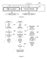
- Figure 2 shows an embodiment of the reframing method according to the invention.
- the image I to be reframed is analyzed. More specifically, the item or items of image data associated with each of its pixels is/are analyzed.
- a particular reframing method is selected according to the result of the analysis carried out in step 100 in a set of at least two predefined reframing methods.
- This set comprises preferably a first dynamic reframing method of the original image without deformation.
- dynamic signifies that the position of the reframing window F in the image can vary from one image to another image in a sequence of several images.
- deformation signifies that the objects in the image I are deformed by the reframing method.
- the reframing method described in the patent application 06117768.9 published in January 31, 2007 under the number EP1748385 is an example of such a dynamic reframing method without deformation.
- the reframed image is generated according to saliency values associated with each pixel of the image I to be reframed.
- Another example of such a method is a manual reframing method in which an operator manually delimits the reframing window F according to the image content and the regions of interest that he identifies in the image.
- This set also comprises a second dynamic reframing method with deformation.
- the method known as seam carving described in the document by S. Avidan and A. Shamir titled "Seam carving for content-aware image resizing" and published in 2007 during the Siggraph conference, is an example of such a dynamic reframing method with deformation.
- this method the pixels of less importance from a visual point of view are deleted to generate the reframed image.
- the importance of pixels is for example represented by a saliency value that is associated with them.
- This set also comprises a third fixed reframing method without deformation.
- This method type consists in extracting a sub-part of the original image based on a cognitive element such as the presence of a face and in conserving this position throughout the scene.
- this method is fixed, as opposed to dynamic, as the position of the reframing window F is the same from one image to another.
- the position of the reframing window is for example based on the face detection in the first image.
- the face detection method described in the document by H. Schneiderman and T. Kanade entitled “A statistical method for 3D object detection applied to faces and cars" and published during the conference IEEE Computer vision and pattern recognition in 2000 can be used.
- This set also comprises a fourth fixed reframing method with deformation.
- this reframing method consists in a deformation of the entire image to obtain an image deformed to the target format ratio.
- a non-linear filter of Lanczos type can be applied over the whole width of the image in order to obtain a reframed image for which the format ratio is equal to the target format ratio R target .
- step 120 the image I is reframed into a reframed image Irec using the reframing method selected in step 100.
- FIG. 3 shows step 100 of the reframing method according to the invention
- the analysis step 100 comprises a step 101 of analysis of the saliency of the image I, i.e. of the perceptual interest of pixels on the image I.
- the method described in the European patent application EP04804828 published 30/06/2005 under the number 1695288 can be used to calculate for each pixel of the image I a data item of perceptual interest also called saliency value.
- This method can be applied in the case where the image I belongs to a sequence of several images.
- This method, illustrated by figure 4 consists in a first spatial modelling step followed by a temporal modelling step.
- the image formed by the saliency values associated with each pixel of the image I is called the saliency map.
- the spatial modelling step is composed of 3 steps 201, 202 and 203.
- the incident image data e.g. RGB components
- the step 201 implements tools that model the human visual system. These tools take into account the fact the human visual system does not appreciate the different visual components of our environment in the same way. This limited sensitivity is simulated by the use of Contrast Sensitivity Functions (CSF) and by the use of intra and inter component visual masking.
- CSF Contrast Sensitivity Functions
- a hierarchic decomposition into perceptual channels marked DCP in figure 4 , simulating the frequency tiling of the visual system is applied to the components (A, Cr1, Cr2) of the space of antagonistic colours of Krauskopf, deduced from the RGB components of an image.
- a set of sub-bands having a radial frequency range and a particular angular selectivity is defined.
- Each subband can actually be considered to be the neuronal image delivered by a population of visual cells reacting to a particular frequency and orientation.
- the CSF function followed by a masking operation is applied to each subband.
- An intra and inter component visual masking operation is then carried out.
- step 202 the sub-bands from the step 201 are convoluted with a close operator of a difference of Gaussians (DoG).
- DoG difference of Gaussians
- the purpose of step 202 is to simulate the visual perception mechanism. This mechanism enables the visual characteristics containing important information to be extracted (particularly local singularities that contrast with their environment) leading to the creation of an economic representation of our environment.
- the organisation of the reception fields of the visual cells whether they are retinal or cortical fully meet this requirement. These cells are circular and are constituted by a centre and an edge having antagonistic responses.
- the cortical cells also have the particularity of having a preferred direction. This organisation endows them with the property of responding strongly on contrasts and of not responding on uniform zones.
- the modelling of this type of cell is carried out via differences of Gaussians (DoG) whether oriented or not.
- DoG Gaussians
- the perception also consists in emphasising some characteristics essential to the interpretation of the information.
- a butterfly filter is applied after the DoG to strengthen the collinear, aligned and small curvature contours.
- the third step 203 consists in constructing the spatial saliency map.
- a fusion of the different components is carried out by grouping or by linking elements, a priori independent, to form an image that can be comprehended by the brain.
- the fusion is based on an intra and inter component competition enabling the complementarity and redundancy of the information carried by different visual dimensions to be used (achromatic or chromatic).
- the temporal modelling step itself divided into 3 steps 204, 205 and 206, is based on the following observation: in an animated context, the contrasts of movement are the most significant visual attractors. Hence, an object moving on a fixed background, or vice versa a fixed object on a moving background, attracts one's visual attention. To determine these contrasts, the recognition of tracking eye movements is vital. These eye movements enable the movement of an object to be compensated for naturally. The velocity of the movement considered expressed in the retinal frame is therefore almost null. To determine the most relevant movement contrasts, it is consequently necessary to compensate for the inherent motion of the camera, assumed to be dominant.
- a field of vectors is estimated at the step 204 by means of a motion estimator working on the hierarchic decomposition into perceptual channels.
- a complete refined parametric model that represents the dominant movement is estimated at the step 205 by means of a robust estimation technique based on M-estimators.
- the retinal movement is then calculated at step 206. It is equal to the difference between the local movement and the dominant movement. The stronger the retinal movement (by accounting nevertheless for the maximum theoretical velocity of the tracking eye movement), the more the zone in question attracts attention.
- the temporal saliency that is proportional to the retinal movement or to the contrast of movement is then deduced from this retinal movement. Given that it is easier to detect a moving object among fixed disturbing elements (or distracters) than the contrary, the retinal movement is modulated by the overall quantity of movement of the scene.
- the spatial and temporal saliency maps are merged in step 207.
- the merging step 207 implements a map intra and inter competition mechanism. Such a map can be presented in the form of a heat map indicating the zones having a high perceptual interest.
- the invention is not limited to the method described in the European patent EP 04804828.4 , which is only an embodiment. Any method enabling the perceptual interest data to be calculated (e.g. in the form of saliency maps) in an image is suitable.
- the method described in the document by Itti et al entitled "A model of saliency-based visual attention for rapid scene analysis” and published in 1998 in IEEE trans. on PAMI can be used to analyse the image I in step 101.
- Step 100 also comprises a cognitive analysis step 102 of the image I.
- a cognitive analysis of an image is an analysis that implicates reconstruction tools from cognitive models for example of representation of the memory and construction of direction. It involves a high level and overall knowledge of the information contained in the image, such as a set of pixels forming an object.
- This step 102 is capable of generating cognitive information.
- FIG. 5 shows a particular embodiment of step 100 of the reframing method according to the invention
- the analysis step 100 comprises the saliency analysis step 101 of the image I and the cognitive analysis step 102 of the image I.
- the cognitive analysis step 102 of the image I comprises a text detection step 1020.
- a text detection step 1020 the method described in the document by S. Ferreira, V. Garin and B. Gosselin entitled "A text detection technique applied in the framework of mobile camera-based application” and published in 2005 during the ICDAR workshop in Proc. of Camera-based Document Analysis and Recognition can be used.
- Any text zone detection method can be used.
- the invention is in no way limited by any one text detection method.
- the text zone detection can be carried out manually on a screen by an operator. More specifically this step is suitable for detecting the position and possibly the size of text zones in the image I.
- a faces detection step 1022 It also comprises a faces detection step 1022.
- the method described in the document by P. Viola and M. Jones entitled “Rapid object detection using a boosted cascade of simple features” and published in 2001 during the conference Computer vision and pattern recognition can be used. Any face detection method can be used.
- the invention is in no way limited by any one face detection method. Hence, the face detection can be carried out manually on a screen by an operator. More specifically this step is suitable for detecting the position of faces in the image I. These faces may be detected in the form of bounding boxes.
- the analysis step 100 comprises a detection step of balls in the image or again a detection step of individual persons or again a detection step of the field during a sports event.
- This object detection step can be carried out manually on screen by an operator.
- the method described in the document by S. Micilotta, E. Ong and R. Bowden entitled “Real-time upper body detection and 3D pose estimation in monoscopic images” and published in 2006 during the ECCV conference can equally be used to detect persons or silhouettes.
- Figures 6 , 7 , 8, and 9 show a particular embodiment of step 110 of the reframing method according to the invention.
- a confidence parameter C is calculated from the saliency map generated at step 101.
- This confidence parameter C is representative of the confidence held in the quality of the reframing carried out using the first reframing method, i.e. dynamic without deformation.
- the thresholds defined above are provided as an example. They may be modified according to the visual attention model selected in step 101 to determine the saliency values.
- a visual attention model has its own representation of the saliency. Hence, depending on the model, a great number of salient elements ordered hierarchically may emerge or conversely only a few pixels may emerge, i.e. have a saliency value other than 0. It is a question of dynamics and of calibration.
- Text_conf is for example defined as follows:
- text_width is the width of the text zone detected, this zone being of rectangular form.
- the confidence parameter C is compared with a first predefined threshold value T1.
- step 1106 If C ⁇ T1 then the method continues to step 1106 if not the method continues to step 1104.
- the first reframing method is selected. This method is able to define a reframing window F for which the format ratio is equal to R target .
- step 1106 there is a check to see if a text zone was detected at step 1020.
- step 1108 If a text zone was detected then the method continues to step 1108 if not the method continues to step 1110 shown in figure 7 .
- the fourth reframing method is selected.
- step 1110 there is a check to see if at least one face was detected in step 1022.
- step 1112 If a face was detected then the method continues to step 1112 if not the method continues to step 1134 shown in figure 8 .
- the number of faces detected is compared to a predefined threshold.
- this threshold is equal to 2. If the number of faces detected is greater than or equal to 2 then the method continues to step 1114, if not it continues to step 1120.
- step 1114 the distance D(Vi) between the two faces furthest apart from one another in the image I is compared to the width WBB of the reframing window F. If D(Vi)>WBB then the method continues to step 116, if not it continues to step 118. More generally, if the reframing window F for which the format ratio is equal to the target format ratio is not able to contain the two faces furthest apart from one another then the method continues to step 1116, if not it continues to step 1118.
- the second reframing method is selected.
- the third reframing method is selected.
- Sr' is calculated. Sr' is equal to the difference between Sr and the average of saliency values associated with the pixels of the face detected.
- Sr' is compared to the second and third threshold values T2 and T3 predefined such that T2 ⁇ T3.
- step 1124 If T2 ⁇ Sr' ⁇ T2, the method continues to step 1124 if not the method continues to step 1132.
- Sp is calculated.
- Sp is a value representative of the saliency distribution in the image. More specifically, this value is representative of the saliency spread in the image. The higher the Sp value, the more the saliency in the image is spread.
- the part of image I situated outside a box bounding the face predefined at step 1022 is divided into a plurality of columns C1, C2, C3, C4, C5 and C6. Each column is composed of several columns of pixels.
- the average saliency of each column i.e. the average of saliency values associated with each pixel of the column in question, is calculated.
- Sp is the distance between the column for which the average saliency is highest and the face. This distance is for example calculated between the edges of the column and the centre of the bounding box.
- Sp is compared to a fourth predefined threshold value T4.
- step 1128 If Sp>T4 then the method continues to step 1128 if not the method continues to step 1130.
- the second reframing method is selected.
- the third reframing method is selected.
- the third reframing method is selected.
- Sr calculated at step 1100 is compared to the second and third threshold values T2 and T3. According to a variant, these threshold values are different to those used at step 1122.
- step 1138 If T2 ⁇ Sr ⁇ T3, the method continues to step 1138 if not the method continues to step 1144.
- the distance D(Mi) between the two pixels of maximum saliency in the image is compared to the width WBB of the reframing window. If D(Mi)>WBB then the method continues to step 1140, if not it continues to step 1142. More generally, if the reframing window F for which the format ratio is equal to the target format ratio is not able to contain the two pixels of maximum saliency then the method continues to step 1140, if not it continues to step 1142.
- the second reframing method is selected.
- the third reframing method is selected.
- the third reframing method is selected.
- FIG. 10 diagrammatically illustrates a reframing device 2 according to the invention. Only the essential elements of the reframing device 2 are shown in figure 10 .
- the reframing device 2 comprises, connected together by an address and data bus 24:
- register used in the description of memories 22 and 23 designates in each of the memories mentioned, a memory zone of low capacity (some binary data) as well as a memory zone of large capacity (enabling a whole programme to be stored or all or part of the data representing an audio/video service received).
- the non-volatile memory 22 contains algorithms implementing the steps 100, 110 and 120 of the reframing method according to the invention.
- the processing unit 21 loads and runs the instructions of these algorithms.
- the random access memory 23 comprises notably operating programs of the processor unit 21 that are loaded at the powering up of the device, as well as the images to be processed i.e. to be reframed.
- the function of the input/output interface 25 is to receive the input signal (i.e. the image or images to be reframed) and emit the image or images reframed according to the steps 100 to 120 of the method of the invention.
- the man-machine interface 26 of the reframing device 2 enables the operator to interrupt the processing as soon as a reframing error that is not compatible with requirements occurs.
- This interface can also enable the operator to manually identify using this interface cognitive information such as text zones and faces.
- the reframed images are stored in the random access memory then possibly transferred to the read-only memory to be archived with a view to subsequent processing operations.
- the man-machine interface 26 possibly comprises a control panel, for example a keyboard and a display screen.
- the reframing devices compatible with the invention are implemented according to a purely hardware realisation, for example in the form of a dedicated component (for example in an ASIC (Application Specific Integrated Circuit) or FPGA (Field-Programmable Gate Array) or VLSI (Very Large Scale Integration) or of several electronic components integrated into a device or even in a form of a mix of hardware elements and software elements.
- the predefined reframing methods can also vary, the only condition being their characteristic, namely a dynamic reframing method without deformation, a dynamic reframing method with deformation, a fixed reframing method without deformation and a zoom-out type reframing method.
- the relationships described with WBB particularly at steps 1100, 1114 and 1138 are to be transposed to the variable HBB case.
- the calculation of the saliency spread at step 1124 must be made by division of the part of the image I situated outside a box bounding the face predefined at step 1022 in a plurality of lines L1, L2, L3, L4, L5 and L6 as shown in figure 11 .
Abstract
- analyzing (100) the image,
- selecting (110) the predefined reframing method in a set of at least two reframing methods according to the result of the analysis step, and
- reframing (120) said image using the selected reframing method.
Description
- The invention relates to the general field of image reframing.
- The invention relates to a device and method for reframing an image according to a predefined reframing method to obtain a reframed image for which the format ratio is equal to a target format ratio.
- Currently, screens adapted for viewing images or video have heterogeneous formats.
In order to be able to view a same image or video on screens of different formats, it is useful to generate a reframed image or video so that the format of the image/video is adapted to the format of the screen, called the target format, on which the image/video is to be viewed.
To reframe an image it is known in the art to delete the same number of columns of pixels on the left and the right of the image so that the format of the reframed image is equal to the target format. However, such a method is not adapted to the reframing of images in the case where the image to be reframed contains important visual information on the right and left edges of the image. - The purpose of the invention is to overcome at least one of the disadvantages of the prior art. For this purpose, the invention relates to a method for reframing an image according to at least one predefined reframing method to obtain a reframed image for which the format ratio is equal to a target format ratio. The method comprises the following steps:
- analysing the image,
- selecting the predefined reframing method in a set of at least two reframing methods according to the result of the analysis step, and
- reframing the image using the selected reframing method.
- According to a particular characteristic, the analysis step comprises a step of analysis of the saliency of the image able to associate a saliency value with each pixel of the image and a step of cognitive analysis of the image.
- According to another particular characteristic, the cognitive analysis step belongs to the set of cognitive analysis steps comprising:
- a face detection step,
- a text detection step, and/or
- a ball detection step.
- Advantageously, the selection step comprises the following steps for:
- calculating a confidence parameter from saliency values,
- comparing the confidence parameter to a first predefined threshold value, and
- selecting the reframing method according to the result of the comparison.
- According to a particular characteristic, when the confidence parameter is greater than the first predefined threshold value, the reframing method selected is a method for dynamic reframing without deformation capable of delimiting a part of the image using a reframing window for which the format ratio is equal to the target format ratio.
- According to another particular characteristic, when the confidence parameter is less than the predefined threshold value, the cognitive analysis step comprises a step of detection of a zone of text in the image and the reframing method is selected according to the result of the step of text zone detection.
- According to another particular aspect of the invention, when a text zone is detected, the reframing method selected is a non-linear filtering method applied to the entire image.
- According to another particular aspect of the invention, when no text zone is detected, the cognitive analysis step also comprises a step of detection of face(s) in the image and the reframing method is selected according to the result of the face(s) detection step.
- According to a specific characteristic, when at least two faces are detected and when the at least two faces are not capable of being comprised inside a reframing window of format ratio equal to the target format ratio then the reframing method selected is a dynamic reframing method with deformation,
otherwise the reframing method selected is a fixed reframing method without deformation. - Advantageously, when a single face is detected, if the average saliency of said image from which is subtracted the average saliency of said single face is less than a second predefined threshold value or greater than a third predefined threshold value, the second and third threshold values being defined such that the third threshold value is greater than the second threshold value then the reframing method selected is a fixed reframing method without deformation,
else
if the saliency in the image is spread then the reframing method selected is a dynamic reframing method with deformation,
otherwise the reframing method selected is a fixed reframing method without deformation. - Advantageously, when no face is detected, if the average saliency of said image from which is less than a second predefined threshold value or greater than a third predefined threshold value, the second and third threshold values being defined such that the third threshold value is greater than the second threshold value then the reframing method selected is a fixed reframing method without deformation,
otherwise
if the two pixels of the image of maximum saliency value are not capable of being comprised in a reframing window of format ratio equal to the target format ratio then the reframing method selected is a dynamic reframing method with deformation,
otherwise the reframing method selected is a fixed reframing method without deformation. - The invention relates moreover to a device for reframing an image according to at least one predefined reframing method to obtain a reframed image for which the format ratio is equal to a target format ratio capable of implementing the steps of the method of the invention. For this purpose, the reframing device comprises an image analysis module, a selection module capable of selecting, for the image, the reframing method in a set of at least two reframing methods according to the result of the analysis carried out by the analysis module and a reframing module capable of reframing said image using the reframing method selected.
- The invention will be better understood and illustrated by means of non-restrictive embodiments and advantageous implementations, with reference to the accompanying drawings, wherein:
-
figure 1 shows an image to be reframed on which is overlaid a reframing window, -
figure 2 shows a reframing method according to the invention, -
figure 3 shows a first step of the reframing method according to the invention, -
figure 4 shows a method for analysing the saliency of an image, -
figure 5 shows a particular embodiment of the first step of the reframing method according to the invention, -
figure 6 shows a second step of the reframing method according to the invention, -
figure 7 shows the second step of the reframing method according to the invention, -
figure 8 shows the calculation of a value representative of the saliency distribution in the image, -
figure 9 shows the second step of the reframing method according to the invention, and -
figure 10 illustrates a reframing device according to the invention, and -
figure 11 shows the calculation of a value representative of the saliency distribution in the image. - The invention relates to the reframing of an image I that is isolated or that belongs to a sequence of more than one images. The method for reframing the image I consists in generating from the image I an image Irec for which the format ratio, i.e. the ratio between its width and its height, is equal to a target format ratio Rtarget. For example, a reframing method is able to reframe an image of
format 4/3 to generate an image at format 16/9. - The image I to be reframed is composed of pixels or image points to each of which is associated at least one item of image data, for example an item of luminance image data or an item of chrominance image data. When the image I belongs to a sequence of more than one image, the reframing method according to the invention can be applied to each image of the sequence to generate a sequence of reframed images.
- An image I to be reframed is shown on the left part of
figure 1 . This image I has a height of H pixels and a width of W pixels. On the right part offigure 1 , the image I on which is overlaid a reframing window F is shown. The reframing window F has a height of H pixels and a width of WBB pixels defined such that WBB=H*Rtarget. According to a variant, the reframing window F has a width of W pixels and a height of HBB pixels defined such that W/Rtarget =HBB. Hereafter in the interests of simplicity, it is considered that the reframing window has a height equal to H and a width WBB that can be adapted according to the target format ratio Rtarget. In this case, the distances are defined are in the sense of the width of the image. However, it is clear that the same reframing method according to the invention can be applied in the other sense by considering a reframing window of width W and of adaptable height according to the target format ratio Rtarget. -
Figure 2 shows an embodiment of the reframing method according to the invention. Atstep 100, the image I to be reframed is analyzed. More specifically, the item or items of image data associated with each of its pixels is/are analyzed. - At
step 110, a particular reframing method is selected according to the result of the analysis carried out instep 100 in a set of at least two predefined reframing methods. - This set comprises preferably a first dynamic reframing method of the original image without deformation. The term "dynamic" signifies that the position of the reframing window F in the image can vary from one image to another image in a sequence of several images. The term "deformation" signifies that the objects in the image I are deformed by the reframing method. The reframing method described in the patent application
06117768.9 published in January 31, 2007 EP1748385 is an example of such a dynamic reframing method without deformation. In this example, the reframed image is generated according to saliency values associated with each pixel of the image I to be reframed. Another example of such a method is a manual reframing method in which an operator manually delimits the reframing window F according to the image content and the regions of interest that he identifies in the image. - This set also comprises a second dynamic reframing method with deformation. The method known as seam carving, described in the document by S. Avidan and A. Shamir titled "Seam carving for content-aware image resizing" and published in 2007 during the Siggraph conference, is an example of such a dynamic reframing method with deformation. According to this method the pixels of less importance from a visual point of view are deleted to generate the reframed image. The importance of pixels is for example represented by a saliency value that is associated with them.
- This set also comprises a third fixed reframing method without deformation. This method type consists in extracting a sub-part of the original image based on a cognitive element such as the presence of a face and in conserving this position throughout the scene. Hence this method is fixed, as opposed to dynamic, as the position of the reframing window F is the same from one image to another. The position of the reframing window is for example based on the face detection in the first image. For example, the face detection method described in the document by H. Schneiderman and T. Kanade entitled "A statistical method for 3D object detection applied to faces and cars" and published during the conference IEEE Computer vision and pattern recognition in 2000 can be used.
- This set also comprises a fourth fixed reframing method with deformation. According to a particular embodiment, this reframing method consists in a deformation of the entire image to obtain an image deformed to the target format ratio. For this purpose, a non-linear filter of Lanczos type can be applied over the whole width of the image in order to obtain a reframed image for which the format ratio is equal to the target format ratio Rtarget.
- In
step 120, the image I is reframed into a reframed image Irec using the reframing method selected instep 100. -
Figure 3 shows step 100 of the reframing method according to the invention, Theanalysis step 100 comprises astep 101 of analysis of the saliency of the image I, i.e. of the perceptual interest of pixels on the image I. For this purpose, the method described in the European patent applicationEP04804828 published 30/06/2005 1695288 can be used to calculate for each pixel of the image I a data item of perceptual interest also called saliency value. This method can be applied in the case where the image I belongs to a sequence of several images. This method, illustrated byfigure 4 consists in a first spatial modelling step followed by a temporal modelling step. The image formed by the saliency values associated with each pixel of the image I is called the saliency map. The higher the saliency value associated with the pixel the more the pixel in question attracts attention. The spatial modelling step is composed of 3steps first step 201, the incident image data (e.g. RGB components) are filtered in order to make them coherent with what our visual system would perceive while looking at the image. For this purpose, thestep 201 implements tools that model the human visual system. These tools take into account the fact the human visual system does not appreciate the different visual components of our environment in the same way. This limited sensitivity is simulated by the use of Contrast Sensitivity Functions (CSF) and by the use of intra and inter component visual masking. More precisely, during thestep 201, a hierarchic decomposition into perceptual channels, marked DCP infigure 4 , simulating the frequency tiling of the visual system is applied to the components (A, Cr1, Cr2) of the space of antagonistic colours of Krauskopf, deduced from the RGB components of an image. From the frequency spectrum, a set of sub-bands having a radial frequency range and a particular angular selectivity is defined. Each subband can actually be considered to be the neuronal image delivered by a population of visual cells reacting to a particular frequency and orientation. The CSF function followed by a masking operation is applied to each subband. An intra and inter component visual masking operation is then carried out. - During the
second step 202, the sub-bands from thestep 201 are convoluted with a close operator of a difference of Gaussians (DoG). The purpose ofstep 202 is to simulate the visual perception mechanism. This mechanism enables the visual characteristics containing important information to be extracted (particularly local singularities that contrast with their environment) leading to the creation of an economic representation of our environment. The organisation of the reception fields of the visual cells whether they are retinal or cortical fully meet this requirement. These cells are circular and are constituted by a centre and an edge having antagonistic responses. The cortical cells also have the particularity of having a preferred direction. This organisation endows them with the property of responding strongly on contrasts and of not responding on uniform zones. The modelling of this type of cell is carried out via differences of Gaussians (DoG) whether oriented or not. The perception also consists in emphasising some characteristics essential to the interpretation of the information. According to the principles of the Gestaltist school, a butterfly filter is applied after the DoG to strengthen the collinear, aligned and small curvature contours. Thethird step 203 consists in constructing the spatial saliency map. For this purpose, a fusion of the different components is carried out by grouping or by linking elements, a priori independent, to form an image that can be comprehended by the brain. The fusion is based on an intra and inter component competition enabling the complementarity and redundancy of the information carried by different visual dimensions to be used (achromatic or chromatic). - The temporal modelling step, itself divided into 3
steps step 204 by means of a motion estimator working on the hierarchic decomposition into perceptual channels. From this field of vectors, a complete refined parametric model that represents the dominant movement (for example translational movement) is estimated at thestep 205 by means of a robust estimation technique based on M-estimators. The retinal movement is then calculated atstep 206. it is equal to the difference between the local movement and the dominant movement. The stronger the retinal movement (by accounting nevertheless for the maximum theoretical velocity of the tracking eye movement), the more the zone in question attracts attention. The temporal saliency that is proportional to the retinal movement or to the contrast of movement is then deduced from this retinal movement. Given that it is easier to detect a moving object among fixed disturbing elements (or distracters) than the contrary, the retinal movement is modulated by the overall quantity of movement of the scene. - The spatial and temporal saliency maps are merged in
step 207. The mergingstep 207 implements a map intra and inter competition mechanism. Such a map can be presented in the form of a heat map indicating the zones having a high perceptual interest. - In the case where the image I is isolated, only the spatial saliency map is determined according to the
steps - However, the invention is not limited to the method described in the European patent
EP 04804828.4 step 101. - Step 100 also comprises a
cognitive analysis step 102 of the image I. A cognitive analysis of an image is an analysis that implicates reconstruction tools from cognitive models for example of representation of the memory and construction of direction. It involves a high level and overall knowledge of the information contained in the image, such as a set of pixels forming an object. Thisstep 102 is capable of generating cognitive information. -
Figure 5 shows a particular embodiment ofstep 100 of the reframing method according to the invention, Theanalysis step 100 comprises thesaliency analysis step 101 of the image I and thecognitive analysis step 102 of the image I. - According to this particular embodiment of the invention, the
cognitive analysis step 102 of the image I comprises atext detection step 1020. For this purpose, the method described in the document by S. Ferreira, V. Garin and B. Gosselin entitled "A text detection technique applied in the framework of mobile camera-based application" and published in 2005 during the ICDAR workshop in Proc. of Camera-based Document Analysis and Recognition can be used. Any text zone detection method can be used. The invention is in no way limited by any one text detection method. Hence, the text zone detection can be carried out manually on a screen by an operator. More specifically this step is suitable for detecting the position and possibly the size of text zones in the image I. - It also comprises a
faces detection step 1022. For this purpose, the method described in the document by P. Viola and M. Jones entitled "Rapid object detection using a boosted cascade of simple features" and published in 2001 during the conference Computer vision and pattern recognition can be used. Any face detection method can be used. The invention is in no way limited by any one face detection method. Hence, the face detection can be carried out manually on a screen by an operator. More specifically this step is suitable for detecting the position of faces in the image I. These faces may be detected in the form of bounding boxes. - According to a variant, the
analysis step 100 comprises a detection step of balls in the image or again a detection step of individual persons or again a detection step of the field during a sports event. This object detection step can be carried out manually on screen by an operator. The method described in the document by S. Micilotta, E. Ong and R. Bowden entitled "Real-time upper body detection and 3D pose estimation in monoscopic images" and published in 2006 during the ECCV conference can equally be used to detect persons or silhouettes. -
Figures 6 ,7 ,8, and 9 show a particular embodiment ofstep 110 of the reframing method according to the invention. - In reference to
figure 6 , atstep 1100, a confidence parameter C is calculated from the saliency map generated atstep 101. This confidence parameter C is representative of the confidence held in the quality of the reframing carried out using the first reframing method, i.e. dynamic without deformation. According to a parameter, the confidence parameter C is calculated as follows:
where: - nb_faces is the number of faces detected in the image,
- Coverage_conf is a value representative of the confidence held in the quality of the reframing carried out using the first reframing method and is calculated from the total saliency quantity in the image,
- Distance_conf is a value representative of the confidence held in the quality of the reframing carried out using the first reframing method and is calculated from the distance between the pixels of the image for which the saliency is highest, and
- Text_conf is a value representative of the confidence held in the quality of the reframing carried out using the first reframing method and is calculated from the width of the detected text zone.
- The higher the number of faces detected, the less adapted is the first reframing method. The lower the average saliency Sr in the image or conversely the higher the average saliency is, the less adapted is the first reframing method.
- Coverage_conf is for example defined as follows:


where Sr is the average of saliency values associated with the pixels of the image I to be reframed. - Naturally the thresholds defined above are provided as an example. They may be modified according to the visual attention model selected in
step 101 to determine the saliency values. In fact, a visual attention model has its own representation of the saliency. Hence, depending on the model, a great number of salient elements ordered hierarchically may emerge or conversely only a few pixels may emerge, i.e. have a saliency value other than 0. It is a question of dynamics and of calibration. - Distance_conf is for example defined as follows:
Si D(Mi) ≤ WBB Distance_Conf = 1
Where D(Mi) is the distance between the two pixels of maximum saliency in the image. - Text_conf is for example defined as follows:
- Si text_width ≥ WBB Text_Conf = 0.5 Sinon Text_Conf = 1
- Where text_width is the width of the text zone detected, this zone being of rectangular form.
- At
step 1102, the confidence parameter C is compared with a first predefined threshold value T1. - If C<T1 then the method continues to step 1106 if not the method continues to step 1104.
- At
step 1104, the first reframing method is selected. This method is able to define a reframing window F for which the format ratio is equal to Rtarget. - At
step 1106, there is a check to see if a text zone was detected atstep 1020. - An alternative reframing method to the first reframing method is sought.
- If a text zone was detected then the method continues to step 1108 if not the method continues to step 1110 shown in
figure 7 . - At
step 1108, the fourth reframing method is selected. - In reference to
figure 7 , atstep 1110, there is a check to see if at least one face was detected instep 1022. - If a face was detected then the method continues to step 1112 if not the method continues to step 1134 shown in
figure 8 . - At
step 1112, the number of faces detected is compared to a predefined threshold. Advantageously this threshold is equal to 2. If the number of faces detected is greater than or equal to 2 then the method continues to step 1114, if not it continues to step 1120. - At
step 1114, the distance D(Vi) between the two faces furthest apart from one another in the image I is compared to the width WBB of the reframing window F. If D(Vi)>WBB then the method continues to step 116, if not it continues to step 118. More generally, if the reframing window F for which the format ratio is equal to the target format ratio is not able to contain the two faces furthest apart from one another then the method continues to step 1116, if not it continues to step 1118. - At
step 1116, the second reframing method is selected. - At
step 1118, the third reframing method is selected. - At
step 1120, Sr' is calculated. Sr' is equal to the difference between Sr and the average of saliency values associated with the pixels of the face detected. - At
step 1122, Sr' is compared to the second and third threshold values T2 and T3 predefined such that T2<T3. - If T2 ≤ Sr' ≤ T2, the method continues to step 1124 if not the method continues to step 1132.
- At
step 1124, Sp is calculated. Sp is a value representative of the saliency distribution in the image. More specifically, this value is representative of the saliency spread in the image. The higher the Sp value, the more the saliency in the image is spread. For this purpose, in reference tofigure 8 , the part of image I situated outside a box bounding the face predefined atstep 1022 is divided into a plurality of columns C1, C2, C3, C4, C5 and C6. Each column is composed of several columns of pixels. The average saliency of each column, i.e. the average of saliency values associated with each pixel of the column in question, is calculated. Sp is the distance between the column for which the average saliency is highest and the face. This distance is for example calculated between the edges of the column and the centre of the bounding box. - At
step 1126, Sp is compared to a fourth predefined threshold value T4. - If Sp>T4 then the method continues to step 1128 if not the method continues to step 1130.
- At
step 1128, the second reframing method is selected. - At
step 1130, the third reframing method is selected. - At
step 1132, the third reframing method is selected. - In reference to
figure 9 , during astep 1136, Sr calculated atstep 1100, is compared to the second and third threshold values T2 and T3. According to a variant, these threshold values are different to those used atstep 1122. - If T2 ≤ Sr ≤ T3, the method continues to step 1138 if not the method continues to step 1144.
- At
step 1138, the distance D(Mi) between the two pixels of maximum saliency in the image is compared to the width WBB of the reframing window. If D(Mi)>WBB then the method continues to step 1140, if not it continues to step 1142. More generally, if the reframing window F for which the format ratio is equal to the target format ratio is not able to contain the two pixels of maximum saliency then the method continues to step 1140, if not it continues to step 1142. - At
step 1140, the second reframing method is selected. - At
step 1142, the third reframing method is selected. - At
step 1144, the third reframing method is selected. -
Figure 10 diagrammatically illustrates areframing device 2 according to the invention. Only the essential elements of thereframing device 2 are shown infigure 10 . Thereframing device 2 comprises, connected together by an address and data bus 24: - a
processing unit 21 such as a microprocessor (or CPU), - a non-volatile memory of the ROM (Read Only Memory)
type 22, - a Random Access Memory (RAM) 23,
- an input and
output interface 25, and - possibly a man-
machine interface 26. - It is noted that the word "register" used in the description of
memories - The
non-volatile memory 22 contains algorithms implementing thesteps processing unit 21 loads and runs the instructions of these algorithms. Therandom access memory 23 comprises notably operating programs of theprocessor unit 21 that are loaded at the powering up of the device, as well as the images to be processed i.e. to be reframed. The function of the input/output interface 25 is to receive the input signal (i.e. the image or images to be reframed) and emit the image or images reframed according to thesteps 100 to 120 of the method of the invention. The man-machine interface 26 of thereframing device 2 enables the operator to interrupt the processing as soon as a reframing error that is not compatible with requirements occurs. This interface can also enable the operator to manually identify using this interface cognitive information such as text zones and faces. The reframed images are stored in the random access memory then possibly transferred to the read-only memory to be archived with a view to subsequent processing operations. The man-machine interface 26 possibly comprises a control panel, for example a keyboard and a display screen. According to variants, the reframing devices compatible with the invention are implemented according to a purely hardware realisation, for example in the form of a dedicated component (for example in an ASIC (Application Specific Integrated Circuit) or FPGA (Field-Programmable Gate Array) or VLSI (Very Large Scale Integration) or of several electronic components integrated into a device or even in a form of a mix of hardware elements and software elements. - Obviously, the invention is not limited to the embodiments mentioned above.
- In particular, those skilled in the art may apply any variant to the stated embodiments and combine them to benefit from their various advantages. More specifically, saliency value determination methods other than those described could be used at
step 101 of the method without calling into question the invention. Likewise, any face or text zone detection method can be used atstep 102. - Finally, the predefined reframing methods can also vary, the only condition being their characteristic, namely a dynamic reframing method without deformation, a dynamic reframing method with deformation, a fixed reframing method without deformation and a zoom-out type reframing method.
- Moreover, the invention described with a reframing window F for which the height is equal to H and for which the width WBB varies according to Rtarget can be applied in the same way with a reframing window F for which the width is equal to W and for which the height HBB varies according to Rtarget.
- In this latter case, the relationships described with WBB particularly at
steps step 1124 must be made by division of the part of the image I situated outside a box bounding the face predefined atstep 1022 in a plurality of lines L1, L2, L3, L4, L5 and L6 as shown infigure 11 .
Claims (12)
- Method for processing an image according to one reframing method to obtain a reframed image for which the format ratio is equal to a target format ratio, the method being characterized in that it comprises the following steps of:- analyzing (100) said image,- selecting (110) said reframing method in a set of at least two reframing methods according to the result of said analysis step, and- reframing (120) said image using the selected reframing method.
- Method according to claim 1, wherein said analysis step (100) comprises a step of analysis of the saliency (101) of said image for associating a saliency value with each pixel of said image and a step of cognitive analysis (102) of said image.
- Method according to claim 2, wherein the cognitive analysis step (102) belongs to the set of cognitive analysis steps comprising:- a face detection step,- a text detection step, and/or- a ball detection step.
- Method according to claim 2 wherein said selection step (110) comprises the following steps of:- calculating (1100) a confidence parameter from said saliency values,- comparing (1102) the confidence parameter to a first predefined threshold value (T1), and- selecting (1104, 1108) the reframing method according to the result of said comparison.
- Method according to claim 4, wherein when said confidence parameter is greater than said first predefined threshold value, the reframing method selected (1104) is a method for dynamic reframing without deformation capable of delimiting a part of said image using a reframing window for which the format ratio is equal to the target format ratio.
- Method according to claim 4, wherein, when said confidence parameter is less than said predefined threshold value, the cognitive analysis step (102) comprises a step of detection of a zone of text in said image and said reframing method is selected according to the result of said step of text zone detection.
- Method according to claim 6, wherein when a text zone is detected, the selected reframing method (1108) is a fixed reframing method with deformation.
- Method according to claim 6, wherein when no text zone is detected, the cognitive analysis step (102) also comprises a step of detection of face(s) in said image and said reframing method is selected according to the result of said face(s) detection step.
- Method according to claim 8, wherein when at least two faces are detected and when said at least two faces are not capable of being comprised inside a reframing window of format ratio equal to the target format ratio then the reframing method selected (1116) is a dynamic reframing method with deformation,
otherwise the reframing method selected (1118) is a fixed reframing method without deformation. - Method according to claim 8, wherein when a single face is detected,
if the average saliency of said image from which is subtracted the average saliency of said single face is less than a second predefined threshold value (T2) or greater than a third predefined threshold value (T3), said second and third threshold values being defined such that said third threshold value is greater than said second threshold value then the reframing method selected (1132) is a fixed reframing method without deformation,
otherwise
if the saliency in the image is spread then the reframing method selected (1128) is a dynamic reframing method with deformation,
otherwise the reframing method selected (1130) is a fixed reframing method without deformation. - Method according to claim 8, wherein when no face is detected,
if the average saliency of said image is less than a second predefined threshold value (T2) or greater than a third predefined threshold value (T3), said second and third threshold values being defined such that said third threshold value is greater than said second threshold value then the reframing method selected (1144) is a fixed reframing method without deformation, otherwise
if the two pixels of the image of maximum saliency value are not capable of being comprised in a reframing window of format ratio equal to the target format ratio then the reframing method selected (1142) is a dynamic reframing method with deformation,
otherwise the reframing method selected (1140) is a fixed reframing method without deformation. - Device for reframing an image according to one reframing method to obtain a reframed image for which the format ratio is equal to a target format ratio, the device being characterized in that it comprises an analysis module of said image, a selection module for selecting, for said image, said reframing method in a set of at least two reframing methods according to the result of the analysis carried out by the analysis module and a reframing module for reframing said image using the selected reframing method.
Applications Claiming Priority (1)
| Application Number | Priority Date | Filing Date | Title |
|---|---|---|---|
| FR0952965 | 2009-05-05 |
Publications (2)
| Publication Number | Publication Date |
|---|---|
| EP2249307A1 true EP2249307A1 (en) | 2010-11-10 |
| EP2249307B1 EP2249307B1 (en) | 2019-07-03 |
Family
ID=41343457
Family Applications (1)
| Application Number | Title | Priority Date | Filing Date |
|---|---|---|---|
| EP10161898.1A Active EP2249307B1 (en) | 2009-05-05 | 2010-05-04 | Method for image reframing |
Country Status (2)
| Country | Link |
|---|---|
| US (1) | US8611698B2 (en) |
| EP (1) | EP2249307B1 (en) |
Cited By (1)
| Publication number | Priority date | Publication date | Assignee | Title |
|---|---|---|---|---|
| US10062195B2 (en) | 2014-03-06 | 2018-08-28 | Thomson Licensing | Method and device for processing a picture |
Families Citing this family (6)
| Publication number | Priority date | Publication date | Assignee | Title |
|---|---|---|---|---|
| US20150071532A1 (en) * | 2013-09-11 | 2015-03-12 | Omron Corporation | Image processing device, computer-readable recording medium, and image processing method |
| US10002451B2 (en) * | 2015-01-15 | 2018-06-19 | Qualcomm Incorporated | Text-based image resizing |
| CN109960977B (en) * | 2017-12-25 | 2023-11-17 | 大连楼兰科技股份有限公司 | Saliency preprocessing method based on image layering |
| JP6950641B2 (en) * | 2018-07-30 | 2021-10-13 | 日本電信電話株式会社 | Image generator, image generator, and program |
| KR20220111716A (en) | 2019-12-20 | 2022-08-09 | 인터디지털 씨이 페이튼트 홀딩스, 에스에이에스 | Devices and methods for device localization |
| WO2022116070A1 (en) * | 2020-12-03 | 2022-06-09 | Qualcomm Incorporated | Content-aware bifurcated upscaling |
Citations (5)
| Publication number | Priority date | Publication date | Assignee | Title |
|---|---|---|---|---|
| EP0800148A2 (en) * | 1996-04-04 | 1997-10-08 | Hewlett-Packard Company | Image processing system |
| EP1120742A2 (en) * | 2000-01-25 | 2001-08-01 | Eastman Kodak Company | Method for automatically creating cropped and zoomed versions of digital photographic images |
| GB2370438A (en) * | 2000-12-22 | 2002-06-26 | Hewlett Packard Co | Automated image cropping using selected compositional rules. |
| EP1695288A1 (en) | 2003-12-18 | 2006-08-30 | Thomson Licensing | Device and method for creating a saliency map of an image |
| EP1748385A2 (en) | 2005-07-28 | 2007-01-31 | THOMSON Licensing | Method and device for generating a sequence of images of reduced size |
Family Cites Families (9)
| Publication number | Priority date | Publication date | Assignee | Title |
|---|---|---|---|---|
| US20040128317A1 (en) * | 2000-07-24 | 2004-07-01 | Sanghoon Sull | Methods and apparatuses for viewing, browsing, navigating and bookmarking videos and displaying images |
| KR100548983B1 (en) * | 2000-11-02 | 2006-02-02 | (주)마크텍 | Computer system and method for verifying the authenticity of digital documents |
| US6654507B2 (en) * | 2000-12-14 | 2003-11-25 | Eastman Kodak Company | Automatically producing an image of a portion of a photographic image |
| US7171058B2 (en) * | 2003-07-31 | 2007-01-30 | Eastman Kodak Company | Method and computer program product for producing an image of a desired aspect ratio |
| US7853063B2 (en) * | 2006-08-04 | 2010-12-14 | Carestream Health, Inc. | Method for producing a cropped medical image |
| US7817914B2 (en) * | 2007-05-30 | 2010-10-19 | Eastman Kodak Company | Camera configurable for autonomous operation |
| US8817188B2 (en) * | 2007-07-24 | 2014-08-26 | Cyberlink Corp | Systems and methods for automatic adjustment of text |
| US8122356B2 (en) * | 2007-10-03 | 2012-02-21 | Eastman Kodak Company | Method for image animation using image value rules |
| US8355079B2 (en) * | 2009-02-10 | 2013-01-15 | Thomson Licensing | Temporally consistent caption detection on videos using a 3D spatiotemporal method |
-
2010
- 2010-05-04 EP EP10161898.1A patent/EP2249307B1/en active Active
- 2010-05-05 US US12/799,946 patent/US8611698B2/en active Active
Patent Citations (5)
| Publication number | Priority date | Publication date | Assignee | Title |
|---|---|---|---|---|
| EP0800148A2 (en) * | 1996-04-04 | 1997-10-08 | Hewlett-Packard Company | Image processing system |
| EP1120742A2 (en) * | 2000-01-25 | 2001-08-01 | Eastman Kodak Company | Method for automatically creating cropped and zoomed versions of digital photographic images |
| GB2370438A (en) * | 2000-12-22 | 2002-06-26 | Hewlett Packard Co | Automated image cropping using selected compositional rules. |
| EP1695288A1 (en) | 2003-12-18 | 2006-08-30 | Thomson Licensing | Device and method for creating a saliency map of an image |
| EP1748385A2 (en) | 2005-07-28 | 2007-01-31 | THOMSON Licensing | Method and device for generating a sequence of images of reduced size |
Non-Patent Citations (5)
| Title |
|---|
| ITTI ET AL .: ""A model of saliency-based visual attention for rapid scene analysis"", IEEE TRANS. ON PAMI, 1998 |
| P. VIOLA AND M. JONES: "Rapid object detection using a boosted cascade of simple features", ACCEPTED CONFERENCE COMPUTER VISION AND PATTERN RECOGNITION,2001, 2001 |
| S. AVIDAN AND A. SHAMIR: ""Seam carving for content-aware image resizing"", PROCEEDINGS OF ACM SIGGRAPH, vol. 26, no. 3, July 2007 (2007-07-01) |
| S. FERREIRA, V. GARIN AND B. GOSSELIN: ""A text detection technique applied in the framework of mobile camera-based application"", 2005 |
| S. MICILOTTA, E. ONG AND R. BOWDEN: "Real-time upper body detection and 3D pose estimation in monoscopic images", ECCV CONFERENCE, 2006 |
Cited By (1)
| Publication number | Priority date | Publication date | Assignee | Title |
|---|---|---|---|---|
| US10062195B2 (en) | 2014-03-06 | 2018-08-28 | Thomson Licensing | Method and device for processing a picture |
Also Published As
| Publication number | Publication date |
|---|---|
| EP2249307B1 (en) | 2019-07-03 |
| US20120063685A1 (en) | 2012-03-15 |
| US8611698B2 (en) | 2013-12-17 |
Similar Documents
| Publication | Publication Date | Title |
|---|---|---|
| EP2249307B1 (en) | Method for image reframing | |
| US20200380263A1 (en) | Detecting key frames in video compression in an artificial intelligence semiconductor solution | |
| CN101601287B (en) | Apparatus and methods of producing photorealistic image thumbnails | |
| US20180039853A1 (en) | Object Detection System and Object Detection Method | |
| US9390265B2 (en) | Anomalous system state identification | |
| EP1973060A2 (en) | Object image detection method and object image detection device | |
| US20140169701A1 (en) | Boundary-based high resolution depth mapping | |
| US10861128B2 (en) | Method of cropping an image, an apparatus for cropping an image, a program and a storage medium | |
| US20240029273A1 (en) | Information processing apparatus, control method, and program | |
| EP2869237A1 (en) | Image display apparatus, image display method, and computer program product | |
| US11915430B2 (en) | Image analysis apparatus, image analysis method, and storage medium to display information representing flow quantity | |
| Le Meur et al. | A spatio-temporal model of the selective human visual attention | |
| CN112307853A (en) | Detection method of aerial image, storage medium and electronic device | |
| CN112560698A (en) | Image processing method, apparatus, device and medium | |
| EP2485190A1 (en) | Adapting the resolution of a graphic representation of metadata | |
| CN112001912B (en) | Target detection method and device, computer system and readable storage medium | |
| CN112602088A (en) | Method, system and computer readable medium for improving quality of low light image | |
| CN111368698B (en) | Main body identification method, main body identification device, electronic equipment and medium | |
| KR20190059083A (en) | Apparatus and method for recognition marine situation based image division | |
| CN110110110A (en) | One kind is to scheme to search drawing method, device, electronic equipment and storage medium | |
| US10728522B2 (en) | Control device for a camera apparatus, camera arrangement and method for the stereoscopic recording of a monitoring area | |
| JP5201184B2 (en) | Image processing apparatus and program | |
| US10055668B2 (en) | Method for the optical detection of symbols | |
| CN113516609A (en) | Split screen video detection method and device, computer equipment and storage medium | |
| CN117351495B (en) | Text image correction method, device, chip and terminal |
Legal Events
| Date | Code | Title | Description |
|---|---|---|---|
| PUAI | Public reference made under article 153(3) epc to a published international application that has entered the european phase |
Free format text: ORIGINAL CODE: 0009012 |
|
| AK | Designated contracting states |
Kind code of ref document: A1 Designated state(s): AL AT BE BG CH CY CZ DE DK EE ES FI FR GB GR HR HU IE IS IT LI LT LU LV MC MK MT NL NO PL PT RO SE SI SK SM TR |
|
| AX | Request for extension of the european patent |
Extension state: BA ME RS |
|
| 17P | Request for examination filed |
Effective date: 20110503 |
|
| RAP1 | Party data changed (applicant data changed or rights of an application transferred) |
Owner name: THOMSON LICENSING DTV |
|
| GRAP | Despatch of communication of intention to grant a patent |
Free format text: ORIGINAL CODE: EPIDOSNIGR1 |
|
| STAA | Information on the status of an ep patent application or granted ep patent |
Free format text: STATUS: GRANT OF PATENT IS INTENDED |
|
| INTG | Intention to grant announced |
Effective date: 20180727 |
|
| RIN1 | Information on inventor provided before grant (corrected) |
Inventor name: CHAMARET, CHRISTEL Inventor name: LE MEUR, OLIVIER Inventor name: ROUSSEAU, CLEMENT |
|
| RAP1 | Party data changed (applicant data changed or rights of an application transferred) |
Owner name: INTERDIGITAL MADISON PATENT HOLDINGS |
|
| GRAJ | Information related to disapproval of communication of intention to grant by the applicant or resumption of examination proceedings by the epo deleted |
Free format text: ORIGINAL CODE: EPIDOSDIGR1 |
|
| STAA | Information on the status of an ep patent application or granted ep patent |
Free format text: STATUS: REQUEST FOR EXAMINATION WAS MADE |
|
| INTC | Intention to grant announced (deleted) | ||
| GRAS | Grant fee paid |
Free format text: ORIGINAL CODE: EPIDOSNIGR3 |
|
| STAA | Information on the status of an ep patent application or granted ep patent |
Free format text: STATUS: GRANT OF PATENT IS INTENDED |
|
| GRAP | Despatch of communication of intention to grant a patent |
Free format text: ORIGINAL CODE: EPIDOSNIGR1 |
|
| INTG | Intention to grant announced |
Effective date: 20190118 |
|
| GRAA | (expected) grant |
Free format text: ORIGINAL CODE: 0009210 |
|
| STAA | Information on the status of an ep patent application or granted ep patent |
Free format text: STATUS: THE PATENT HAS BEEN GRANTED |
|
| AK | Designated contracting states |
Kind code of ref document: B1 Designated state(s): AL AT BE BG CH CY CZ DE DK EE ES FI FR GB GR HR HU IE IS IT LI LT LU LV MC MK MT NL NO PL PT RO SE SI SK SM TR |
|
| REG | Reference to a national code |
Ref country code: GB Ref legal event code: FG4D |
|
| REG | Reference to a national code |
Ref country code: CH Ref legal event code: EP Ref country code: AT Ref legal event code: REF Ref document number: 1151888 Country of ref document: AT Kind code of ref document: T Effective date: 20190715 |
|
| REG | Reference to a national code |
Ref country code: IE Ref legal event code: FG4D |
|
| REG | Reference to a national code |
Ref country code: DE Ref legal event code: R096 Ref document number: 602010059787 Country of ref document: DE |
|
| REG | Reference to a national code |
Ref country code: NL Ref legal event code: MP Effective date: 20190703 |
|
| REG | Reference to a national code |
Ref country code: LT Ref legal event code: MG4D |
|
| REG | Reference to a national code |
Ref country code: AT Ref legal event code: MK05 Ref document number: 1151888 Country of ref document: AT Kind code of ref document: T Effective date: 20190703 |
|
| PG25 | Lapsed in a contracting state [announced via postgrant information from national office to epo] |
Ref country code: FI Free format text: LAPSE BECAUSE OF FAILURE TO SUBMIT A TRANSLATION OF THE DESCRIPTION OR TO PAY THE FEE WITHIN THE PRESCRIBED TIME-LIMIT Effective date: 20190703 Ref country code: AT Free format text: LAPSE BECAUSE OF FAILURE TO SUBMIT A TRANSLATION OF THE DESCRIPTION OR TO PAY THE FEE WITHIN THE PRESCRIBED TIME-LIMIT Effective date: 20190703 Ref country code: NO Free format text: LAPSE BECAUSE OF FAILURE TO SUBMIT A TRANSLATION OF THE DESCRIPTION OR TO PAY THE FEE WITHIN THE PRESCRIBED TIME-LIMIT Effective date: 20191003 Ref country code: BG Free format text: LAPSE BECAUSE OF FAILURE TO SUBMIT A TRANSLATION OF THE DESCRIPTION OR TO PAY THE FEE WITHIN THE PRESCRIBED TIME-LIMIT Effective date: 20191003 Ref country code: NL Free format text: LAPSE BECAUSE OF FAILURE TO SUBMIT A TRANSLATION OF THE DESCRIPTION OR TO PAY THE FEE WITHIN THE PRESCRIBED TIME-LIMIT Effective date: 20190703 Ref country code: SE Free format text: LAPSE BECAUSE OF FAILURE TO SUBMIT A TRANSLATION OF THE DESCRIPTION OR TO PAY THE FEE WITHIN THE PRESCRIBED TIME-LIMIT Effective date: 20190703 Ref country code: HR Free format text: LAPSE BECAUSE OF FAILURE TO SUBMIT A TRANSLATION OF THE DESCRIPTION OR TO PAY THE FEE WITHIN THE PRESCRIBED TIME-LIMIT Effective date: 20190703 Ref country code: PT Free format text: LAPSE BECAUSE OF FAILURE TO SUBMIT A TRANSLATION OF THE DESCRIPTION OR TO PAY THE FEE WITHIN THE PRESCRIBED TIME-LIMIT Effective date: 20191104 Ref country code: LT Free format text: LAPSE BECAUSE OF FAILURE TO SUBMIT A TRANSLATION OF THE DESCRIPTION OR TO PAY THE FEE WITHIN THE PRESCRIBED TIME-LIMIT Effective date: 20190703 Ref country code: CZ Free format text: LAPSE BECAUSE OF FAILURE TO SUBMIT A TRANSLATION OF THE DESCRIPTION OR TO PAY THE FEE WITHIN THE PRESCRIBED TIME-LIMIT Effective date: 20190703 |
|
| PG25 | Lapsed in a contracting state [announced via postgrant information from national office to epo] |
Ref country code: IS Free format text: LAPSE BECAUSE OF FAILURE TO SUBMIT A TRANSLATION OF THE DESCRIPTION OR TO PAY THE FEE WITHIN THE PRESCRIBED TIME-LIMIT Effective date: 20191103 Ref country code: LV Free format text: LAPSE BECAUSE OF FAILURE TO SUBMIT A TRANSLATION OF THE DESCRIPTION OR TO PAY THE FEE WITHIN THE PRESCRIBED TIME-LIMIT Effective date: 20190703 Ref country code: AL Free format text: LAPSE BECAUSE OF FAILURE TO SUBMIT A TRANSLATION OF THE DESCRIPTION OR TO PAY THE FEE WITHIN THE PRESCRIBED TIME-LIMIT Effective date: 20190703 Ref country code: ES Free format text: LAPSE BECAUSE OF FAILURE TO SUBMIT A TRANSLATION OF THE DESCRIPTION OR TO PAY THE FEE WITHIN THE PRESCRIBED TIME-LIMIT Effective date: 20190703 Ref country code: GR Free format text: LAPSE BECAUSE OF FAILURE TO SUBMIT A TRANSLATION OF THE DESCRIPTION OR TO PAY THE FEE WITHIN THE PRESCRIBED TIME-LIMIT Effective date: 20191004 |
|
| PG25 | Lapsed in a contracting state [announced via postgrant information from national office to epo] |
Ref country code: TR Free format text: LAPSE BECAUSE OF FAILURE TO SUBMIT A TRANSLATION OF THE DESCRIPTION OR TO PAY THE FEE WITHIN THE PRESCRIBED TIME-LIMIT Effective date: 20190703 |
|
| PG25 | Lapsed in a contracting state [announced via postgrant information from national office to epo] |
Ref country code: EE Free format text: LAPSE BECAUSE OF FAILURE TO SUBMIT A TRANSLATION OF THE DESCRIPTION OR TO PAY THE FEE WITHIN THE PRESCRIBED TIME-LIMIT Effective date: 20190703 Ref country code: PL Free format text: LAPSE BECAUSE OF FAILURE TO SUBMIT A TRANSLATION OF THE DESCRIPTION OR TO PAY THE FEE WITHIN THE PRESCRIBED TIME-LIMIT Effective date: 20190703 Ref country code: DK Free format text: LAPSE BECAUSE OF FAILURE TO SUBMIT A TRANSLATION OF THE DESCRIPTION OR TO PAY THE FEE WITHIN THE PRESCRIBED TIME-LIMIT Effective date: 20190703 Ref country code: RO Free format text: LAPSE BECAUSE OF FAILURE TO SUBMIT A TRANSLATION OF THE DESCRIPTION OR TO PAY THE FEE WITHIN THE PRESCRIBED TIME-LIMIT Effective date: 20190703 Ref country code: IT Free format text: LAPSE BECAUSE OF FAILURE TO SUBMIT A TRANSLATION OF THE DESCRIPTION OR TO PAY THE FEE WITHIN THE PRESCRIBED TIME-LIMIT Effective date: 20190703 |
|
| PG25 | Lapsed in a contracting state [announced via postgrant information from national office to epo] |
Ref country code: SK Free format text: LAPSE BECAUSE OF FAILURE TO SUBMIT A TRANSLATION OF THE DESCRIPTION OR TO PAY THE FEE WITHIN THE PRESCRIBED TIME-LIMIT Effective date: 20190703 Ref country code: IS Free format text: LAPSE BECAUSE OF FAILURE TO SUBMIT A TRANSLATION OF THE DESCRIPTION OR TO PAY THE FEE WITHIN THE PRESCRIBED TIME-LIMIT Effective date: 20200224 Ref country code: SM Free format text: LAPSE BECAUSE OF FAILURE TO SUBMIT A TRANSLATION OF THE DESCRIPTION OR TO PAY THE FEE WITHIN THE PRESCRIBED TIME-LIMIT Effective date: 20190703 |
|
| REG | Reference to a national code |
Ref country code: DE Ref legal event code: R097 Ref document number: 602010059787 Country of ref document: DE |
|
| PLBE | No opposition filed within time limit |
Free format text: ORIGINAL CODE: 0009261 |
|
| STAA | Information on the status of an ep patent application or granted ep patent |
Free format text: STATUS: NO OPPOSITION FILED WITHIN TIME LIMIT |
|
| PG2D | Information on lapse in contracting state deleted |
Ref country code: IS |
|
| 26N | No opposition filed |
Effective date: 20200603 |
|
| PG25 | Lapsed in a contracting state [announced via postgrant information from national office to epo] |
Ref country code: SI Free format text: LAPSE BECAUSE OF FAILURE TO SUBMIT A TRANSLATION OF THE DESCRIPTION OR TO PAY THE FEE WITHIN THE PRESCRIBED TIME-LIMIT Effective date: 20190703 |
|
| PG25 | Lapsed in a contracting state [announced via postgrant information from national office to epo] |
Ref country code: CH Free format text: LAPSE BECAUSE OF NON-PAYMENT OF DUE FEES Effective date: 20200531 Ref country code: MC Free format text: LAPSE BECAUSE OF FAILURE TO SUBMIT A TRANSLATION OF THE DESCRIPTION OR TO PAY THE FEE WITHIN THE PRESCRIBED TIME-LIMIT Effective date: 20190703 Ref country code: LI Free format text: LAPSE BECAUSE OF NON-PAYMENT OF DUE FEES Effective date: 20200531 |
|
| REG | Reference to a national code |
Ref country code: BE Ref legal event code: MM Effective date: 20200531 |
|
| GBPC | Gb: european patent ceased through non-payment of renewal fee |
Effective date: 20200504 |
|
| PG25 | Lapsed in a contracting state [announced via postgrant information from national office to epo] |
Ref country code: LU Free format text: LAPSE BECAUSE OF NON-PAYMENT OF DUE FEES Effective date: 20200504 |
|
| PG25 | Lapsed in a contracting state [announced via postgrant information from national office to epo] |
Ref country code: IE Free format text: LAPSE BECAUSE OF NON-PAYMENT OF DUE FEES Effective date: 20200504 Ref country code: GB Free format text: LAPSE BECAUSE OF NON-PAYMENT OF DUE FEES Effective date: 20200504 |
|
| PG25 | Lapsed in a contracting state [announced via postgrant information from national office to epo] |
Ref country code: BE Free format text: LAPSE BECAUSE OF NON-PAYMENT OF DUE FEES Effective date: 20200531 |
|
| PG25 | Lapsed in a contracting state [announced via postgrant information from national office to epo] |
Ref country code: MT Free format text: LAPSE BECAUSE OF FAILURE TO SUBMIT A TRANSLATION OF THE DESCRIPTION OR TO PAY THE FEE WITHIN THE PRESCRIBED TIME-LIMIT Effective date: 20190703 Ref country code: CY Free format text: LAPSE BECAUSE OF FAILURE TO SUBMIT A TRANSLATION OF THE DESCRIPTION OR TO PAY THE FEE WITHIN THE PRESCRIBED TIME-LIMIT Effective date: 20190703 |
|
| PG25 | Lapsed in a contracting state [announced via postgrant information from national office to epo] |
Ref country code: MK Free format text: LAPSE BECAUSE OF FAILURE TO SUBMIT A TRANSLATION OF THE DESCRIPTION OR TO PAY THE FEE WITHIN THE PRESCRIBED TIME-LIMIT Effective date: 20190703 |
|
| P01 | Opt-out of the competence of the unified patent court (upc) registered |
Effective date: 20230514 |
|
| PGFP | Annual fee paid to national office [announced via postgrant information from national office to epo] |
Ref country code: FR Payment date: 20230523 Year of fee payment: 14 Ref country code: DE Payment date: 20230530 Year of fee payment: 14 |