EP2249268A2 - Layout design support system, method, and program - Google Patents
Layout design support system, method, and program Download PDFInfo
- Publication number
- EP2249268A2 EP2249268A2 EP10250823A EP10250823A EP2249268A2 EP 2249268 A2 EP2249268 A2 EP 2249268A2 EP 10250823 A EP10250823 A EP 10250823A EP 10250823 A EP10250823 A EP 10250823A EP 2249268 A2 EP2249268 A2 EP 2249268A2
- Authority
- EP
- European Patent Office
- Prior art keywords
- equipment
- data
- editing
- unit
- layout design
- Prior art date
- Legal status (The legal status is an assumption and is not a legal conclusion. Google has not performed a legal analysis and makes no representation as to the accuracy of the status listed.)
- Withdrawn
Links
Images


Classifications
-
- G—PHYSICS
- G06—COMPUTING; CALCULATING OR COUNTING
- G06F—ELECTRIC DIGITAL DATA PROCESSING
- G06F30/00—Computer-aided design [CAD]
- G06F30/10—Geometric CAD
- G06F30/13—Architectural design, e.g. computer-aided architectural design [CAAD] related to design of buildings, bridges, landscapes, production plants or roads
-
- G—PHYSICS
- G05—CONTROLLING; REGULATING
- G05B—CONTROL OR REGULATING SYSTEMS IN GENERAL; FUNCTIONAL ELEMENTS OF SUCH SYSTEMS; MONITORING OR TESTING ARRANGEMENTS FOR SUCH SYSTEMS OR ELEMENTS
- G05B19/00—Programme-control systems
- G05B19/02—Programme-control systems electric
- G05B19/418—Total factory control, i.e. centrally controlling a plurality of machines, e.g. direct or distributed numerical control [DNC], flexible manufacturing systems [FMS], integrated manufacturing systems [IMS], computer integrated manufacturing [CIM]
- G05B19/41885—Total factory control, i.e. centrally controlling a plurality of machines, e.g. direct or distributed numerical control [DNC], flexible manufacturing systems [FMS], integrated manufacturing systems [IMS], computer integrated manufacturing [CIM] characterised by modeling, simulation of the manufacturing system
-
- G—PHYSICS
- G06—COMPUTING; CALCULATING OR COUNTING
- G06F—ELECTRIC DIGITAL DATA PROCESSING
- G06F2111/00—Details relating to CAD techniques
- G06F2111/20—Configuration CAD, e.g. designing by assembling or positioning modules selected from libraries of predesigned modules
Definitions
- Embodiments described herein relate generally to a technique for supporting a layout design process which includes the arrangement of a building and a plurality of equipments within a layout range space of a plant and connections between the equipments, using a computer.
- layout design of various types of plant facilities is performed on a plant design enterprise side to decide, for example, the arrangement of buildings, equipments, piping, cables, and so on.
- This layout design process is performed such that the process fits various conditions relating to the design content and various professional conditions.
- a layout design support system is used, which has a unit that can edit an equipment element and equipment connection element in two-dimension or three-dimension.
- a technique exists, in which a screen for editing layout design data is displayed, and building data, equipment arrangement data, equipment connection element data, equipment connection path data, and use-specified range data, which are of five data types classified from layout design data, are edited individually and separately.
- a technique exists, in which efficiency of working processes for various equipments and piping is evaluated to decide the working content based on the evaluation result, and a technique exists, in which an automatic layout system has a unit performing a three-dimensional display process and generate a design route automatically.
- a technique exists, in which the influence of design is evaluated and the influence level can be checked, a technique exists, in which equipments, piping, and so on, are evaluated in advance for each arrangement and provided in the order of priority in accordance with the evaluation result, and a technique exists, in which an arrangement view is divided and a layout is displayed with referring to the divided arrangement view per unit.
- a technique exists, in which a layout data is displayed using actions of a human model represented in three-dimension, and a technique exists, in which building data is represented to search an optimum route.
- the conventional techniques as described above provide a system for supporting a layout design process which can intuitively and comprehensively grasp by displaying in two-dimension a concrete route designed with taking account of various conditions.
- this technique can not represent a detailed configuration of equipments, and can not recognize connections between equipments in three-dimension.
- a layout design support system has a layout editing unit which edits equipment arrangement data, equipment connection element data and the other data, and depicts the edited data, and a storage unit which storage such data.
- the storage unit stores equipment arrangement data that includes not only equipment specification data, and arrangement coordinate data and size data of each equipment, but also piece number of each piece configuring the equipment, and stores equipment connection element data that includes connection name, equipment name of upstream and downstream connection destination equipments, piece number and port of the equipments.
- the layout editing unit edits the equipment arrangement data or equipment connection element data at the level of the piece in accordance with an accepted edit instruction.
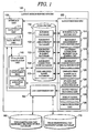
- Fig. 1 is a block diagram showing an embodiment of a layout design support system.
- a layout design support system 100 is constituted by an interface unit 110, a layout editing unit 120, a storage unit 130, an evaluation calculation unit 140, and a CAD conversion unit 150, all of which are realized on a computer.
- Each unit 110, 120, 130, 140, 150 will be described in detail below.
- the interface unit 110 is constituted by a data input unit 111 and a data output unit 112.
- the data input unit 111 is an input apparatus such as a mouse or keyboard for inputting various instructions and data into the computer in accordance with a user operation
- the data output unit 112 is an output apparatus such as a display or printer for outputting in display or other method, various data which includes data input through the data input unit 111, data stored in the storage unit 130, and results processed by the layout editing unit 120, evaluation calculation unit 140, and CAD conversion unit 150 to the user.
- the interface unit 110 is a part for performing information exchange between the computer and the user, and is typically known as a "user interface" or the like.
- the layout editing unit 120 serves as means for causing the interface unit 110 to display a layout design data editing screen, receiving an edit instruction input on the screen, and editing the layout design data in accordance with the edit instruction.
- the layout editing unit 120 uses classified data into five data types, namely building data, equipment arrangement data, equipment connection element data, equipment connection path data, and user-specified range data, and edits data belonging to each data type independently to generate layout design data.
- the "building data” relates to the base lines and arrangement of the buildings, while the “equipment arrangement data” relates to the arrangement of the equipments.
- the “equipment connection element data” and “equipment connection path data” are sub-types of “equipment connection data” relating to the physical connections between equipments.
- the “equipment connection element data” relates to the constitution of the physical connection elements (piping, cables, and so on) of the equipments, while the “equipment connection path data” relates to the constitution of auxiliary elements (racks, trenches, and so on) which form paths for the equipment connection elements.
- the "user-specified range data” relates to a range (total material amount range, CAD data conversion range, and so on) specified by the user for a particular purpose.
- the layout editing unit 120 comprises a building data editing unit 121, an equipment arrangement data editing unit 122, an equipment connection element data editing unit 123, an equipment connection path data editing unit 124, and a user-specified range data editing unit 125, each of which serves as an individual editing unit for editing data of one of the five data types, i.e. building data, equipment arrangement data, equipment connection element data, equipment connection path data, and user-specified range data, independently.
- the building data editing unit 121, equipment arrangement data editing unit 122, and equipment connection element data editing unit 123 are what characterized this embodiment, so the detail thereof is explained below, while the detailed explanation of the equipment connection path data editing unit 124 and user-specified range data editing unit 125 is omitted because the configuration thereof is the same as that of the Patent Document 1.
- the individual editing units 121 to 125 each comprise an editing control unit which causes the interface unit 110 to display an editing screen for editing data, and accepts various editing instruction from a user to edit data, and a depiction control unit which causes the interface unit 110 to display a depiction screen for depicting data, and depict the data edited by the editing control unit.
- the editing control unit displays an input/select/display field or operation image element relating to an editing subject item of the layout design data, accepts an edit instruction and data input corresponding to a user operation, and edits the layout design data in accordance with the accepted information.
- the depiction control unit depicts the edited layout design data on a depiction screen.
- an "operation image element” denotes an individual image element serving as an operation unit which performs input or selection in accordance with a user operation, such as an operation button, a cursor, an input window, and so on.
- the term "input/select/display field” or “select/display field” is a wide concept denoting a functional unit which performs input or selection and displays the content thereof in accordance with a user operation, and which includes an operation button, a cursor, an input window, and an item name display for realizing a specific function.
- the layout editing unit 120 further comprises an evaluation calculation activating unit 126, an output format switching unit 127, a display range modification unit 128, and a screen switching unit 129.
- the evaluation calculation activating unit 126 causes the evaluation calculation unit 140 to begin evaluation calculation process in accordance with an instruction input via the input/select/display field or operation image element displayed on the editing screen or depiction screen. A specific evaluation calculation process is described later.
- the output format switching unit 127 controls the CAD conversion unit 150 in accordance with an instruction input via the input/select/display field or operation image element displayed on the editing screen or depiction screen to switch the output format of the depiction screen to a two-dimensional CAD drawing or a three-dimensional CAD model.
- the display range modification unit 128, in accordance with an instruction input via the input/select/display field or operation image element displayed on the editing screen or depiction screen, switches the buildings and arrangement displayed on the depiction screen and enlarges or reduces the depiction screen through the editing control unit and depiction control unit of the individual editing units 121 to 125.
- this embodiment includes a mode in which the layout range of depiction screen is restricted in the vertical direction, so that the display range modification unit 128 contributes to the adjustment of the depiction screen in such case.
- the image switching unit 129 switches between the editing screen and depiction screen in accordance with an instruction input via the input/select/display field or operation image element displayed on the editing screen or depiction screen.
- the layout editing unit 120 is realized by the main memory of the computer, a specialized layout design editing program stored therein, a CPU controlled by the program, and so on.
- the storage unit 130 comprises a building database 131, an equipment arrangement database 132, an equipment connection element database 133, an equipment connection path database 134, and a user-specified range database 135 serving as databases for storing individually the editing results of the building data, equipment arrangement data, equipment connection element data, equipment connection path data, and user-specified range data edited by the individual editing units 121 to 125 of the layout editing unit 120.
- equipment specification equipment coordinates, size and angle are set for each equipment.
- equipment specification in addition to equipment name, piece numbers of pieces configuring the equipment.
- equipment specification besides the piece numbers, detailed equipment name and building name of the building where the equipment is provided, are set.
- Z coordinate in the vertical direction is set in addition to X coordinate and Y coordinate.
- the height equivalent to the length in the vertical direction is set in addition to the length and width on a horizontal plane.
- an equipment arrangement angle is set at a prescribed rotation angle, which is equivalent to a rotation angle when the longitudinal axis of an equipment is rotated about the vertical axis passing through the arrangement coordinate point of the equipment.
- connection name connection name of the equipment connection element
- equipment name of upstream and down stream connection destination equipments piece number and port of the equipments.
- the length direction on a horizontal plane is decided based on the arrangement coordinates and angle of the equipment, and each surface size of a rectangular parallelepiped is decided based on the equipment size, so that, as shown in Fig. 3 , a rectangular parallelepiped is simulated which is constituted by six surfaces of front and back surfaces at both ends in the length direction, right and left surfaces in the width direction, and top and bottom surfaces in the vertical direction.
- each surface configuring the equipment (black-filled circle in Fig. 3 ) is used as a representative point, which is equivalent to connection part for connecting to connection element such as piping and cable as described later.
- the representative points are displayed in two-dimension, but recognized in three-dimensional for evaluation calculation.
- Examples of the specific storage formats that may be used to store the layout design data in the various databases 131 to 135 of the storage unit 130 include a spreadsheet format, a database format, and a text file format.
- any storage format may be employed for the layout design data as long as the format, such as the data field name, is appropriate for the layout editing unit 120 and can be read by the layout editing unit 120.
- the storage unit 130 is realized by various types of computer memory, an auxiliary storage apparatus, and so on.
- the evaluation calculation unit 140 performs an evaluation calculation process, including calculation of a layout design data state value or a repeated optimization calculation, using a preset algorithm, and causes the interface unit to display the obtained calculation result on a screen.
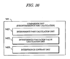
- the evaluation calculation unit 140 comprises a comparison unit 141 and an animation unit 142.
- the comparison unit 141 reads past layout design data stored in the storage unit 130 as past record data, performs an evaluation calculation on a plurality of layout design data including the past record data, and causes the interface unit 110 to display the calculation result on a screen in a comparative format such as a graph format.
- the animation unit 142 causes the interface unit 110 to perform continuous screen display of a layout diagram of log data relating to the layout design data output by the layout editing unit 120.
- the evaluation calculation unit 140 is realized by the main memory of the computer, a specialized evaluation calculation program stored therein, the CPU controlled by the program, and so on. Further, the program for realizing the evaluation calculation unit 140 may be an independent program or a part of the program for realizing the layout editing unit 120.
- the CAD conversion unit 150 uses data relating to a two-dimensional CAD equipment drawing symbol and data relating to a three-dimensional CAD equipment model to convert the layout design data into a two-dimensional CAD drawing or a three-dimensional CAD model, and causes the interface unit 110 to display the result on a screen.
- the CAD conversion unit 150 obtains the required CAD data from a two-dimensional CAD equipment drawing symbol database 160 and a three-dimensional CAD equipment model database 170, which are provided in advance on the outside of the layout design support system 100.
- CAD data may be prepared in advance within the layout design support system 100.
- the CAD conversion unit 150 is realized by the main memory of the computer, a specialized CAD conversion program stored in the main memory, the CPU controlled by the program, and so on. Further, the program for realizing the CAD conversion unit 150 may be an independent program or a part of the program for realizing the layout editing unit 120.
- the layout editing unit 120 is characterized by that a layout design process is performed with recognizing in terms of three-dimension the position relation inside a building.
- the building data editing unit 121, equipment arrangement data editing unit 122, and equipment connection element data editing unit 123, which each are notable for having such characteristics, are explained below.
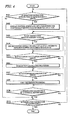
- FIG. 4 is a flowchart showing an outline of layout editing process performed by the layout design support system 100 according to this embodiment.
- operations of the interface unit 110, operation image elements displayed on the screen, and operations performed by a designer in relation thereto constitute typical interactive input/output process through the interface unit 110. Therefore, description relating to this typical interactive input/output process will hereafter be omitted where appropriate, and description will focus on the characteristic process serving as the main operations of the layout editing unit 120, evaluation calculation unit 140, CAD conversion unit 150, and so on.
- the five data types constituting the individual editing subjects are displayed on an editing screen by the layout editing unit 120, and when a selection instruction relating to a specific data type is input by a user and accepted by the layout editing unit 120 (YES in S401), the layout editing unit 120 causes the interface unit 110 to display the individual editing screen of this data type relating to the layout design of a target plant.
- the editing screen and depiction screen for individually editing data of the selected data type are displayed by the individual editing unit 121 to 125 of the selected data type through the interface unit 110 (S402).
- the individual editing unit 121 to 125 of the selected data type edits the layout design data in accordance with the edit instruction, transmits the obtained editing result to the depiction screen, where the result is reflected in the layout diagram, and stores the result in the database 131 to 135 of the selected data type (S404).
- the evaluation calculation unit 140 When an evaluation calculation instruction is input during layout editing (YES in S405), the evaluation calculation unit 140 is activated by the evaluation calculation activating unit 126 of the layout editing unit 120, and evaluation calculation process is performed by the evaluation calculation unit 140 (S406). In other words, the evaluation calculation unit 140 displays the control screen for evaluation calculation process, and in accordance with an instruction input onto the control screen, performs evaluation calculation process, including calculation of a layout design data state value or a repeated optimization calculation, using a preset algorithm. The obtained calculation result is then displayed on a screen.
- the evaluation calculation unit 140 uses the comparison unit 141 to read past layout design data stored in the storage unit 130 as past record data using the comparison unit 141, perform an evaluation calculation on a plurality of layout design data including the past record data, and display the calculation result on a screen in a comparative format such as a graph format.
- the animation unit 142 performs continuous screen display of a layout diagram of log data relating to the layout design data output by the layout editing unit 120.
- the output format switching unit 127 of the layout editing unit 120 controls the CAD conversion unit 150 to perform CAD conversion process.
- the depiction screen output format is switched to a two-dimensional CAD drawing or a three-dimensional CAD model by the CAD conversion unit 150 (S408).
- the layout editing unit 120 continues individual editing process of the selected data type (S403 to S408) until an instruction to terminate individual editing process of the selected data type is input (NO in S409).
- an individual editing process termination instruction is input (YES in S409) and a selection instruction relating to the next data type is input, individual editing process relating to the new data type is performed.
- Figs. 5A and 5B are views showing a functional configuration example of editing control units for building data in the building data editing unit 121, Fig. 5A showing a building base line data editing control unit 500a, and Fig. 5B showing an building arrangement data editing control unit 500b.
- the editing control units 500a and 500b each cause the interface unit 110 to display an editing screen for the building data, perform various display processes for supporting various operations on the displayed editing screen, and accept various inputs from a user to edit the building data.
- the building base line data editing control unit 500a so as to perform various display processes for supporting operations on a displayed editing screen for the building base line data, and accept various inputs to edit the building base line data, comprises a base line data editing select/display field 511 which displays an indication of a function for editing building base line data relating to the base line of the building, and allows the user to select the function as a switching destination function.
- the building base line data editing control unit 500a also comprises a base line name select/display field 512 which displays a base line name and allows the user to select the name or change into another name, a base line direction select/display field 513 for displaying and correcting the direction of a base line specified on the base line name select/display field 512, and a base line offset value select/display field 514 for displaying and correcting an offset position from the origin of the base line specified on the base line name select/display field 512.
- a base line name select/display field 512 which displays a base line name and allows the user to select the name or change into another name
- a base line direction select/display field 513 for displaying and correcting the direction of a base line specified on the base line name select/display field 512
- a base line offset value select/display field 514 for displaying and correcting an offset position from the origin of the base line specified on the base line name select/display field 512.
- the building base line data editing control unit 500a also comprises a base line piece number select/display field 515 which displays the piece number of a base line specified by the base line data editing select/display field 511 and changes the piece number into another number selected by the user.
- the base line piece number select/display field 515 displays a piece number, and accepts an input from the user, the base line piece number select/display field 515 set the piece number or change it into another number.
- the piece numbers used for the building arrangement data and the building base line data are the numbers given to the individual pieces which are defined within a building range or entire layout range where appropriate.
- the building arrangement data for example, it may be taken into account that a plurality of buildings each, which are provided within the entire layout range, are defined as building pieces, and that a piece number is set for each of the building pieces. It also may be taken into account that a single building is divided into a plurality of building pieces, and that a piece number is set for each of the building pieces which configures the single building.
- the building base line data it may be taken into account that a plurality of base lines each, which are disposed within a building range or the entire layout range, are defined as base line pieces, and that a piece number is set for each of the base line pieces. It also may be taken into account that the piece number of a building piece is set as a piece number for a base line which is included in the building piece. In any case of these, an building data editing process can be performed efficiently using such piece numbers.
- the building base line data editing control unit 500a further comprises, as units for correcting, adding, deleting, or moving a base line specified on the base line name select/display field 512 on the depiction screen, a base line correction unit 516, a base line addition unit 517, a base line deletion unit 518, and a base line movement unit 519, which display a correction button, a addition button, and a deletion button, and a movement button, respectively on the editing screen, and accept an input to perform various operations.
- the base line correction unit 516 when having accepted an correction input from the correction button, corrects the specified base line in accordance with the content set on the base line direction select/display field 513 and the base line offset value select/display field 514.
- the building base line data editing control unit 500a further comprises a base line update unit 520 which displays a update button on the editing screen, accepts an input to obtain data relating to the position and dimensions of the base line edited by the editing control unit 500a, and reflects these data in the building database 131 as a building base line data editing result.
- a base line update unit 520 which displays a update button on the editing screen, accepts an input to obtain data relating to the position and dimensions of the base line edited by the editing control unit 500a, and reflects these data in the building database 131 as a building base line data editing result.
- the building base line data editing control unit 500a further comprises a display range select/display field 521 which selects the entire layout range (entire site area) or the building range as the display range, and changes the display angle of the display range.
- the editing control unit 500a further comprises a vertical direction display range select/display field 522, allows the user to select as restriction values in Z direction the peak value and bottom value, and sets the display range in the vertical direction in accordance with input Z-direction range. Note that the display range select/display field 521 and vertical direction display range select/display field 522 are provided in common with the building arrangement data editing control unit 500b described below.
- the building arrangement data editing control unit 500b so as to perform various display processes for supporting operations on a displayed editing screen for the building arrangement data, and accept various inputs to edit the building arrangement data, comprises a building arrangement data editing select/display field 531 which displays an indication of a function for editing building arrangement data relating to the arrangement of the building, and allows the user to select the function as a switching destination function.
- the building arrangement data editing control unit 500b also comprises a building name select/display field 532 which displays a building name and allows the user to select the name or change into another name, a building arrangement select/display field 533 for displaying and correcting building arrangement information specified on the building name select/display field 532, and a building arrangement reference point select/display field 534 for showing whether a reference point of the building arrangement information displayed by the building arrangement select/display field 533 is at a minimum value or a maximum value of the arrangement, and correcting the reference point.
- a building name select/display field 532 which displays a building name and allows the user to select the name or change into another name
- a building arrangement select/display field 533 for displaying and correcting building arrangement information specified on the building name select/display field 532
- a building arrangement reference point select/display field 534 for showing whether a reference point of the building arrangement information displayed by the building arrangement select/display field 533 is at a minimum value or a maximum value of the arrangement
- the building arrangement data editing control unit 500b further comprises, as units for correcting, adding, deleting, or moving a building specified on the building name select/display field 532 on the depiction screen, a building correction unit 536, a building addition unit 537, and a building deletion unit 538, and a building movement unit 539, which display a correction button, a addition button, and a deletion button, and a movement button, respectively on the editing screen, and accept an input to perform various operations.
- the building correction unit 536 when having accepted an correction input from the correction button, corrects the specified building in accordance with the content set on the building arrangement select/display field 533 and the building arrangement reference point select/display field 534.
- the building arrangement data editing control unit 500b further comprises a building arrangement data update unit 540 which displays a update button on the editing screen, accepts an input to obtain data relating to the position and dimensions of the building edited by the editing control unit 500b and reflects these data in the building database 131 as a building arrangement data editing result.
- a building arrangement data update unit 540 which displays a update button on the editing screen, accepts an input to obtain data relating to the position and dimensions of the building edited by the editing control unit 500b and reflects these data in the building database 131 as a building arrangement data editing result.
- FIGS. 6A and 6B are views showing a functional configuration example of depiction control units for building data in the building data editing unit 121, Fig. 6A showing a building base line data depiction control unit 600a, and Fig. 6B showing an building arrangement data depiction control unit 600b.
- the depiction control units 600a and 600b each cause the interface unit 110 to display a depiction screen for the building data, perform various processes for depicting the building data on the displayed depiction screen.
- the building base line data depiction control unit 600a comprises a read unit 611 for reading an offset value and direction or the like of a base line for depiction use from the building database 131 of the storage unit 130.
- the building base line data depiction control unit 600a also comprises a display range decision unit 612 for deciding whether a building is set for the display range or not through the display range select/display field 521 of the editing control unit 500a.
- the depiction control unit 600a also comprises a base line decision unit 613a for deciding whether or not a base line read from the building database 131 through the read unit 611 is disposed within a building if the display range decision unit 612 has decided that the building is set for the display range.
- the depiction control unit 600a also comprises a depiction unit 614 for depicting on a depiction screen the base line layout design data generated by various processes of the editing control unit 500a.
- the depiction unit 614 depicts the base line layout design data on the depiction screen within the vertical display range (within defined by the peak and bottom values in Z direction) set by the vertical direction display range select/display field 522.
- the depiction control unit 600a comprises a selection decision unit 615 for deciding whether or not the layout-designed base line data corresponds to the base line specified by the base line data editing select/display field 511, and a display unit 616 for causing the interface unit 110 to actually display the base line on a depiction screen.
- the selection decision unit 615 has decided that the base line data corresponds to the specified base line
- the display unit 616 changes the display mode of the base line (for example, visually emphasized display by changing the color scheme).
- the base line data depiction control unit 600a has the configuration as described above, and the building arrangement data depiction control unit 600b has the same configuration as that of the depiction control unit 600a, except for the depicted data, which is not the base line data but the building data. Therefore, with regard to the configuration of the building arrangement data depiction control unit 600b, further explanation is omitted (See Fig. 6B ).
- base line display is performed in the following manner as a loop process (LOOP) executed in units of the base line records stored in the building database 131.
- LOOP loop process
- a record relating to each base line is read from the building database 131 of the storage unit 130 in record sequence by the read unit 611 of the depiction control unit 600a (S701), and then the building name registered in the base line record is read (S702). Whether the building range is specified as the display range is decided by the display range decision unit 612 (S703). When the building range is specified (YES in S703), whether the read base line is disposed within the specified building range is decided by the base line decision unit 613a (S704).
- the shape of the base line including a straight base line and label or the like is generated (S705) using the direction and offset value or the like of the read base line by the depiction unit 614.
- the shape of the base line is generated within the range defined by the peak and bottom values in the vertical direction.
- the selection decision unit 615 When the selection decision unit 615 has decided that the name of the base line corresponds to the base line name specified on the base line name select/display field 512 (YES in S706), the base line is displayed in a visually-emphasized manner, for example, on the depiction screen as described later, by the display unit 616 (S707).
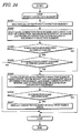
- FIG. 8 a flow of display process when the building data, which are stored in the building database 131, is read and a building layout is displayed on a depiction screen by the building data depiction control unit 600b, is explained below.
- building display is performed in the following manner as a loop process (LOOP) executed in units of the building records stored in the building database 131.
- LOOP loop process
- a record relating to each building is read from the building database 131 in record sequence by the read unit 611 of the depiction control unit 600b (S801), and then the building name registered in the building record is read (S802) Whether the building range is specified as the display range is decided by the display range decision unit 612 (S803). When the building range is specified (YES in S803), whether the read building is disposed within the specified building range is decided by the building decision unit 613b (SB04).
- the shape of the building is generated (S805) using the arrangement coordinates and reference point or the like by the depiction unit 614.
- the shape of the building is generated within the range defined by the peak and bottom values in the vertical direction.
- the display range decision unit 612 has decided that the building range is not specified as the display range (NO in S803), the shape of the building is generated as is by the depiction unit 614 (S805).
- the selection decision unit 615 When the selection decision unit 615 has decided that the name of the building corresponds to the building name specified by the building name select/display field 532 (YES in S806), the building is displayed in a visually-emphasized manner, for example, on the depiction screen as described later, by the display unit 616 (S807).
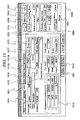
- Fig. 9 shows specific screen display example of an editing screen for base line data and building data.
- This editing screen 900 corresponds to various functions of the building base line data editing control unit 500a and the building arrangement data editing control unit 500b shown in Fig. 5 , and is used to switch between a plurality of other editing screens to be described below through the use of tabs 9101 displayed in the upper end portion.
- the tabs 9101 serve as means for realizing the functions of the screen switching unit 129.
- a base line data editing select/display field 9111, a base line name select/display field 9112, a base line direction select/display field 9113, a base line offset value select/display field 9114, a base line piece number select/display field 9115, and so on are disposed in the upper portion of the left-of-center part of the editing screen 900.
- These select/display fields 9111 to 9115 serve as a building base line data editing part, and correspond respectively to the select/display fields 511 to 515 shown in Fig. 5A , with which they share the final two digits of their respective reference numerals.
- a building arrangement data editing select/display field 9131, a building name select/display field 9132, a building arrangement select/display field 9133, a building arrangement reference point select/display field 9134, a building piece number select/display field 9135,and so on are disposed in the lower portion of the left-of-center part of the editing screen 900.
- These select/display fields 9131 to 9135 serve as a building arrangement data editing part, and correspond respectively to the select/display fields 531 to 535 shown in Fig. 5B , with which they share the final two digits of their respective reference numerals.
- buttons 9116 to 9120 corresponds respectively to the units 516 to 520 for editing base line data and the units 536 to 540 for editing building arrangement data shown in Figs. 5A and 5B .
- the building data can be edited in the following manner.
- an editing mode display is switched between a building base line data editing mode and a building arrangement data editing mode.
- the base line name select/display field 9112 reads the building base line data from the building database 131 and displays the base line names on a pull-down menu.
- the base line piece number select/display field 9115 displays the piece number of the building base line data
- the base line direction select/display field 9113 and base line offset value select/display field 9114 display the base line direction and base line offset value, respectively. This information can then be modified.
- a change button is depressed on the base line name select/display field 9112 while a base line name is displayed, the base line name can be modified.
- the modification content of the base line name select/display field 9112, base line direction select/display field 9113, and base line offset value select/display field 9114, and base line piece number select/display field 9115 is confirmed as modified data by pressing the correction button 9116.
- the addition button 9117, deletion button 9118, or movement button 9119 data relating to a new base line can be added, data relating to an unnecessary base line can be deleted, and a base line can be moved on a depiction screen.
- the redraw/data update button 9120 the base lines on the depiction screen can be redrawn in accordance with the building base line data edited on the editing screen 900, and the building database 131 can be updated.
- the building name select/display field 9132 reads the building arrangement data from the building database 131 and displays the building names on a pull-down menu.
- the building piece number select/display field 9135 displays the piece number corresponding to the selected building data.
- a selection input is accepted by the building arrangement reference point select/display field 9134 as to whether to edit the building arrangement using either the minimum coordinate point or the maximum coordinate point.
- the XYZ coordinates relating to the selected coordinate point are then displayed by the building arrangement select/display field 9133. This information can then be modified.
- a change button is depressed on the building name select/display field 9132 while a building name is displayed, the building name can be changed.
- the modification content of the building name select/display field 9132, building arrangement select/display field 9133, building arrangement reference point select/display field 9134, and building piece number select/display field 9135 is confirmed as modified data by pressing the correction button 9116.
- the addition button 9117, deletion button 9118, or movement button 9119 data relating to a new building can be added, data relating to an unnecessary building can be deleted, and a building can be moved on a depiction screen.
- the redraw/data update button 9120 the buildings on the depiction screen can be redrawn in accordance with the building arrangement data edited on the editing screen 900, and the building database 131 can be updated.
- Figs. 10A and 10B are views showing a functional configuration example of editing control units for equipment arrangement data in the equipment arrangement data editing unit 122, Fig. 10A showing an equipment arrangement data editing control unit 1000a, and Fig. 10B showing an equipment attribute data editing control unit 1000b.
- the editing control units 1000a and 1000b each cause the interface unit 110 to display an editing screen for the equipment arrangement data, perform various display processes for supporting various operations on the displayed editing screen, and accept various inputs from a user to edit the equipment arrangement data.
- the equipment arrangement data editing control unit 1000a so as to perform various display processes for supporting operations on a displayed editing screen for the equipment arrangement data, and accept various inputs to edit the equipment arrangement data, comprises an equipment name select/display field 1011 which displays an equipment name and allows the user to select the name or change into another name, and an equipment attribute editing select/display field 1012 which displays an indication of a function for editing equipment attribute data relating to the attributes of the equipment specified on the equipment name select/display field 1011, allows the user to select the function, and displays an editing screen for the equipment attribute data when the function is selected.
- an equipment name select/display field 1011 which displays an equipment name and allows the user to select the name or change into another name
- an equipment attribute editing select/display field 1012 which displays an indication of a function for editing equipment attribute data relating to the attributes of the equipment specified on the equipment name select/display field 1011, allows the user to select the function, and displays an editing screen for the equipment attribute data when the function is selected.
- the equipment arrangement data editing control unit 1000a further comprises an equipment arrangement select/display field 1013 for displaying and correcting the arrangement position and arrangement angle of the equipment specified on the equipment name select/display field 1011, an equipment shape/dimension select/display field 1014 for displaying and correcting the shape and dimensions of the equipment specified on the equipment name select/display field 1011, and a parent building select/display field 1015 for registering the name of the building to which the equipment specified on the equipment name select/display field 1011 belongs when the equipment belongs to a building.
- an equipment arrangement select/display field 1013 for displaying and correcting the arrangement position and arrangement angle of the equipment specified on the equipment name select/display field 1011
- an equipment shape/dimension select/display field 1014 for displaying and correcting the shape and dimensions of the equipment specified on the equipment name select/display field 1011
- a parent building select/display field 1015 for registering the name of the building to which the equipment specified on the equipment name select/display field 1011 belongs when the equipment belongs to
- the equipment arrangement data editing control unit 1000a also comprises an equipment piece number select/display field 1016 which displays the piece number of an equipment specified by the equipment name select/display field 1011 and changes the piece number into another number selected by the user.
- the equipment piece number select/display field 1016 displays a piece number as a part of equipment specification information including equipment name or the like, and accepts an input from the user, the equipment piece number select/display field 1016 set the piece number or change it into another number.
- the equipment piece number select/display field 1016 performs display switching into the piece number of another piece configuring the equipment.
- the equipment arrangement data editing control unit 1000a further comprises a CAD equipment select/display field 1017 for selecting the two-dimensional CAD equipment drawing symbol or three-dimensional equipment model associated with the equipment specified on the equipment name select/display field 1011, and displaying the symbol name or model name thereof.
- the CAD equipment select/display field 1017 serves as means for realizing the functions of the output format switching unit 127 on the editing screen, and by controlling the CAD conversion unit 150, a two-dimensional CAD equipment drawing symbol or a three-dimensional equipment model is displayed on the depiction screen.
- the equipment arrangement data editing control unit 1000a further comprises as units for correcting, adding, deleting, or moving an equipment specified on the equipment name select/display field 1011 on the depiction screen, an equipment correction unit 1018, an equipment addition unit 1019, an equipment deletion unit 1020, and an equipment movement unit 1021, which display a correction button, a addition button, and a deletion button, and a movement button, respectively on the editing screen, and accept an input to perform various operations.
- the equipment correction unit 1018 when having accepted a correction input from the correction button, corrects the specified equipment in accordance with the content set on the equipment attribute data editing control unit 1000b, the equipment arrangement select/display field 1013, the equipment shape/dimension select/display field 1014, and the parent building select/display field 1015.
- the equipment movement unit 1021 when having accepted an input from the movement button, moves the specified equipment on the depiction screen.
- each piece can be moved separately, or all pieces of the equipment can be moved in a lump.
- the equipment movement unit 1021 can move in a lump a group of equipments associated with a parent building specified by the parent building select/display field 1015. In other words, when a plurality of equipments are disposed in a single building which has a plurality of floors, and when the layout design requires the movement and rotation for each building, the equipment movement unit 1021 moves or rotates in a lump the equipment group associated with the building.
- an equipment connection element as described later is established, and thereby an equipment '1" of a building "A" is connected with an equipment "2" of another building "B", the equipment group of the building "A” can be moved while maintaining the connection relation.
- equipment group can be established not only by equipments disposed in a single building, but also by equipments having some relation with each other, so that, when a function of group selection is provided to the equipment attribute editing select/display field 1012, the equipments of a registered group can be moved or rotated in a lump.
- Such group is configured in accordance with, for example, system relation, design field relation, supplier relation, delivery date, and so on.
- the equipment arrangement data editing control unit 1000a further comprises an equipment arrangement data update unit 1022 which displays a update button on the editing screen, accepts an input to obtain data relating to the position and dimensions of the equipment edited by the editing control unit 1000a and reflects these data in the equipment arrangement database 132 as an equipment arrangement data editing result.
- an equipment arrangement data update unit 1022 which displays a update button on the editing screen, accepts an input to obtain data relating to the position and dimensions of the equipment edited by the editing control unit 1000a and reflects these data in the equipment arrangement database 132 as an equipment arrangement data editing result.
- the equipment arrangement data editing control unit 1000a further comprises a display range select/display field 1023 which selects the entire layout range (entire site area) or the building range as the display range, and changes the display angle of the display range.
- the editing control unit 1000a further comprises a vertical direction display range select/display field 1024, allows the user to select as restriction values in Z direction the peak value and bottom value, and sets the display range in the vertical direction in accordance with input Z-direction range.
- the equipment attribute data editing control unit 1000b so as to perform various display processes for supporting operations on a displayed editing screen for the equipment attribute data, and accept various inputs to edit the equipment attribute data, comprises a product information select/display field 1031 for displaying and correcting product information relating to the equipment specified on the equipment name select/display field 1011 such as the amount, delivery date, manufacturer, and cost.
- the equipment attribute data editing control unit 1000b further comprises an interference prohibition area information select/display field 1032 for displaying and correcting dimension information relating to the interference prohibition area, which is set with taking account of room space or restriction space according to rules for an equipment, regarding the equipment specified on the equipment name select/display field 1011, and a noise information select/display field 1033 for displaying and correcting dimension information relating to the area (referred to as "noise area” where appropriate below) affected by the noise of the equipment specified on the equipment name select/display field 1011, or information relating to the sound pressure level of the noise.
- an interference prohibition area information select/display field 1032 for displaying and correcting dimension information relating to the interference prohibition area, which is set with taking account of room space or restriction space according to rules for an equipment, regarding the equipment specified on the equipment name select/display field 1011
- a noise information select/display field 1033 for displaying and correcting dimension information relating to the area (referred to as "noise area" where appropriate below) affected by the noise
- the equipment attribute data editing control unit 1000b further comprises a constraint information select/display field 1034 for displaying and correcting constraint information required for optimization calculation of the equipment specified on the equipment name select/display field 1011.
- the equipment arrangement data update unit 1022 of the editing control unit 1000a accepts an input through the update button displayed on the editing screen by the interface unit 110, the results of the equipment arrangement data editing process performed by the editing control units 1000a and 1000b shown in Fig. 10 are stored in the equipment arrangement database 132 as updated equipment arrangement data.
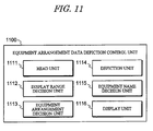
- Fig. 11 is a view showing a functional configuration example of depiction control unit 1100 for equipment arrangement data in the equipment arrangement data editing unit 122.
- the equipment arrangement data depiction control unit 1100 causes the interface unit 110 to display a depiction screen for the equipment arrangement data, performs various processes for depicting the equipment arrangement data on the displayed depiction screen.
- the equipment arrangement data depiction control unit 1100 comprises a read unit 1111 for reading a specification, arrangement coordinates, size, and so on regarding equipment arrangement for depiction use from the equipment arrangement database 132 of the storage unit 130.
- the equipment arrangement data depiction control unit 1100 also comprises a display range decision unit 1112 for deciding whether a building is set for the display range or not through the display range select/display field 1023 of the editing control unit 1000a.
- the depiction control unit 1100 also comprises an equipment arrangement decision unit 1113 for deciding whether or not an equipment read from the equipment arrangement database 132 through the read unit 1111 is disposed within a building if the display range decision unit 1112 has decided that the building is set for the display range.
- the depiction control unit 1100 also comprises a depiction unit 1114 for depicting on a depiction screen the equipment arrangement layout design data generated by various processes of the editing control units 1000a and 1000b.
- the depiction unit 1114 depicts the equipment arrangement layout design data on the depiction screen within the vertical display range (within defined by the peak and bottom values in Z direction) set by the vertical direction display range select/display field 1024.
- the depiction control unit 1100 comprises a equipment name decision unit 1115 for deciding whether or not the equipment name of an equipment depicted by the depiction unit 1114 corresponds to the equipment name specified by the equipment name select/display field 1011, and a display unit 1116 for causing the interface unit 110 to actually display the equipment on a depiction screen.
- the display unit 1116 changes the display mode of the equipment (for example, visually emphasized display by changing the color scheme).
- equipment display is performed in the following manner as a loop process (LOOP) executed in units of the equipment records stored in the equipment arrangement database 132.
- LOOP loop process
- a record relating to each equipment is read from the equipment arrangement database 132 of the storage unit 130 in record sequence by the read unit 1111 (S1201), and then the building name registered in the equipment record is read (S1202). Whether the building range is specified as the display range is decided by the display range decision unit 1112 (S1203). When the building range is specified (YES in S1203), whether the read equipment is disposed within the specified building range is decided by the equipment arrangement decision unit 1113 (S1204).
- the arrangement coordinates (white-filled circle in Fig. 3 ) and size are read from the equipment arrangement database 132, according to the arrangement coordinates, the length direction and width direction on a horizontal plane and height direction are decided using the arrangement coordinates as a reference point, so that a rectangular parallelepiped shape of the equipment is generated which has front and back surfaces at both ends in the length direction, right and left surfaces in the width direction, and top and bottom surfaces in the vertical direction.
- a rotation angle is stored as angle of the equipment, the longitudinal axis of an equipment is rotated about the vertical axis passing through the arrangement coordinate point of the equipment.
- the display range decision unit 1112 When the display range decision unit 1112 has decided that the building range is not specified as the display range (NO in S1203), the shape of the equipment is generated as is by the depiction unit 1114 (S1205).
- the equipment name decision unit 1115 When the equipment name decision unit 1115 has decided that the equipment name of the equipment corresponds to the equipment name specified by the equipment name select/display field 1011 (YES in S1206), the equipment is displayed in a visually-emphasized manner, for example, on a depiction screen by the display unit 1116.
- the area range when an interference prohibition area range or noise range area range is set which are required for study of the equipment, through the interference prohibition area information select/display field 1032 or noise information select/display field 1033, the area range also is displayed as a visible area together with the equipment by the display unit 1116.
- FIG. 13 shows a specific screen display example of an editing screen 1300 for equipment arrangement data.
- This editing screen 1300 corresponds to the equipment arrangement data editing control unit 1000a shown in Fig. 10A , and is used to switch between the aforementioned building data editing screen 900 and a plurality of other editing screens to be described below through the use of tabs 1301 displayed in the upper end portion.
- an equipment name select/display field 1311 As shown in Fig. 13 , an equipment name select/display field 1311, an equipment attribute editing select/display field 1312 (detail setting), an equipment arrangement select/display field 1313, an equipment shape/dimension select/display field 1314, a parent building select/display field 1315, an equipment piece number select/display field 1316, a CAD equipment select/display field 1317, and so on are disposed in the left-of-center part of the editing screen 1300.
- These select/display fields 1311 to 1317 correspond respectively to the select/display fields 1011 to 1017 shown in Fig. 10 , with which they share the final two digits of their respective reference numerals.
- Fig. 14 is a view showing a specific screen display example of an equipment attribute data editing screen 1400.
- This editing screen 1400 corresponds to the equipment attribute data editing control unit 1000b shown in Fig. 10B , and is constituted by a sub-screen which is switched to from the main editing screen 1300 of Fig. 13 or displayed in a new window.
- an attribute information select/display field 1401 is disposed on the editing screen 1400 for inputting various attribute information not provided on the main editing screen 1300.
- the attribute information select/display field 1401 corresponds to the product information select/display field 1031, noise information select/display field 1033 (only sound pressure level information of noise), and constraint information select/display field 1034 shown in Fig. 10B .
- Fig. 15A is a schematic view showing an interference prohibition area of an equipment
- Fig. 15B is a view showing a specific screen display example of an editing screen which is capable of editing both of interference prohibition area information and noise area information.
- an interference prohibition area information select/display field 1501 is shown on the editing screen 1500 of Fig. 15B .
- the interference prohibition area information select/display field 1501 is configured by a space type/rule select/display field 1511 for selecting a space type and rule name, and a numerical value setting select/display field 1512 for setting a numerical value for the selected space type.
- an interference prohibition area is selected by the space type/rule select/display field 1511 and the distance from each surface of a rectangular parallelepiped equipment is set, so that an interference prohibition area can be set in terms of three-dimension, as shown in Fig. 15A , and represented on a depiction screen.
- Fig. 15A is a view showing an interference prohibition area in terms of three-dimension.
- Such interference prohibition area is displayed on the real depiction screen in two-dimension, but can be represented in terms of three-dimension by setting the distance from the top surface and bottom surface of the area.
- the interference prohibition area is referred to as "tolerance”, which is used as meaning of a room space required for an equipment, and specifically, means a space for maintenance required for equipment maintenance, a space for bringing out an inner component, a space for accessing such as checking an instrument, or operating a valve or terminal box.
- a "rule" list is indicated in the space type/rule select/display field 1511, so that the interference area can be set for each rule.
- the space is set using rules defined according to the regulations.
- an equipment to be arranged may be of that does not come under the regulations and to which any rule is not applied, and in this case, in Fig. 15B , the check box of "use this rule" is turned to "off".
- the equipment arrangement data can be edited in the following manner.
- the equipment name select/display field 1311 on the editing screen 1300 reads the equipment arrangement data from the equipment arrangement database 132 and displays the equipment names on a pull-down menu. Subsequently, the equipment number select/display field 1316 displays the piece numbers on a pull-down menu which correspond to the equipment name specified by the equipment name select/display field 1311, and allows the user to select one of the piece numbers to set the selected piece number. Note that the initial value of the piece number is "1".
- the equipment arrangement select/display field 1313, equipment shape/dimension select/display field 1314, and parent building select/display field 1315 can display the arrangement coordinates and angle of the equipment, the shape and dimensions of the equipment, the name of the parent building, and so on, and allow the user to select for correcting the displayed items.
- the existence of a parent building indicates that when an equipment is disposed inside the parent building, the equipment moves integrally with the building.
- the color scheme of the equipments can be displayed and corrected on a color scheme select/display field 1312a associated with the equipment attribute editing select/display field 1312.
- the color scheme of the pieces can be changed as an equipment unit.
- a plurality of equipments can be registered as a group with group name on a group select/display field 1312b associated with the equipment attribute editing select/display field 1312.
- group select/display field 1312b when the group names of groups registered in the past are displayed on a pull-down menu and a group name of them are selected, the equipments of the group are highlighted on a depiction screen in a format such as display of a colored bold outline. In this case, the equipment group highlighted on the depiction screen can also be moved as a group unit.
- the importance, movability, cost, unit of cost, noise pressure level, vendor name, number of motors, number of anchor bolts, number of embedded metal fittings, and so on of the equipment can be displayed and selected to be corrected on the attribute information select/display field 1401 of the editing screen 1400.
- This information is useful when performing a simple tabulation of the amount of materials during editing of the user-specified range data.
- the CAD equipment select/display field 1317 of the editing screen 1300 converts the specified equipment into a two-dimensional CAD equipment drawing symbol or a three-dimensional equipment model in conjunction with the CAD conversion unit 150, and displays the result of the conversion.
- the CAD data may be obtained by pre-associating an equipment number used in the two-dimensional CAD equipment drawing symbol database 160 and the three-dimensional CAD equipment model database with an equipment name in the equipment arrangement data.
- the CAD data may be displayed by activating a separate application program to the application program for realizing the layout editing unit 120, or by developing a display program together with the program of the layout editing unit 120 such that the database is completely controlled.
- the designer can intuitively gain a comprehensive and clear overview of the layout design, and can avoid spatial recognition errors during subsequent layout editing work.
- the modification content of the equipment attribute data editing screen 1400, equipment arrangement select/display field 1313, equipment shape/dimension select/display field 1314, parent building select/display field 1315, equipment piece number select/display field 1316, and so on is confirmed as modified data by pressing the equipment correction button 1318.
- equipment addition button 1319 By pressing the equipment addition button 1319, equipment deletion button 1320, or equipment movement button 1321, data relating to a new equipment can be added, data relating to an unnecessary equipment can be deleted, and an equipment can be moved. Further, by pressing the redraw/equipment arrangement data update button 1322, in accordance with the equipment arrangement data edited on the editing screen 1300, the equipments can be redrawn on a depiction screen and the equipment arrangement database 132 can be updated.
- the minimum value and the maximum value in the vertical direction can be selected by the vertical direction display range select/display field 1324 of the editing screen 1300, equipments within a prescribed range in the vertical direction can be displayed. Namely, when the minimum and maximum value can be modified on the vertical direction display range select/display field 1324, the screen range to be depicted can be modified on the depiction screen described later. However, the layout in two-dimension is actually depicted on the depiction screen, so that modification of the value in the vertical direction gives no modification to the depiction image when the modified value is within the vertical direction display range.
- Fig. 17 shows a layout of the equipment arrangement data when a plurality of equipments are disposed on a first floor of a building.
- the depiction screen 1700 displays a building 1720 and a plurality of equipments 1730 within an entire layout range 1710.
- a name label 1741, an arrangement point 1742, an arrangement direction arrow 1743, a piece number 1744, an interference prohibition area range 1750, a noise area range 1760, and so on are displayed in a visually-emphasized manner.
- the interference prohibition area range 1750 is determined in consideration of equipment workability and maintainability.
- the interference prohibition area range 1750 may be displayed by inputting a distance from each of the six surfaces which configures the equipment.
- the noise area range 1760 may be displayed by calculating the difference between the sound pressure level of the equipment and the sound pressure level at the contour display boundary, and calculating the distance to the boundary sound pressure level from the sectional area of the equipment, for example.
- the interference prohibition area range and noise area range are merely examples of attribute information relating to the range of the equipment, and various other attribute information may be expressed similarly in the form of equipment ranges.
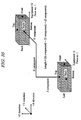
- FIG. 18 to 20 which give an example of a building with a plurality of floors
- Figs. 18 and 19 are schematic views for simulating the layout which is depicted on a depiction screen of the interface unit 110 by the depiction control unit 1100.
- a layout in two-dimension as shown in Fig. 20 is depicted.
- the first floor has a height of 0 meter and the equipments 11, 12, 13, and 14, are disposed on the floor.
- the equipment 14 is disposed on the first floor, but higher than other equipments and the upper part thereof passes through and projects above the second floor which has a height of 8 meters.
- the equipments 13 and 14 are cylinder shape tanks, while the other equipments are displayed in rectangular parallelepiped shapes.
- a depiction screen is generated by the depiction control unit 1100, as shown in Figs. 20A and 20B . That is, as shown in Fig.
- a layout is depicted in which the equipment 21, equipment 22, equipment 23, and equipment 14 are disposed.
- the equipment 14 is disposed on the first floor and projected above the second floor.
- a layout is depicted in which the equipment 11, equipment 12, equipment 13, and equipment 14 are disposed.
- Fig. 33 is a depiction screen example in consideration of the case in which the first floor equipment 14 has a height of not achieved the second floor, but a maintenance space which extends above the second floor is required for the equipment.
- an interference prohibition area is set as a room space (for example, maintenance space) extending above the second floor, in accordance with this information, the interference prohibition area is depicted within the display range by the depiction control unit 1100, even if the equipment body does not exist within the display range.
- the equipment outside the display range in the vertical direction is depicted with a specific color (stroke color, fill color) to remarkably indicate the difference by the depiction control unit 1100
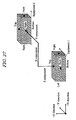
- Fig. 21A is a schematic view showing an equipment 1 configured by a plurality of rectangular parallelepiped pieces which correspond respectively to piece numbers 1 to 5.
- Fig. 21B is a depiction screen on which the equipment shown in Fig. 21A is actually displayed.
- a depiction screen actually depicted by the depiction control unit 1100 as shown in Fig. 21B , the equipment shown in Fig. 21A is represented in two-dimension and the arrangement of the pieces of piece numbers 1 to 5 is represented to be intuitively and comprehensively grasped. Note that piping or cables are to be connected with the piece of piece number 2, and this plan also is represented in two-dimension.
- each piece can be moved, rotated, or modified in size, separately, or can be moved or rotated as a single equipment 1 configured by combining the pieces.
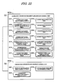
- Figs. 22A and 22B are views showing a functional configuration example of editing control units for equipment connection element data in the equipment connection element data editing unit 123, Fig. 22A showing an equipment connection element data editing control unit 2200a, and Fig. 22B showing an equipment connection attribute data editing control unit 2200b.
- the editing control units 2200a and 2200b each cause the interface unit 110 to display an editing screen for the equipment connection element data, perform various display processes for supporting various operations on the displayed editing screen, and accept various inputs from a user to edit the equipment connection element data.
- the equipment connection element data editing control unit 2200a comprises a connection name select/display field 2211 which displays a connection name and allows the user to select the name or change into another name, and a connection attribute editing select/display field 2212 which displays an indication of a function for editing connection attribute data relating to the attributes of the connection specified on the connection name select/display field 2211, allows the user to select the function, and displays an editing screen for the connection attribute data when the function is selected.
- the equipment connection element data editing control unit 2200a comprises a connection mode select/display field 2213 which displays and corrects the connection mode (piping, cable, or the like) of the connection specified on the connection name select/display field 2211, and a connection level select/display field 2214 which displays and corrects the connection level of the connection specified on the connection name select/display field 2211.
- the equipment connection element data editing control unit 2200a also comprises a connection destination equipment select/display field 2215 which displays and corrects the name of the upstream connection destination equipment and the connection port thereof, and the name of the downstream connection destination equipment and the connection port thereof, in relation to the connection specified on the connection name select/display field 2211, and an interference allowance/prohibition select/display field 2216 which allows the user to select whether an interference is allowed or not between the connection specified on the connection name select/display field 2211 and another connection.
- a connection destination equipment select/display field 2215 which displays and corrects the name of the upstream connection destination equipment and the connection port thereof, and the name of the downstream connection destination equipment and the connection port thereof, in relation to the connection specified on the connection name select/display field 2211
- an interference allowance/prohibition select/display field 2216 which allows the user to select whether an interference is allowed or not between the connection specified on the connection name select/display field 2211 and another connection.
- the equipment connection element data editing control unit 2200a also comprises a connection piece number select/display field 2217 which displays the piece numbers of the upstream connection destination equipment and down stream connection destination equipment, and sets the piece numbers when the user select it.
- the connection piece number select/display field 2217 can display the piece numbers of the upstream/downstream connection destination equipments in relation to the connection specified on the connection name select/display field 2211, and can set the piece numbers in accordance with an input from the user.
- the equipment connection element data editing control unit 2200a further comprises as units for correcting, adding, deleting, or moving an equipment connection element specified on the connection name select/display field 2211 on the depiction screen, a connection correction unit 2218, a connection addition unit 2219, a connection deletion unit 2220, and a connection movement unit 2221, which display a correction button, a addition button, and a deletion button, and a movement button, respectively on the editing screen, and accept an input to perform various operations.
- connection correction unit 2218 when having accepted a correction input from the correction button, corrects the specified equipment connection element in accordance with the content set on the connection attribute data editing control unit 2200b, the connection mode select/display field 2213, the connection level select/display field 2214, the connection destination equipment select/display field 2215, and the interference allowance/prohibition select/display field 2216.
- the connection attribute data editing control unit 2200b comprises a product information select/display field 2231 which displays and corrects product information relating to the connection specified on the connection name select/display field 2211 such as the sectional width, height, weight, and cost.
- the connection attribute data editing control unit 2200b further comprises a constraint information select/display field 2232 which displays and corrects constraint information required for optimization calculation of the connection specified on the connection name select/display field 2211.
- connection attribute data editing control unit 2200b also comprises a connection path name select/display field 2233 which displays and corrects the connection path name and control point (node) information of the connection specified on the connection name select/display field 2211.
- the equipment connection element data update unit 2222 of the editing control unit 2200a accepts an input through the update button displayed on the editing screen by the interface unit 110, the results of the equipment connection element data editing process performed by the editing control units 2200a and 2200b shown in Fig. 22 are stored in the equipment connection element database 133 as updated equipment connection element data.
- FIG. 23 is a view showing a functional configuration example of depiction control unit 2300 for equipment connection element data in the equipment connection element data editing unit 123.
- the equipment arrangement data depiction control unit 2300 causes the interface unit 110 to display a depiction screen for the equipment connection element data, performs various processes for depicting the equipment connection element data on the displayed depiction screen.
- the equipment connection element data depiction control unit 2300 comprises a read unit 2311 for reading a specification, arrangement coordinates, size, and so on regarding equipment arrangement for depiction use from the equipment connection element database 133 of the storage unit 130.
- the equipment connection element data depiction control unit 2300 also comprises a display range decision unit 2312 for deciding whether a building is set for the display range or not through the display range select/display field 2223 of the editing control unit 2200a.
- the depiction control unit 2300 also comprises an equipment connection element decision unit 2313 for deciding whether or not an equipment connection element read from the equipment connection element database 133 through the read unit 2311 is disposed within a building if the display range decision unit 2312 has decided that the building is set for the display range.
- the depiction control unit 2300 also comprises a depiction unit 2314 for depicting on a depiction screen the equipment connection element layout design data generated by various processes of the editing control units 2200a and 2200b.
- the depiction unit 2314 depicts the equipment connection element layout design data on the depiction screen within the vertical display range (within defined by the peak and bottom values in Z direction) set by the vertical direction display range select/display field 2224.
- FIG. 25 shows a specific screen display example of an editing screen 2500 for equipment arrangement data.
- This editing screen 2500 corresponds to the equipment connection element data editing control unit 2200a shown in Fig. 22A , and is used to switch between the aforementioned building data editing screen 900, equipment arrangement data editing screen 1300, and a plurality of other editing screens through the use of tabs 2501 displayed in the upper end portion.
- connection cross-section width, height, weight per unit length, cost per unit length, unit cost, and so on can be displayed and corrected on the cross-section information select/display field 2611 of the editing screen 2600. This information is useful when performing a simple tabulation of the amount of materials during editing of the user-specified range data.
- connection addition button 2519, connection deletion button 2520, or connection movement button 2521 data relating to a new equipment connection element can be added, data relating to an unnecessary equipment connection element can be deleted, and an equipment connection element can be moved.
- the redraw/equipment connection element data update button 2522 the equipment connection element on the depiction screen can be redrawn in accordance with the equipment connection element data edited on the editing screen 2500, and the equipment connection element database 133 can be updated.
- Figs. 29 to 33 give an example of a building with a plurality of floors.
- Figs. 29 to 33 are screen examples in which an equipment connection element is depicted to connect between the equipments on the depiction screen examples for equipment arrangement data shown in Figs. 18 to 20 .
- Fig. 32A is a depiction screen in which the equipment 11 of the connection starting side disposed on the first floor, is simulated on the second floor having a height of 6 to 10 meters shown in Fig. 31A .
- Fig. 32B is a depiction screen in which the equipment 23 of the connection ending side disposed on the second floor, is simulated on the first floor having a height of 0 to 5 meters shown in Fig. 31B .
- the depiction control unit 2300 can depict a connection destination equipment within a display range even if the equipment is disposed outside the display range which is set by the vertical direction display range select/display field 2224 of the editing control unit 2200a, in relation to another equipment which is connected with the connection destination equipment and disposed in one building together. That is, the equipment 11 connected with the equipment 23 is represented in Fig. 32A , and the equipment 23 connected with the equipment 11 is represented in Fig. 32B , even if the equipment is disposed outside the vertical display range set by the vertical direction display range select/display field 2224.
- the cost contrast unit 1413 contrasts the evaluation values based on the costs of each layout design data, and outputs the contrast result to the interface unit 110 through the animation unit 142 or the like. Further, the contrast result is stored in a file for each set range. Note that the distance calculation unit 1411 can make not only a calculation using XYZ components but also a calculation using merely XY components. In the latter case, position relation can be simply grasped from XY components.
- the comparison unit 141 comprises an interference part calculation unit 1421 which in relation to each layout design data of a past record data set, calculates the area of an interference part generated between equipments in two-dimension (including the area of an interference part generated between an equipment and an interference prohibition area such as room space, hereinafter the same as this), or the volume of an interference part generated between equipments in three-dimension (including the volume of an interference part generated between an equipment and an interference prohibition area such as room space, hereinafter the same as this).
- the comparison unit 141 also comprises an interference evaluation value calculation unit 1422 which adds the area or volume of an interference part between equipments calculated by the interference part calculation unit 1421 for each layout design data, to calculate as an evaluation value the total area or total volume of the interference part for each layout design data.
- the comparison unit 141 further comprises an interference contrast unit 1423 for contrasting the evaluation value for each layout design data calculated by the interference evaluation value calculation unit 1422.
- Fig. 38 is a schematic view showing the volume of an interference part between equipments when layout design data is recognized in three-dimension.
- the same process is performed as the case of calculation in two-dimension, except for calculating the volume of an interference part between equipments, so an explanation for this case is omitted.
- the interference part calculation unit 1421 converts the external shape of an equipment into a rectangular parallelepiped shape to calculate the volume of an interference part between the equipment and another equipment when the equipment has a cylinder shape.
- connections between equipments can be recognized in three-dimension, and so that, for example, evaluation calculation can be performed which calculates the total length and cost of piping and cables passing through boundary between floors.
- interference space between equipments can be recognized in three-dimension, so that interference space inside and outside a building can be calculated as an evaluation value in either case of two-dimension base and three-dimension base.
- an evaluation value of a layout having been designed can be calculated in terms of three-dimension, so that a plurality of layout candidates can be compared with each other using results of evaluation calculation according to the same standard, and a more superior layout candidate can be selected as a layout. Therefore, the present invention is suitable for design review duties of layout design.
Abstract
Description
- This application is based upon and claims the benefit of priority from Japanese Patent Application No.
2009-107935, filed April 27, 2009 - Embodiments described herein relate generally to a technique for supporting a layout design process which includes the arrangement of a building and a plurality of equipments within a layout range space of a plant and connections between the equipments, using a computer.
- In general, layout design of various types of plant facilities, such as chemical plants and electric power plants for generating thermal power, nuclear power, hydroelectric power, and so on, is performed on a plant design enterprise side to decide, for example, the arrangement of buildings, equipments, piping, cables, and so on. This layout design process is performed such that the process fits various conditions relating to the design content and various professional conditions. As a technique relating to such layout design process, in general, a layout design support system is used, which has a unit that can edit an equipment element and equipment connection element in two-dimension or three-dimension.
- For example, a technique exists, in which a screen for editing layout design data is displayed, and building data, equipment arrangement data, equipment connection element data, equipment connection path data, and use-specified range data, which are of five data types classified from layout design data, are edited individually and separately.
- In addition, a technique exists, in which various design conditions and objective conditions are set and an optimization calculation is performed in accordance with such conditions to design a layout of equipment arrangement.
- In addition, a technique exists, in which equipments, piping, and so on, for which a space has been set in advance with taking account of dismantlement and installation, are provided at equipment arrangement positions in a reference coordinate system in accordance with a prescribed arrangement rule with taking account of past data.
- In addition, a technique exists, in which efficiency of working processes for various equipments and piping is evaluated to decide the working content based on the evaluation result, and a technique exists, in which an automatic layout system has a unit performing a three-dimensional display process and generate a design route automatically.
- In addition, a technique exists, in which the influence of design is evaluated and the influence level can be checked, a technique exists, in which equipments, piping, and so on, are evaluated in advance for each arrangement and provided in the order of priority in accordance with the evaluation result, and a technique exists, in which an arrangement view is divided and a layout is displayed with referring to the divided arrangement view per unit.
- In addition, a technique exists, in which a layout data is displayed using actions of a human model represented in three-dimension, and a technique exists, in which building data is represented to search an optimum route.
- The conventional techniques as described above, for example, provide a system for supporting a layout design process which can intuitively and comprehensively grasp by displaying in two-dimension a concrete route designed with taking account of various conditions. However, this technique can not represent a detailed configuration of equipments, and can not recognize connections between equipments in three-dimension.
- The conventional techniques as described above, for example, show a system for supporting a layout design process. However, these techniques provide no system for supporting a layout design process which can intuitively and comprehensively grasp by displaying in two-dimension a concrete route designed with taking account of various conditions. In
Patent Documents 2 to 10, a three-dimensional display process is performed, but there is disclosed no technique for handling a detailed configuration of equipments and connections and arrangement space thereof in three-dimension. -
-
Fig. 1 is a block diagram showing an embodiment of a layout design support system; -
Fig. 2 is a view showing a structure example of equipment arrangement data stored in a storage unit; -
Fig. 3 is a conceptual view showing an image of equipment data recognized by a layout design support system; -
Fig. 4 is a flowchart showing an outline of layout editing process performed by a layout design support system; -
Figs. 5A and 5B are views showing a functional configuration example of an editing control unit for building data in a building data editing unit,Fig. 5A showing an editing control unit for building base line data, andFig. 5B showing an editing control unit for building arrangement data; -
Figs. 6A and 6B are views showing a functional configuration example of a depiction control unit for building data in a building data editing unit,Fig. 6A showing a depiction control unit for building base line data, andFig. 6B showing a depiction control unit for building arrangement data; -
Fig. 7 is a flowchart showing a flow of layout design process when base line data stored in building database, is read and a base line is depicted on a depiction screen; -
Fig. 8 is a flowchart showing a flow of layout design process when building arrangement data stored in building database, is read and a building is depicted on a depiction screen; -
Fig. 9 is a view showing a specific screen display example of an editing screen for building data in a building data editing unit; -
Figs. 10A and 10B are views showing a functional configuration example of an editing control unit for equipment arrangement data in an equipment arrangement data editing unit,Fig. 10A showing an editing control unit for equipment arrangement data, andFig. 10B showing an editing control unit for equipment attribute data; -
Fig. 11 is a view showing a functional configuration example of a depiction control unit for equipment arrangement data in an equipment arrangement data editing unit; -
Fig. 12 is a flowchart showing a flow of layout design process when equipment arrangement data stored in equipment arrangement database, is read and an equipment is depicted on a depiction screen; -
Fig. 13 is a view showing a specific screen display example of an editing screen for equipment arrangement data in an equipment arrangement data editing unit; -
Fig. 14 is a view showing a specific screen display example of an editing screen for equipment attribute data in an equipment arrangement data editing unit; -
Figs. 15A and15B are views showing an interference prohibition area information editing process performed by an equipment arrangement data editing unit,Fig. 15A being a schematic view showing an interference prohibition area for an equipment, andFig. 15B being a view showing a specific screen display example of an editing screen for an interference prohibition area information; -
Fig. 16 is a schematic view showing a process of equipment movement unit in an equipment arrangement data editing unit; -
Fig. 17 is a view showing a specific screen display example (building with a single floor) of a depiction screen for equipment arrangement data in an equipment arrangement data editing unit; -
Fig. 18 is a schematic view showing a layout (building with a plurality of floors) having been depicted by an equipment arrangement data editing unit; -
Fig. 19 is a schematic view showing a layout (building with a plurality of floors) having been depicted by an equipment arrangement data editing unit; -
Fig. 20 is a view showing a specific screen display example (building with a plurality of floors) of a depiction screen for equipment arrangement data in an equipment arrangement data editing unit; -
Figs. 21A and 21B are views showing a process when displaying an equipment by an equipment arrangement data editing unit,Fig. 21A being a schematic view showing an equipment configured from a plurality of pieces, andFig. 21B being a view showing a specific screen display example of a depiction screen for an equipment arrangement data; -
Figs. 22A and 22B are views showing a functional configuration example of an editing control unit for equipment connection element data in an equipment connection element data editing unit,Fig. 22A showing an editing control unit for equipment connection element data, andFig. 22B showing an editing control unit for connection attribute data; -
Fig. 23 is a view showing a functional configuration example of a depiction control unit for equipment connection element data in an equipment connection element data editing unit; -
Fig. 24 is a flowchart showing a flow of layout design process when equipment connection element data stored in equipment connection element database, is read and an equipment connection element is depicted on a depiction screen; -
Fig. 25 is a view showing a specific screen display example of an editing screen for equipment connection element data in an equipment connection element data editing unit; -
Fig. 26 is a view showing a specific screen display example of an editing screen for connection attribute data in an equipment connection element data editing unit; -
Fig. 27 is a schematic view showing an equipment connection element (display using XYZ components) having been depicted by an equipment connection element data editing unit; -
Fig. 28 is a view showing a specific screen display example (equipment connection element between equipments) of a depiction screen for equipment connection element data in an equipment connection element data editing unit; -
Fig. 29 is a schematic view showing an equipment connection element (building with a plurality of floors) having been depicted by an equipment connection element data editing unit; -
Fig. 30 is a schematic view showing an equipment connection element (building with a plurality of floors) having been depicted by an equipment connection element data editing unit; -
Fig. 31 is a view showing a specific screen display example (building with a plurality of floors) of a depiction screen for equipment connection element data in an equipment connection element data editing unit; -
Fig. 32 is a view showing a specific screen display example (display of a connection destination equipment outside a display range) of a depiction screen for equipment connection element data in an equipment connection element data editing unit; -
Fig. 33 is a view showing a specific screen display example (display of an interference prohibition area inside a display range) of a depiction screen for equipment connection element data in an equipment connection element data editing unit; -
Fig. 34 is a view showing a functional configuration example of a comparison unit (for cost calculation) in an evaluation calculation unit; -
Fig. 35 is a schematic view showing a cost calculation process of a comparison unit (for cost calculation) in an evaluation calculation unit; -
Fig. 36 is a view showing a functional configuration example of a comparison unit (for interference part calculation) in an evaluation calculation unit; -
Fig. 37 is a schematic view showing a cost calculation process of a comparison unit (for calculating the area of interference part) in an evaluation calculation unit; and -
Fig. 38 is a schematic view showing a cost calculation process of a comparison unit (for calculating the volume of interference part) in an evaluation calculation unit. - In general, according to one embodiment, a layout design support system has a layout editing unit which edits equipment arrangement data, equipment connection element data and the other data, and depicts the edited data, and a storage unit which storage such data. The storage unit stores equipment arrangement data that includes not only equipment specification data, and arrangement coordinate data and size data of each equipment, but also piece number of each piece configuring the equipment, and stores equipment connection element data that includes connection name, equipment name of upstream and downstream connection destination equipments, piece number and port of the equipments. The layout editing unit edits the equipment arrangement data or equipment connection element data at the level of the piece in accordance with an accepted edit instruction.
- An outline of a system configuration of this embodiment is explained below, referring to
Fig. 1 . Here,Fig. 1 is a block diagram showing an embodiment of a layout design support system. - As shown in
Fig. 1 , a layoutdesign support system 100 according to this embodiment is constituted by aninterface unit 110, alayout editing unit 120, astorage unit 130, anevaluation calculation unit 140, and aCAD conversion unit 150, all of which are realized on a computer. Eachunit - The
interface unit 110 is constituted by adata input unit 111 and adata output unit 112. Here, thedata input unit 111 is an input apparatus such as a mouse or keyboard for inputting various instructions and data into the computer in accordance with a user operation, and thedata output unit 112 is an output apparatus such as a display or printer for outputting in display or other method, various data which includes data input through thedata input unit 111, data stored in thestorage unit 130, and results processed by thelayout editing unit 120,evaluation calculation unit 140, andCAD conversion unit 150 to the user. In other words, theinterface unit 110 is a part for performing information exchange between the computer and the user, and is typically known as a "user interface" or the like. - The
layout editing unit 120 serves as means for causing theinterface unit 110 to display a layout design data editing screen, receiving an edit instruction input on the screen, and editing the layout design data in accordance with the edit instruction. In this embodiment, thelayout editing unit 120 uses classified data into five data types, namely building data, equipment arrangement data, equipment connection element data, equipment connection path data, and user-specified range data, and edits data belonging to each data type independently to generate layout design data. - Note that the "building data" relates to the base lines and arrangement of the buildings, while the "equipment arrangement data" relates to the arrangement of the equipments. The "equipment connection element data" and "equipment connection path data" are sub-types of "equipment connection data" relating to the physical connections between equipments. The "equipment connection element data" relates to the constitution of the physical connection elements (piping, cables, and so on) of the equipments, while the "equipment connection path data" relates to the constitution of auxiliary elements (racks, trenches, and so on) which form paths for the equipment connection elements. The "user-specified range data" relates to a range (total material amount range, CAD data conversion range, and so on) specified by the user for a particular purpose.
- Here, the
layout editing unit 120 comprises a buildingdata editing unit 121, an equipment arrangementdata editing unit 122, an equipment connection elementdata editing unit 123, an equipment connection pathdata editing unit 124, and a user-specified rangedata editing unit 125, each of which serves as an individual editing unit for editing data of one of the five data types, i.e. building data, equipment arrangement data, equipment connection element data, equipment connection path data, and user-specified range data, independently. Among these units, the buildingdata editing unit 121, equipment arrangementdata editing unit 122, and equipment connection elementdata editing unit 123, are what characterized this embodiment, so the detail thereof is explained below, while the detailed explanation of the equipment connection pathdata editing unit 124 and user-specified rangedata editing unit 125 is omitted because the configuration thereof is the same as that of thePatent Document 1. - Note that the
individual editing units 121 to 125 each comprise an editing control unit which causes theinterface unit 110 to display an editing screen for editing data, and accepts various editing instruction from a user to edit data, and a depiction control unit which causes theinterface unit 110 to display a depiction screen for depicting data, and depict the data edited by the editing control unit. In other words, the editing control unit displays an input/select/display field or operation image element relating to an editing subject item of the layout design data, accepts an edit instruction and data input corresponding to a user operation, and edits the layout design data in accordance with the accepted information. Subsequently, the depiction control unit depicts the edited layout design data on a depiction screen. - Note that in this specification, an "operation image element" denotes an individual image element serving as an operation unit which performs input or selection in accordance with a user operation, such as an operation button, a cursor, an input window, and so on. Further, the term "input/select/display field" or "select/display field" is a wide concept denoting a functional unit which performs input or selection and displays the content thereof in accordance with a user operation, and which includes an operation button, a cursor, an input window, and an item name display for realizing a specific function.
- The
layout editing unit 120 further comprises an evaluationcalculation activating unit 126, an outputformat switching unit 127, a displayrange modification unit 128, and ascreen switching unit 129. Here, the evaluationcalculation activating unit 126 causes theevaluation calculation unit 140 to begin evaluation calculation process in accordance with an instruction input via the input/select/display field or operation image element displayed on the editing screen or depiction screen. A specific evaluation calculation process is described later. - The output
format switching unit 127 controls theCAD conversion unit 150 in accordance with an instruction input via the input/select/display field or operation image element displayed on the editing screen or depiction screen to switch the output format of the depiction screen to a two-dimensional CAD drawing or a three-dimensional CAD model. - The display
range modification unit 128, in accordance with an instruction input via the input/select/display field or operation image element displayed on the editing screen or depiction screen, switches the buildings and arrangement displayed on the depiction screen and enlarges or reduces the depiction screen through the editing control unit and depiction control unit of theindividual editing units 121 to 125. As described later, this embodiment includes a mode in which the layout range of depiction screen is restricted in the vertical direction, so that the displayrange modification unit 128 contributes to the adjustment of the depiction screen in such case. - The
image switching unit 129 switches between the editing screen and depiction screen in accordance with an instruction input via the input/select/display field or operation image element displayed on the editing screen or depiction screen. - Note that specifically, the
layout editing unit 120 is realized by the main memory of the computer, a specialized layout design editing program stored therein, a CPU controlled by the program, and so on. - The
storage unit 130 comprises abuilding database 131, anequipment arrangement database 132, an equipmentconnection element database 133, an equipmentconnection path database 134, and a user-specifiedrange database 135 serving as databases for storing individually the editing results of the building data, equipment arrangement data, equipment connection element data, equipment connection path data, and user-specified range data edited by theindividual editing units 121 to 125 of thelayout editing unit 120. - In detail, for example, in the
equipment arrangement database 132 of this embodiment, as shown inFig. 2 , equipment specification, equipment coordinates, size and angle are set for each equipment. In more detail, as the equipment specification, in addition to equipment name, piece numbers of pieces configuring the equipment. Further, as the equipment specification, besides the piece numbers, detailed equipment name and building name of the building where the equipment is provided, are set. - As the equipment arrangement coordinates, Z coordinate in the vertical direction is set in addition to X coordinate and Y coordinate. As the equipment size, the height equivalent to the length in the vertical direction is set in addition to the length and width on a horizontal plane. As the angle, an equipment arrangement angle is set at a prescribed rotation angle, which is equivalent to a rotation angle when the longitudinal axis of an equipment is rotated about the vertical axis passing through the arrangement coordinate point of the equipment.
- In addition, in the equipment
connection element database 133, connection name, connection name of the equipment connection element, equipment name of upstream and down stream connection destination equipments, piece number and port of the equipments. - Here, a process is explained below, in which data such as the equipment specification and arrangement coordinate are read from the
equipment arrangement database 132, and used for generating an equipment image, referring toFig. 3 . In more detail, the arrangement coordinates (white-filled circle inFig. 3 ) and size are read from theequipment arrangement database 132, so that an equipment image as shown inFig. 3 is simulated which is displayed in two-dimensional, but recognized as a rectangular parallelepiped in three-dimensional in terms of data. - In more detail, the length direction on a horizontal plane is decided based on the arrangement coordinates and angle of the equipment, and each surface size of a rectangular parallelepiped is decided based on the equipment size, so that, as shown in
Fig. 3 , a rectangular parallelepiped is simulated which is constituted by six surfaces of front and back surfaces at both ends in the length direction, right and left surfaces in the width direction, and top and bottom surfaces in the vertical direction. - Note that the center of each surface configuring the equipment (black-filled circle in
Fig. 3 ) is used as a representative point, which is equivalent to connection part for connecting to connection element such as piping and cable as described later. The representative points are displayed in two-dimension, but recognized in three-dimensional for evaluation calculation. - Examples of the specific storage formats that may be used to store the layout design data in the
various databases 131 to 135 of thestorage unit 130 include a spreadsheet format, a database format, and a text file format. In other words, any storage format may be employed for the layout design data as long as the format, such as the data field name, is appropriate for thelayout editing unit 120 and can be read by thelayout editing unit 120. - Note that the
storage unit 130 is realized by various types of computer memory, an auxiliary storage apparatus, and so on. - The
evaluation calculation unit 140 performs an evaluation calculation process, including calculation of a layout design data state value or a repeated optimization calculation, using a preset algorithm, and causes the interface unit to display the obtained calculation result on a screen. Theevaluation calculation unit 140 comprises acomparison unit 141 and ananimation unit 142. - Here, the
comparison unit 141 reads past layout design data stored in thestorage unit 130 as past record data, performs an evaluation calculation on a plurality of layout design data including the past record data, and causes theinterface unit 110 to display the calculation result on a screen in a comparative format such as a graph format. Theanimation unit 142 causes theinterface unit 110 to perform continuous screen display of a layout diagram of log data relating to the layout design data output by thelayout editing unit 120. - Specifically, the
evaluation calculation unit 140 is realized by the main memory of the computer, a specialized evaluation calculation program stored therein, the CPU controlled by the program, and so on. Further, the program for realizing theevaluation calculation unit 140 may be an independent program or a part of the program for realizing thelayout editing unit 120. - The
CAD conversion unit 150 uses data relating to a two-dimensional CAD equipment drawing symbol and data relating to a three-dimensional CAD equipment model to convert the layout design data into a two-dimensional CAD drawing or a three-dimensional CAD model, and causes theinterface unit 110 to display the result on a screen. In this embodiment, theCAD conversion unit 150 obtains the required CAD data from a two-dimensional CAD equipmentdrawing symbol database 160 and a three-dimensional CADequipment model database 170, which are provided in advance on the outside of the layoutdesign support system 100. Alternatively, CAD data may be prepared in advance within the layoutdesign support system 100. - Specifically, the
CAD conversion unit 150 is realized by the main memory of the computer, a specialized CAD conversion program stored in the main memory, the CPU controlled by the program, and so on. Further, the program for realizing theCAD conversion unit 150 may be an independent program or a part of the program for realizing thelayout editing unit 120. - The
layout editing unit 120 according to this embodiment is characterized by that a layout design process is performed with recognizing in terms of three-dimension the position relation inside a building. The buildingdata editing unit 121, equipment arrangementdata editing unit 122, and equipment connection elementdata editing unit 123, which each are notable for having such characteristics, are explained below. - First, an outline of a layout editing process performed by the
layout editing unit 120 is explained, referring toFig. 4 . Here,Fig. 4 is a flowchart showing an outline of layout editing process performed by the layoutdesign support system 100 according to this embodiment. Note that operations of theinterface unit 110, operation image elements displayed on the screen, and operations performed by a designer in relation thereto constitute typical interactive input/output process through theinterface unit 110. Therefore, description relating to this typical interactive input/output process will hereafter be omitted where appropriate, and description will focus on the characteristic process serving as the main operations of thelayout editing unit 120,evaluation calculation unit 140,CAD conversion unit 150, and so on. - As shown in
Fig. 4 , in layout editing process, the five data types constituting the individual editing subjects are displayed on an editing screen by thelayout editing unit 120, and when a selection instruction relating to a specific data type is input by a user and accepted by the layout editing unit 120 (YES in S401), thelayout editing unit 120 causes theinterface unit 110 to display the individual editing screen of this data type relating to the layout design of a target plant. In other words, the editing screen and depiction screen for individually editing data of the selected data type are displayed by theindividual editing unit 121 to 125 of the selected data type through the interface unit 110 (S402). - When an edit instruction is input on the displayed editing screen by the user and accepted by the layout editing unit 120 (YES in S403), the
individual editing unit 121 to 125 of the selected data type edits the layout design data in accordance with the edit instruction, transmits the obtained editing result to the depiction screen, where the result is reflected in the layout diagram, and stores the result in thedatabase 131 to 135 of the selected data type (S404). - When an evaluation calculation instruction is input during layout editing (YES in S405), the
evaluation calculation unit 140 is activated by the evaluationcalculation activating unit 126 of thelayout editing unit 120, and evaluation calculation process is performed by the evaluation calculation unit 140 (S406). In other words, theevaluation calculation unit 140 displays the control screen for evaluation calculation process, and in accordance with an instruction input onto the control screen, performs evaluation calculation process, including calculation of a layout design data state value or a repeated optimization calculation, using a preset algorithm. The obtained calculation result is then displayed on a screen. - Specifically, when a comparison instruction is input on the evaluation calculation process control screen, for example, the
evaluation calculation unit 140 uses thecomparison unit 141 to read past layout design data stored in thestorage unit 130 as past record data using thecomparison unit 141, perform an evaluation calculation on a plurality of layout design data including the past record data, and display the calculation result on a screen in a comparative format such as a graph format. When a progress instruction is input, theanimation unit 142 performs continuous screen display of a layout diagram of log data relating to the layout design data output by thelayout editing unit 120. - When a CAD conversion instruction is input during layout editing (YES in S407), the output
format switching unit 127 of thelayout editing unit 120 controls theCAD conversion unit 150 to perform CAD conversion process. In other words, the depiction screen output format is switched to a two-dimensional CAD drawing or a three-dimensional CAD model by the CAD conversion unit 150 (S408). - Although not shown in
Fig. 4 , when a display range modification instruction or a screen switching instruction is input during layout editing, display modification or screen switching is performed by the displayrange modification unit 128 or thescreen switching unit 129 of thelayout editing unit 120. - The
layout editing unit 120 continues individual editing process of the selected data type (S403 to S408) until an instruction to terminate individual editing process of the selected data type is input (NO in S409). When an individual editing process termination instruction is input (YES in S409) and a selection instruction relating to the next data type is input, individual editing process relating to the new data type is performed. - Finally, when an editing termination instruction is input (YES in S410) following an individual editing process termination instruction (YES in S409), the
layout editing unit 120 terminates the series of layout editing process. - The layout editing process described above, which is performed by the layout design support system according to this embodiment, will now be described in further detail.
-
Figs. 5A and 5B are views showing a functional configuration example of editing control units for building data in the buildingdata editing unit 121,Fig. 5A showing a building base line dataediting control unit 500a, andFig. 5B showing an building arrangement data editingcontrol unit 500b. Theediting control units interface unit 110 to display an editing screen for the building data, perform various display processes for supporting various operations on the displayed editing screen, and accept various inputs from a user to edit the building data. - As shown in
Fig. 5A , the building base line dataediting control unit 500a, so as to perform various display processes for supporting operations on a displayed editing screen for the building base line data, and accept various inputs to edit the building base line data, comprises a base line data editing select/display field 511 which displays an indication of a function for editing building base line data relating to the base line of the building, and allows the user to select the function as a switching destination function. The building base line dataediting control unit 500a also comprises a base line name select/display field 512 which displays a base line name and allows the user to select the name or change into another name, a base line direction select/display field 513 for displaying and correcting the direction of a base line specified on the base line name select/display field 512, and a base line offset value select/display field 514 for displaying and correcting an offset position from the origin of the base line specified on the base line name select/display field 512. - Here, in this embodiment, the building base line data
editing control unit 500a also comprises a base line piece number select/display field 515 which displays the piece number of a base line specified by the base line data editing select/display field 511 and changes the piece number into another number selected by the user. In other words, when the base line piece number select/display field 515 displays a piece number, and accepts an input from the user, the base line piece number select/display field 515 set the piece number or change it into another number. - Note that the piece numbers used for the building arrangement data and the building base line data, are the numbers given to the individual pieces which are defined within a building range or entire layout range where appropriate. Regarding the building arrangement data, for example, it may be taken into account that a plurality of buildings each, which are provided within the entire layout range, are defined as building pieces, and that a piece number is set for each of the building pieces. It also may be taken into account that a single building is divided into a plurality of building pieces, and that a piece number is set for each of the building pieces which configures the single building. On the other hand, regarding the building base line data, it may be taken into account that a plurality of base lines each, which are disposed within a building range or the entire layout range, are defined as base line pieces, and that a piece number is set for each of the base line pieces. It also may be taken into account that the piece number of a building piece is set as a piece number for a base line which is included in the building piece. In any case of these, an building data editing process can be performed efficiently using such piece numbers.
- The building base line data
editing control unit 500a further comprises, as units for correcting, adding, deleting, or moving a base line specified on the base line name select/display field 512 on the depiction screen, a baseline correction unit 516, a baseline addition unit 517, a baseline deletion unit 518, and a baseline movement unit 519, which display a correction button, a addition button, and a deletion button, and a movement button, respectively on the editing screen, and accept an input to perform various operations. Here, the baseline correction unit 516, when having accepted an correction input from the correction button, corrects the specified base line in accordance with the content set on the base line direction select/display field 513 and the base line offset value select/display field 514. - The building base line data
editing control unit 500a further comprises a baseline update unit 520 which displays a update button on the editing screen, accepts an input to obtain data relating to the position and dimensions of the base line edited by theediting control unit 500a, and reflects these data in thebuilding database 131 as a building base line data editing result. - The building base line data
editing control unit 500a further comprises a display range select/display field 521 which selects the entire layout range (entire site area) or the building range as the display range, and changes the display angle of the display range. In this embodiment, theediting control unit 500a further comprises a vertical direction display range select/display field 522, allows the user to select as restriction values in Z direction the peak value and bottom value, and sets the display range in the vertical direction in accordance with input Z-direction range. Note that the display range select/display field 521 and vertical direction display range select/display field 522 are provided in common with the building arrangement data editingcontrol unit 500b described below. - As shown in
Fig. 5B , the building arrangement data editingcontrol unit 500b, so as to perform various display processes for supporting operations on a displayed editing screen for the building arrangement data, and accept various inputs to edit the building arrangement data, comprises a building arrangement data editing select/display field 531 which displays an indication of a function for editing building arrangement data relating to the arrangement of the building, and allows the user to select the function as a switching destination function. - The building arrangement data editing
control unit 500b also comprises a building name select/display field 532 which displays a building name and allows the user to select the name or change into another name, a building arrangement select/display field 533 for displaying and correcting building arrangement information specified on the building name select/display field 532, and a building arrangement reference point select/display field 534 for showing whether a reference point of the building arrangement information displayed by the building arrangement select/display field 533 is at a minimum value or a maximum value of the arrangement, and correcting the reference point. - The building arrangement data editing
control unit 500b further comprises, as units for correcting, adding, deleting, or moving a building specified on the building name select/display field 532 on the depiction screen, abuilding correction unit 536, abuilding addition unit 537, and abuilding deletion unit 538, and abuilding movement unit 539, which display a correction button, a addition button, and a deletion button, and a movement button, respectively on the editing screen, and accept an input to perform various operations. Here, thebuilding correction unit 536, when having accepted an correction input from the correction button, corrects the specified building in accordance with the content set on the building arrangement select/display field 533 and the building arrangement reference point select/display field 534. - The building arrangement data editing
control unit 500b further comprises a building arrangementdata update unit 540 which displays a update button on the editing screen, accepts an input to obtain data relating to the position and dimensions of the building edited by theediting control unit 500b and reflects these data in thebuilding database 131 as a building arrangement data editing result. - Next, the configuration of depiction control units for depicting the base line data and building arrangement data edited by the
editing control units Fig. 6 . Here,Figs. 6A and 6B are views showing a functional configuration example of depiction control units for building data in the buildingdata editing unit 121,Fig. 6A showing a building base line datadepiction control unit 600a, andFig. 6B showing an building arrangement datadepiction control unit 600b. Thedepiction control units interface unit 110 to display a depiction screen for the building data, perform various processes for depicting the building data on the displayed depiction screen. - As shown in
Fig. 6A , the building base line datadepiction control unit 600a comprises aread unit 611 for reading an offset value and direction or the like of a base line for depiction use from thebuilding database 131 of thestorage unit 130. The building base line datadepiction control unit 600a also comprises a displayrange decision unit 612 for deciding whether a building is set for the display range or not through the display range select/display field 521 of theediting control unit 500a. - The
depiction control unit 600a also comprises a baseline decision unit 613a for deciding whether or not a base line read from thebuilding database 131 through theread unit 611 is disposed within a building if the displayrange decision unit 612 has decided that the building is set for the display range. - The
depiction control unit 600a also comprises adepiction unit 614 for depicting on a depiction screen the base line layout design data generated by various processes of theediting control unit 500a. Thedepiction unit 614 depicts the base line layout design data on the depiction screen within the vertical display range (within defined by the peak and bottom values in Z direction) set by the vertical direction display range select/display field 522. - Further, the
depiction control unit 600a comprises aselection decision unit 615 for deciding whether or not the layout-designed base line data corresponds to the base line specified by the base line data editing select/display field 511, and adisplay unit 616 for causing theinterface unit 110 to actually display the base line on a depiction screen. When theselection decision unit 615 has decided that the base line data corresponds to the specified base line, thedisplay unit 616 changes the display mode of the base line (for example, visually emphasized display by changing the color scheme). - The base line data
depiction control unit 600a has the configuration as described above, and the building arrangement datadepiction control unit 600b has the same configuration as that of thedepiction control unit 600a, except for the depicted data, which is not the base line data but the building data. Therefore, with regard to the configuration of the building arrangement datadepiction control unit 600b, further explanation is omitted (SeeFig. 6B ). - Next, referring to
Fig. 7 , a flow of display process when the base line data included in the building data, which is stored in thebuilding database 131, is read and a base line layout is displayed on a depiction screen by the base line datadepiction control unit 600a, is explained below. As shown inFig. 7 , base line display is performed in the following manner as a loop process (LOOP) executed in units of the base line records stored in thebuilding database 131. - First, a record relating to each base line is read from the
building database 131 of thestorage unit 130 in record sequence by theread unit 611 of thedepiction control unit 600a (S701), and then the building name registered in the base line record is read (S702). Whether the building range is specified as the display range is decided by the display range decision unit 612 (S703). When the building range is specified (YES in S703), whether the read base line is disposed within the specified building range is decided by the baseline decision unit 613a (S704). - Only if the base line is disposed within the specified building range (YES in S704), the shape of the base line including a straight base line and label or the like is generated (S705) using the direction and offset value or the like of the read base line by the
depiction unit 614. Here, when the base line is disposed in the vertical direction, the shape of the base line is generated within the range defined by the peak and bottom values in the vertical direction. When the displayrange decision unit 612 has decided that the building range is not specified as the display range (NO in S703), the shape of the base line is generated as is by the depiction unit 614 (S705). - When the
selection decision unit 615 has decided that the name of the base line corresponds to the base line name specified on the base line name select/display field 512 (YES in S706), the base line is displayed in a visually-emphasized manner, for example, on the depiction screen as described later, by the display unit 616 (S707). - When the loop process described above has been repeated for the records of all of the buildings registered in the building database and all of the buildings have been displayed, the process ends. Note that when an operation is performed for adding, correcting, deleting, or moving a base line on the editing screen during base line data editing process by the
editing control unit 500a, thebuilding database 131 is updated in relation to the corresponding base line, and then the loop process described above is executed on the record of the corresponding base line alone. - Next, referring to
Fig. 8 , a flow of display process when the building data, which are stored in thebuilding database 131, is read and a building layout is displayed on a depiction screen by the building datadepiction control unit 600b, is explained below. As shown inFig. 8 , building display is performed in the following manner as a loop process (LOOP) executed in units of the building records stored in thebuilding database 131. - First, a record relating to each building is read from the
building database 131 in record sequence by theread unit 611 of thedepiction control unit 600b (S801), and then the building name registered in the building record is read (S802) Whether the building range is specified as the display range is decided by the display range decision unit 612 (S803). When the building range is specified (YES in S803), whether the read building is disposed within the specified building range is decided by thebuilding decision unit 613b (SB04). - Only if the building is disposed within the specified building range (YES in S804), the shape of the building is generated (S805) using the arrangement coordinates and reference point or the like by the
depiction unit 614. Here, the shape of the building is generated within the range defined by the peak and bottom values in the vertical direction. When the displayrange decision unit 612 has decided that the building range is not specified as the display range (NO in S803), the shape of the building is generated as is by the depiction unit 614 (S805). - When the
selection decision unit 615 has decided that the name of the building corresponds to the building name specified by the building name select/display field 532 (YES in S806), the building is displayed in a visually-emphasized manner, for example, on the depiction screen as described later, by the display unit 616 (S807). - When the loop process described above has been repeated for the records of all of the buildings registered in the building database and all of the buildings have been displayed, the process ends. Note that when an operation is performed for adding, correcting, deleting, or moving a building on the editing screen during building data editing process by the
editing control unit 500b, thebuilding database 131 is updated in relation to the corresponding building, and then the loop process described above is executed on the record of the corresponding building alone. - Next, an editing screen example for building data is explained below, referring to
Fig. 9 . Here,Fig. 9 shows specific screen display example of an editing screen for base line data and building data. - This
editing screen 900 corresponds to various functions of the building base line dataediting control unit 500a and the building arrangement data editingcontrol unit 500b shown inFig. 5 , and is used to switch between a plurality of other editing screens to be described below through the use oftabs 9101 displayed in the upper end portion. In other words, thetabs 9101 serve as means for realizing the functions of thescreen switching unit 129. - A base line data editing select/
display field 9111, a base line name select/display field 9112, a base line direction select/display field 9113, a base line offset value select/display field 9114, a base line piece number select/display field 9115, and so on are disposed in the upper portion of the left-of-center part of theediting screen 900. These select/display fields 9111 to 9115 serve as a building base line data editing part, and correspond respectively to the select/display fields 511 to 515 shown inFig. 5A , with which they share the final two digits of their respective reference numerals. - A building arrangement data editing select/
display field 9131, a building name select/display field 9132, a building arrangement select/display field 9133, a building arrangement reference point select/display field 9134, a building piece number select/display field 9135,and so on are disposed in the lower portion of the left-of-center part of theediting screen 900. These select/display fields 9131 to 9135 serve as a building arrangement data editing part, and correspond respectively to the select/display fields 531 to 535 shown inFig. 5B , with which they share the final two digits of their respective reference numerals. - A
correction button 9116, anaddition button 9117, adeletion button 9118, amovement button 9119, a redraw/data update button 9120, and so on are disposed on the right side part of theediting screen 900. Thesebuttons 9116 to 9120 corresponds respectively to theunits 516 to 520 for editing base line data and theunits 536 to 540 for editing building arrangement data shown inFigs. 5A and 5B . - With using the
editing screen 900 shown inFig. 9 , the building data can be edited in the following manner. - First, by entering a tick in either the base line data editing select/
display field 9111 or the building arrangement data editing select/display field 9131 on theediting screen 900, an editing mode display is switched between a building base line data editing mode and a building arrangement data editing mode. - When a tick is entered in the base line data editing select/
display field 9111, the base line name select/display field 9112 reads the building base line data from thebuilding database 131 and displays the base line names on a pull-down menu. When a base line name is selected from the pull-down menu, the base line piece number select/display field 9115 displays the piece number of the building base line data, and the base line direction select/display field 9113 and base line offset value select/display field 9114 display the base line direction and base line offset value, respectively. This information can then be modified. When a change button is depressed on the base line name select/display field 9112 while a base line name is displayed, the base line name can be modified. - The modification content of the base line name select/
display field 9112, base line direction select/display field 9113, and base line offset value select/display field 9114, and base line piece number select/display field 9115 is confirmed as modified data by pressing thecorrection button 9116. By pressing theaddition button 9117,deletion button 9118, ormovement button 9119, data relating to a new base line can be added, data relating to an unnecessary base line can be deleted, and a base line can be moved on a depiction screen. Further, by pressing the redraw/data update button 9120, the base lines on the depiction screen can be redrawn in accordance with the building base line data edited on theediting screen 900, and thebuilding database 131 can be updated. - When a tick is entered in the building arrangement data editing select/
display field 9131, the building name select/display field 9132 reads the building arrangement data from thebuilding database 131 and displays the building names on a pull-down menu. When a building name is selected from the pull-down menu, the building piece number select/display field 9135 displays the piece number corresponding to the selected building data. - Further, a selection input is accepted by the building arrangement reference point select/
display field 9134 as to whether to edit the building arrangement using either the minimum coordinate point or the maximum coordinate point. The XYZ coordinates relating to the selected coordinate point are then displayed by the building arrangement select/display field 9133. This information can then be modified. When a change button is depressed on the building name select/display field 9132 while a building name is displayed, the building name can be changed. - The modification content of the building name select/
display field 9132, building arrangement select/display field 9133, building arrangement reference point select/display field 9134, and building piece number select/display field 9135 is confirmed as modified data by pressing thecorrection button 9116. By pressing theaddition button 9117,deletion button 9118, ormovement button 9119, data relating to a new building can be added, data relating to an unnecessary building can be deleted, and a building can be moved on a depiction screen. Further, by pressing the redraw/data update button 9120, the buildings on the depiction screen can be redrawn in accordance with the building arrangement data edited on theediting screen 900, and thebuilding database 131 can be updated. -
Figs. 10A and 10B are views showing a functional configuration example of editing control units for equipment arrangement data in the equipment arrangementdata editing unit 122,Fig. 10A showing an equipment arrangement data editingcontrol unit 1000a, andFig. 10B showing an equipment attribute data editingcontrol unit 1000b. Theediting control units interface unit 110 to display an editing screen for the equipment arrangement data, perform various display processes for supporting various operations on the displayed editing screen, and accept various inputs from a user to edit the equipment arrangement data. - As shown in
Fig. 10A , the equipment arrangement data editingcontrol unit 1000a, so as to perform various display processes for supporting operations on a displayed editing screen for the equipment arrangement data, and accept various inputs to edit the equipment arrangement data, comprises an equipment name select/display field 1011 which displays an equipment name and allows the user to select the name or change into another name, and an equipment attribute editing select/display field 1012 which displays an indication of a function for editing equipment attribute data relating to the attributes of the equipment specified on the equipment name select/display field 1011, allows the user to select the function, and displays an editing screen for the equipment attribute data when the function is selected. - The equipment arrangement data editing
control unit 1000a further comprises an equipment arrangement select/display field 1013 for displaying and correcting the arrangement position and arrangement angle of the equipment specified on the equipment name select/display field 1011, an equipment shape/dimension select/display field 1014 for displaying and correcting the shape and dimensions of the equipment specified on the equipment name select/display field 1011, and a parent building select/display field 1015 for registering the name of the building to which the equipment specified on the equipment name select/display field 1011 belongs when the equipment belongs to a building. - Here, in this embodiment, the equipment arrangement data editing
control unit 1000a also comprises an equipment piece number select/display field 1016 which displays the piece number of an equipment specified by the equipment name select/display field 1011 and changes the piece number into another number selected by the user. In other words, when the equipment piece number select/display field 1016 displays a piece number as a part of equipment specification information including equipment name or the like, and accepts an input from the user, the equipment piece number select/display field 1016 set the piece number or change it into another number. In addition, when a display switching instruction is input from the user, the equipment piece number select/display field 1016 performs display switching into the piece number of another piece configuring the equipment. - The equipment arrangement data editing
control unit 1000a further comprises a CAD equipment select/display field 1017 for selecting the two-dimensional CAD equipment drawing symbol or three-dimensional equipment model associated with the equipment specified on the equipment name select/display field 1011, and displaying the symbol name or model name thereof. The CAD equipment select/display field 1017 serves as means for realizing the functions of the outputformat switching unit 127 on the editing screen, and by controlling theCAD conversion unit 150, a two-dimensional CAD equipment drawing symbol or a three-dimensional equipment model is displayed on the depiction screen. - The equipment arrangement data editing
control unit 1000a further comprises as units for correcting, adding, deleting, or moving an equipment specified on the equipment name select/display field 1011 on the depiction screen, anequipment correction unit 1018, anequipment addition unit 1019, anequipment deletion unit 1020, and anequipment movement unit 1021, which display a correction button, a addition button, and a deletion button, and a movement button, respectively on the editing screen, and accept an input to perform various operations. - Here, the
equipment correction unit 1018, when having accepted a correction input from the correction button, corrects the specified equipment in accordance with the content set on the equipment attribute data editingcontrol unit 1000b, the equipment arrangement select/display field 1013, the equipment shape/dimension select/display field 1014, and the parent building select/display field 1015. Note that theequipment movement unit 1021, when having accepted an input from the movement button, moves the specified equipment on the depiction screen. When the equipment is configured by a plurality of pieces, each piece can be moved separately, or all pieces of the equipment can be moved in a lump. - Further, the
equipment movement unit 1021 can move in a lump a group of equipments associated with a parent building specified by the parent building select/display field 1015. In other words, when a plurality of equipments are disposed in a single building which has a plurality of floors, and when the layout design requires the movement and rotation for each building, theequipment movement unit 1021 moves or rotates in a lump the equipment group associated with the building. - In addition, when an equipment connection element as described later is established, and thereby an equipment '1" of a building "A" is connected with an equipment "2" of another building "B", the equipment group of the building "A" can be moved while maintaining the connection relation. Note that such equipment group can be established not only by equipments disposed in a single building, but also by equipments having some relation with each other, so that, when a function of group selection is provided to the equipment attribute editing select/
display field 1012, the equipments of a registered group can be moved or rotated in a lump. Such group is configured in accordance with, for example, system relation, design field relation, supplier relation, delivery date, and so on. - The equipment arrangement data editing
control unit 1000a further comprises an equipment arrangementdata update unit 1022 which displays a update button on the editing screen, accepts an input to obtain data relating to the position and dimensions of the equipment edited by theediting control unit 1000a and reflects these data in theequipment arrangement database 132 as an equipment arrangement data editing result. - The equipment arrangement data editing
control unit 1000a further comprises a display range select/display field 1023 which selects the entire layout range (entire site area) or the building range as the display range, and changes the display angle of the display range. In this embodiment, theediting control unit 1000a further comprises a vertical direction display range select/display field 1024, allows the user to select as restriction values in Z direction the peak value and bottom value, and sets the display range in the vertical direction in accordance with input Z-direction range. - As shown in
Fig. 10B , the equipment attribute data editingcontrol unit 1000b, so as to perform various display processes for supporting operations on a displayed editing screen for the equipment attribute data, and accept various inputs to edit the equipment attribute data, comprises a product information select/display field 1031 for displaying and correcting product information relating to the equipment specified on the equipment name select/display field 1011 such as the amount, delivery date, manufacturer, and cost. - The equipment attribute data editing
control unit 1000b further comprises an interference prohibition area information select/display field 1032 for displaying and correcting dimension information relating to the interference prohibition area, which is set with taking account of room space or restriction space according to rules for an equipment, regarding the equipment specified on the equipment name select/display field 1011, and a noise information select/display field 1033 for displaying and correcting dimension information relating to the area (referred to as "noise area" where appropriate below) affected by the noise of the equipment specified on the equipment name select/display field 1011, or information relating to the sound pressure level of the noise. - The equipment attribute data editing
control unit 1000b further comprises a constraint information select/display field 1034 for displaying and correcting constraint information required for optimization calculation of the equipment specified on the equipment name select/display field 1011. - Note that, when the equipment arrangement
data update unit 1022 of theediting control unit 1000a accepts an input through the update button displayed on the editing screen by theinterface unit 110, the results of the equipment arrangement data editing process performed by theediting control units Fig. 10 are stored in theequipment arrangement database 132 as updated equipment arrangement data. - Next, the configuration of a depiction control unit for depicting the equipment arrangement data edited by the
editing control units Fig. 11 . Here,Fig. 11 is a view showing a functional configuration example ofdepiction control unit 1100 for equipment arrangement data in the equipment arrangementdata editing unit 122. The equipment arrangement datadepiction control unit 1100 causes theinterface unit 110 to display a depiction screen for the equipment arrangement data, performs various processes for depicting the equipment arrangement data on the displayed depiction screen. - As shown in
Fig. 11 , the equipment arrangement datadepiction control unit 1100 comprises aread unit 1111 for reading a specification, arrangement coordinates, size, and so on regarding equipment arrangement for depiction use from theequipment arrangement database 132 of thestorage unit 130. The equipment arrangement datadepiction control unit 1100 also comprises a displayrange decision unit 1112 for deciding whether a building is set for the display range or not through the display range select/display field 1023 of theediting control unit 1000a. - The
depiction control unit 1100 also comprises an equipmentarrangement decision unit 1113 for deciding whether or not an equipment read from theequipment arrangement database 132 through theread unit 1111 is disposed within a building if the displayrange decision unit 1112 has decided that the building is set for the display range. - The
depiction control unit 1100 also comprises adepiction unit 1114 for depicting on a depiction screen the equipment arrangement layout design data generated by various processes of theediting control units depiction unit 1114 depicts the equipment arrangement layout design data on the depiction screen within the vertical display range (within defined by the peak and bottom values in Z direction) set by the vertical direction display range select/display field 1024. - Further, the
depiction control unit 1100 comprises a equipmentname decision unit 1115 for deciding whether or not the equipment name of an equipment depicted by thedepiction unit 1114 corresponds to the equipment name specified by the equipment name select/display field 1011, and adisplay unit 1116 for causing theinterface unit 110 to actually display the equipment on a depiction screen. When the equipmentname decision unit 1115 has decided that the equipment name corresponds to the specified equipment name, thedisplay unit 1116 changes the display mode of the equipment (for example, visually emphasized display by changing the color scheme). - Next, referring to
Fig. 12 , a flow of display process when the equipment arrangement data, which is stored in theequipment arrangement database 132, is read and an equipment is displayed on the depiction screen by the equipment arrangement datadepiction control unit 1100. As shown inFig. 12 , equipment display is performed in the following manner as a loop process (LOOP) executed in units of the equipment records stored in theequipment arrangement database 132. - First, a record relating to each equipment is read from the
equipment arrangement database 132 of thestorage unit 130 in record sequence by the read unit 1111 (S1201), and then the building name registered in the equipment record is read (S1202). Whether the building range is specified as the display range is decided by the display range decision unit 1112 (S1203). When the building range is specified (YES in S1203), whether the read equipment is disposed within the specified building range is decided by the equipment arrangement decision unit 1113 (S1204). - Only if the equipment is disposed within the specified building range (YES in S1204), the shape of the equipment is generated by the depiction unit 1114 (S1205) using the arrangement coordinates, size (length, width, height), and arrangement angle of the equipment.
- For example, as shown in
Fig. 3 , which is a conceptual view, the arrangement coordinates (white-filled circle inFig. 3 ) and size are read from theequipment arrangement database 132, according to the arrangement coordinates, the length direction and width direction on a horizontal plane and height direction are decided using the arrangement coordinates as a reference point, so that a rectangular parallelepiped shape of the equipment is generated which has front and back surfaces at both ends in the length direction, right and left surfaces in the width direction, and top and bottom surfaces in the vertical direction. In addition, when a rotation angle is stored as angle of the equipment, the longitudinal axis of an equipment is rotated about the vertical axis passing through the arrangement coordinate point of the equipment. - When the display
range decision unit 1112 has decided that the building range is not specified as the display range (NO in S1203), the shape of the equipment is generated as is by the depiction unit 1114 (S1205). - When the equipment
name decision unit 1115 has decided that the equipment name of the equipment corresponds to the equipment name specified by the equipment name select/display field 1011 (YES in S1206), the equipment is displayed in a visually-emphasized manner, for example, on a depiction screen by thedisplay unit 1116. Here, when an interference prohibition area range or noise range area range is set which are required for study of the equipment, through the interference prohibition area information select/display field 1032 or noise information select/display field 1033, the area range also is displayed as a visible area together with the equipment by thedisplay unit 1116. - When the loop process described above has been repeated for the records of all of the equipments registered in the equipment arrangement data and all of the equipments have been displayed, the process ends. Note that when an operation is performed for adding, correcting, deleting, or moving an equipment on the editing screen during equipment arrangement data editing process by the
editing control unit 1000a, theequipment arrangement database 132 is updated in relation to the corresponding equipment, and then the loop process described above is executed on the record of the corresponding equipment alone. - Next, an editing screen example for equipment arrangement data is explained below, referring to
Fig. 13 . Here,Fig. 13 shows a specific screen display example of anediting screen 1300 for equipment arrangement data. Thisediting screen 1300 corresponds to the equipment arrangement data editingcontrol unit 1000a shown inFig. 10A , and is used to switch between the aforementioned buildingdata editing screen 900 and a plurality of other editing screens to be described below through the use oftabs 1301 displayed in the upper end portion. - As shown in
Fig. 13 , an equipment name select/display field 1311, an equipment attribute editing select/display field 1312 (detail setting), an equipment arrangement select/display field 1313, an equipment shape/dimension select/display field 1314, a parent building select/display field 1315, an equipment piece number select/display field 1316, a CAD equipment select/display field 1317, and so on are disposed in the left-of-center part of theediting screen 1300. These select/display fields 1311 to 1317 correspond respectively to the select/display fields 1011 to 1017 shown inFig. 10 , with which they share the final two digits of their respective reference numerals. - Here, the equipment piece number select/
display field 1316 displays in the right side part of the equipment name select/display field 1311 on the editing screen, a piece number which corresponds to the equipment name specified by the equipment name select/display field 1311, and sets the piece number when the user selects the number. - An
equipment correction button 1318, anequipment addition button 1319, anequipment deletion button 1320, anequipment movement button 1321, a redraw/equipment arrangementdata update button 1322, a display range select/display field 1323, a vertical direction display range select/display field 1324, and so on are disposed in the right side part of theediting screen 1300. Theseelements 1318 to 1024 correspond respectively to theelements 1018 to 621 shown inFig. 10 , with which they share the final two digits of their respective reference numerals. Further, anevaluation calculation button 1331 is disposed in the lower end portion of theediting screen 1300. Theevaluation calculation button 1331 realizes the functions of the evaluationcalculation activating unit 126 when theevaluation calculation button 1331 is selected. -
Fig. 14 is a view showing a specific screen display example of an equipment attributedata editing screen 1400. Thisediting screen 1400 corresponds to the equipment attribute data editingcontrol unit 1000b shown inFig. 10B , and is constituted by a sub-screen which is switched to from themain editing screen 1300 ofFig. 13 or displayed in a new window. - As shown in
Fig. 14 , an attribute information select/display field 1401 is disposed on theediting screen 1400 for inputting various attribute information not provided on themain editing screen 1300. The attribute information select/display field 1401 corresponds to the product information select/display field 1031, noise information select/display field 1033 (only sound pressure level information of noise), and constraint information select/display field 1034 shown inFig. 10B . - Further
Fig. 15A is a schematic view showing an interference prohibition area of an equipment, andFig. 15B is a view showing a specific screen display example of an editing screen which is capable of editing both of interference prohibition area information and noise area information. On theediting screen 1500 ofFig. 15B , an interference prohibition area information select/display field 1501 is shown. The interference prohibition area information select/display field 1501 is configured by a space type/rule select/display field 1511 for selecting a space type and rule name, and a numerical value setting select/display field 1512 for setting a numerical value for the selected space type. - With the interference prohibition area information select/
display field 1501, an interference prohibition area is selected by the space type/rule select/display field 1511 and the distance from each surface of a rectangular parallelepiped equipment is set, so that an interference prohibition area can be set in terms of three-dimension, as shown inFig. 15A , and represented on a depiction screen. Here,Fig. 15A is a view showing an interference prohibition area in terms of three-dimension. Such interference prohibition area is displayed on the real depiction screen in two-dimension, but can be represented in terms of three-dimension by setting the distance from the top surface and bottom surface of the area. - Here, as shown in the space type/rule select/
display field 1511 ofFig. 15B , the interference prohibition area is referred to as "tolerance", which is used as meaning of a room space required for an equipment, and specifically, means a space for maintenance required for equipment maintenance, a space for bringing out an inner component, a space for accessing such as checking an instrument, or operating a valve or terminal box. - Besides those spaces, various spaces according to various laws and regulations may be set as an interference area. In
Fig. 15B , a "rule" list is indicated in the space type/rule select/display field 1511, so that the interference area can be set for each rule. For example, according to the regulations of Fire Laws, it is required to make sure that a space of a prescribed distance is kept between facilities which handle dangerous objects and high pressure gas facilities to which a business license and notification is required, therefore, in this case, the space is set using rules defined according to the regulations. Note that an equipment to be arranged may be of that does not come under the regulations and to which any rule is not applied, and in this case, inFig. 15B , the check box of "use this rule" is turned to "off". - With using the editing screen shown in
Fig. 13 , the equipment arrangement data can be edited in the following manner. - First, the equipment name select/
display field 1311 on theediting screen 1300 reads the equipment arrangement data from theequipment arrangement database 132 and displays the equipment names on a pull-down menu. Subsequently, the equipment number select/display field 1316 displays the piece numbers on a pull-down menu which correspond to the equipment name specified by the equipment name select/display field 1311, and allows the user to select one of the piece numbers to set the selected piece number. Note that the initial value of the piece number is "1". - When an equipment name is selected from the pull-down menu, the equipment arrangement select/
display field 1313, equipment shape/dimension select/display field 1314, and parent building select/display field 1315, can display the arrangement coordinates and angle of the equipment, the shape and dimensions of the equipment, the name of the parent building, and so on, and allow the user to select for correcting the displayed items. The existence of a parent building indicates that when an equipment is disposed inside the parent building, the equipment moves integrally with the building. - Further, the color scheme of the equipments can be displayed and corrected on a color scheme select/
display field 1312a associated with the equipment attribute editing select/display field 1312. With regard to a plurality of pieces corresponding to a single equipment name, the color scheme of the pieces can be changed as an equipment unit. - In addition, a plurality of equipments can be registered as a group with group name on a group select/
display field 1312b associated with the equipment attribute editing select/display field 1312. With the group select/display field 1312b, when the group names of groups registered in the past are displayed on a pull-down menu and a group name of them are selected, the equipments of the group are highlighted on a depiction screen in a format such as display of a colored bold outline. In this case, the equipment group highlighted on the depiction screen can also be moved as a group unit. - When the
editing screen 1400 is displayed by the equipment attribute editing select/display field 1312 of theediting screen 1300, the importance, movability, cost, unit of cost, noise pressure level, vendor name, number of motors, number of anchor bolts, number of embedded metal fittings, and so on of the equipment can be displayed and selected to be corrected on the attribute information select/display field 1401 of theediting screen 1400. This information is useful when performing a simple tabulation of the amount of materials during editing of the user-specified range data. - Further, the CAD equipment select/
display field 1317 of theediting screen 1300 converts the specified equipment into a two-dimensional CAD equipment drawing symbol or a three-dimensional equipment model in conjunction with theCAD conversion unit 150, and displays the result of the conversion. For example, the CAD data may be obtained by pre-associating an equipment number used in the two-dimensional CAD equipmentdrawing symbol database 160 and the three-dimensional CAD equipment model database with an equipment name in the equipment arrangement data. - Alternatively, the CAD data may be displayed by activating a separate application program to the application program for realizing the
layout editing unit 120, or by developing a display program together with the program of thelayout editing unit 120 such that the database is completely controlled. - In any case, by subjecting the equipment to CAD display, the designer can intuitively gain a comprehensive and clear overview of the layout design, and can avoid spatial recognition errors during subsequent layout editing work.
- The modification content of the equipment attribute
data editing screen 1400, equipment arrangement select/display field 1313, equipment shape/dimension select/display field 1314, parent building select/display field 1315, equipment piece number select/display field 1316, and so on is confirmed as modified data by pressing theequipment correction button 1318. - By pressing the
equipment addition button 1319,equipment deletion button 1320, orequipment movement button 1321, data relating to a new equipment can be added, data relating to an unnecessary equipment can be deleted, and an equipment can be moved. Further, by pressing the redraw/equipment arrangementdata update button 1322, in accordance with the equipment arrangement data edited on theediting screen 1300, the equipments can be redrawn on a depiction screen and theequipment arrangement database 132 can be updated. - Further, in this embodiment, the minimum value and the maximum value in the vertical direction can be selected by the vertical direction display range select/
display field 1324 of theediting screen 1300, equipments within a prescribed range in the vertical direction can be displayed. Namely, when the minimum and maximum value can be modified on the vertical direction display range select/display field 1324, the screen range to be depicted can be modified on the depiction screen described later. However, the layout in two-dimension is actually depicted on the depiction screen, so that modification of the value in the vertical direction gives no modification to the depiction image when the modified value is within the vertical direction display range. - Next, a specific screen display example of a
depiction screen 1700 for equipment arrangement data is explained below, referring toFig. 17 . Here,Fig. 17 shows a layout of the equipment arrangement data when a plurality of equipments are disposed on a first floor of a building. - As shown in
Fig. 17 , thedepiction screen 1700 displays abuilding 1720 and a plurality ofequipments 1730 within anentire layout range 1710. In relation to theequipment 1730 being edited, aname label 1741, anarrangement point 1742, anarrangement direction arrow 1743, apiece number 1744, an interferenceprohibition area range 1750, anoise area range 1760, and so on are displayed in a visually-emphasized manner. - In this case, the interference
prohibition area range 1750 is determined in consideration of equipment workability and maintainability. For example, the interferenceprohibition area range 1750 may be displayed by inputting a distance from each of the six surfaces which configures the equipment. Thenoise area range 1760 may be displayed by calculating the difference between the sound pressure level of the equipment and the sound pressure level at the contour display boundary, and calculating the distance to the boundary sound pressure level from the sectional area of the equipment, for example. Note that the interference prohibition area range and noise area range are merely examples of attribute information relating to the range of the equipment, and various other attribute information may be expressed similarly in the form of equipment ranges. - Next, a depiction screen for equipment arrangement data is explained below, referring to
Figs. 18 to 20 , which give an example of a building with a plurality of floors, Here,Figs. 18 and19 are schematic views for simulating the layout which is depicted on a depiction screen of theinterface unit 110 by thedepiction control unit 1100. Actually, a layout in two-dimension as shown inFig. 20 , is depicted. - First, referring to the schematic view of
Fig. 18 , the first floor has a height of 0 meter and theequipments equipment 14 is disposed on the first floor, but higher than other equipments and the upper part thereof passes through and projects above the second floor which has a height of 8 meters. Further, theequipments -
Fig. 19 represents the image ofFig. 18 , as a perspective view in two-dimension, and the XY coordinates are in common between the first and second floors. That is, thefirst floor equipments second floor equipments equipments 14 also is represented on the second floor. - Here, in the schematic views shown in
Figs. 18 and19 , through the vertical direction display range select/display field 1324 of theediting screen 1300 shown inFig. 13 , when the height in vertical direction of the second floor is set as a value from 6 meters (minimum value) to 10 meters (maximum value) and the height in vertical direction of the first floor is set as a value from 0 meter (minimum value) to 5 meters (maximum value), a depiction screen is generated by thedepiction control unit 1100, as shown inFigs. 20A and 20B . That is, as shown inFig. 20A , regarding the second floor having a height of 6 to 10 meters, a layout is depicted in which theequipment 21,equipment 22,equipment 23, andequipment 14 are disposed. Here, theequipment 14 is disposed on the first floor and projected above the second floor. Further, regarding the first floor having a height of 0 to 5 meters, a layout is depicted in which theequipment 11,equipment 12,equipment 13, andequipment 14 are disposed. - Further,
Fig. 33 is a depiction screen example in consideration of the case in which thefirst floor equipment 14 has a height of not achieved the second floor, but a maintenance space which extends above the second floor is required for the equipment. On the depiction screen shown inFig. 33 , when an interference prohibition area is set as a room space (for example, maintenance space) extending above the second floor, in accordance with this information, the interference prohibition area is depicted within the display range by thedepiction control unit 1100, even if the equipment body does not exist within the display range. In this case, the equipment outside the display range in the vertical direction, is depicted with a specific color (stroke color, fill color) to remarkably indicate the difference by thedepiction control unit 1100 - Next, a depiction screen of an equipment formed by combining a plurality of pieces, is explained below, referring to
Fig. 21 . Here,Fig. 21A is a schematic view showing anequipment 1 configured by a plurality of rectangular parallelepiped pieces which correspond respectively to piecenumbers 1 to 5.Fig. 21B is a depiction screen on which the equipment shown inFig. 21A is actually displayed. - As shown in
Fig. 21A , the equipment configured by the plurality of rectangular parallelepiped pieces ofpiece numbers 1 to 5, is generated as a result of repeating the flowchart shown inFig. 12 by thedepiction control unit 1100. InFig. 21A , theequipment 1 is configured by fixing rectangular parallelepiped pieces ofpiece numbers 2 to 5 on a rectangular parallelepiped piece ofpiece number 1. Here, in the piece ofpiece number 2, an interface point is shown in simulated manner, which is used for connecting the piping or cables lead from the outside. - Further, on a depiction screen actually depicted by the
depiction control unit 1100, as shown inFig. 21B , the equipment shown inFig. 21A is represented in two-dimension and the arrangement of the pieces ofpiece numbers 1 to 5 is represented to be intuitively and comprehensively grasped. Note that piping or cables are to be connected with the piece ofpiece number 2, and this plan also is represented in two-dimension. - Further, the piece of
piece number 5, is fitted on the bottom surface of the piece ofpiece number 1, so the piece ofpiece number 5 is depicted with a dotted line. As described above, the equipment configured by a plurality of pieces shown inFig. 21 , in accordance with operations on theediting screen 1300, each piece can be moved, rotated, or modified in size, separately, or can be moved or rotated as asingle equipment 1 configured by combining the pieces. -
Figs. 22A and 22B are views showing a functional configuration example of editing control units for equipment connection element data in the equipment connection elementdata editing unit 123,Fig. 22A showing an equipment connection element data editingcontrol unit 2200a, andFig. 22B showing an equipment connection attribute data editingcontrol unit 2200b. Theediting control units interface unit 110 to display an editing screen for the equipment connection element data, perform various display processes for supporting various operations on the displayed editing screen, and accept various inputs from a user to edit the equipment connection element data. - As shown in
Fig. 22A , the equipment connection element data editingcontrol unit 2200a, comprises a connection name select/display field 2211 which displays a connection name and allows the user to select the name or change into another name, and a connection attribute editing select/display field 2212 which displays an indication of a function for editing connection attribute data relating to the attributes of the connection specified on the connection name select/display field 2211, allows the user to select the function, and displays an editing screen for the connection attribute data when the function is selected. - The equipment connection element data editing
control unit 2200a comprises a connection mode select/display field 2213 which displays and corrects the connection mode (piping, cable, or the like) of the connection specified on the connection name select/display field 2211, and a connection level select/display field 2214 which displays and corrects the connection level of the connection specified on the connection name select/display field 2211. The equipment connection element data editingcontrol unit 2200a also comprises a connection destination equipment select/display field 2215 which displays and corrects the name of the upstream connection destination equipment and the connection port thereof, and the name of the downstream connection destination equipment and the connection port thereof, in relation to the connection specified on the connection name select/display field 2211, and an interference allowance/prohibition select/display field 2216 which allows the user to select whether an interference is allowed or not between the connection specified on the connection name select/display field 2211 and another connection. - Further, in this embodiment, the equipment connection element data editing
control unit 2200a also comprises a connection piece number select/display field 2217 which displays the piece numbers of the upstream connection destination equipment and down stream connection destination equipment, and sets the piece numbers when the user select it. In other words, the connection piece number select/display field 2217 can display the piece numbers of the upstream/downstream connection destination equipments in relation to the connection specified on the connection name select/display field 2211, and can set the piece numbers in accordance with an input from the user. - The equipment connection element data editing
control unit 2200a further comprises as units for correcting, adding, deleting, or moving an equipment connection element specified on the connection name select/display field 2211 on the depiction screen, aconnection correction unit 2218, aconnection addition unit 2219, aconnection deletion unit 2220, and aconnection movement unit 2221, which display a correction button, a addition button, and a deletion button, and a movement button, respectively on the editing screen, and accept an input to perform various operations. Here, theconnection correction unit 2218, when having accepted a correction input from the correction button, corrects the specified equipment connection element in accordance with the content set on the connection attribute data editingcontrol unit 2200b, the connection mode select/display field 2213, the connection level select/display field 2214, the connection destination equipment select/display field 2215, and the interference allowance/prohibition select/display field 2216. - The equipment connection element data editing
control unit 2200a further comprises an equipment connection elementdata update unit 2222 which displays a update button on the editing screen, accepts an input to obtain data relating to the position and dimensions of the equipment connection element edited by theediting control unit 2200a and reflects these data in the equipmentconnection element database 133 as an equipment connection element data editing result. - The equipment connection element data editing
control unit 2200a further comprises a display range select/display field 2223 which selects the entire layout range (entire site area) or the building range as the display range, and changes the display angle of the display range. The display range select/display field 2223 serves as means for realizing the functions of the displayrange modification unit 128 on an editing screen so that the display range is switched between an entire layout range depiction screen and a building range depiction screen, and the display angle is switched on the building range depiction screen. In this embodiment, theediting control unit 2200a further comprises a vertical direction display range select/display field 2224, allows the user to select as restriction values in Z direction the peak value and bottom value, and sets the display range in the vertical direction in accordance with input Z-direction range. - As shown in
Fig. 22B , the connection attribute data editingcontrol unit 2200b comprises a product information select/display field 2231 which displays and corrects product information relating to the connection specified on the connection name select/display field 2211 such as the sectional width, height, weight, and cost. The connection attribute data editingcontrol unit 2200b further comprises a constraint information select/display field 2232 which displays and corrects constraint information required for optimization calculation of the connection specified on the connection name select/display field 2211. - The connection attribute data editing
control unit 2200b also comprises a connection path name select/display field 2233 which displays and corrects the connection path name and control point (node) information of the connection specified on the connection name select/display field 2211. - Note that, when the equipment connection element
data update unit 2222 of theediting control unit 2200a accepts an input through the update button displayed on the editing screen by theinterface unit 110, the results of the equipment connection element data editing process performed by theediting control units Fig. 22 are stored in the equipmentconnection element database 133 as updated equipment connection element data. - Next, the configuration of a depiction control unit for depicting the equipment connection element data edited by the
editing control units Fig. 23 . Here,Fig. 23 is a view showing a functional configuration example ofdepiction control unit 2300 for equipment connection element data in the equipment connection elementdata editing unit 123. The equipment arrangement datadepiction control unit 2300 causes theinterface unit 110 to display a depiction screen for the equipment connection element data, performs various processes for depicting the equipment connection element data on the displayed depiction screen. - As shown in
Fig. 23 , the equipment connection element datadepiction control unit 2300 comprises aread unit 2311 for reading a specification, arrangement coordinates, size, and so on regarding equipment arrangement for depiction use from the equipmentconnection element database 133 of thestorage unit 130. The equipment connection element datadepiction control unit 2300 also comprises a displayrange decision unit 2312 for deciding whether a building is set for the display range or not through the display range select/display field 2223 of theediting control unit 2200a. - The
depiction control unit 2300 also comprises an equipment connectionelement decision unit 2313 for deciding whether or not an equipment connection element read from the equipmentconnection element database 133 through theread unit 2311 is disposed within a building if the displayrange decision unit 2312 has decided that the building is set for the display range. - The
depiction control unit 2300 also comprises adepiction unit 2314 for depicting on a depiction screen the equipment connection element layout design data generated by various processes of theediting control units depiction unit 2314 depicts the equipment connection element layout design data on the depiction screen within the vertical display range (within defined by the peak and bottom values in Z direction) set by the vertical direction display range select/display field 2224. - Further, the
depiction control unit 2300 comprises a connectionname decision unit 2315 for deciding whether or not the equipment connection element name of an equipment depicted by thedepiction unit 2314 corresponds to the connection name specified by the connection name select/display field 2211, and adisplay unit 1116 for causing theinterface unit 110 to actually display the connection element on a depiction screen. When the connectionname decision unit 2315 has decided that the connection name corresponds to the specified connection name, thedisplay unit 2316 changes the display mode of the connection element (for example, visually emphasized display by changing the color scheme). Note that, when equipment connection element data is displayed on a depiction screen by thedisplay unit 2316, equipment arrangement data has already been displayed on the depiction screen which has been depicted by the equipment arrangement data editingdepiction control unit 1100. - Next, referring to
Fig. 24 , a flow of display process when the equipment connection element data, which is stored in the equipmentconnection element database 133, is read and an equipment connection element is displayed on the depiction screen by the equipment connection element datadepiction control unit 2300. As shown inFig. 24 , equipment connection element display is performed in the following manner as a loop process (LOOP) executed in units of the equipment connection element records stored in the equipmentconnection element database 133. - First, a record relating to each equipment connection element is read from the equipment
connection element database 133 of thestorage unit 130 in record sequence by the read unit 2311 (S2401), and then the connection destination building name, connection piece number, connection port, connection path name and node registered in the equipment connection element record is read (S2402). Whether the building range is specified as the display range is decided by the display range decision unit 2312 (S2403). When the building range is specified (YES in S2403), whether the read equipment connection element is disposed within the specified building range is decided by the equipment connection element decision unit 2313 (S1204). - Only if the equipment is disposed within the specified building range (YES in S2404), the shape of the equipment connection element is generated by the depiction unit 2314 (S2405) using the connection destination equipment name, connection piece number and connection port of the equipment connection element. When the display
range decision unit 2312 has decided that the building range is not specified as the display range (NO in S2403), the shape of the equipment connection element is generated as is by the depiction unit 2314 (S2405). - When the connection
name decision unit 2315 has decided that the connection name of the equipment connection element corresponds to the connection name specified by the connection name select/display field 2211 (YES in S2406), the equipment connection element is displayed in a visually-emphasized manner, for example, on a depiction screen by thedisplay unit 2316. - When the loop process described above has been repeated for the records of all of the equipment connection element registered in the equipment connection element data and all of the equipment connection element have been displayed, the process ends. Note that when an operation is performed for adding, correcting, deleting, or moving an equipment connection element on the editing screen during equipment connection element data editing process by the
editing control unit 2200a, the equipmentconnection element database 133 is updated in relation to the corresponding equipment connection element, and then the loop process described above is executed on the record of the corresponding equipment connection element alone. - Next, an editing screen example for equipment connection element data is explained below, referring to
Fig. 25 . Here,Fig. 25 shows a specific screen display example of anediting screen 2500 for equipment arrangement data. Thisediting screen 2500 corresponds to the equipment connection element data editingcontrol unit 2200a shown inFig. 22A , and is used to switch between the aforementioned buildingdata editing screen 900, equipment arrangementdata editing screen 1300, and a plurality of other editing screens through the use oftabs 2501 displayed in the upper end portion. - As shown in
Fig. 25 , a connection name select/display field 2511, a connection attribute editing select/display field 2512, a connection mode select/display field 2513, a connection level select/display field 2514, a connection destination equipment select/display field 2515, an interference allowance/prohibition select/display field 2516, and so on are disposed in the left-of-center part of theediting screen 2500. These select/display fields 2511 to 2516 correspond respectively to the select/display fields 2211 to 2216 shown inFig. 22 , with which they share the final two digits of their respective reference numerals. - Here, in this embodiment, on the
editing screen 2500, a connection piece number select/display field 2517 is disposed which display the piece number respectively for the upstream connection equipment and downstream connection equipment in the connection destination equipment select/display field 2515, and allows the user to select the piece number. The connection piece number select/display field 2517 on theediting screen 2500 corresponds to the connection piece number select/display field 2217 shown inFig. 22 . - A
connection correction button 2518, aconnection addition button 2519, aconnection deletion button 2520, aconnection movement button 2521, a redraw/equipment connection elementdata update button 2522, a display range select/display field 2523, a vertical direction display range select/display field 2524, and so on are disposed on the right side part of theediting screen 2500. Theseelements 2518 to 2524 correspond respectively to theelements 2218 to 2224 shown inFig. 22 , with which they share the final two digits of their respective reference numerals. Anevaluation calculation button 2531 is disposed in the lower end portion of theediting screen 2500. Theevaluation calculation button 2531 realizes the functions of the evaluationcalculation activating unit 126. - Further,
Fig. 26 is a view showing a specific screen display example of a connection attributedata editing screen 2600. Thisediting screen 2600 corresponds to the connection attributedata editing unit 2200b shown inFig. 22B , and is constituted by a sub-screen which is switched to from themain editing screen 2500 ofFig. 25 or displayed in a new window. - As shown in
Fig. 26 , a cross-section information select/display field 2611 is disposed on theediting screen 2600 for inputting a plurality of attribute information relating to the cross-section of the equipment connection element. The cross-section information select/display field 2611 corresponds to the product information select/display field 2231 and the constraint information select/display field 2232 shown inFig. 22 . Further, a connection path name select/display field 2612 is disposed on theediting screen 2600 for inputting the connection path name of an equipment connection path and information regarding the control points thereof. The connection path name select/display field 2612 corresponds to the connection path name select/display field 2233 shown inFig. 22 . - With using the
editing screen 2500 shown inFig. 25 , the equipment connection element data can be edited in the following manner. - First, the connection name select/
display field 2511 on theediting screen 2500 reads the equipment connection element data from the equipmentconnection element database 133 and displays the connection names on a pull-down menu. - When a connection name is selected from the pull-down menu in the connection name select/
display field 2511, the connection mode select/display field 2513 and connection level select/display field 2514 displays the connection mode, for example piping or cable, the connection level, and so on, and allows the user to select for correcting those. Further, when a connection name is selected, the connection destination equipment select/display field 2515 displays the equipment names of the connection destination equipments on the upstream side and downstream side, piece number and port thereof, and so on, and allows the user to select for correcting those. In this case, the connection piece number select/display field 2517 on the connection destination equipment select/display field 2515 reads the piece numbers which correspond to the equipment names of the connection destination equipments on the upstream side and downstream side, and displays the piece numbers on a pull-down menu, or allows the user to select a corresponding piece number for setting the selected piece number. Note that the initial value of the piece number is "1". Further, the port displayed on the connection destination equipment select/display field 2515 can be optionally selected from not only front, back, right and left surfaces, but also top and bottom surfaces. - Further, the color scheme of the equipment connection elements can be displayed and corrected on a color scheme select/
display field 2512a associated with the connection attribute editing select/display field 2512. Note that the color scheme of a plurality of equipment pieces corresponding to the same connection name can be modified in a lump for each equipment connection element. - When the
editing screen 2600 is displayed by the connection attribute editing select/display field 2512 of theediting screen 2500, the connection cross-section width, height, weight per unit length, cost per unit length, unit cost, and so on can be displayed and corrected on the cross-section information select/display field 2611 of theediting screen 2600. This information is useful when performing a simple tabulation of the amount of materials during editing of the user-specified range data. - The modification content of the connection attribute
data editing screen 2600, connection mode select/display field 2513, connection level select/display field 2514, connection destination equipment select/display field 2515, and so on is confirmed as modified data by pressing theconnection correction button 2518. - Further, by pressing the
connection addition button 2519,connection deletion button 2520, orconnection movement button 2521, data relating to a new equipment connection element can be added, data relating to an unnecessary equipment connection element can be deleted, and an equipment connection element can be moved. Further, by pressing the redraw/equipment connection elementdata update button 2522, the equipment connection element on the depiction screen can be redrawn in accordance with the equipment connection element data edited on theediting screen 2500, and the equipmentconnection element database 133 can be updated. - Further, in this embodiment, the same as the equipment arrangement data editing screen, the minimum value and the maximum value in the vertical direction can be selected by the vertical direction display range select/
display field 2524 of theediting screen 2500, connection elements within a prescribed range in the vertical direction can be displayed. Namely, when the minimum and maximum value can be modified on the vertical direction display range select/display field 2524, the screen range to be depicted can be modified on the depiction screen described later. However, the layout in two-dimension is actually depicted on the depiction screen, so that modification of the value in the vertical direction gives no modification to the depiction image when the modified value is within the vertical direction display range. - Next, a specific screen display example of a depiction screen for equipment connection element data is explained below, referring to
Fig. 27 . Here,Fig. 27 is a schematic view showing an equipment connection element such as piping or cables which are depicted as a connection element connecting between anupstream equipment 1 anddownstream equipment 2 using three components of XYZ. - As shown in
Fig. 27 , the equipment connection element datadepiction control unit 2300 depicts the equipment connection element data designed by the editing control unit 2200 such that the connection element starts from theupstream equipment 1 and reaches thedown stream equipment 2 to connect between the equipments. In more detail, using the representative points which are disposed respectively at the center of each surface of the equipment configured as a rectangular parallelepiped body, and an equipment connection element is depicted such that the representative points are connected with each other between the two equipments. - In particular, in this embodiment, when designing a layout of equipment arrangement data, the equipment arrangement
data editing unit 122 reads as equipment size, not only the length and width, but also height information in the vertical direction, so that an improvement is achieved and the top and bottom surfaces can be used as a connection spot. As a result, inFig. 27 , an equipment connection element is depicted such that the connection element starts from the top surface of theequipment 1 and reaches the right surface of theequipment 2 to connect between the equipments. - Here, when the schematic view of
Fig. 27 is represented on an actual depiction screen, a view ofFig. 28 can be represented, for example. That is, as shown inFig. 28 , the connection from theequipment 1 to theequipment 2 is represented in two-dimension, and so as to indicate the direction from theupstream equipment 1 to thedownstream equipment 2, an arrow which directed to theconnection destination equipment 2 is attached to the equipment connection element. Further, theediting control unit 2300 can recognize the equipment connection element in three-dimension, and depict it in two-dimension, as a result, theediting control unit 2300 depicts the starting end of the equipment connection element such that the starting end is connected with the representative point on the top surface of theequipment 1. - Note that, there is no concept of flow direction for cables, but if the electric board of the center control room is considered as an upstream equipment and the site board of the cable connection destination is considered as a downstream equipment, a connection relation including direction can be indicated. Further, there is a flow direction of internal fluid in piping, an arrow also is used for indicating the direction. Of course, such arrow of direction can be not-displayed.
- Next, a depiction screen for equipment connection element data is explained below, referring to
Figs. 29 to 33 , which give an example of a building with a plurality of floors. Here,Figs. 29 to 33 are screen examples in which an equipment connection element is depicted to connect between the equipments on the depiction screen examples for equipment arrangement data shown inFigs. 18 to 20 . -
Fig. 29 , which corresponds to the image ofFig. 18 , is a schematic view for showing an equipment connection element connecting between anequipment 11 and anequipment 23, and piping as the equipment connection element is laid from the top surface of theequipment 11 and connected with the right surface of theequipment 23.Fig. 30 corresponds to the image ofFig. 29 . - Further,
Fig. 31 corresponds to the depiction screen ofFig. 20 . As shown inFig. 31A , by thedepiction control unit 2300, on the depiction screen showing a second floor having a height of 6 to 10 meters, the connection element between theequipment 11 andequipment 23, rises from the lower first floor, follows the X-Y surface, and connected to theequipment 23. On the other hand, as shown inFig. 31B , on the depiction screen showing a first floor having a height of 0 to 5 meters, the connection element is depicted such that the connection element laid from theequipment 11, rises to the upper second floor. - Further,
Fig. 32A is a depiction screen in which theequipment 11 of the connection starting side disposed on the first floor, is simulated on the second floor having a height of 6 to 10 meters shown inFig. 31A .Fig. 32B is a depiction screen in which theequipment 23 of the connection ending side disposed on the second floor, is simulated on the first floor having a height of 0 to 5 meters shown inFig. 31B . - In other words, as shown in
Fig. 32 , thedepiction control unit 2300 can depict a connection destination equipment within a display range even if the equipment is disposed outside the display range which is set by the vertical direction display range select/display field 2224 of theediting control unit 2200a, in relation to another equipment which is connected with the connection destination equipment and disposed in one building together. That is, theequipment 11 connected with theequipment 23 is represented inFig. 32A , and theequipment 23 connected with theequipment 11 is represented inFig. 32B , even if the equipment is disposed outside the vertical display range set by the vertical direction display range select/display field 2224. - Further, the equipment outside the display range in the vertical direction, is depicted with a specific color (stroke color, fill color) to remarkably indicate the difference by the
depiction control unit 2300. Furthermore, with regard to the equipment connection element including a part outside the vertical direction display range, as shown inFig. 32B , the part outside the display range is represented in a special manner such as depiction with a broken line by thedepiction control unit 2300. - A selection as to whether connection destination equipment outside the vertical direction display range is displayed or not, can be optionally made on the
editing screen 2500. - Next, an evaluation calculation process by the
evaluation calculation unit 140 is explained. Theevaluation calculation unit 140 performs an evaluation calculation process, including calculation of a layout design data state value or a repeated optimization calculation, using a preset algorithm, and causes the interface unit to display the obtained calculation result on a screen. As described above, theevaluation calculation unit 140 comprises acomparison unit 141 and ananimation unit 142. - An evaluation calculation process in the
evaluation calculation unit 140 is performed in the following manner. First, three types of data, that is, layout design data (log data) log-output from thelayout editing unit 120 upon each editing process, layout design data (past data) created in the past and stored in thestorage unit 130, and layout design data (optimization calculation data) obtained as the result of the repeated optimization calculation performed by an optimization calculation unit, are handled as a past record data set by thecomparison unit 141. - Then, using this past record data set, a plurality of past record data are superposed, compared, and displayed, a state value calculation is performed with regard to the state of each layout design data, and a graph of the calculation result is displayed by the
comparison unit 141, and the layout progress is displayed continuously by theanimation unit 142. - Two examples of different type of processes performed by the
comparison unit 141, in relation to each layout design data of a past record data set, are explained below, referring toFigs. 34 to 38 . - First, an example is explained which calculates costs as evaluation values in relation to each layout design data configuring a past record data set, and compares the evaluation values.
- As shown in
Fig. 34 , thecomparison unit 141 comprises adistance calculation unit 1411 which calculates the distance of an equipment connection element connecting between equipments, in relation to each layout design data of a past record data set. Thecomparison unit 141 also comprises a cost evaluationvalue calculation unit 1412 which calculates an evaluation value by multiplying the distance calculated through thedistance calculation unit 1411 by a cost, and acost contrast unit 1413 which contrasts the evaluation values for each layout design data of the past record data set calculated by the cost evaluationvalue calculation unit 1412. - Here, referring to the schematic view shown in
Fig. 35 , an evaluation value calculation process using a distance and cost of an equipment connection element by thecomparison unit 141, is explained. - First, the
distance calculation unit 1411, as the followingExpression 1 below, calculates the distance of an equipment connection element such as piping, cables, or the like, which is configured by the three components of XYZ (two-dimension in depiction) and connects between equipments, in a manner of calculating the distance for each component, and adds the calculated results to obtain the total length. Here, in relation to surfaces of equipments connected with each other, the distance of from a starting point included in one surface to an ending point included in another surface (See Fit. 35).
- When the distance has been calculated by the
distance calculation unit 1411, the cost evaluationvalue calculation unit 1412, as the followingExpression 2 below, calculates an evaluation value by multiplying the distance by a cost per unit length. Note that the cost per unit length is a value to be defined in advance as a connection element attribute, stored as a connection element attribute in the equipment connection element data, and this value can be corrected on the editing screen for connection element.
- Subsequently, the
cost contrast unit 1413 contrasts the evaluation values based on the costs of each layout design data, and outputs the contrast result to theinterface unit 110 through theanimation unit 142 or the like. Further, the contrast result is stored in a file for each set range. Note that thedistance calculation unit 1411 can make not only a calculation using XYZ components but also a calculation using merely XY components. In the latter case, position relation can be simply grasped from XY components. - Next, in relation to each layout design data configuring a past record data set, an example is explained which calculates as evaluation values, the areas of each interference part generated between equipments, or between an equipment and interference prohibition area such as room space, and compares the evaluation values.
- As shown in
Fig. 36 , thecomparison unit 141 comprises an interferencepart calculation unit 1421 which in relation to each layout design data of a past record data set, calculates the area of an interference part generated between equipments in two-dimension (including the area of an interference part generated between an equipment and an interference prohibition area such as room space, hereinafter the same as this), or the volume of an interference part generated between equipments in three-dimension (including the volume of an interference part generated between an equipment and an interference prohibition area such as room space, hereinafter the same as this). - The
comparison unit 141 also comprises an interference evaluationvalue calculation unit 1422 which adds the area or volume of an interference part between equipments calculated by the interferencepart calculation unit 1421 for each layout design data, to calculate as an evaluation value the total area or total volume of the interference part for each layout design data. Thecomparison unit 141 further comprises aninterference contrast unit 1423 for contrasting the evaluation value for each layout design data calculated by the interference evaluationvalue calculation unit 1422. - Here, referring to the schematic views of
Figs. 37 and38 , an evaluation value calculation process which calculates the area or volume of an interference part for each layout design data by thecomparison unit 141, is explained. - Fist, the interference
part calculation unit 1421 calculates an interference part between equipments for each floor of a plurality of floors configuring layout design data as shown inFig. 37 . Namely, the interferencepart calculation unit 1421 calculates an interference part in relation to equipments which exist in a preset range in the vertical direction. - In the example shown in
fig. 37 , interference parts are calculated respectively for an equipment group of the first floor existing within a height range of 0 to 5 meters, and for an equipment group of the second floor existing within a height range of 6 to 10 meters. Here, in the second floor, theequipment 23 is moved to interfere with theequipment 14, so that the area of the interference part is calculated. On the other hand, in the first floor, no equipment interfere with another equipment, the area of an interference part is zero. - Subsequently, the interference evaluation
value calculation unit 1422 calculates as an evaluation value, the total value of the area of an interference part calculated by the interferencepart calculation unit 1421 for all of the equipments. Theinterference contrast unit 1423 contrasts the evaluation values calculated for each layout design data, and outputs the contrast result to theinterface unit 110 through theanimation unit 142 or the like. The same as the other evaluation calculation, the output result can be stored in a file for each set range to be checked later. - Further,
Fig. 38 is a schematic view showing the volume of an interference part between equipments when layout design data is recognized in three-dimension. In this case, the same process is performed as the case of calculation in two-dimension, except for calculating the volume of an interference part between equipments, so an explanation for this case is omitted. Note that the interferencepart calculation unit 1421 converts the external shape of an equipment into a rectangular parallelepiped shape to calculate the volume of an interference part between the equipment and another equipment when the equipment has a cylinder shape. - With this embodiment described above, a layout design support system, method, and program can be provided, which can allow a user to intuitively and comprehensively grasp a concrete route having been designed with taking account of various conditions by displaying the route in two-dimension, and which can design a layout, with displaying a detailed configuration of equipments, and with taking account of connection between equipments in terms of three-dimension and arrangement space of equipments in three-dimension. As a result, the workload of a designer can be reduced in comparison with a case of representing in three-dimension a layout having been depicted in two-dimension.
- In addition, in this embodiment, connections between equipments can be recognized in three-dimension, and so that, for example, evaluation calculation can be performed which calculates the total length and cost of piping and cables passing through boundary between floors. Further, interference space between equipments can be recognized in three-dimension, so that interference space inside and outside a building can be calculated as an evaluation value in either case of two-dimension base and three-dimension base. In this way, an evaluation value of a layout having been designed can be calculated in terms of three-dimension, so that a plurality of layout candidates can be compared with each other using results of evaluation calculation according to the same standard, and a more superior layout candidate can be selected as a layout. Therefore, the present invention is suitable for design review duties of layout design.
- While certain embodiments of the inventions have been described, these embodiments have been presented by way of example only, and are not intended to limit the scope of the inventions. Indeed, the novel systems, methods and programs described herein may be embodied in a variety of other forms; furthermore, various omissions, substitutions and changes in the form of the systems, methods and programs described herein may be made without departing from the spirit of the inventions. The accompanying claims and their equivalents are intended to cover such forms or modifications as would fall within the scope and spirit of the inventions.
Claims (15)
- A layout design support system for supporting a layout design, including an arrangement of a building and a plurality of equipments within a layout range space of a plant and a connection between said equipments, using a computer,
wherein said computer comprises:an interface unit which inputs various instructions and data and displays various screens;a layout editing unit which causes said interface unit to display a editing screen for editing layout design data, which include building data relating to a building base line and a building arrangement, equipment arrangement data relating to an arrangement of said equipments, and equipment connection element data relating to a connection between said equipments, accepts an edit instruction input onto said screen, edits said layout design data in accordance with said edit instruction, and causes said interface unit to display a depiction screen of the edited layout design data;a storage unit which stores said building data, equipment arrangement data and equipment connection element data, and stores a layout design data editing result generated by said layout editing unit; anda CAD converting unit which converts said layout design data generated by said layout editing unit into a two-dimensional CAD drawing or a three-dimensional CAD model, and causing said interface unit to display said two-dimensional CAD drawing or said three-dimensional CAD model on a screen, andwherein:said equipment arrangement data stored in said storage unit includes not only equipment specification data including equipment name and building name, and arrangement coordinate data and size data of each equipment, but also piece number of each piece that configures the equipment having the equipment name,said equipment connection element data stored in said storage unit includes connection name, equipment name of upstream and downstream connection destination equipments, piece number and port of the equipments, andsaid layout editing unit edits said equipment arrangement data or equipment connection element data at the level of the piece in accordance with an accepted edit instruction. - The layout design support system according to claim 1, wherein said layout editing unit comprises:an editing control unit which causes to display said editing screen including an editing subject item of layout design data and an operation image element for each of said building data, equipment arrangement data, and equipment connection element data, and accepts to edit the layout design data; anda depiction control unit which depicts the layout design data edited by the editing control unit on said depiction screen, andwherein:said editing control unit edits layout design data at the piece level, andsaid depiction control unit depicts the layout design data edited by the editing control unit at the piece level.
- The layout design support system according to claim 1, wherein said arrangement coordinate data and size data are stored in said storage unit using XYZ components.
- The layout design support system according to claim 2, wherein said editing control unit causes to display on said editing screen, as the editing subject item within a display range of said depiction screen on which the layout design data is depicted by the depiction control unit, a selecting item for selecting the bottom value and peak value of Z coordinate, in addition to another selecting item for selecting an area on XY coordinates, and accepts input for each selecting item to set the display range.
- The layout design support system according to claim 2, wherein said editing control unit for equipment connection element data causes to display on said editing screen, as the editing subject items, equipment name of upstream and downstream connection destination equipments, piece number and port of the equipments, and accepts input for the editing subject items to set the equipment name of upstream and downstream connection destination equipments, piece number and port of the equipments.
- The layout design support system according to claim 5,
wherein said editing control unit for equipment connection element data, when setting the port of said upstream and downstream connection destination equipments, accepts input for selecting one surface among the surfaces including top and bottom surfaces in addition to front, back, right and left surfaces to set the selected surface as the port of a piece of the connection destination equipment, and
wherein said depiction control unit for equipment connection element data, when depicting said layout design data, depicts the equipment connection element such that the element connects the setup ports of pieces of the upstream and downstream connection destination equipments from the upstream side to the downstream side. - The layout design support system according to claim 2,
wherein said editing control unit for equipment arrangement data causes to display on said editing screen, the editing subject item for setting an interference prohibition area required for each equipment, in a mode where the item can be set for the six surfaces constituted by front, back, right, left, top and bottom surfaces, and accepts input for the editing subject item to set the interference prohibition area, and
wherein said depiction control unit for equipment arrangement data depicts the layout design data of equipment arrangement data including the setup interference prohibition area. - The layout design support system according to claim 2,
wherein said depiction control unit, when depicting the layout design data edited by said editing control unit, depicts an equipment such that the equipment is depicted within a display range set on the depiction screen when the equipment is disposed outside the display range and has a connection relation with another equipment disposed within the display range. - The layout design support system according to claim 8,
wherein said depiction control unit modifies depiction mode between one equipment disposed outside the display range and the other equipment disposed within the display range. - The layout design support system according to claim 1, further comprising:an evaluation calculation unit which performs an evaluation calculation process, including an evaluation calculation or a repeated optimization calculation of said layout design data, using a preset algorithm, and causes said interface unit to display an obtained calculation result on a screen,wherein said layout editing unit has evaluation calculation activating unit which causes said evaluation calculation unit to begin said evaluation calculation process in accordance with an editing instruction accepted through an editing subject item or operation image element displayed on said control screen.
- The layout design support system according to claim 10,
wherein said evaluation calculation unit comprises:a unit which calculates the length of an equipment connection element configuring the layout design data edited by said layout editing unit; anda unit which calculates an evaluation value for each layout design data by multiplying the calculated length by a prescribed cost per unit length. - The layout design support system according to claim 10,
wherein said evaluation calculation unit comprises:a unit which calculates the area of an interference part generated between equipments or between an equipment and interference prohibition area, which configure the layout design data edited by said layout editing unit; anda unit which calculates as an evaluation value, the total value of the area of an interference part between equipments or between an equipment and interference prohibition area, for each layout design data - The layout design support system according to claim 10,
wherein said evaluation calculation unit comprises:a unit which calculates the volume of an interference part generated between equipments or between an equipment and interference prohibition area, which configure the layout design data edited by said layout editing unit; anda unit which calculates as an evaluation value, the total value of the volume of an interference part between equipments or between an equipment and interference prohibition area, for each layout design data - A layout design support method for supporting a layout design, including an arrangement of a building and a plurality of equipments within a layout range space of a plant and a connection between said equipments, using a computer, wherein said computer comprises an interface unit, layout editing unit, storage unit, and CAD converting unit, and wherein said method comprises the steps of:inputting various instructions and data and displaying various screens using said interface unit;having said layout editing unit cause said interface unit to display a layout design data editing screen relating to layout design data, which include building data relating to a building base line and a building arrangement, equipment arrangement data relating to an arrangement of said equipments, and equipment connection element data relating to a connection between said equipments, accept an edit instruction input onto said screen, edit said layout design data in accordance with said edit instruction, and cause said interface unit to display a depiction screen of the edited layout design data;storing in said storage unit, said building data, equipment arrangement data and equipment connection element data, and storing in said storage unit, a layout design data editing result generated by said layout editing unit,and
wherein:said equipment arrangement data stored in said storage unit includes not only equipment specification data including equipment name and building name, and arrangement coordinate data and size data of each equipment, but also piece number of each piece that configures the equipment having the equipment name,said equipment connection element data stored in said storage unit includes connection name, equipment name of upstream and downstream connection destination equipments, piece number and port of the equipments, andthe step of having said layout editing unit edit said layout design data, includes a step of editing said equipment arrangement data or equipment connection element data at the level of the piece in accordance with an accepted edit instruction. - A layout design support program for supporting a layout design, including an arrangement of a building and a plurality of equipments within a layout range space of a plant and a connection between said equipments, using a computer, wherein said computer comprises an interface unit, layout editing unit, storage unit, and CAD converting unit, and wherein said program causes said computer to perform the processes of:inputting various instructions and data and displaying various screens using said interface unit;having said layout editing unit cause said interface unit to display a layout design data editing screen relating to layout design data, which include building data relating to a building base line and a building arrangement, equipment arrangement data relating to an arrangement of said equipments, and equipment connection element data relating to a connection between said equipments, accept an edit instruction input onto said screen, edit said layout design data in accordance with said edit instruction, and cause said interface unit to display a depiction screen of the edited layout design data;storing in said storage unit, said building data, equipment arrangement data and equipment connection element data, and storing in said storage unit, a layout design data editing result generated by said layout editing unit,and
wherein:said equipment arrangement data stored in said storage unit includes not only equipment specification data including equipment name and building name, and arrangement coordinate data and size data of each equipment, but also piece number of each piece that configures the equipment having the equipment name,said equipment connection element data stored in said storage unit includes connection name, equipment name of upstream and downstream connection destination equipments, piece number and port of the equipments, andthe process of having said layout editing unit edit said layout design data, includes a process of editing said equipment arrangement data or equipment connection element data at the level of the piece in accordance with an accepted edit instruction.
Applications Claiming Priority (1)
| Application Number | Priority Date | Filing Date | Title |
|---|---|---|---|
| JP2009107935A JP5349127B2 (en) | 2009-04-27 | 2009-04-27 | Layout design support system, control method thereof, and control program |
Publications (2)
| Publication Number | Publication Date |
|---|---|
| EP2249268A2 true EP2249268A2 (en) | 2010-11-10 |
| EP2249268A3 EP2249268A3 (en) | 2014-07-09 |
Family
ID=42340791
Family Applications (1)
| Application Number | Title | Priority Date | Filing Date |
|---|---|---|---|
| EP10250823.1A Withdrawn EP2249268A3 (en) | 2009-04-27 | 2010-04-23 | Layout design support system, method, and program |
Country Status (3)
| Country | Link |
|---|---|
| US (1) | US20100274536A1 (en) |
| EP (1) | EP2249268A3 (en) |
| JP (1) | JP5349127B2 (en) |
Cited By (1)
| Publication number | Priority date | Publication date | Assignee | Title |
|---|---|---|---|---|
| CN111966066A (en) * | 2020-08-18 | 2020-11-20 | 北京联合普肯工程技术股份有限公司 | Equipment data processing method and device and electronic equipment |
Families Citing this family (14)
| Publication number | Priority date | Publication date | Assignee | Title |
|---|---|---|---|---|
| US8683367B1 (en) * | 2010-02-24 | 2014-03-25 | The Boeing Company | Method and system for differentiating among a plurality of design expressions |
| US9576068B2 (en) * | 2010-10-26 | 2017-02-21 | Good Technology Holdings Limited | Displaying selected portions of data sets on display devices |
| JP4951111B2 (en) * | 2010-11-04 | 2012-06-13 | 株式会社東芝 | Design support apparatus, design support method, and program |
| CN103429965B (en) * | 2011-03-16 | 2017-04-05 | 三菱电机株式会社 | The managing device of air mediation system |
| KR20130063915A (en) * | 2011-12-07 | 2013-06-17 | 한국전자통신연구원 | Method and device for estimating path for indoor localization |
| CN104008218A (en) * | 2013-02-27 | 2014-08-27 | 河南省电力勘测设计院 | Electric power engineering three-dimensional integrated design platform |
| KR101803485B1 (en) | 2017-02-17 | 2017-12-28 | 주식회사 마이다스아이티 | System and Method for Generating 3D Model of Infra-structure |
| JP2018067289A (en) * | 2017-05-11 | 2018-04-26 | 富士ゼロックス株式会社 | Compile device of three-dimensional shape data, compile program of three-dimensional shape data, and data structure of three-dimensional shape data |
| CN108427800A (en) * | 2017-08-12 | 2018-08-21 | 中民筑友科技投资有限公司 | A kind of assembled architecture design picture capturing method, apparatus and system |
| JP7267806B2 (en) * | 2019-03-28 | 2023-05-02 | 株式会社管総研 | Display processing device, display processing method and program |
| CN111046470B (en) * | 2019-12-13 | 2023-06-09 | 华能威宁风力发电有限公司 | Relay room design method and computer readable storage medium |
| CN111177834B (en) * | 2019-12-27 | 2023-02-21 | 深圳集智数字科技有限公司 | Building automatic arrangement method, device, equipment and storage medium |
| WO2022217689A1 (en) * | 2021-04-13 | 2022-10-20 | 海南康泰旅游股份有限公司 | Method and device for inputting tourist identity on basis of ai technology, and storage medium |
| CN114004006B (en) * | 2022-01-04 | 2022-04-19 | 深圳小库科技有限公司 | Building group arrangement method, device, equipment and storage medium |
Family Cites Families (10)
| Publication number | Priority date | Publication date | Assignee | Title |
|---|---|---|---|---|
| EP0621545A3 (en) * | 1993-04-21 | 1995-12-13 | Hitachi Ltd | Computer-aided design and production system for component arrangement and pipe routing. |
| EP1037154A3 (en) * | 1999-03-18 | 2003-03-05 | Hitachi, Ltd. | Method for data conversion between three-dimensional cad data and data according to the international standardization organization standard, and apparatus using the same |
| DE60218243T2 (en) * | 2001-06-13 | 2007-11-15 | Sumitomo Wiring Systems, Ltd., Yokkaichi | Three-dimensional, virtual design process, computer program and system |
| US20060048686A1 (en) * | 2002-06-07 | 2006-03-09 | Hirokazu Watanabe | Production lines utilizing auto guided pallet and production line design support system |
| GB2432239A (en) * | 2005-11-15 | 2007-05-16 | Toshiba Kk | Building layout design support system |
| JP4861125B2 (en) * | 2005-11-15 | 2012-01-25 | 株式会社東芝 | Layout design support system and method, and program |
| JP2007299075A (en) * | 2006-04-27 | 2007-11-15 | Sharp Corp | Design support device and design support method |
| JP4833749B2 (en) * | 2006-06-21 | 2011-12-07 | 三建設備工業株式会社 | Pipe length measurement system |
| JP4935494B2 (en) * | 2007-05-15 | 2012-05-23 | 株式会社日立製作所 | Design support device |
| JP4940267B2 (en) * | 2009-06-26 | 2012-05-30 | 株式会社日立製作所 | Layout design support device and program |
-
2009
- 2009-04-27 JP JP2009107935A patent/JP5349127B2/en not_active Expired - Fee Related
-
2010
- 2010-04-23 EP EP10250823.1A patent/EP2249268A3/en not_active Withdrawn
- 2010-04-26 US US12/767,334 patent/US20100274536A1/en not_active Abandoned
Non-Patent Citations (1)
| Title |
|---|
| None |
Cited By (2)
| Publication number | Priority date | Publication date | Assignee | Title |
|---|---|---|---|---|
| CN111966066A (en) * | 2020-08-18 | 2020-11-20 | 北京联合普肯工程技术股份有限公司 | Equipment data processing method and device and electronic equipment |
| CN111966066B (en) * | 2020-08-18 | 2021-12-10 | 北京联合普肯工程技术股份有限公司 | Equipment data processing method and device and electronic equipment |
Also Published As
| Publication number | Publication date |
|---|---|
| JP5349127B2 (en) | 2013-11-20 |
| EP2249268A3 (en) | 2014-07-09 |
| JP2010257317A (en) | 2010-11-11 |
| US20100274536A1 (en) | 2010-10-28 |
Similar Documents
| Publication | Publication Date | Title |
|---|---|---|
| EP2249268A2 (en) | Layout design support system, method, and program | |
| KR100854989B1 (en) | Layout design support system, method, and computer-readable storage medium | |
| KR100786285B1 (en) | The method to generate automatically from 3-dimensional data to 2-dimensional design, construction or installation drawing for plant engineering and shipbuilding | |
| CN100570639C (en) | Use the reverse modeling method of grid data as feature | |
| JP5208665B2 (en) | Three-dimensional data creation apparatus and method, and program | |
| JP7423290B2 (en) | Systems and methods for customizing machined products | |
| KR101190491B1 (en) | Method for designing a structure using a cad program automatically changing 2d cad drawing to 3d cad modeling | |
| JP2016209969A (en) | Information processing method and information processor | |
| JP6668182B2 (en) | Circuit design apparatus and circuit design method using the same | |
| KR101100789B1 (en) | Drawing generation device, method and computer readable medium storing program for electric cable housing components | |
| US20030043177A1 (en) | Exploded view automatic creation apparatus, storage media and methods | |
| JP2017227977A (en) | Design system of structure, design method of structure and design program of structure | |
| WO2011095980A1 (en) | Method and system for pipe routing and design including piping layout, isometrics, and bill of material | |
| JP4861125B2 (en) | Layout design support system and method, and program | |
| JP6496583B2 (en) | Temporary scaffolding planning support system | |
| Marchenko et al. | A new method of visualization and documentation of parametric information of 3D CAD models | |
| JP2004362558A (en) | Mechanism design support method, mechanism design support system, and mechanism design support program | |
| JP2003141192A (en) | Method and system for assisting in designing machine structure | |
| JP2007299075A (en) | Design support device and design support method | |
| JP5084702B2 (en) | Analysis data input device, CAE device, analysis data input method, and program | |
| JP4912756B2 (en) | Polygon data dividing method and polygon data dividing device | |
| US20120109587A1 (en) | Method For Linking Work Attribute Information, Its System And Model Structure Of Sheet Metal Component | |
| JP7289110B2 (en) | Structure design search device, structure design search method, and structure manufacturing method | |
| JP3651476B2 (en) | Disassembled assembly drawing creation apparatus and method | |
| JP4989560B2 (en) | Drawing creation support apparatus and control method thereof |
Legal Events
| Date | Code | Title | Description |
|---|---|---|---|
| PUAI | Public reference made under article 153(3) epc to a published international application that has entered the european phase |
Free format text: ORIGINAL CODE: 0009012 |
|
| 17P | Request for examination filed |
Effective date: 20100507 |
|
| AK | Designated contracting states |
Kind code of ref document: A2 Designated state(s): AT BE BG CH CY CZ DE DK EE ES FI FR GB GR HR HU IE IS IT LI LT LU LV MC MK MT NL NO PL PT RO SE SI SK SM TR |
|
| AX | Request for extension of the european patent |
Extension state: AL BA ME RS |
|
| PUAL | Search report despatched |
Free format text: ORIGINAL CODE: 0009013 |
|
| AK | Designated contracting states |
Kind code of ref document: A3 Designated state(s): AT BE BG CH CY CZ DE DK EE ES FI FR GB GR HR HU IE IS IT LI LT LU LV MC MK MT NL NO PL PT RO SE SI SK SM TR |
|
| AX | Request for extension of the european patent |
Extension state: AL BA ME RS |
|
| RIC1 | Information provided on ipc code assigned before grant |
Ipc: G05B 19/418 20060101ALI20140530BHEP Ipc: G06F 17/50 20060101AFI20140530BHEP |
|
| STAA | Information on the status of an ep patent application or granted ep patent |
Free format text: STATUS: THE APPLICATION HAS BEEN WITHDRAWN |
|
| 18W | Application withdrawn |
Effective date: 20160901 |