EP2249140B1 - Verfahren zum Herausschneiden von biologischen Proben auf einem festen Träger - Google Patents
Verfahren zum Herausschneiden von biologischen Proben auf einem festen Träger Download PDFInfo
- Publication number
- EP2249140B1 EP2249140B1 EP10158316.9A EP10158316A EP2249140B1 EP 2249140 B1 EP2249140 B1 EP 2249140B1 EP 10158316 A EP10158316 A EP 10158316A EP 2249140 B1 EP2249140 B1 EP 2249140B1
- Authority
- EP
- European Patent Office
- Prior art keywords
- solid support
- cutting edge
- bearing
- excising
- punch
- Prior art date
- Legal status (The legal status is an assumption and is not a legal conclusion. Google has not performed a legal analysis and makes no representation as to the accuracy of the status listed.)
- Active
Links
Images


Classifications
-
- G—PHYSICS
- G01—MEASURING; TESTING
- G01N—INVESTIGATING OR ANALYSING MATERIALS BY DETERMINING THEIR CHEMICAL OR PHYSICAL PROPERTIES
- G01N1/00—Sampling; Preparing specimens for investigation
- G01N1/02—Devices for withdrawing samples
- G01N1/04—Devices for withdrawing samples in the solid state, e.g. by cutting
- G01N1/08—Devices for withdrawing samples in the solid state, e.g. by cutting involving an extracting tool, e.g. core bit
Definitions
- the present invention belongs to the field of analytics, particularly the separation and/or isolation of biological materials such as nucleic acids or proteins in or from complex mixtures. Within that field, the present invention relates to excising a biological sample located on a solid support.
- a sample such as blood is collected from a patient and attached, e.g. by drying, to a solid support like a filter paper.
- the dried blood spot can then be transported to a distant laboratory without the need for cooling the sample.
- the portion of the solid support containing the biological sample is usually separated from the remaining part of the support by excision using an excising device. This separation is done in order to minimize the material not containing any sample.
- excised portions of a relatively small size can, for example, be more easily transferred into a vessel such as a vial for nucleic acid binding and/or analysis.
- said excising device is subsequently used for the next excision, which bears a significant risk of contamination by carrying over sample material from the previous excision.
- material that becomes amplified during analysis e.g. nucleic acids
- already very little amounts of contamination can lead to false positive results in qualitative assays, or to overestimation of a titer in quantitative assays. Both problems may have a severe impact on diagnosis or the respective treatment of diseases.
- the apparatus disclosed therein aims at multiple sample retrieval from gels without cross-sample contamination from previously excised samples. Specifically, the sample retrieval apparatus is able to engage a cutting tip, cut a desired spot, band or plaque from a gel, deposit the desired band or plaque into a container, such as a multi-well plate for processing, and disengage the used cutting tip.
- the present invention provides an alternative solution displaying several advantages.
- the present invention provides a method for excising a biological sample on a solid support. Furthermore, analytical kits and systems as well as an excising device for excising a biological sample on a solid support are disclosed.
- the invention relates to the following:A method for excising a portion from a solid support containing a biological sample, said method comprising the steps:
- the present invention thereby provides a method to reduce the risk of contamination mentioned above without the need of cumbersome and/or expensive decontamination steps between two consecutive excision events.
- the respective disposable element i.e. the cutting edge
- the respective disposable element i.e. the cutting edge
- sterile and/or nucleic acid-free cutting edges may be provided in an airproof plastic packaging, while other packaging materials may also be suitable.
- packaging may allow the artisan to replace the disposable element while only touching the packaging and not the cutting edge.
- a disposable element such as a cutting edge
- the present invention abolishes the need for these additional steps and thus increases efficiency of the excision process and saves costs. It has to be understood that the invention can be advantageously carried out both in a manual and an automated setup. In the case of automated systems, it contributes to reducing the complexity of the excision device or the overall system since no cleaning or decontamination measures have to be integrated.
- the present invention makes use of a punch and a bearing that are laterally specifically positioned and guided in relation to each other. This setup allows for an accurate and reproducible excision.
- the cutting edges that are replaced after each excision have the same dimensions as the previous ones.
- the cutting edges may be adapted accordingly. Therefore, reproducibility can also be easily achieved within specific subsets of excisions and thus samples.
- the method described above further comprises transferring said portion of the solid support to a vessel.
- Transferring said portion of the solid support to a vessel is preferably carried out in step d).
- the sample can e.g. be eluted from the solid support and subsequently be subjected to e.g. biochemical or molecular biological analysis.
- a vessel can be e.g. a tube or plate. If analytical reaction takes place within the vessel, its outer limits or walls should be chemically inert such that they do not interfere with the reaction. In this embodiment it may be of advantage if the vessel is sealable, e.g. by means of a cap that is connected to the vessel and placed on the opening after transferring the excised portion of the solid support into the vessel. Especially when said vessel has to be transported, e.g. to an analytical unit located at a certain distance from the place of excising, sealing or closing the vessel further reduces the risk of contamination.
- said bearing is the rim of a vessel opening.
- the excised portion of the solid support containing the sample directly falls into the vessel or can be pushed into said vessel using a clean device such as a pipet tip. It is advantageous to use such a device only once as well, in order to further decrease the risk of contamination through said device as a potential carrier. This embodiment further eases the workflow as it abolishes the need to handle the excised portion of the solid support containing the sample. Moreover, such direct transfer into a vessel further reduces the risk of contamination. The embodiment is especially useful in view of an automation of the method.
- the vessel is attached to the excising device by a lock system. Possible non-limiting examples would be a screw coupling or a snap fit. It is advantageous if the vessel can be removed from the excising device for further processing of the sample.
- a solid support in the context of the invention is a suitable material to which a biological sample can be attached.
- the solid support consists of a material that absorbs liquids in a way that they can be dried on it. It is advantageous if the solid support consists of a porous material.
- the solid support is preferably a fleece. More precisely, said solid support is made of at least one material selected from the group of cellulose, glass, plastic, or cotton.
- the solid support is a filter paper.
- the solid support is essentially flat, in a way that excisions can be carried out easily.
- An example for a solid support is a sheet of filter paper.
- the solid support can consist of one or several layers, wherein said layers can be made of the same or different materials.
- a biological sample can be any sample of natural origin.
- the biological sample is a clinical sample to be analyzed for the presence or absence of pathogens or markers of a disorder.
- a biological sample is derived from a human and is a body liquid.
- the biological sample is blood.
- a portion of a solid support containing a biological sample means the portion of the material described above to which the biological sample is applied. If the biological sample is a fluid such as e.g. blood, then said portion is typically round-shaped, as said fluid is usually applied as a drop and then allowed to dry on the solid support.
- a fluid such as e.g. blood
- a punch is a device or part of a device for removing a portion of an essentially flat material such as a solid support by applying pressure to it.
- a punch In order to exert said pressure, a punch usually requires a bearing against which the punch presses the material.
- Said bearing can be any material physically resisting the pressure exerted by the punch without breaking, such as e.g. metal, wood, ceramic, stone or plastic or others.
- the bearing is made of metal.
- the bearing comprises a movable element.
- the solid support is placed on said movable element such that the solid support on said movable element can be moved laterally on the bearing.
- the movable element can be made of the same or different material as the bearing. Preferably, it is made of metal.
- said movable element is a sled.
- the bearing advantageously comprises a holder to which the solid support is removably attached.
- Such a holder may for example be an arrangement of pins to laterally fasten the solid support on the bearing.
- Another example would be a clip system.
- the holder is not limited to these examples. If the bearing also comprises a movable element, the holder is preferably a part of said movable element.
- a cutting edge is a part of an excising device, wherein said cutting edge is the part that is in direct physical contact with the solid support containing the biological sample and thus bringing about the excision.
- the cutting edge in the sense of the invention is attached to the punch and thus pressed against the solid support and the bearing, respectively.
- the cutting edge is hollow. Its shape can be e.g. elliptic or round-shaped, but is not restricted to these shapes.
- the cutting edge is a grommet, wherein said grommet is preferably made of metal or plastic. Preferred metal is steel. Further preferred is brass.
- a fixture in the context of the invention is an element of the excising device connecting and laterally positioning the punch and the bearing relatively to each other.
- the fixture provides guidance of this movement.
- said movement occurs in parallel to the fixture and orthogonally to the punch and the bearing or the solid support, respectively.
- the fixture further provides for a spacing between punch and bearing in a starting or resting position, whereas in an excision position, i.e. when punch and bearing are very close to each other, it may provide for a reset force that can be exploited to separate punch and bearing after the excision and to bring them back into their starting position.
- the fixture ideally exhibits rigid as well as flexible properties.
- Various materials are suitable to fulfill these requirements.
- One example may be a bar made of metal, wherein a spring mediates the reset force.
- Another possibility may be a plastic fixture, wherein the plastic material confers both rigid and flexible properties.
- a separation layer prevents direct contact between the solid support and the bearing. Therefore, it is preferably placed between the solid support and the bearing.
- the separation layer can be made of any material physically resisting the pressure exerted by the punch without breaking. Suitable materials are, for example, rubber, plastic, paper, cartridge, cloth or combinations of these materials that may form multiple layers. Preferably, the material is a combination of plastic and paper.
- the separation layer can be self-adhering to the solid support and/or the bearing.
- the method described above further comprises discarding said separation layer or moving said separation layer such that for each excision a portion of said separation layer is used that had not previously been in contact with the solid support. If the bearing comprises a movable element, the separation layer is preferably placed between said movable element and said solid support.
- the cutting edge is disabled as a result of the excision in step c).
- the cutting edge being a grommet, is deformed during the excision preferably in a way that it cannot be used for further excisions. At least, the deformation leads to severe problems when attempting to use the cutting edge for further excisions, e.g. because the cutting edge is not sharp enough anymore once it has been used. This avoids accidental multiple use of a cutting edge, thus assuring a very low contamination risk.
- a hollow cutting edge preferably stabilizes the excised portion of the solid support within the cutting edge, i.e., within the grommet.
- the cutting edge is deformed towards the inside.
- the excised portion is held within the hollow cutting edge by mechanical forces.
- the e.g. ring-shaped or otherwise hollow cutting edge is then preferably placed on the opening of a vessel, whereby the rim of the vessel and the inner limits of the cutting edge essentially fit onto each other.
- the excised portion of the solid support can be easily transferred into the vessel e.g. by pushing it out of the cutting edge with a sterile pipet tip or other suitable means.
- the punch is a vessel.
- the vessel does not serve as a bearing but as a punch.
- said vessel has a cutting edge attached to or integrated into its opening.
- Another example may be a sharp rim of the vessel opening made of the same material as the vessel, for example plastic, wherein the sharp rim may be obtained e.g. by injection molding.
- This embodiment may be particularly advantageous when disposable vessels are used in connection with a multi-use excision device. No manipulation of the device has to be performed between two excisions, but only the vessel is handled. This further decreases the contamination risk especially due to carryover of a person handling the excision device.
- the cutting edge is ring-shaped.
- a ring-shaped cutting edge such as a grommet bears the advantage of being suited to excise round-shaped samples like a drop of blood, i.e. the area of the solid support not containing any sample, but being also excised, is very small.
- its diameter is preferably 1 mm to 20 mm, more preferably 3 to 20 mm, more preferably 5 to 15 mm, still more preferably 8 to 14 mm and most preferably 10 to 13 mm.
- kits in order to carry out the method described supra. Therefore, further described herein is the following: An analytical kit for analyzing a biological sample on a solid support, said kit comprising
- a removable single-use cutting edge is a cutting edge that is used only for one excision. It is preferably disabled as a result of an excision in a way that it cannot be used for further excisions.
- a reagent for the analysis of a biological sample can be any reagent that is useful for bioanalytical purposes.
- Such reagents comprise, but are not limited to, nucleic acid polymerases, buffers, antibodies, detection probes, dyes, and more.
- said punch is only in physical contact with said solid support via said removable single-use cutting edge. This measure further decreases the risk of contamination.
- kits described herein can be used in a system comprising other elements it interacts with, the following is also disclosed herein:
- An analytical system comprising an analytical kit as described above, further comprising one or more elements selected from the group consisting of:
- An analytical system is an arrangement of components such as instruments interacting with each other with the ultimate aim to analyze a given sample.
- a reaction module can comprise a variety of vessels like tubes or plates, in which a reaction for the analysis of the sample such as Polymerase Chain Reaction (PCR) or hybridization of antibodies takes place.
- PCR Polymerase Chain Reaction
- the outer limits or walls of such vessels are chemically inert such that they do not interfere with the analytical reaction taking place within.
- the material to be analyzed is nucleic acids, there are various methods applicable in this context, one very significant method being the Polymerase Chain Reaction mentioned above.
- a detection module can e.g. be an optical detection unit for detecting the result or the effect of the analysis procedure.
- An optical detection unit may comprise a light source, e.g. a xenon lamp, optics such as mirrors, lenses, optical filters, fiber optics for guiding and filtering the light, one or more reference channels, or a CCD camera.
- a storage module stores the necessary reagents to bring about a chemical or biological reaction important for analysis of the sample in question. It can also contain further components useful for the method of the invention, e.g. disposables such as pipet tips or vessels to be used as reaction receptacles within the reaction module.
- the analytical system described herein further comprises a control unit for controlling system components.
- Such a control unit may comprise software for ensuring that the different components of said analytical system work and interact correctly and with the correct timing, e.g. moving components such as the sample to the reaction module in a coordinated manner.
- the control unit may also comprise a processor running a real-time operating system (RTOS), which is a multitasking operating system intended for real-time applications.
- RTOS real-time operating system
- the system processor is capable of managing real-time constraints, i.e. operational deadlines from event to system response regardless of system load. It controls in real time that different units within the system operate and respond correctly according to given instructions.
- An excising device for excising a portion of a solid support containing a biological sample comprising:
- a further aspect described herein is the use of the kit, the system or the device described herein in methods for analyzing a biological sample.
- kit the system or the device described herein in methods for detecting a pathogen.
- Pathogens to be detected in a sample can be viruses, bacteria, fungi or other agents causing diseases or disorders.
- viruses are HIV (Human Immunodeficiency Virus), HCV (Hepatitis C Virus) or HBV (Hepatitis A Virus).
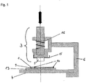
- Fig. 1 Schematic side view of an excising device and a solid support
- an excising device with a solid support (1) containing a biological sample (not shown) placed on a laterally movable sled (13) which is part of a bearing (4), wherein the solid support and the sled or the bearing, respectively, are separated by a separation layer (9) that can be removed after use.
- the solid support and the separation layer are attached to the sled or the bearing, respectively, with the help of a holder (14).
- the bearing is interconnected with the punch (3) comprising a cutting edge (5) by means of a fixture (6).
- the fixture also provides for specific positioning and guiding of the bearing and the punch relatively to each other, so that the movement of the punch toward the bearing is laterally guided.
- the punch comprises a lever (15) as a mechanism for inserting or ejecting the cutting edge, and further a spring (16) applying a reset force upon a vertical movement of the punch toward the solid support.
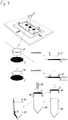
- Fig.2 Perspective view of an excising device and a solid support containing a biological sample according to Fig. 1
- the solid support (1) depicted with a dotted line, is placed on a sled as a laterally movable element (13) as part of a bearing (4) with the help of pins as a holder (14), wherein solid support and sled are separated by a separation layer (9).
- a separation layer (9) contains three round-shaped biological samples (2) to be excised via the cutting edge (5) comprised by the punch (not shown).
- the fixture connecting the punch and the bearing is not depicted for the sake of clarity.
- FIG. 3 Perspective view of a vessel containing a portion of a solid support containing a biological sample
- a vessel (7) is provided as a receptacle for the excised portion of the solid support containing the biological sample (2).
- the rim of the vessel opening (8) serves as a bearing.
- Fig. 4 Depiction of the workflow of an excision and subsequent transfer of the excised portion of the solid support to a vessel
- a portion of solid support (2) is excised with a cutting edge (5), whereby the cutting edge is disabled by deformation as a result of the excision. From its original, functional shape (5) it is converted into a non-functional form (10), i.e. it is not available for further excision procedures. However, it is deformed towards its inside, such that the excised portion of solid support (2) is stabilized within the deformed cutting edge.
- the deformed cutting edge (10) is then turned around and placed on the rim of a receiving vessel (19), so that the excised portion of solid support can be easily pushed into the receiving vessel by using a sterile device (11) which can e.g. be a sterile pipet tip. The empty deformed cutting edge can then by removed from the vessel and discarded, and the vessel may subsequently be closed.
- the order of the steps within the depicted workflow is indicated by dotted arrows.
- Fig. 5 Perspective view of an excising device wherein the punch is a vessel
- the cutting edge (5) is integrated into the rim of the opening of a vessel forming the punch (12).
- the solid support (1) comprising a biological sample (2) is oriented with the sample facing the cutting edge comprised by the vessel.
- the fixture connecting the bearing and the vessel is not depicted for the sake of clarity.
- Fig. 6 Perspective view of a device and mechanism for inserting or ejecting the cutting edge which can be used e.g. in embodiments according to figures 1 to 3
- the cutting edge (5) is placed into a movable socket (17) which can be rotated laterally around an axis (18).
- Fig. 6a the cutting edge (5) is inserted into the socket (17) which is, in this step, laterally displaced in relation to the remaining part of the punch (3).
- Fig. 6c the socket (17) containing the cutting edge (5) is attached to the remainder of the punch (3).
- the cutting edge is now ready to be used in the context of the excising device. After an excision event, it can be replaced by performing the steps depicted in 6c to 6a in the order c b a.
Landscapes
- Physics & Mathematics (AREA)
- Health & Medical Sciences (AREA)
- Life Sciences & Earth Sciences (AREA)
- Chemical & Material Sciences (AREA)
- Analytical Chemistry (AREA)
- Biochemistry (AREA)
- General Health & Medical Sciences (AREA)
- General Physics & Mathematics (AREA)
- Immunology (AREA)
- Pathology (AREA)
- Sampling And Sample Adjustment (AREA)
Claims (4)
- Ein Verfahren zum Herausschneiden eines Teils aus einem festen Träger (1), der eine biologische Probe (2) enthält, wobei das Verfahren die folgenden Schritte umfasst:a) Bereitstellen einer biologischen Probe auf einem festen Träger, wobei der feste Träger aus mindestens einem Material, ausgewählt aus der Gruppe von Cellulose, Glas, Kunststoff oder Baumwolle, hergestellt istb) Bereitstellen einer Vorrichtung zum Herausschneiden zum Herausschneiden eines Teils eines festen Trägers, der eine biologische Probe enthält, wobei die Vorrichtung eine Stanze (3) und eine Auflage (4) umfasst, wobei die Stanze eine Schneidkante (5), die eine Metallöse ist, umfasst, wobei die Vorrichtung ferner eine Halterung (6) umfasst, welche die Stanze und die Auflage verbindet und sie in einer Beziehung zueinander führtc) Herausschneiden eines Teils des festen Trägers, der die biologische Probe enthält, mit der Vorrichtung durch Drücken der Schneidkante gegen den festen Träger, der durch die Auflage gestützt ist, wobei die Schneidkante durch Verformung als Ergebnis des Herausschneidens deaktiviert wirdd) Trennen des herausgeschnittenen Teils des festen Trägers, der die biologische Probe enthält, vom Rest des festen Trägerse) Entfernen der Schneidkante aus der Vorrichtung zum Herausschneiden und Verwerfen der Schneidkantewobei der feste Träger und die Auflage durch eine Trennschicht (9) getrennt sind.
- Das Verfahren nach Anspruch 1, ferner umfassend das Übertragen des Teils in ein Behältnis (7).
- Das Verfahren nach einem der vorhergehenden Ansprüche, wobei die Auflage der Rand (8) einer Behältnisöffnung ist.
- Das Verfahren nach einem der vorhergehenden Ansprüche, wobei die Schneidkante ringförmig ist.
Priority Applications (1)
| Application Number | Priority Date | Filing Date | Title |
|---|---|---|---|
| EP10158316.9A EP2249140B1 (de) | 2009-05-07 | 2010-03-30 | Verfahren zum Herausschneiden von biologischen Proben auf einem festen Träger |
Applications Claiming Priority (2)
| Application Number | Priority Date | Filing Date | Title |
|---|---|---|---|
| EP09100270 | 2009-05-07 | ||
| EP10158316.9A EP2249140B1 (de) | 2009-05-07 | 2010-03-30 | Verfahren zum Herausschneiden von biologischen Proben auf einem festen Träger |
Publications (2)
| Publication Number | Publication Date |
|---|---|
| EP2249140A1 EP2249140A1 (de) | 2010-11-10 |
| EP2249140B1 true EP2249140B1 (de) | 2018-06-27 |
Family
ID=41203634
Family Applications (1)
| Application Number | Title | Priority Date | Filing Date |
|---|---|---|---|
| EP10158316.9A Active EP2249140B1 (de) | 2009-05-07 | 2010-03-30 | Verfahren zum Herausschneiden von biologischen Proben auf einem festen Träger |
Country Status (2)
| Country | Link |
|---|---|
| US (1) | US20110111503A1 (de) |
| EP (1) | EP2249140B1 (de) |
Cited By (2)
| Publication number | Priority date | Publication date | Assignee | Title |
|---|---|---|---|---|
| CN109612875A (zh) * | 2019-02-25 | 2019-04-12 | 赵云红 | 一种土壤中酚类挥发性有机物检测装置及其检测方法 |
| EP3911744A4 (de) * | 2019-01-15 | 2023-03-15 | Westinghouse Electric Company Llc | Minimalinvasiver mikroprobennehmer zur intakten entfernung von oberflächenbelägen und substraten |
Families Citing this family (10)
| Publication number | Priority date | Publication date | Assignee | Title |
|---|---|---|---|---|
| JP6154384B2 (ja) | 2011-09-23 | 2017-06-28 | ウオーターズ・テクノロジーズ・コーポレイシヨン | 乾燥サンプルカード用固相抽出デバイス |
| US8759075B2 (en) | 2012-07-13 | 2014-06-24 | Diomics Corporation | Biologic sample collection devices and methods of production and use thereof |
| US10519434B2 (en) | 2012-07-13 | 2019-12-31 | Diomics Corporation | Biologic sample collection devices and methods of production and use thereof |
| BR112015001460A2 (pt) | 2012-07-24 | 2017-07-04 | Cryoxtract Instr Llc | sonda de escavação, sistemas para colher núcleo de amostras congelados de uma pluralidade de amostras congeladas, para coletar alíquotas congeladas de amostras biológicas congeladas contidas em contêineres de amostras, para armazenar amostras de tecido congeladas, métodos de colher um núcleo de amostra congelada de uma amostra congelada, para aumentar a probabilidade de um operador usar apenas as sondas de escavação, para preparar e amostrar uma amostra de tecido em um contêiner de amostra de tecido, e de armazenamento de uma amostra de tecido, dispositivo portátil de escavação, bandeja, contêiner de amostra de tecido, kit para preparação de u,a a,ostra de tecido, transporte de tecido para suportar a amostra de tecido, e, combinação de transporte de tecido e dispositivo de escavação. |
| US9662096B2 (en) | 2014-05-01 | 2017-05-30 | Diomics Corporation | Devices and kits for collection, storage and analysis of samples and methods of production and use thereof |
| WO2016014455A1 (en) | 2014-07-22 | 2016-01-28 | Diomics Corporation | Airborne agent collectors, methods, systems and devices for monitoring airborne agents |
| WO2016014822A1 (en) * | 2014-07-25 | 2016-01-28 | Ge Healthcare Uk Limited | Screening and monitoring the progression of type 2 diabetes by the molecular identification of gut flora using fta as a faecal collection device |
| EP3179912B1 (de) | 2014-08-15 | 2020-10-14 | Diomics Corporation | Filme zur entnahme und analyse biologischer analyten sowie verfahren zur herstellung |
| US20170234787A1 (en) * | 2016-02-15 | 2017-08-17 | Edaphis Inc. | Porous medium extraction system, porous medium sensor assembly and porous medium infiltrometer |
| CN107446311B (zh) * | 2017-08-21 | 2020-01-03 | 大唐七台河发电有限责任公司 | 一种万能半自动滤油纸打孔装置 |
Citations (2)
| Publication number | Priority date | Publication date | Assignee | Title |
|---|---|---|---|---|
| US20030039788A1 (en) * | 2001-08-17 | 2003-02-27 | Harris Joel Steven | Cutting mat for material sampling |
| CA2380736A1 (en) * | 2002-04-02 | 2003-10-02 | Joel S. Harris | Motor driven sampling apparatus for material collection |
Family Cites Families (16)
| Publication number | Priority date | Publication date | Assignee | Title |
|---|---|---|---|---|
| US2424474A (en) * | 1945-11-15 | 1947-07-22 | Ethel A Macgregor | Punch |
| US2449108A (en) * | 1946-06-22 | 1948-09-14 | George P Carlock | Hand operated leather punching machine |
| US4965188A (en) | 1986-08-22 | 1990-10-23 | Cetus Corporation | Process for amplifying, detecting, and/or cloning nucleic acid sequences using a thermostable enzyme |
| US4683202A (en) | 1985-03-28 | 1987-07-28 | Cetus Corporation | Process for amplifying nucleic acid sequences |
| US4683195A (en) | 1986-01-30 | 1987-07-28 | Cetus Corporation | Process for amplifying, detecting, and/or-cloning nucleic acid sequences |
| US4800159A (en) | 1986-02-07 | 1989-01-24 | Cetus Corporation | Process for amplifying, detecting, and/or cloning nucleic acid sequences |
| US6342143B1 (en) * | 2000-01-06 | 2002-01-29 | Carnegie Mellon University | Cutting tool for multiple sample retrieval from gelatinous material |
| DE10313340B3 (de) * | 2003-03-25 | 2004-08-26 | GSF - Forschungszentrum für Umwelt und Gesundheit GmbH | Gewebestanzvorrichtung |
| US20070079721A1 (en) * | 2003-09-02 | 2007-04-12 | Poly Systems Pty Ltd. | Projectile containing a gel impregnated with an abrasive agent |
| US20050129579A1 (en) * | 2003-11-05 | 2005-06-16 | Bizpac (Australia) Pty Ltd. | System and method for analysing laboratory samples |
| FI20045456A7 (fi) * | 2004-11-24 | 2006-05-25 | Wallac Oy | Lävistystyökalu biologisen näytepalan ottamiseksi |
| US7332268B2 (en) * | 2005-04-07 | 2008-02-19 | Bio-Rad Laboratories, Inc. | Layered support sheet for high-yield spot cutting from gels or membranes |
| CN102943106A (zh) * | 2006-03-13 | 2013-02-27 | 珀金埃尔默健康科学股份有限公司 | 用于质谱法检测的底物和内标 |
| US20080064983A1 (en) * | 2006-09-08 | 2008-03-13 | Jenrik Ag, Llc | Livestock tissue identification method and device |
| USD568401S1 (en) * | 2006-10-18 | 2008-05-06 | Officemate International Corp. | Paper punch |
| US20090004662A1 (en) * | 2007-06-18 | 2009-01-01 | Applera Corporation | Method and compositions for nucleic acid amplification |
-
2010
- 2010-03-30 EP EP10158316.9A patent/EP2249140B1/de active Active
- 2010-05-05 US US12/774,587 patent/US20110111503A1/en not_active Abandoned
Patent Citations (2)
| Publication number | Priority date | Publication date | Assignee | Title |
|---|---|---|---|---|
| US20030039788A1 (en) * | 2001-08-17 | 2003-02-27 | Harris Joel Steven | Cutting mat for material sampling |
| CA2380736A1 (en) * | 2002-04-02 | 2003-10-02 | Joel S. Harris | Motor driven sampling apparatus for material collection |
Cited By (4)
| Publication number | Priority date | Publication date | Assignee | Title |
|---|---|---|---|---|
| EP3911744A4 (de) * | 2019-01-15 | 2023-03-15 | Westinghouse Electric Company Llc | Minimalinvasiver mikroprobennehmer zur intakten entfernung von oberflächenbelägen und substraten |
| US12360016B2 (en) | 2019-01-15 | 2025-07-15 | Westinghouse Electric Company Llc | Minimally invasive microsampler for intact removal of surface deposits and substrates |
| CN109612875A (zh) * | 2019-02-25 | 2019-04-12 | 赵云红 | 一种土壤中酚类挥发性有机物检测装置及其检测方法 |
| CN109612875B (zh) * | 2019-02-25 | 2021-08-24 | 广东万德检测技术股份有限公司 | 一种土壤中酚类挥发性有机物检测装置及其检测方法 |
Also Published As
| Publication number | Publication date |
|---|---|
| US20110111503A1 (en) | 2011-05-12 |
| EP2249140A1 (de) | 2010-11-10 |
Similar Documents
| Publication | Publication Date | Title |
|---|---|---|
| EP2249140B1 (de) | Verfahren zum Herausschneiden von biologischen Proben auf einem festen Träger | |
| US20220176370A1 (en) | Method for purifying and testing biomolecules from biological samples | |
| CN208362349U (zh) | 分子诊断装置 | |
| JP5281085B2 (ja) | 試料処理装置 | |
| US5846489A (en) | System for opening closures of vessels and for the contamination-free operation of reaction sequences | |
| KR102168912B1 (ko) | 통합형 전달 모듈을 구비한 테스트 카트리지 | |
| US6817256B2 (en) | Pipette sampling system | |
| CN103175975B (zh) | 用于防止污染的方法 | |
| US20040219662A1 (en) | Analytical and diagnostic instrument | |
| CN117466230A (zh) | 用于用封闭盖自动封闭样品容器的开口端的方法、可移动盖夹持器及样品容器封闭系统 |
Legal Events
| Date | Code | Title | Description |
|---|---|---|---|
| PUAI | Public reference made under article 153(3) epc to a published international application that has entered the european phase |
Free format text: ORIGINAL CODE: 0009012 |
|
| AK | Designated contracting states |
Kind code of ref document: A1 Designated state(s): AT BE BG CH CY CZ DE DK EE ES FI FR GB GR HR HU IE IS IT LI LT LU LV MC MK MT NL NO PL PT RO SE SI SK SM TR |
|
| AX | Request for extension of the european patent |
Extension state: AL BA ME RS |
|
| 17P | Request for examination filed |
Effective date: 20110510 |
|
| 17Q | First examination report despatched |
Effective date: 20111013 |
|
| STAA | Information on the status of an ep patent application or granted ep patent |
Free format text: STATUS: EXAMINATION IS IN PROGRESS |
|
| GRAP | Despatch of communication of intention to grant a patent |
Free format text: ORIGINAL CODE: EPIDOSNIGR1 |
|
| STAA | Information on the status of an ep patent application or granted ep patent |
Free format text: STATUS: GRANT OF PATENT IS INTENDED |
|
| INTG | Intention to grant announced |
Effective date: 20180313 |
|
| GRAS | Grant fee paid |
Free format text: ORIGINAL CODE: EPIDOSNIGR3 |
|
| GRAA | (expected) grant |
Free format text: ORIGINAL CODE: 0009210 |
|
| STAA | Information on the status of an ep patent application or granted ep patent |
Free format text: STATUS: THE PATENT HAS BEEN GRANTED |
|
| AK | Designated contracting states |
Kind code of ref document: B1 Designated state(s): AT BE BG CH CY CZ DE DK EE ES FI FR GB GR HR HU IE IS IT LI LT LU LV MC MK MT NL NO PL PT RO SE SI SK SM TR |
|
| REG | Reference to a national code |
Ref country code: GB Ref legal event code: FG4D |
|
| RIN1 | Information on inventor provided before grant (corrected) |
Inventor name: PRETSCH, ROBERT-ELMAR Inventor name: SIEDEL, JOACHIM WALTER Inventor name: NUSSBAUM, URS Inventor name: GRUEBL, TOMAS |
|
| REG | Reference to a national code |
Ref country code: AT Ref legal event code: REF Ref document number: 1012744 Country of ref document: AT Kind code of ref document: T Effective date: 20180715 |
|
| REG | Reference to a national code |
Ref country code: IE Ref legal event code: FG4D |
|
| REG | Reference to a national code |
Ref country code: DE Ref legal event code: R096 Ref document number: 602010051474 Country of ref document: DE |
|
| PG25 | Lapsed in a contracting state [announced via postgrant information from national office to epo] |
Ref country code: NO Free format text: LAPSE BECAUSE OF FAILURE TO SUBMIT A TRANSLATION OF THE DESCRIPTION OR TO PAY THE FEE WITHIN THE PRESCRIBED TIME-LIMIT Effective date: 20180927 Ref country code: LT Free format text: LAPSE BECAUSE OF FAILURE TO SUBMIT A TRANSLATION OF THE DESCRIPTION OR TO PAY THE FEE WITHIN THE PRESCRIBED TIME-LIMIT Effective date: 20180627 Ref country code: SE Free format text: LAPSE BECAUSE OF FAILURE TO SUBMIT A TRANSLATION OF THE DESCRIPTION OR TO PAY THE FEE WITHIN THE PRESCRIBED TIME-LIMIT Effective date: 20180627 Ref country code: BG Free format text: LAPSE BECAUSE OF FAILURE TO SUBMIT A TRANSLATION OF THE DESCRIPTION OR TO PAY THE FEE WITHIN THE PRESCRIBED TIME-LIMIT Effective date: 20180927 Ref country code: FI Free format text: LAPSE BECAUSE OF FAILURE TO SUBMIT A TRANSLATION OF THE DESCRIPTION OR TO PAY THE FEE WITHIN THE PRESCRIBED TIME-LIMIT Effective date: 20180627 |
|
| REG | Reference to a national code |
Ref country code: NL Ref legal event code: MP Effective date: 20180627 |
|
| REG | Reference to a national code |
Ref country code: LT Ref legal event code: MG4D |
|
| PG25 | Lapsed in a contracting state [announced via postgrant information from national office to epo] |
Ref country code: GR Free format text: LAPSE BECAUSE OF FAILURE TO SUBMIT A TRANSLATION OF THE DESCRIPTION OR TO PAY THE FEE WITHIN THE PRESCRIBED TIME-LIMIT Effective date: 20180928 Ref country code: HR Free format text: LAPSE BECAUSE OF FAILURE TO SUBMIT A TRANSLATION OF THE DESCRIPTION OR TO PAY THE FEE WITHIN THE PRESCRIBED TIME-LIMIT Effective date: 20180627 Ref country code: LV Free format text: LAPSE BECAUSE OF FAILURE TO SUBMIT A TRANSLATION OF THE DESCRIPTION OR TO PAY THE FEE WITHIN THE PRESCRIBED TIME-LIMIT Effective date: 20180627 |
|
| REG | Reference to a national code |
Ref country code: AT Ref legal event code: MK05 Ref document number: 1012744 Country of ref document: AT Kind code of ref document: T Effective date: 20180627 |
|
| PG25 | Lapsed in a contracting state [announced via postgrant information from national office to epo] |
Ref country code: NL Free format text: LAPSE BECAUSE OF FAILURE TO SUBMIT A TRANSLATION OF THE DESCRIPTION OR TO PAY THE FEE WITHIN THE PRESCRIBED TIME-LIMIT Effective date: 20180627 |
|
| PG25 | Lapsed in a contracting state [announced via postgrant information from national office to epo] |
Ref country code: CZ Free format text: LAPSE BECAUSE OF FAILURE TO SUBMIT A TRANSLATION OF THE DESCRIPTION OR TO PAY THE FEE WITHIN THE PRESCRIBED TIME-LIMIT Effective date: 20180627 Ref country code: RO Free format text: LAPSE BECAUSE OF FAILURE TO SUBMIT A TRANSLATION OF THE DESCRIPTION OR TO PAY THE FEE WITHIN THE PRESCRIBED TIME-LIMIT Effective date: 20180627 Ref country code: IS Free format text: LAPSE BECAUSE OF FAILURE TO SUBMIT A TRANSLATION OF THE DESCRIPTION OR TO PAY THE FEE WITHIN THE PRESCRIBED TIME-LIMIT Effective date: 20181027 Ref country code: AT Free format text: LAPSE BECAUSE OF FAILURE TO SUBMIT A TRANSLATION OF THE DESCRIPTION OR TO PAY THE FEE WITHIN THE PRESCRIBED TIME-LIMIT Effective date: 20180627 Ref country code: PL Free format text: LAPSE BECAUSE OF FAILURE TO SUBMIT A TRANSLATION OF THE DESCRIPTION OR TO PAY THE FEE WITHIN THE PRESCRIBED TIME-LIMIT Effective date: 20180627 Ref country code: EE Free format text: LAPSE BECAUSE OF FAILURE TO SUBMIT A TRANSLATION OF THE DESCRIPTION OR TO PAY THE FEE WITHIN THE PRESCRIBED TIME-LIMIT Effective date: 20180627 Ref country code: SK Free format text: LAPSE BECAUSE OF FAILURE TO SUBMIT A TRANSLATION OF THE DESCRIPTION OR TO PAY THE FEE WITHIN THE PRESCRIBED TIME-LIMIT Effective date: 20180627 |
|
| PG25 | Lapsed in a contracting state [announced via postgrant information from national office to epo] |
Ref country code: IT Free format text: LAPSE BECAUSE OF FAILURE TO SUBMIT A TRANSLATION OF THE DESCRIPTION OR TO PAY THE FEE WITHIN THE PRESCRIBED TIME-LIMIT Effective date: 20180627 Ref country code: SM Free format text: LAPSE BECAUSE OF FAILURE TO SUBMIT A TRANSLATION OF THE DESCRIPTION OR TO PAY THE FEE WITHIN THE PRESCRIBED TIME-LIMIT Effective date: 20180627 Ref country code: ES Free format text: LAPSE BECAUSE OF FAILURE TO SUBMIT A TRANSLATION OF THE DESCRIPTION OR TO PAY THE FEE WITHIN THE PRESCRIBED TIME-LIMIT Effective date: 20180627 |
|
| REG | Reference to a national code |
Ref country code: DE Ref legal event code: R097 Ref document number: 602010051474 Country of ref document: DE |
|
| PLBE | No opposition filed within time limit |
Free format text: ORIGINAL CODE: 0009261 |
|
| STAA | Information on the status of an ep patent application or granted ep patent |
Free format text: STATUS: NO OPPOSITION FILED WITHIN TIME LIMIT |
|
| PG25 | Lapsed in a contracting state [announced via postgrant information from national office to epo] |
Ref country code: DK Free format text: LAPSE BECAUSE OF FAILURE TO SUBMIT A TRANSLATION OF THE DESCRIPTION OR TO PAY THE FEE WITHIN THE PRESCRIBED TIME-LIMIT Effective date: 20180627 |
|
| 26N | No opposition filed |
Effective date: 20190328 |
|
| PG25 | Lapsed in a contracting state [announced via postgrant information from national office to epo] |
Ref country code: SI Free format text: LAPSE BECAUSE OF FAILURE TO SUBMIT A TRANSLATION OF THE DESCRIPTION OR TO PAY THE FEE WITHIN THE PRESCRIBED TIME-LIMIT Effective date: 20180627 |
|
| PG25 | Lapsed in a contracting state [announced via postgrant information from national office to epo] |
Ref country code: MC Free format text: LAPSE BECAUSE OF FAILURE TO SUBMIT A TRANSLATION OF THE DESCRIPTION OR TO PAY THE FEE WITHIN THE PRESCRIBED TIME-LIMIT Effective date: 20180627 |
|
| PG25 | Lapsed in a contracting state [announced via postgrant information from national office to epo] |
Ref country code: LU Free format text: LAPSE BECAUSE OF NON-PAYMENT OF DUE FEES Effective date: 20190330 |
|
| REG | Reference to a national code |
Ref country code: BE Ref legal event code: MM Effective date: 20190331 |
|
| PG25 | Lapsed in a contracting state [announced via postgrant information from national office to epo] |
Ref country code: IE Free format text: LAPSE BECAUSE OF NON-PAYMENT OF DUE FEES Effective date: 20190330 |
|
| PG25 | Lapsed in a contracting state [announced via postgrant information from national office to epo] |
Ref country code: BE Free format text: LAPSE BECAUSE OF NON-PAYMENT OF DUE FEES Effective date: 20190331 |
|
| PG25 | Lapsed in a contracting state [announced via postgrant information from national office to epo] |
Ref country code: TR Free format text: LAPSE BECAUSE OF FAILURE TO SUBMIT A TRANSLATION OF THE DESCRIPTION OR TO PAY THE FEE WITHIN THE PRESCRIBED TIME-LIMIT Effective date: 20180627 |
|
| PG25 | Lapsed in a contracting state [announced via postgrant information from national office to epo] |
Ref country code: PT Free format text: LAPSE BECAUSE OF FAILURE TO SUBMIT A TRANSLATION OF THE DESCRIPTION OR TO PAY THE FEE WITHIN THE PRESCRIBED TIME-LIMIT Effective date: 20181029 Ref country code: MT Free format text: LAPSE BECAUSE OF NON-PAYMENT OF DUE FEES Effective date: 20190330 |
|
| PG25 | Lapsed in a contracting state [announced via postgrant information from national office to epo] |
Ref country code: CY Free format text: LAPSE BECAUSE OF FAILURE TO SUBMIT A TRANSLATION OF THE DESCRIPTION OR TO PAY THE FEE WITHIN THE PRESCRIBED TIME-LIMIT Effective date: 20180627 |
|
| PG25 | Lapsed in a contracting state [announced via postgrant information from national office to epo] |
Ref country code: HU Free format text: LAPSE BECAUSE OF FAILURE TO SUBMIT A TRANSLATION OF THE DESCRIPTION OR TO PAY THE FEE WITHIN THE PRESCRIBED TIME-LIMIT; INVALID AB INITIO Effective date: 20100330 |
|
| PG25 | Lapsed in a contracting state [announced via postgrant information from national office to epo] |
Ref country code: MK Free format text: LAPSE BECAUSE OF FAILURE TO SUBMIT A TRANSLATION OF THE DESCRIPTION OR TO PAY THE FEE WITHIN THE PRESCRIBED TIME-LIMIT Effective date: 20180627 |
|
| PGFP | Annual fee paid to national office [announced via postgrant information from national office to epo] |
Ref country code: DE Payment date: 20250218 Year of fee payment: 16 |
|
| PGFP | Annual fee paid to national office [announced via postgrant information from national office to epo] |
Ref country code: FR Payment date: 20250218 Year of fee payment: 16 |
|
| PGFP | Annual fee paid to national office [announced via postgrant information from national office to epo] |
Ref country code: GB Payment date: 20250221 Year of fee payment: 16 |
|
| PGFP | Annual fee paid to national office [announced via postgrant information from national office to epo] |
Ref country code: CH Payment date: 20250401 Year of fee payment: 16 |