EP2249113A1 - Steam dryer - Google Patents
Steam dryer Download PDFInfo
- Publication number
- EP2249113A1 EP2249113A1 EP09159735A EP09159735A EP2249113A1 EP 2249113 A1 EP2249113 A1 EP 2249113A1 EP 09159735 A EP09159735 A EP 09159735A EP 09159735 A EP09159735 A EP 09159735A EP 2249113 A1 EP2249113 A1 EP 2249113A1
- Authority
- EP
- European Patent Office
- Prior art keywords
- drum
- steam
- discharge end
- pipe elements
- steam pipe
- Prior art date
- Legal status (The legal status is an assumption and is not a legal conclusion. Google has not performed a legal analysis and makes no representation as to the accuracy of the status listed.)
- Granted
Links
Images

Classifications
-
- F—MECHANICAL ENGINEERING; LIGHTING; HEATING; WEAPONS; BLASTING
- F26—DRYING
- F26B—DRYING SOLID MATERIALS OR OBJECTS BY REMOVING LIQUID THEREFROM
- F26B11/00—Machines or apparatus for drying solid materials or objects with movement which is non-progressive
- F26B11/02—Machines or apparatus for drying solid materials or objects with movement which is non-progressive in moving drums or other mainly-closed receptacles
- F26B11/026—Arrangements for charging or discharging the materials to be dried, e.g. discharging by reversing drum rotation, using spiral-type inserts
-
- F—MECHANICAL ENGINEERING; LIGHTING; HEATING; WEAPONS; BLASTING
- F26—DRYING
- F26B—DRYING SOLID MATERIALS OR OBJECTS BY REMOVING LIQUID THEREFROM
- F26B11/00—Machines or apparatus for drying solid materials or objects with movement which is non-progressive
- F26B11/02—Machines or apparatus for drying solid materials or objects with movement which is non-progressive in moving drums or other mainly-closed receptacles
- F26B11/04—Machines or apparatus for drying solid materials or objects with movement which is non-progressive in moving drums or other mainly-closed receptacles rotating about a horizontal or slightly-inclined axis
- F26B11/0404—Machines or apparatus for drying solid materials or objects with movement which is non-progressive in moving drums or other mainly-closed receptacles rotating about a horizontal or slightly-inclined axis with internal subdivision of the drum, e.g. for subdividing or recycling the material to be dried
- F26B11/0409—Machines or apparatus for drying solid materials or objects with movement which is non-progressive in moving drums or other mainly-closed receptacles rotating about a horizontal or slightly-inclined axis with internal subdivision of the drum, e.g. for subdividing or recycling the material to be dried the subdivision consisting of a plurality of substantially radially oriented internal walls, e.g. forming multiple sector-shaped chambers
-
- F—MECHANICAL ENGINEERING; LIGHTING; HEATING; WEAPONS; BLASTING
- F26—DRYING
- F26B—DRYING SOLID MATERIALS OR OBJECTS BY REMOVING LIQUID THEREFROM
- F26B11/00—Machines or apparatus for drying solid materials or objects with movement which is non-progressive
- F26B11/02—Machines or apparatus for drying solid materials or objects with movement which is non-progressive in moving drums or other mainly-closed receptacles
- F26B11/04—Machines or apparatus for drying solid materials or objects with movement which is non-progressive in moving drums or other mainly-closed receptacles rotating about a horizontal or slightly-inclined axis
- F26B11/0445—Machines or apparatus for drying solid materials or objects with movement which is non-progressive in moving drums or other mainly-closed receptacles rotating about a horizontal or slightly-inclined axis having conductive heating arrangements, e.g. heated drum wall
- F26B11/045—Machines or apparatus for drying solid materials or objects with movement which is non-progressive in moving drums or other mainly-closed receptacles rotating about a horizontal or slightly-inclined axis having conductive heating arrangements, e.g. heated drum wall using heated internal elements, e.g. which move through or convey the materials to be dried
Definitions
- the invention concerns a steam dryer for evaporating of water and/or other liquid from wet materials or evaporating of materials in a liquid state, comprising:
- the drying drum is filled to the desired quantity, the supply of steam is started into the set of pipes placed in the interior of the drying drum, and at the same time the drying drum starts revolving. After the material to be dried has been made sufficiently dry, the rotation of the drum is stopped, the supply of steam is switched off, and the drum is emptied.
- a batch-type dryer that, exactly owing to its mode of operation, the dryer cannot be used smoothly for drying of large quantities of material.
- the arrangement is, as a rule, such that the drying drum is rotated constantly, and material to be dried is supplied into the interior of the drum through one end of the drum.
- steam is passed constantly into the pipe system provided in the interior of the drum.
- the drum is provided with purposeful means by which it is rotated during drying, and further, the wet material that is fed into the drum during drying is carried towards the opposite end of the drum, out of which end the material is discharged.
- the drum is provided with an adjustable overflow edge or with adjustable discharge openings, and further, it is common that the position of inclination of the drum can be adjusted within certain limits so as to regulate the dwell of the concentrate material in the drum.
- the steam dryer described in WO 98/02700 can be mentioned.
- a further prior-art dryer arrangement is such that in it a separate rotor is employed, which forms the heating face and around which rotor there is a stationary fixed basin placed in a horizontal plane.
- the rotor consists of a number of parallel groups of pipes, which have been arranged along a central tube. Each group of pipes usually comprises a number of concentric pipe rings, and the heat transfer medium that is used can be steam or a liquid.
- the system of steam pipes which has been mounted from its ends by means of bearings and which revolves in the wet materials to be dried, imposes a restriction of size, and the size of the equipment cannot be increased economically when the amount of wet materials is increased.
- the object of the present invention is to provide a steam dryer for evaporating of water and/or other liquid from wet materials or evaporating of materials in a liquid state, in which dryer the steam distributor manifold, radial connection pipes and flexible hoses are not exposed to the difficult environment of flying dusty, moist and corrosive vapour so that abrasive wear is minimized or at least it does not cause problems and that the need for maintenance has remarkably been reduced and if needed the maintenance easy to do due to the easy access to said components.
- Another object of the present invention is to provide a steam dryer in which the contact area between the steam pipe elements and wet material is increased in order to obtain higher drying efficiency of the dryer.
- the first embodiment of the present invention is mainly characterized in that the stationary end chamber is arranged at the discharge end area of the drum in the axial direction between the discharge end plate and the feed end plate such that the discharge end plate is situated outside of the discharge end chamber, said discharge end chamber surrounding a portion of the drum and having a lower opening to discharge dried material or remaining liquid therethrough from the drum and from the discharge end chamber and an upper opening to discharge vapour therethrough from the drum and from the discharge end chamber, and that the steam distributor manifold is arranged at the discharge end of the drum outside of the discharge end plate to supply the steam pipe elements with steam intended for evaporating of water and/or other liquid from wet materials or evaporating of materials in a liquid state as said materials pass through the drum and for removing condensate formed in the steam pipe elements.
- the present invention is mainly characterized in that an inner tube having an inner face and an outer face is fitted inside the drum coaxially therewith so that an annular space is formed between the outer face of the inner tube and the inner face of the shell of the drum, that a plurality of partition walls is arranged in the drum extending radially from the outer face of the inner tube to the inner face of the shell of the drum and longitudinally across a substantial length of the drum such that the partition walls together with the inner face of the shell of the drum and the outer face of the inner tube define compartments therebetween, and that the steam distributor manifold is arranged to supply the steam pipe elements with steam for evaporating of water and/or other liquid from wet materials or evaporating of materials in a liquid state as the materials pass through the drum and for removing condensate formed in the steam pipe elements.
- the drum of the steam dryer is extended in the longitudinal direction so that the end plate of the drum is moved from the inside of the discharge end chamber to the outside of it.
- the flexible hoses, the radial connector pipes and the steam distributor manifold which are attached on the discharge end plate on the outside of the drum are not exposed to the environment of flying dusty, moist and corrosive vapour. Due to this arrangement the need for maintenance is remarkably reduced and the access to these components for inspection and maintenance of the same is easy.
- the drum of the steam dryer is divided into a plurality of separate compartments around the axis of rotation of the drum in order to increase the contact area between the steam pipe elements and the wet material in the drum.
- the wet material from which water or other liquids are to be evaporated is fed into each of said compartments in which it is turned and from which it is conveyed to the discharge end of the drum when the drum is rotating.
- the volumetric efficiency of the drum is thereby better than in the prior art dryers.
- the drum of the dryer and the set of pipes placed inside the drum are rotated during drying, and therefore the drum is provided with a mechanism of rotation suitable for this purpose.
- a mechanism of rotation suitable for this purpose As an example of this a mechanisms described in publication WO 98/02700 or in patent US 6,415,527 can be mentioned. Also, other types of mechanisms of rotation can be used.
- the steam pipe elements placed in the drum can be removed from the drum and replaced separately.
- the service life and the usability of the dryer are improved, because the tube elements can be replaced quickly and easily, which reduces the standstill time of the dryer.
- high drying efficiency is obtained, because the filling degree of the drum can be made high.
- the drum of the steam dryer in accordance with the invention can also be in an inclined position so as to enhance the transfer of the material to be dried and to remove the condensate.
- the steam dryer 10 comprises a cylindrical rotatable drum 11 having a shell 12 with an inner face 12a and an outer face 12b. Steam pipe elements 26 have been fitted in the interior of the drum 11 to rotate along with the drum 11.
- the drum 11 is provided with a feed end 14 structured and arranged to receive wet material or material in a liquid state into said drum 11 said feed end 14 being closed by a feed end plate 15.
- the drum 11 is further provided with a discharge end 16 structured and arranged to discharge vapour and dried material or concentrated liquid from said drum 11 said discharge end 16 being closed by a discharge end plate 17.
- a stationary end chamber 18 is structured and arranged at the discharge end 16 area of said drum 11 in the axial direction between said discharge end plate 17 and said feed end plate 15 so that the discharge end plate 17 is outside of said discharge end chamber 18.
- said stationary discharge end chamber 18 surrounds a portion of the drum 11 and it is provided with a lower opening 19 for discharging dried material or remaining liquid through said lower opening 19 from said drum 11 and said discharge end chamber 18.
- the end chamber 18 is further provided with an upper opening 20 to discharge vapour therethrough from said drum 11 and said discharge end chamber 18.
- a steam distributor manifold 21 is structured and arranged at the discharge end 16 of said drum 11 outside of said discharge end plate 17 coaxially with said drum 11.
- the steam distributor manifold 21 is structured and arranged to supply the steam pipe elements 26 with steam intended for evaporating of water and/or other liquid from wet materials or evaporating of materials in a liquid state as said materials pass through the drum 11 and for removing a condensate formed in said steam pipe elements 26. So steam is fed into the steam pipe elements 26 placed in the interior of the drum 11, and similarly the steam is passed out of the drum 11, through the stationary discharge end chamber 18 arranged at the discharge end 16 of the drum 11.
- the wet materials from which water and/or other liquids are to be evaporated or the materials in a liquid state to be evaporated are passed into the interior of the drum 11 through the feed end 14 of the drum 11.
- the material passes in the axial direction through the drum 11 and is discharged through the stationary discharge end chamber 18 arranged at the discharge end 16 of the drum 11.
- the wet material from which water and/or other liquids are to be evaporated or the material in a liquid state to be evaporated is introduced into the drum 11 by conveyance means 22, e.g. a belt conveyor.
- conveyance means 22 e.g. a belt conveyor.
- a conveyor of a different type can also be used and it is recommended to choose the conveyor type according to the materials to be introduced into the drum 11.
- an opening 23 has been formed into the feed end plate 15 at the feed end 14 of the drum 11, through which opening 23 the conveyance means 22 supply the material into the interior of the drum 11.
- the steam enters into the steam distributor manifold 21 through a rotary joint (not shown) and further therethrough to the steam pipe elements 26 placed in the interior of the drum 11.
- the steam distributor manifold 21 has been fitted in the axial direction outside of the discharge end plate 17 and so axially outside of the discharge end 16 of the drum 11.
- the steam distributor manifold 21 is arranged to rotate with the drum 11.
- the steam distributor manifold 21 is provided with a plurality of radial connector pipes 24, whose inner ends open into the interior of the steam distributor manifold 21 and whose outer ends are closed.
- the radial connector pipes 24 communicate with the steam pipe elements 26 in the interior of the drum 11 through flexible hoses 25 or othet suitable means.
- the steam pipe elements 26 are structured and arranged to be inserted within the drum 11 and being rotatable with said drum 11.
- Each steam pipe element 26 comprises two axial pipes 27 parallel to a longitudinal direction of the drum 11 and a plurality of longitudinally spaced transverse intermediate pipes 28 which interconnect said axial pipes 27.
- the steam pipe elements 26 or actually the axial pipes 27 of said steam pipe elements 26 can extend across the entire axial length of the drum.
- the steam pipe elements 26 may alternatively have been formed so that only a part of them extends across the entire axial length of the drum 11 while the rest of the steam pipe elements 26 extend only partially across the axial length of said drum 11 from the steam supply end, i.e. from the discharge end 16 of the drum.
- As a third alternative of the steam pipe elements 26 all of them may have been formed to extend only partially across the axial length of the drum 11.
- each steam pipe element 26 comprises two axial pipes 27 arranged substantially equidistant from a longitudinal centre line L of the drum 11. Said axial pipes 27 are interconnected by a plurality of longitudinally spaced transverse intermediate pipes 28 as explained above. These steam pipe elements 26 can be separately mounted into and separately removed from the interior of the drum 11. In this embodiment, as shown in Fig.
- the steam pipe elements 26 are fitted one inside the other in a radial direction of the drum at a distance from one another so that the transverse intermediate pipes 28 of an adjacent set of steam pipe elements 26 which are also placed substantially at the same distance from the longitudinal centre line L of the drum 11, form a ring-like formation parallel to the circumference of the drum 11. This naturally depends partly on the form of the intermediate pipes 28.
- said steam pipe elements 26 are arranged within the interior of the drum 11 such that the axial pipes 27 of each steam pipe element 26 are placed at a different distance from the longitudinal centre line L of the drum 11.
- a plurality of support constructions 29 have been arranged, to which support constructions 29 the steam pipe element 26 have been attached by fastening means, which permit movement arising from thermal expansion of the steam pipe elements 26.
- the steam dryer 10 comprises a cylindrical rotatable drum 11 having a shell 12 with an inner face 12a and an outer face 12b as explained above. Inside said drum 11 an inner tube 30 is fitted said inner tube 30 having an inner face 30a and an outer face 30b. The inner tube 30 is fitted inside said drum 11 coaxially therewith so that an annular space is formed between the outer face 30b of said inner tube 30 and the inner face 12a of the shell 12 of the drum 11.
- a plurality of partition walls 31 are arranged in the drum 11 such that said partition walls 31 extend radially from the outer face 30b of the inner tube 30 to the inner face 12a of the shell 12 and longitudinally across a substantial length of the drum 11 so that the partition walls 31 together with the inner face 12a of the shell 12 and the outer face 30b of the inner tube 30 define compartments therebetween.
- the steam pipe elements 26 are inserted within said compartments whereby they are rotatable with the drum 11.
- the drum 11 is formed without any inner tube or partition walls so that the inner face 12a of the shell 12 of the drum 11 defines an open space delimited by the feed end plate 15 and the discharge end plate 17 of the drum 11.
- the steam pipe elements 26 are arranged to be inserted within said space.
- the steam pipe elements 26 can be separately mounted into and separately removed from the interior of the drum 11.
- a dam plate 32 is structured and arranged in the drum 11 at the discharge end 16 area of the drum 11. Said dam plate 32 is mounted at a distance from said discharge end plate 17.
- the dam plate 32 has at least one opening 33 formed therein through which opening 33 dried material, remaining liquid and vapour are discharged from the drum 11 into the stationary end chamber 18.
- the discharge end plate 17 and the dam plate 32 have holes 17a, 32a formed therein through which holes the axial pipes 27 of the steam pipe elements 26 are led.
- Fig. 1 further shows that the transverse intermediate pipes 28 of the steam pipe elements 26 are arranged in the drum 11 in the area between the dam plate 32 and the feed end plate 15 but not in the area between dam plate 32 and the discharge end plate 17.
- openings 34 are formed in the area between the dam plate 32 and the discharge end plate 17. Dried material and/or remaining liquid are discharged through these shell openings 34 from the drum 11 to the discharge end chamber 18.
- each of the steam pipe elements 26 forms a closed space for the steam.
- This has been arranged so that one end of the axial pipes 27 has been closed.
- the axial pipes 27 extend through the dam plate 32 and the discharge end plate 17 of the drum 11 at the discharge end area of the dryer 10, where they communicate with the radial connector pipes 24 through flexible hoses 25, for example steel hoses. At the other end, i.e. at the feed end area of the dryer the axial pipes 27 are closed.
- Vapour and dried material or remaining liquid is/are discharged from the steam dryer 10 through the discharge end 16 of the drum 11.
- openings 34 are formed in the shell 12 of the drum 11 in the area between the dam plate 32 and the discharge end plate 17. Dried material and remaining liquid are discharged through these shell openings 34 from the drum 11 to the discharge end chamber 18.
- the wet material from which water or other liquids are to be evaporated or materials in a liquid state to be evaporated pass through the drum 11, and the dried material and/or remaining liquid is/are discharged through openings 34 formed in the shell 12 of the drum 11 into the discharge end chamber 18 and therefrom for further use and/ or further prosecution.
- the mechanism of rotation of the drum 11 and the mechanism of inclination of the drum 11 are not shown in the figures in the drawing, but, as was already stated above, as the mechanism of rotation and as the mechanism of inclination, it is possible to use, for example, the same type of arrangement described in International publication WO 98/02700 or in US Patent No. 6,415,527 . In such a case, by means of the angle of inclination of the drum 11 and the adjustable speed of rotation, the time the wet materials from which water or other liquids are to be evaporated or materials in a liquid state to be evaporated, stay in the steam dryer 10 can be regulated.
Landscapes
- Engineering & Computer Science (AREA)
- Mechanical Engineering (AREA)
- General Engineering & Computer Science (AREA)
- Life Sciences & Earth Sciences (AREA)
- Sustainable Development (AREA)
- Drying Of Solid Materials (AREA)
- Vaporization, Distillation, Condensation, Sublimation, And Cold Traps (AREA)
- Detail Structures Of Washing Machines And Dryers (AREA)
Abstract
Description
- The invention concerns a steam dryer for evaporating of water and/or other liquid from wet materials or evaporating of materials in a liquid state, comprising:
- a cylindrical rotatable drum having a shell with an inner face and an outer face and provided with a feed end structured and arranged to receive wet material or material in a liquid state into the drum the feed end being delimited by a feed end plate, and a discharge end structured and arranged to discharge vapour and dried material or remaining liquid from the drum the discharge end being equipped with a discharge end plate,
- a plurality of steam pipe elements each of which comprises two axial pipes parallel to a longitudinal direction of the drum and interconnected by a plurality of longitudinally spaced transverse intermediate pipes, the steam pipe elements being structured and arranged to be inserted within the drum and being rotatable therewith,
- a steam distributor manifold structured and arranged at the discharge end of the drum coaxially with said drum, and
- conveyance means disposed at the feed end of the drum and structured and arranged for supplying the wet materials or the materials in a liquid state into the steam dryer for evaporating.
- In the prior art, a number of different types of dryer drums based on the use of steam are known, which drums are used, among other things, for drying of different wet materials. In steam dryers of said type, the material to be dried is introduced into the drying drum, and the steam intended for drying is made to flow in pipes fitted inside the drum. Thus, the material to be dried cannot reach direct contact with the steam. Drying drums can be divided into two main types, i.e. into batch-type dryers and, on the other hand, into continuous dryers. In batch-type dryers, of which, as one example, the dryer described in the German Patent No.
27 24 639 can be mentioned, the drying drum is filled to the desired quantity, the supply of steam is started into the set of pipes placed in the interior of the drying drum, and at the same time the drying drum starts revolving. After the material to be dried has been made sufficiently dry, the rotation of the drum is stopped, the supply of steam is switched off, and the drum is emptied. Thus, it can be considered to be a drawback of a batch-type dryer that, exactly owing to its mode of operation, the dryer cannot be used smoothly for drying of large quantities of material. - In continuous dryers, the arrangement is, as a rule, such that the drying drum is rotated constantly, and material to be dried is supplied into the interior of the drum through one end of the drum. During drying, steam is passed constantly into the pipe system provided in the interior of the drum. The drum is provided with purposeful means by which it is rotated during drying, and further, the wet material that is fed into the drum during drying is carried towards the opposite end of the drum, out of which end the material is discharged. As a rule, the drum is provided with an adjustable overflow edge or with adjustable discharge openings, and further, it is common that the position of inclination of the drum can be adjusted within certain limits so as to regulate the dwell of the concentrate material in the drum. As an example of such continuous drying drums, the steam dryer described in
WO 98/02700 - As regards the construction of the above-described prior-art steam drum dryers, it can be stated by way of example that quite commonly such dryers are used in which the steam pipes have been fitted as substantially parallel to the axis of the drum. In such an arrangement, in some cases, it has been noticed to be a problem that an insulating material layer is formed on the faces of the steam pipes out of the material to be dried. In such prior-art dryers in which longitudinal pipes are used, the filling degree of the devices is relatively low, i.e. of an order of 10 ... 15% of the inside volume of the drum, and such drums are not used commonly in drying of some mineral materials because of their large size and low efficiency.
- A further prior-art dryer arrangement is such that in it a separate rotor is employed, which forms the heating face and around which rotor there is a stationary fixed basin placed in a horizontal plane. As a rule, the rotor consists of a number of parallel groups of pipes, which have been arranged along a central tube. Each group of pipes usually comprises a number of concentric pipe rings, and the heat transfer medium that is used can be steam or a liquid. In this prior-art solution, the system of steam pipes, which has been mounted from its ends by means of bearings and which revolves in the wet materials to be dried, imposes a restriction of size, and the size of the equipment cannot be increased economically when the amount of wet materials is increased. A considerable drawback of dryers of this type is rapid wear of the steam pipes, which causes great problems in drying of abrading minerals, because the rotor revolves in a stationary material bed, in which case the pressure applied by the concentrate to the steam pipes is high and causes intensive wear, as was mentioned above.
- Still further prior art dryer construction is described in
US Patent No. 6,415,527 . In this patent is disclosed a steam dryer in particular intended for drying of concentrates, in which dryer abrasion has been reduced compared to previously described prior art so that abrasion does not cause similar problems. In the dryer drum ofUS 6,415,527 the set of pipes placed in the drum has been formed and composed of elements, which can be removed from the drum and replaced separately. So the service life and the usability of the dryer is quite good, because, if necessary, the tube elements can be replaced quickly and easily, which reduces the standstill time of the dryer. The set of steam pipes in this prior art dryer revolves along with the drum, in which case only a low pressure and a little abrading difference in speed is formed between the material to be dried and the steam pipes, in which case abrasion of the steam pipes cause less problems than in previous dryers. However, some problems still remain and therefore there is still a need for improvements in this type of dryers. - Even though the drying efficiency and the filling degree of the drum of
US 6,415,527 were considered quite acceptable at the time when the construction of said US patent was developed nowadays a demand for still better efficiency has risen. The drum of the steam dryer ofUS 6,415,527 has one uniform cylindrical chamber. Now, in this type drums when wet material to be dried is fed into the drum it is settled at the lower part of the drum so that only a small part of the steam pipes is in contact with said wet material. Therefore the heating area of the steam pipes is not used as efficiently as it should be. Another problem relating to the drum ofUS 6,415,527 lies in the construction of the combination of the steam distribution manifold and the discharge end chamber. In the drum ofUS 6,415,527 said steam distribution manifold with radial connection pipes, flexible hoses etc. are all located in said discharge end chamber. There they are exposed to an environment of flying dusty, moist and corrosive vapour. - The object of the present invention is to provide a steam dryer for evaporating of water and/or other liquid from wet materials or evaporating of materials in a liquid state, in which dryer the steam distributor manifold, radial connection pipes and flexible hoses are not exposed to the difficult environment of flying dusty, moist and corrosive vapour so that abrasive wear is minimized or at least it does not cause problems and that the need for maintenance has remarkably been reduced and if needed the maintenance easy to do due to the easy access to said components.
- Further, another object of the present invention is to provide a steam dryer in which the contact area between the steam pipe elements and wet material is increased in order to obtain higher drying efficiency of the dryer.
- In view of achieving the objectives of the invention, the first embodiment of the present invention is mainly characterized in that the stationary end chamber is arranged at the discharge end area of the drum in the axial direction between the discharge end plate and the feed end plate such that the discharge end plate is situated outside of the discharge end chamber, said discharge end chamber surrounding a portion of the drum and having a lower opening to discharge dried material or remaining liquid therethrough from the drum and from the discharge end chamber and an upper opening to discharge vapour therethrough from the drum and from the discharge end chamber, and that the steam distributor manifold is arranged at the discharge end of the drum outside of the discharge end plate to supply the steam pipe elements with steam intended for evaporating of water and/or other liquid from wet materials or evaporating of materials in a liquid state as said materials pass through the drum and for removing condensate formed in the steam pipe elements.
- According to the second embodiment the present invention is mainly characterized in that an inner tube having an inner face and an outer face is fitted inside the drum coaxially therewith so that an annular space is formed between the outer face of the inner tube and the inner face of the shell of the drum, that a plurality of partition walls is arranged in the drum extending radially from the outer face of the inner tube to the inner face of the shell of the drum and longitudinally across a substantial length of the drum such that the partition walls together with the inner face of the shell of the drum and the outer face of the inner tube define compartments therebetween, and that the steam distributor manifold is arranged to supply the steam pipe elements with steam for evaporating of water and/or other liquid from wet materials or evaporating of materials in a liquid state as the materials pass through the drum and for removing condensate formed in the steam pipe elements.
- In the present invention, according to the first embodiment of the invention, the drum of the steam dryer is extended in the longitudinal direction so that the end plate of the drum is moved from the inside of the discharge end chamber to the outside of it. As a result of this the flexible hoses, the radial connector pipes and the steam distributor manifold which are attached on the discharge end plate on the outside of the drum, are not exposed to the environment of flying dusty, moist and corrosive vapour. Due to this arrangement the need for maintenance is remarkably reduced and the access to these components for inspection and maintenance of the same is easy.
- Further, according to the second embodiment of the invention the drum of the steam dryer is divided into a plurality of separate compartments around the axis of rotation of the drum in order to increase the contact area between the steam pipe elements and the wet material in the drum. The wet material from which water or other liquids are to be evaporated is fed into each of said compartments in which it is turned and from which it is conveyed to the discharge end of the drum when the drum is rotating. The volumetric efficiency of the drum is thereby better than in the prior art dryers.
- The drum of the dryer and the set of pipes placed inside the drum are rotated during drying, and therefore the drum is provided with a mechanism of rotation suitable for this purpose. As an example of this a mechanisms described in publication
WO 98/02700 US 6,415,527 can be mentioned. Also, other types of mechanisms of rotation can be used. - The steam pipe elements placed in the drum can be removed from the drum and replaced separately. The service life and the usability of the dryer are improved, because the tube elements can be replaced quickly and easily, which reduces the standstill time of the dryer. By means of the steam dryer in accordance with the invention, high drying efficiency is obtained, because the filling degree of the drum can be made high.
- The drum of the steam dryer in accordance with the invention can also be in an inclined position so as to enhance the transfer of the material to be dried and to remove the condensate.
- The further advantages, characteristic features and embodiments of the invention will come out in more detail in the following detailed description of the invention, in which the invention is described with reference to the figures in the accompanying drawing.
-
FIG. 1 is a schematic longitudinal sectional view of a steam dryer in accordance with the invention. -
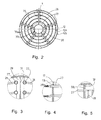
FIG. 2 is a schematic cross-sectional view of a steam dryer in accordance with the invention taken along line A - A ofFIG. 1 . -
FIG. 3 is detail B taken fromFIG. 2 . -
FIG. 4 is detail C taken fromFIG. 1 . -
FIG. 5 is detail D taken fromFIG. 1 . - In
FIG. 1 the steam dryer is denoted generally with thereference numeral 10. Thesteam dryer 10 comprises a cylindricalrotatable drum 11 having ashell 12 with an inner face 12a and anouter face 12b.Steam pipe elements 26 have been fitted in the interior of thedrum 11 to rotate along with thedrum 11. Thedrum 11 is provided with afeed end 14 structured and arranged to receive wet material or material in a liquid state into saiddrum 11 saidfeed end 14 being closed by afeed end plate 15. Thedrum 11 is further provided with adischarge end 16 structured and arranged to discharge vapour and dried material or concentrated liquid from saiddrum 11 saiddischarge end 16 being closed by adischarge end plate 17. - A
stationary end chamber 18 is structured and arranged at the discharge end 16 area of saiddrum 11 in the axial direction between saiddischarge end plate 17 and saidfeed end plate 15 so that thedischarge end plate 17 is outside of saiddischarge end chamber 18. As can be seen inFig. 1 , said stationarydischarge end chamber 18 surrounds a portion of thedrum 11 and it is provided with alower opening 19 for discharging dried material or remaining liquid through saidlower opening 19 from saiddrum 11 and saiddischarge end chamber 18. Theend chamber 18 is further provided with anupper opening 20 to discharge vapour therethrough from saiddrum 11 and saiddischarge end chamber 18. - A
steam distributor manifold 21 is structured and arranged at the discharge end 16 of saiddrum 11 outside of saiddischarge end plate 17 coaxially with saiddrum 11. Thesteam distributor manifold 21 is structured and arranged to supply thesteam pipe elements 26 with steam intended for evaporating of water and/or other liquid from wet materials or evaporating of materials in a liquid state as said materials pass through thedrum 11 and for removing a condensate formed in saidsteam pipe elements 26. So steam is fed into thesteam pipe elements 26 placed in the interior of thedrum 11, and similarly the steam is passed out of thedrum 11, through the stationarydischarge end chamber 18 arranged at the discharge end 16 of thedrum 11. - On the other hand, the wet materials from which water and/or other liquids are to be evaporated or the materials in a liquid state to be evaporated, are passed into the interior of the
drum 11 through thefeed end 14 of thedrum 11. During evaporating, the material passes in the axial direction through thedrum 11 and is discharged through the stationarydischarge end chamber 18 arranged at the discharge end 16 of thedrum 11. The wet material from which water and/or other liquids are to be evaporated or the material in a liquid state to be evaporated is introduced into thedrum 11 by conveyance means 22, e.g. a belt conveyor. A conveyor of a different type can also be used and it is recommended to choose the conveyor type according to the materials to be introduced into thedrum 11. For the supply of the material into thedrum 11, anopening 23 has been formed into thefeed end plate 15 at thefeed end 14 of thedrum 11, through whichopening 23 the conveyance means 22 supply the material into the interior of thedrum 11. The steam enters into thesteam distributor manifold 21 through a rotary joint (not shown) and further therethrough to thesteam pipe elements 26 placed in the interior of thedrum 11. - As already explained above the
steam distributor manifold 21 has been fitted in the axial direction outside of thedischarge end plate 17 and so axially outside of the discharge end 16 of thedrum 11. Thesteam distributor manifold 21 is arranged to rotate with thedrum 11. Thesteam distributor manifold 21 is provided with a plurality ofradial connector pipes 24, whose inner ends open into the interior of thesteam distributor manifold 21 and whose outer ends are closed. Theradial connector pipes 24 communicate with thesteam pipe elements 26 in the interior of thedrum 11 throughflexible hoses 25 or othet suitable means. - The
steam pipe elements 26 are structured and arranged to be inserted within thedrum 11 and being rotatable with saiddrum 11. Eachsteam pipe element 26 comprises twoaxial pipes 27 parallel to a longitudinal direction of thedrum 11 and a plurality of longitudinally spaced transverseintermediate pipes 28 which interconnect saidaxial pipes 27. As is shown inFig. 1 , thesteam pipe elements 26 or actually theaxial pipes 27 of saidsteam pipe elements 26 can extend across the entire axial length of the drum. However, thesteam pipe elements 26 may alternatively have been formed so that only a part of them extends across the entire axial length of thedrum 11 while the rest of thesteam pipe elements 26 extend only partially across the axial length of saiddrum 11 from the steam supply end, i.e. from the discharge end 16 of the drum. As a third alternative of thesteam pipe elements 26 all of them may have been formed to extend only partially across the axial length of thedrum 11. - A preferred embodiment of the structure and arrangement of the
steam pipe elements 26 can be seen especially inFigs. 1 ,2 and 3 . In this embodiment eachsteam pipe element 26 comprises twoaxial pipes 27 arranged substantially equidistant from a longitudinal centre line L of thedrum 11. Saidaxial pipes 27 are interconnected by a plurality of longitudinally spaced transverseintermediate pipes 28 as explained above. Thesesteam pipe elements 26 can be separately mounted into and separately removed from the interior of thedrum 11. In this embodiment, as shown inFig. 2 , thesteam pipe elements 26 are fitted one inside the other in a radial direction of the drum at a distance from one another so that the transverseintermediate pipes 28 of an adjacent set ofsteam pipe elements 26 which are also placed substantially at the same distance from the longitudinal centre line L of thedrum 11, form a ring-like formation parallel to the circumference of thedrum 11. This naturally depends partly on the form of theintermediate pipes 28. According to another (not shown in the drawings) embodiment of the arrangement of thesteam pipe elements 26 saidsteam pipe elements 26 are arranged within the interior of thedrum 11 such that theaxial pipes 27 of eachsteam pipe element 26 are placed at a different distance from the longitudinal centre line L of thedrum 11. In the interior of thedrum 11, a plurality ofsupport constructions 29 have been arranged, to whichsupport constructions 29 thesteam pipe element 26 have been attached by fastening means, which permit movement arising from thermal expansion of thesteam pipe elements 26. - In the embodiment shown in the attached drawing the
steam dryer 10 according to the invention comprises a cylindricalrotatable drum 11 having ashell 12 with an inner face 12a and anouter face 12b as explained above. Inside saiddrum 11 aninner tube 30 is fitted saidinner tube 30 having aninner face 30a and anouter face 30b. Theinner tube 30 is fitted inside saiddrum 11 coaxially therewith so that an annular space is formed between theouter face 30b of saidinner tube 30 and the inner face 12a of theshell 12 of thedrum 11. A plurality ofpartition walls 31 are arranged in thedrum 11 such that saidpartition walls 31 extend radially from theouter face 30b of theinner tube 30 to the inner face 12a of theshell 12 and longitudinally across a substantial length of thedrum 11 so that thepartition walls 31 together with the inner face 12a of theshell 12 and theouter face 30b of theinner tube 30 define compartments therebetween. In this embodiment thesteam pipe elements 26 are inserted within said compartments whereby they are rotatable with thedrum 11. - According to another embodiment (not shown in the drawing) of the
steam dryer 10 thedrum 11 is formed without any inner tube or partition walls so that the inner face 12a of theshell 12 of thedrum 11 defines an open space delimited by thefeed end plate 15 and thedischarge end plate 17 of thedrum 11. Thesteam pipe elements 26 are arranged to be inserted within said space. As in the previous embodiment thesteam pipe elements 26 can be separately mounted into and separately removed from the interior of thedrum 11. - As can best be seen in
Fig. 1 adam plate 32 is structured and arranged in thedrum 11 at the discharge end 16 area of thedrum 11. Saiddam plate 32 is mounted at a distance from saiddischarge end plate 17. Thedam plate 32 has at least oneopening 33 formed therein through whichopening 33 dried material, remaining liquid and vapour are discharged from thedrum 11 into thestationary end chamber 18. Thedischarge end plate 17 and thedam plate 32 haveholes axial pipes 27 of thesteam pipe elements 26 are led.Fig. 1 further shows that the transverseintermediate pipes 28 of thesteam pipe elements 26 are arranged in thedrum 11 in the area between thedam plate 32 and thefeed end plate 15 but not in the area betweendam plate 32 and thedischarge end plate 17. In theshell 12 of thedrum 11openings 34 are formed in the area between thedam plate 32 and thedischarge end plate 17. Dried material and/or remaining liquid are discharged through theseshell openings 34 from thedrum 11 to thedischarge end chamber 18. - In the arrangement in accordance with the present invention, through-flow of steam in the
steam pipe elements 26 has not been employed, but each of thesteam pipe elements 26 forms a closed space for the steam. This has been arranged so that one end of theaxial pipes 27 has been closed. As was already described above, theaxial pipes 27 extend through thedam plate 32 and thedischarge end plate 17 of thedrum 11 at the discharge end area of thedryer 10, where they communicate with theradial connector pipes 24 throughflexible hoses 25, for example steel hoses. At the other end, i.e. at the feed end area of the dryer theaxial pipes 27 are closed. In such a case, when steam is fed into thesteam distributor manifold 21, the steam is carried from saidmanifold 21 through theradial connector pipes 24 and through theflexible hoses 25 into theaxial pipes 27 and into the transverseintermediate pipes 28 which interconnect saidaxial pipes 27. When the steam condenses, the condensate liquid flows along the same route back into thesteam distributor manifold 21, from which it is drained away by means of a siphonpipe 35 into a condensate discharge pipe. The removal of condensate can be enhanced by inclining thesteam dryer 10. - Vapour and dried material or remaining liquid is/are discharged from the
steam dryer 10 through the discharge end 16 of thedrum 11. For this purpose, as already explained above,openings 34 are formed in theshell 12 of thedrum 11 in the area between thedam plate 32 and thedischarge end plate 17. Dried material and remaining liquid are discharged through theseshell openings 34 from thedrum 11 to thedischarge end chamber 18. - When the
drum 11 and thesteam pipe elements 26 rotate, the wet material from which water or other liquids are to be evaporated or materials in a liquid state to be evaporated pass through thedrum 11, and the dried material and/or remaining liquid is/are discharged throughopenings 34 formed in theshell 12 of thedrum 11 into thedischarge end chamber 18 and therefrom for further use and/ or further prosecution. - The mechanism of rotation of the
drum 11 and the mechanism of inclination of thedrum 11 are not shown in the figures in the drawing, but, as was already stated above, as the mechanism of rotation and as the mechanism of inclination, it is possible to use, for example, the same type of arrangement described in International publicationWO 98/02700 US Patent No. 6,415,527 . In such a case, by means of the angle of inclination of thedrum 11 and the adjustable speed of rotation, the time the wet materials from which water or other liquids are to be evaporated or materials in a liquid state to be evaporated, stay in thesteam dryer 10 can be regulated. - Above, the invention has been described by way of example with reference to the exemplifying embodiment illustrated in the figures in the accompanying drawing. The invention is, however, not confined to the exemplifying embodiment shown in the figures alone, but different embodiments of the invention may show variation within the scope of the inventive idea defined in the accompanying patent claims.
Claims (15)
- A steam dryer for evaporating of water and/or other liquid from wet materials or evaporating of materials in a liquid state, comprising:a cylindrical rotatable drum (11) having a shell (12) with an inner face (12a) and an outer face (12b) and provided with a feed end (14) structured and arranged to receive wet material or material in a liquid state into the drum (11) the feed end (14) being delimited by a feed end plate (15), and a discharge end (16) structured and arranged to discharge vapour and dried material or remaining liquid from the drum (11) the discharge end (16) being equipped with a discharge end plate (17),a plurality of steam pipe elements (26) each of which comprises two axial pipes (27) parallel to a longitudinal direction of the drum (11) and interconnected by a plurality of longitudinally spaced transverse intermediate pipes (28), the steam pipe elements (26) being structured and arranged to be inserted within the drum (11) and being rotatable therewith,a stationary end chamber (18) structured and arranged at the discharge end area of the drum (11),a steam distributor manifold (21) structured and arranged at the discharge end (16) of the drum (11) coaxially with said drum (11), andconveyance means (22) disposed at the feed end (14) of the drum (11) and structured and arranged for supplying the wet materials or the materials in a liquid state into the steam dryer (10) for evaporating,
characterized inthat the stationary end chamber (18) is arranged at the discharge end area of the drum (11) in the axial direction between the discharge end plate (17) and the feed end plate (15) such that the discharge end plate (17) is situated outside of the discharge end chamber (18), said discharge end chamber (18) surrounding a portion of the drum (11) and having a lower opening (19) to discharge dried material or remaining liquid therethrough from the drum (11) and from the discharge end chamber (18) and an upper opening (20) to discharge vapour therethrough from the drum (11) and from the discharge end chamber (18), andthat the steam distributor manifold (21) is arranged at the discharge end (16) of the drum (11) outside of the discharge end plate (17) to supply the steam pipe elements (26) with steam intended for evaporating of water and/or other liquid from wet materials or evaporating of materials in a liquid state as said materials pass through the drum (11) and for removing condensate formed in the steam pipe elements (26). - A steam dryer for evaporating of water and/or other liquid from wet materials or evaporating of materials in a liquid state, comprising:a cylindrical rotatable drum (11) having a shell (12) with an inner face (12a) and an outer face (12b) and provided with a feed end (14) structured and arranged to receive wet material or material in a liquid state into the drum (11) the feed end (14) being delimited by a feed end plate (15), and a discharge end (16) structured and arranged to discharge vapour and dried material or remaining liquid from the drum (11) the discharge end (16) being equipped with a discharge end plate (17),a plurality of steam pipe elements (26) each of which comprises two axial pipes (27) parallel to a longitudinal direction of the drum (11) and interconnected by a plurality of longitudinally spaced transverse intermediate pipes (28), the steam pipe elements (26) being structured and arranged to be inserted within the drum (11) and being rotatable with the drum (11),a steam distributor manifold (21) structured and arranged at the discharge end (16) of the drum (11) coaxially with said drum (11), andconveyance means (22) disposed at said feed end (14) of the drum (11) and structured and arranged for supplying the wet materials or the materials in a liquid state into the steam dryer (10) for evaporating,
characterized inthat an inner tube (30) having an inner face (30a) and an outer face (30b) is fitted inside the drum (11) coaxially therewith so that an annular space is formed between the outer face (30b) of the inner tube (30) and the inner face (12a) of the shell (12) of the drum (11),that a plurality of partition walls (31) is arranged in the drum (11) extending radially from the outer face (30b) of the inner tube (30) to the inner face (12a) of the shell (12) of the drum (11) and longitudinally across a substantial length of the drum (11) such that the partition walls (31) together with the inner face (12a) of the shell (12) of the drum (11) and the outer face (30b) of the inner tube (30) define compartments therebetween, andthat the steam distributor manifold (21) is arranged to supply the steam pipe elements (26) with steam for evaporating of water and/or other liquid from wet materials or evaporating of materials in liquid state as the materials pass through the drum (11) and for removing condensate formed in the steam pipe elements (26). - The steam dryer according to claim 2, characterized in that a stationary end chamber (18) is arranged at the discharge end area of the drum (11) in the axial direction between the discharge end plate (17) and the feed end plate (15) such that the discharge end plate (17) is situated outside of the discharge end chamber (18), said discharge end chamber (18) surrounding a portion of the drum (11) and having a lower opening (19) to discharge dried material or remaining liquid therethrough from the drum (11) and from the discharge end chamber (18) and an upper opening (20) to discharge vapour therethrough from the drum (11) and from the stationary end chamber (18).
- The steam dryer according to claim 1 or 3, characterized in that a dam plate (32) is structured and arranged in the drum (11) at the discharge end area of the drum (11) at a distance from the discharge end plate (17), the dam plate (32) having an opening (33) formed therein through which opening (33) dried material, remaining liquid and vapour are discharged from the drum (11) into the stationary end chamber (18), the discharge end plate (17) and the dam plate (32) being provided with holes (17a, 32a) through which the axial pipes (27) of the steam pipe elements (26) are led.
- The steam dryer according to claim 4, characterized in that the transverse intermediate pipes (28) of the steam pipe elements (26) are arranged in the drum (11) in the area between the dam plate (32) and the feed end plate (15), whereby the area between the dam plate (32) and the discharge end plate (17) is free from the transverse intermediate pipes (28).
- The steam dryer according to any of the preceding claims, characterized in that openings (34) are formed in the shell (12) of the drum (11) in the area between the dam plate (32) and the discharge end plate (17), through which shell openings (34) dried material and remaining liquid are discharged from the drum (11) to the stationary end chamber (18).
- The steam dryer according to any of the preceding claims, characterized in that the steam pipe elements (26) are structured and arranged within the interior of the drum (11) such that the axial pipes (27) of each steam pipe element (26) are placed substantially equidistant from a longitudinal centre line (L) of the drum (11).
- The steam dryer according to any of claims 1 to 6, characterized in that the steam pipe elements (26) are structured and arranged within the interior of the drum (11) such that said axial pipes (27) of each steam pipe element (26) are placed at a different distance from a longitudinal centre line (L) of the drum (11).
- The steam dryer according to any of the preceding claims, characterized in that a plurality of radial connector pipes (24) are fitted within the steam distributor manifold (21) and connected to the axial pipes (27) of the steam pipe elements (26) through a plurality of flexible hoses (25) for supplying steam from the steam distributor manifold (21) into the steam pipe elements (26).
- The steam dryer according to any of the preceding claims, characterized in that the axial pipes (27) of the steam pipe elements (26) are fully closed at their end opposite to the steam supply end.
- The steam dryer according to claim 10, characterized in that a siphon pipe (35) is structured and arranged within the steam distributor manifold (21) such that condensate water drained out of the steam pipe elements (26) is withdrawn from the steam distributor manifold (21) through said siphon pipe (35).
- The steam dryer according to any of the preceding claims, characterized in that the steam pipe elements (26) have been formed to extend substantially across the entire axial length of the drum (11).
- The steam dryer according to any of claims 1 to 11, characterized in that a part of the steam pipe elements (26) has been formed to extend across the entire axial length of the drum (11) while the rest of the steam pipe elements (26) extend from the steam supply end partially across the axial length of the drum (11).
- The steam dryer according to any of claims 1 to 11, characterized in that the steam pipe elements (26) have been formed to extend from the steam supply end partially across the entire axial length of the drum (11).
- The steam dryer according to any of the preceding claims, characterized in that a plurality of support constructions (29) are structured and arranged within the interior of the drum (11) for supporting the steam pipe elements (26), to which support constructions (29) the steam pipe elements (26) are attached by fastening means permitting thermal expansion.
Priority Applications (7)
| Application Number | Priority Date | Filing Date | Title |
|---|---|---|---|
| DK09159735.1T DK2249113T3 (en) | 2009-05-08 | 2009-05-08 | steam dryer |
| EP09159735.1A EP2249113B1 (en) | 2009-05-08 | 2009-05-08 | Steam dryer |
| ES09159735.1T ES2678445T3 (en) | 2009-05-08 | 2009-05-08 | Steam dryer |
| TR2018/11318T TR201811318T4 (en) | 2009-05-08 | 2009-05-08 | Steam dryer. |
| PL09159735T PL2249113T3 (en) | 2009-05-08 | 2009-05-08 | Steam dryer |
| CN200910161869.3A CN101881552B (en) | 2009-05-08 | 2009-08-05 | Steam dryer |
| CN201410448875.8A CN104251607B (en) | 2009-05-08 | 2009-08-05 | Steam dryer |
Applications Claiming Priority (1)
| Application Number | Priority Date | Filing Date | Title |
|---|---|---|---|
| EP09159735.1A EP2249113B1 (en) | 2009-05-08 | 2009-05-08 | Steam dryer |
Publications (2)
| Publication Number | Publication Date |
|---|---|
| EP2249113A1 true EP2249113A1 (en) | 2010-11-10 |
| EP2249113B1 EP2249113B1 (en) | 2018-07-11 |
Family
ID=41131754
Family Applications (1)
| Application Number | Title | Priority Date | Filing Date |
|---|---|---|---|
| EP09159735.1A Active EP2249113B1 (en) | 2009-05-08 | 2009-05-08 | Steam dryer |
Country Status (6)
| Country | Link |
|---|---|
| EP (1) | EP2249113B1 (en) |
| CN (2) | CN101881552B (en) |
| DK (1) | DK2249113T3 (en) |
| ES (1) | ES2678445T3 (en) |
| PL (1) | PL2249113T3 (en) |
| TR (1) | TR201811318T4 (en) |
Cited By (5)
| Publication number | Priority date | Publication date | Assignee | Title |
|---|---|---|---|---|
| CN101988793A (en) * | 2009-08-04 | 2011-03-23 | 宜兴市格兰特干燥浓缩设备有限公司 | Tube core of tube bundle dryer with intermediate tubular shaft |
| WO2012120182A1 (en) * | 2011-03-04 | 2012-09-13 | Kumera Oy | Steam drier |
| CN102772908A (en) * | 2011-05-11 | 2012-11-14 | 无锡捷尔机械有限公司 | Moveable side striker plate for double-drum drier material pond |
| CN111678311A (en) * | 2020-07-17 | 2020-09-18 | 王荣之 | Rotary heat-conducting oil boiler tube array dryer integrated device |
| CN111854372A (en) * | 2020-07-27 | 2020-10-30 | 山东天力能源股份有限公司 | Ammonium chloride drying system and drying process |
Families Citing this family (12)
| Publication number | Priority date | Publication date | Assignee | Title |
|---|---|---|---|---|
| CN102329643B (en) * | 2011-09-06 | 2013-12-04 | 曲靖众一精细化工股份有限公司 | Device for efficiently separating and recycling solvents in leaching residual coals |
| CN102393130B (en) * | 2011-11-26 | 2013-12-11 | 山东科院天力节能工程有限公司 | Auxiliary heating type steam rotary dryer |
| CN102393129A (en) * | 2011-11-26 | 2012-03-28 | 山东科院天力节能工程有限公司 | Abrasion-resistant steam rotary dryer |
| CN104110947B (en) * | 2013-04-18 | 2016-04-06 | 库迈拉公司 | Revolution steam dryer |
| CN104197659A (en) * | 2014-08-21 | 2014-12-10 | 洛阳瑞岛环保科技有限公司 | Steam hydrophobization structure and method for steam tube nest rotary drier |
| CN104236296B (en) * | 2014-10-13 | 2016-08-24 | 重庆大江动力设备制造有限公司 | Rotary dryer discharge structure |
| DE202015105780U1 (en) * | 2015-10-30 | 2015-11-11 | Josef Fliegl jun. | drying device |
| IT201600116956A1 (en) | 2016-11-18 | 2018-05-18 | Steb S R L | SYSTEM AND METHOD OF COOLING AND RECOVERY OF WHITE SCORIA USED IN STEEL PROCESSES |
| CN115615177A (en) * | 2022-07-14 | 2023-01-17 | 金川集团股份有限公司 | A kind of nickel-copper mixed concentrate steam drying method |
| CN116793038B (en) * | 2023-04-28 | 2026-01-02 | 铜陵有色金属集团股份有限公司 | Steam piping system of drying kiln |
| CN116518671B (en) * | 2023-04-28 | 2025-08-08 | 铜陵有色金属集团股份有限公司 | Drying kiln steam pipeline device |
| CN116712741A (en) * | 2023-08-01 | 2023-09-08 | 吉林维达机械设备有限公司 | A vacuum spray granulation drying device |
Citations (8)
| Publication number | Priority date | Publication date | Assignee | Title |
|---|---|---|---|---|
| US2100444A (en) * | 1936-10-24 | 1937-11-30 | Buffalo Foundry & Machine Co | Rotary drier |
| US2354567A (en) * | 1941-12-11 | 1944-07-25 | John B Adt Co | Material feeding and vapor removing mechanism for rotary driers |
| DE2724639A1 (en) | 1977-06-01 | 1978-12-07 | Vasily Vasilievitsch Mamistov | Vacuum batch drier for bulk material - having internal heating coils connected with heating jacket |
| EP0305706A2 (en) * | 1987-08-31 | 1989-03-08 | BABCOCK-BSH AKTIENGESELLSCHAFT vormals Büttner-Schilde-Haas AG | Rotary drum |
| US5580242A (en) * | 1993-12-11 | 1996-12-03 | Babcock Bsh Aktiengesellschaft | Rotary kiln |
| WO1998002700A1 (en) | 1996-07-15 | 1998-01-22 | Kumera Corporation | Steam dryer |
| US6415527B1 (en) | 1998-04-17 | 2002-07-09 | Kumera Corporation | Steam dryer |
| WO2005024327A1 (en) * | 2003-09-11 | 2005-03-17 | Konepaja Kopar Oy | A rotating steam drying apparatus |
Family Cites Families (4)
| Publication number | Priority date | Publication date | Assignee | Title |
|---|---|---|---|---|
| JPH0539981A (en) * | 1991-08-06 | 1993-02-19 | Kyokuto Internatl Corp | Rotary dryer |
| CN2276143Y (en) * | 1996-09-12 | 1998-03-11 | 雷江旺 | Multipurpose low temp. dewatering drying machinery |
| JP2004045013A (en) * | 2002-05-24 | 2004-02-12 | Amukon Kk | Drying device |
| JP2005016898A (en) * | 2003-06-27 | 2005-01-20 | Tsukishima Kikai Co Ltd | Indirect heating type rotary dryer |
-
2009
- 2009-05-08 PL PL09159735T patent/PL2249113T3/en unknown
- 2009-05-08 ES ES09159735.1T patent/ES2678445T3/en active Active
- 2009-05-08 DK DK09159735.1T patent/DK2249113T3/en active
- 2009-05-08 EP EP09159735.1A patent/EP2249113B1/en active Active
- 2009-05-08 TR TR2018/11318T patent/TR201811318T4/en unknown
- 2009-08-05 CN CN200910161869.3A patent/CN101881552B/en not_active Expired - Fee Related
- 2009-08-05 CN CN201410448875.8A patent/CN104251607B/en not_active Expired - Fee Related
Patent Citations (8)
| Publication number | Priority date | Publication date | Assignee | Title |
|---|---|---|---|---|
| US2100444A (en) * | 1936-10-24 | 1937-11-30 | Buffalo Foundry & Machine Co | Rotary drier |
| US2354567A (en) * | 1941-12-11 | 1944-07-25 | John B Adt Co | Material feeding and vapor removing mechanism for rotary driers |
| DE2724639A1 (en) | 1977-06-01 | 1978-12-07 | Vasily Vasilievitsch Mamistov | Vacuum batch drier for bulk material - having internal heating coils connected with heating jacket |
| EP0305706A2 (en) * | 1987-08-31 | 1989-03-08 | BABCOCK-BSH AKTIENGESELLSCHAFT vormals Büttner-Schilde-Haas AG | Rotary drum |
| US5580242A (en) * | 1993-12-11 | 1996-12-03 | Babcock Bsh Aktiengesellschaft | Rotary kiln |
| WO1998002700A1 (en) | 1996-07-15 | 1998-01-22 | Kumera Corporation | Steam dryer |
| US6415527B1 (en) | 1998-04-17 | 2002-07-09 | Kumera Corporation | Steam dryer |
| WO2005024327A1 (en) * | 2003-09-11 | 2005-03-17 | Konepaja Kopar Oy | A rotating steam drying apparatus |
Cited By (5)
| Publication number | Priority date | Publication date | Assignee | Title |
|---|---|---|---|---|
| CN101988793A (en) * | 2009-08-04 | 2011-03-23 | 宜兴市格兰特干燥浓缩设备有限公司 | Tube core of tube bundle dryer with intermediate tubular shaft |
| WO2012120182A1 (en) * | 2011-03-04 | 2012-09-13 | Kumera Oy | Steam drier |
| CN102772908A (en) * | 2011-05-11 | 2012-11-14 | 无锡捷尔机械有限公司 | Moveable side striker plate for double-drum drier material pond |
| CN111678311A (en) * | 2020-07-17 | 2020-09-18 | 王荣之 | Rotary heat-conducting oil boiler tube array dryer integrated device |
| CN111854372A (en) * | 2020-07-27 | 2020-10-30 | 山东天力能源股份有限公司 | Ammonium chloride drying system and drying process |
Also Published As
| Publication number | Publication date |
|---|---|
| PL2249113T3 (en) | 2019-01-31 |
| CN101881552B (en) | 2015-01-21 |
| ES2678445T3 (en) | 2018-08-10 |
| DK2249113T3 (en) | 2018-10-22 |
| CN104251607A (en) | 2014-12-31 |
| EP2249113B1 (en) | 2018-07-11 |
| TR201811318T4 (en) | 2018-08-27 |
| CN104251607B (en) | 2016-08-17 |
| CN101881552A (en) | 2010-11-10 |
Similar Documents
| Publication | Publication Date | Title |
|---|---|---|
| EP2249113B1 (en) | Steam dryer | |
| US6415527B1 (en) | Steam dryer | |
| PL139217B1 (en) | Apparatus for drying solid materials | |
| FI70276C (en) | ARRANGEMANG FOER ATT TORKA EN VAOT POROES BANA MED HETA GASER | |
| KR101124536B1 (en) | Disc dryer | |
| FI62573C (en) | TORK FOER TORKNING AV ETT KONTINUERLIGT PAPPERSFIBERARK | |
| KR102234109B1 (en) | Drying apparatus for enhancing dry efficiency | |
| CN102628642B (en) | Indirect heating type dryer | |
| US4516334A (en) | Rotary dryer with rotary low-pressure syphon | |
| KR19990014849A (en) | Aeration tumble dryer | |
| USRE24024E (en) | Jacketed steam drier | |
| JP5314081B2 (en) | Multi-tube dryer | |
| FI117450B (en) | drying Unit | |
| FI102782B (en) | steam dryers | |
| CN114877637A (en) | Steam rotary dryer | |
| JP2002235984A (en) | Vertical dryer and dryer | |
| JP2009222369A (en) | Horizontal rotary drying machine | |
| CN219670343U (en) | Sludge drying system | |
| KR20090108462A (en) | Disc dryer | |
| TWI672473B (en) | Rotary dryer with indirect heating tube and drying method | |
| CN104110947B (en) | Revolution steam dryer | |
| US4571176A (en) | Bucket wheel valve | |
| JP2019070483A (en) | Dryer | |
| JP5667811B2 (en) | Steam-heated rotary dryer | |
| KR950000740B1 (en) | Rotary Disk Dryer |
Legal Events
| Date | Code | Title | Description |
|---|---|---|---|
| PUAI | Public reference made under article 153(3) epc to a published international application that has entered the european phase |
Free format text: ORIGINAL CODE: 0009012 |
|
| 17P | Request for examination filed |
Effective date: 20090508 |
|
| AK | Designated contracting states |
Kind code of ref document: A1 Designated state(s): AT BE BG CH CY CZ DE DK EE ES FI FR GB GR HR HU IE IS IT LI LT LU LV MC MK MT NL NO PL PT RO SE SI SK TR |
|
| AX | Request for extension of the european patent |
Extension state: AL BA RS |
|
| 17Q | First examination report despatched |
Effective date: 20110704 |
|
| REG | Reference to a national code |
Ref country code: DE Ref legal event code: R079 Ref document number: 602009053149 Country of ref document: DE Free format text: PREVIOUS MAIN CLASS: F26B0011040000 Ipc: F26B0011020000 |
|
| RIC1 | Information provided on ipc code assigned before grant |
Ipc: F26B 11/04 20060101ALI20171020BHEP Ipc: F26B 11/02 20060101AFI20171020BHEP |
|
| GRAP | Despatch of communication of intention to grant a patent |
Free format text: ORIGINAL CODE: EPIDOSNIGR1 |
|
| STAA | Information on the status of an ep patent application or granted ep patent |
Free format text: STATUS: GRANT OF PATENT IS INTENDED |
|
| INTG | Intention to grant announced |
Effective date: 20171211 |
|
| RIN1 | Information on inventor provided before grant (corrected) |
Inventor name: SHAOLONG, CHEN Inventor name: MANSIKKAVIITA, HANNU |
|
| GRAS | Grant fee paid |
Free format text: ORIGINAL CODE: EPIDOSNIGR3 |
|
| GRAA | (expected) grant |
Free format text: ORIGINAL CODE: 0009210 |
|
| STAA | Information on the status of an ep patent application or granted ep patent |
Free format text: STATUS: THE PATENT HAS BEEN GRANTED |
|
| AK | Designated contracting states |
Kind code of ref document: B1 Designated state(s): AT BE BG CH CY CZ DE DK EE ES FI FR GB GR HR HU IE IS IT LI LT LU LV MC MK MT NL NO PL PT RO SE SI SK TR |
|
| REG | Reference to a national code |
Ref country code: GB Ref legal event code: FG4D |
|
| REG | Reference to a national code |
Ref country code: CH Ref legal event code: EP |
|
| REG | Reference to a national code |
Ref country code: AT Ref legal event code: REF Ref document number: 1017308 Country of ref document: AT Kind code of ref document: T Effective date: 20180715 |
|
| REG | Reference to a national code |
Ref country code: IE Ref legal event code: FG4D |
|
| REG | Reference to a national code |
Ref country code: DE Ref legal event code: R096 Ref document number: 602009053149 Country of ref document: DE |
|
| REG | Reference to a national code |
Ref country code: ES Ref legal event code: FG2A Ref document number: 2678445 Country of ref document: ES Kind code of ref document: T3 Effective date: 20180810 |
|
| REG | Reference to a national code |
Ref country code: SE Ref legal event code: TRGR |
|
| REG | Reference to a national code |
Ref country code: DK Ref legal event code: T3 Effective date: 20181015 |
|
| REG | Reference to a national code |
Ref country code: NL Ref legal event code: MP Effective date: 20180711 |
|
| REG | Reference to a national code |
Ref country code: LT Ref legal event code: MG4D |
|
| PG25 | Lapsed in a contracting state [announced via postgrant information from national office to epo] |
Ref country code: NL Free format text: LAPSE BECAUSE OF FAILURE TO SUBMIT A TRANSLATION OF THE DESCRIPTION OR TO PAY THE FEE WITHIN THE PRESCRIBED TIME-LIMIT Effective date: 20180711 |
|
| PG25 | Lapsed in a contracting state [announced via postgrant information from national office to epo] |
Ref country code: NO Free format text: LAPSE BECAUSE OF FAILURE TO SUBMIT A TRANSLATION OF THE DESCRIPTION OR TO PAY THE FEE WITHIN THE PRESCRIBED TIME-LIMIT Effective date: 20181011 Ref country code: GR Free format text: LAPSE BECAUSE OF FAILURE TO SUBMIT A TRANSLATION OF THE DESCRIPTION OR TO PAY THE FEE WITHIN THE PRESCRIBED TIME-LIMIT Effective date: 20181012 Ref country code: IS Free format text: LAPSE BECAUSE OF FAILURE TO SUBMIT A TRANSLATION OF THE DESCRIPTION OR TO PAY THE FEE WITHIN THE PRESCRIBED TIME-LIMIT Effective date: 20181111 Ref country code: BG Free format text: LAPSE BECAUSE OF FAILURE TO SUBMIT A TRANSLATION OF THE DESCRIPTION OR TO PAY THE FEE WITHIN THE PRESCRIBED TIME-LIMIT Effective date: 20181011 Ref country code: LT Free format text: LAPSE BECAUSE OF FAILURE TO SUBMIT A TRANSLATION OF THE DESCRIPTION OR TO PAY THE FEE WITHIN THE PRESCRIBED TIME-LIMIT Effective date: 20180711 |
|
| PG25 | Lapsed in a contracting state [announced via postgrant information from national office to epo] |
Ref country code: LV Free format text: LAPSE BECAUSE OF FAILURE TO SUBMIT A TRANSLATION OF THE DESCRIPTION OR TO PAY THE FEE WITHIN THE PRESCRIBED TIME-LIMIT Effective date: 20180711 Ref country code: HR Free format text: LAPSE BECAUSE OF FAILURE TO SUBMIT A TRANSLATION OF THE DESCRIPTION OR TO PAY THE FEE WITHIN THE PRESCRIBED TIME-LIMIT Effective date: 20180711 |
|
| REG | Reference to a national code |
Ref country code: DE Ref legal event code: R097 Ref document number: 602009053149 Country of ref document: DE |
|
| PG25 | Lapsed in a contracting state [announced via postgrant information from national office to epo] |
Ref country code: EE Free format text: LAPSE BECAUSE OF FAILURE TO SUBMIT A TRANSLATION OF THE DESCRIPTION OR TO PAY THE FEE WITHIN THE PRESCRIBED TIME-LIMIT Effective date: 20180711 Ref country code: RO Free format text: LAPSE BECAUSE OF FAILURE TO SUBMIT A TRANSLATION OF THE DESCRIPTION OR TO PAY THE FEE WITHIN THE PRESCRIBED TIME-LIMIT Effective date: 20180711 Ref country code: CZ Free format text: LAPSE BECAUSE OF FAILURE TO SUBMIT A TRANSLATION OF THE DESCRIPTION OR TO PAY THE FEE WITHIN THE PRESCRIBED TIME-LIMIT Effective date: 20180711 Ref country code: IT Free format text: LAPSE BECAUSE OF FAILURE TO SUBMIT A TRANSLATION OF THE DESCRIPTION OR TO PAY THE FEE WITHIN THE PRESCRIBED TIME-LIMIT Effective date: 20180711 |
|
| PLBE | No opposition filed within time limit |
Free format text: ORIGINAL CODE: 0009261 |
|
| STAA | Information on the status of an ep patent application or granted ep patent |
Free format text: STATUS: NO OPPOSITION FILED WITHIN TIME LIMIT |
|
| PG25 | Lapsed in a contracting state [announced via postgrant information from national office to epo] |
Ref country code: SK Free format text: LAPSE BECAUSE OF FAILURE TO SUBMIT A TRANSLATION OF THE DESCRIPTION OR TO PAY THE FEE WITHIN THE PRESCRIBED TIME-LIMIT Effective date: 20180711 |
|
| 26N | No opposition filed |
Effective date: 20190412 |
|
| PG25 | Lapsed in a contracting state [announced via postgrant information from national office to epo] |
Ref country code: SI Free format text: LAPSE BECAUSE OF FAILURE TO SUBMIT A TRANSLATION OF THE DESCRIPTION OR TO PAY THE FEE WITHIN THE PRESCRIBED TIME-LIMIT Effective date: 20180711 |
|
| REG | Reference to a national code |
Ref country code: CH Ref legal event code: PL |
|
| GBPC | Gb: european patent ceased through non-payment of renewal fee |
Effective date: 20190508 |
|
| PG25 | Lapsed in a contracting state [announced via postgrant information from national office to epo] |
Ref country code: MC Free format text: LAPSE BECAUSE OF FAILURE TO SUBMIT A TRANSLATION OF THE DESCRIPTION OR TO PAY THE FEE WITHIN THE PRESCRIBED TIME-LIMIT Effective date: 20180711 Ref country code: CH Free format text: LAPSE BECAUSE OF NON-PAYMENT OF DUE FEES Effective date: 20190531 Ref country code: LI Free format text: LAPSE BECAUSE OF NON-PAYMENT OF DUE FEES Effective date: 20190531 |
|
| REG | Reference to a national code |
Ref country code: BE Ref legal event code: MM Effective date: 20190531 |
|
| PG25 | Lapsed in a contracting state [announced via postgrant information from national office to epo] |
Ref country code: LU Free format text: LAPSE BECAUSE OF NON-PAYMENT OF DUE FEES Effective date: 20190508 |
|
| PG25 | Lapsed in a contracting state [announced via postgrant information from national office to epo] |
Ref country code: IE Free format text: LAPSE BECAUSE OF NON-PAYMENT OF DUE FEES Effective date: 20190508 Ref country code: GB Free format text: LAPSE BECAUSE OF NON-PAYMENT OF DUE FEES Effective date: 20190508 |
|
| PG25 | Lapsed in a contracting state [announced via postgrant information from national office to epo] |
Ref country code: BE Free format text: LAPSE BECAUSE OF NON-PAYMENT OF DUE FEES Effective date: 20190531 |
|
| PG25 | Lapsed in a contracting state [announced via postgrant information from national office to epo] |
Ref country code: PT Free format text: LAPSE BECAUSE OF FAILURE TO SUBMIT A TRANSLATION OF THE DESCRIPTION OR TO PAY THE FEE WITHIN THE PRESCRIBED TIME-LIMIT Effective date: 20181111 |
|
| PG25 | Lapsed in a contracting state [announced via postgrant information from national office to epo] |
Ref country code: CY Free format text: LAPSE BECAUSE OF FAILURE TO SUBMIT A TRANSLATION OF THE DESCRIPTION OR TO PAY THE FEE WITHIN THE PRESCRIBED TIME-LIMIT Effective date: 20180711 |
|
| PG25 | Lapsed in a contracting state [announced via postgrant information from national office to epo] |
Ref country code: HU Free format text: LAPSE BECAUSE OF FAILURE TO SUBMIT A TRANSLATION OF THE DESCRIPTION OR TO PAY THE FEE WITHIN THE PRESCRIBED TIME-LIMIT; INVALID AB INITIO Effective date: 20090508 Ref country code: MT Free format text: LAPSE BECAUSE OF FAILURE TO SUBMIT A TRANSLATION OF THE DESCRIPTION OR TO PAY THE FEE WITHIN THE PRESCRIBED TIME-LIMIT Effective date: 20180711 |
|
| REG | Reference to a national code |
Ref country code: AT Ref legal event code: UEP Ref document number: 1017308 Country of ref document: AT Kind code of ref document: T Effective date: 20180711 |
|
| PG25 | Lapsed in a contracting state [announced via postgrant information from national office to epo] |
Ref country code: MK Free format text: LAPSE BECAUSE OF FAILURE TO SUBMIT A TRANSLATION OF THE DESCRIPTION OR TO PAY THE FEE WITHIN THE PRESCRIBED TIME-LIMIT Effective date: 20180711 |
|
| PGFP | Annual fee paid to national office [announced via postgrant information from national office to epo] |
Ref country code: SE Payment date: 20220517 Year of fee payment: 14 Ref country code: ES Payment date: 20220609 Year of fee payment: 14 |
|
| PGFP | Annual fee paid to national office [announced via postgrant information from national office to epo] |
Ref country code: TR Payment date: 20220426 Year of fee payment: 14 |
|
| REG | Reference to a national code |
Ref country code: SE Ref legal event code: EUG |
|
| PG25 | Lapsed in a contracting state [announced via postgrant information from national office to epo] |
Ref country code: SE Free format text: LAPSE BECAUSE OF NON-PAYMENT OF DUE FEES Effective date: 20230509 |
|
| REG | Reference to a national code |
Ref country code: ES Ref legal event code: FD2A Effective date: 20240628 |
|
| PGFP | Annual fee paid to national office [announced via postgrant information from national office to epo] |
Ref country code: DE Payment date: 20240520 Year of fee payment: 16 |
|
| PGFP | Annual fee paid to national office [announced via postgrant information from national office to epo] |
Ref country code: DK Payment date: 20240515 Year of fee payment: 16 |
|
| PG25 | Lapsed in a contracting state [announced via postgrant information from national office to epo] |
Ref country code: ES Free format text: LAPSE BECAUSE OF NON-PAYMENT OF DUE FEES Effective date: 20230509 |
|
| PGFP | Annual fee paid to national office [announced via postgrant information from national office to epo] |
Ref country code: AT Payment date: 20240521 Year of fee payment: 16 |
|
| PG25 | Lapsed in a contracting state [announced via postgrant information from national office to epo] |
Ref country code: ES Free format text: LAPSE BECAUSE OF NON-PAYMENT OF DUE FEES Effective date: 20230509 |
|
| PGFP | Annual fee paid to national office [announced via postgrant information from national office to epo] |
Ref country code: FR Payment date: 20240517 Year of fee payment: 16 |
|
| PGFP | Annual fee paid to national office [announced via postgrant information from national office to epo] |
Ref country code: PL Payment date: 20240502 Year of fee payment: 16 |
|
| REG | Reference to a national code |
Ref country code: DE Ref legal event code: R119 Ref document number: 602009053149 Country of ref document: DE |
|
| REG | Reference to a national code |
Ref country code: DK Ref legal event code: EBP Effective date: 20250531 |
|
| PG25 | Lapsed in a contracting state [announced via postgrant information from national office to epo] |
Ref country code: AT Free format text: LAPSE BECAUSE OF NON-PAYMENT OF DUE FEES Effective date: 20250508 |
|
| REG | Reference to a national code |
Ref country code: AT Ref legal event code: MM01 Ref document number: 1017308 Country of ref document: AT Kind code of ref document: T Effective date: 20250508 |
|
| PG25 | Lapsed in a contracting state [announced via postgrant information from national office to epo] |
Ref country code: DK Free format text: LAPSE BECAUSE OF NON-PAYMENT OF DUE FEES Effective date: 20250531 Ref country code: DE Free format text: LAPSE BECAUSE OF NON-PAYMENT OF DUE FEES Effective date: 20251202 |
|
| PG25 | Lapsed in a contracting state [announced via postgrant information from national office to epo] |
Ref country code: FR Free format text: LAPSE BECAUSE OF NON-PAYMENT OF DUE FEES Effective date: 20250531 |
|
| PG25 | Lapsed in a contracting state [announced via postgrant information from national office to epo] |
Ref country code: TR Free format text: LAPSE BECAUSE OF NON-PAYMENT OF DUE FEES Effective date: 20230508 |
|
| PG25 | Lapsed in a contracting state [announced via postgrant information from national office to epo] |
Ref country code: PL Free format text: LAPSE BECAUSE OF NON-PAYMENT OF DUE FEES Effective date: 20250508 |
|
| PGFP | Annual fee paid to national office [announced via postgrant information from national office to epo] |
Ref country code: FI Payment date: 20260520 Year of fee payment: 18 |