EP2249077B1 - Light ribbon - Google Patents
Light ribbon Download PDFInfo
- Publication number
- EP2249077B1 EP2249077B1 EP09159649A EP09159649A EP2249077B1 EP 2249077 B1 EP2249077 B1 EP 2249077B1 EP 09159649 A EP09159649 A EP 09159649A EP 09159649 A EP09159649 A EP 09159649A EP 2249077 B1 EP2249077 B1 EP 2249077B1
- Authority
- EP
- European Patent Office
- Prior art keywords
- connector
- light strip
- support rail
- web
- strip according
- Prior art date
- Legal status (The legal status is an assumption and is not a legal conclusion. Google has not performed a legal analysis and makes no representation as to the accuracy of the status listed.)
- Active
Links
- 230000001681 protective effect Effects 0.000 claims description 29
- 238000003780 insertion Methods 0.000 claims description 8
- 230000037431 insertion Effects 0.000 claims description 8
- 239000011248 coating agent Substances 0.000 claims description 5
- 238000000576 coating method Methods 0.000 claims description 5
- 239000002184 metal Substances 0.000 claims description 3
- 230000006378 damage Effects 0.000 claims 1
- 239000004020 conductor Substances 0.000 description 23
- 239000000725 suspension Substances 0.000 description 3
- 238000005452 bending Methods 0.000 description 2
- 230000000295 complement effect Effects 0.000 description 2
- 238000010276 construction Methods 0.000 description 2
- 230000001419 dependent effect Effects 0.000 description 2
- 230000035515 penetration Effects 0.000 description 2
- 229910000639 Spring steel Inorganic materials 0.000 description 1
- 230000005540 biological transmission Effects 0.000 description 1
- 239000000969 carrier Substances 0.000 description 1
- 230000008878 coupling Effects 0.000 description 1
- 238000010168 coupling process Methods 0.000 description 1
- 238000005859 coupling reaction Methods 0.000 description 1
- 238000002955 isolation Methods 0.000 description 1
- 230000014759 maintenance of location Effects 0.000 description 1
- 238000004519 manufacturing process Methods 0.000 description 1
- 238000000034 method Methods 0.000 description 1
- 238000007790 scraping Methods 0.000 description 1
- 238000007789 sealing Methods 0.000 description 1
- 239000002689 soil Substances 0.000 description 1
- 230000003068 static effect Effects 0.000 description 1
Images


Classifications
-
- H—ELECTRICITY
- H02—GENERATION; CONVERSION OR DISTRIBUTION OF ELECTRIC POWER
- H02G—INSTALLATION OF ELECTRIC CABLES OR LINES, OR OF COMBINED OPTICAL AND ELECTRIC CABLES OR LINES
- H02G3/00—Installations of electric cables or lines or protective tubing therefor in or on buildings, equivalent structures or vehicles
- H02G3/02—Details
- H02G3/08—Distribution boxes; Connection or junction boxes
- H02G3/18—Distribution boxes; Connection or junction boxes providing line outlets
- H02G3/20—Ceiling roses or other lighting sets
-
- F—MECHANICAL ENGINEERING; LIGHTING; HEATING; WEAPONS; BLASTING
- F21—LIGHTING
- F21S—NON-PORTABLE LIGHTING DEVICES; SYSTEMS THEREOF; VEHICLE LIGHTING DEVICES SPECIALLY ADAPTED FOR VEHICLE EXTERIORS
- F21S4/00—Lighting devices or systems using a string or strip of light sources
- F21S4/20—Lighting devices or systems using a string or strip of light sources with light sources held by or within elongate supports
-
- F—MECHANICAL ENGINEERING; LIGHTING; HEATING; WEAPONS; BLASTING
- F21—LIGHTING
- F21V—FUNCTIONAL FEATURES OR DETAILS OF LIGHTING DEVICES OR SYSTEMS THEREOF; STRUCTURAL COMBINATIONS OF LIGHTING DEVICES WITH OTHER ARTICLES, NOT OTHERWISE PROVIDED FOR
- F21V21/00—Supporting, suspending, or attaching arrangements for lighting devices; Hand grips
- F21V21/005—Supporting, suspending, or attaching arrangements for lighting devices; Hand grips for several lighting devices in an end-to-end arrangement, i.e. light tracks
-
- F—MECHANICAL ENGINEERING; LIGHTING; HEATING; WEAPONS; BLASTING
- F21—LIGHTING
- F21V—FUNCTIONAL FEATURES OR DETAILS OF LIGHTING DEVICES OR SYSTEMS THEREOF; STRUCTURAL COMBINATIONS OF LIGHTING DEVICES WITH OTHER ARTICLES, NOT OTHERWISE PROVIDED FOR
- F21V23/00—Arrangement of electric circuit elements in or on lighting devices
-
- H—ELECTRICITY
- H02—GENERATION; CONVERSION OR DISTRIBUTION OF ELECTRIC POWER
- H02G—INSTALLATION OF ELECTRIC CABLES OR LINES, OR OF COMBINED OPTICAL AND ELECTRIC CABLES OR LINES
- H02G3/00—Installations of electric cables or lines or protective tubing therefor in or on buildings, equivalent structures or vehicles
- H02G3/02—Details
- H02G3/06—Joints for connecting lengths of protective tubing or channels, to each other or to casings, e.g. to distribution boxes; Ensuring electrical continuity in the joint
- H02G3/0608—Joints for connecting non cylindrical conduits, e.g. channels
-
- F—MECHANICAL ENGINEERING; LIGHTING; HEATING; WEAPONS; BLASTING
- F21—LIGHTING
- F21Y—INDEXING SCHEME ASSOCIATED WITH SUBCLASSES F21K, F21L, F21S and F21V, RELATING TO THE FORM OR THE KIND OF THE LIGHT SOURCES OR OF THE COLOUR OF THE LIGHT EMITTED
- F21Y2103/00—Elongate light sources, e.g. fluorescent tubes
Definitions
- the present invention relates to a light band with at least two lights, with the features of the preamble of claim 1.
- a light band for example, a band-like sequence of individual lights is called.
- a continuous wiring makes it possible to supply the light band with energy only in one place by connecting the wiring to the building energy supply. If several light bands are used, they can be partially interconnected, so that only one light band must be connected to the building energy supply.
- the individual lamps, which follow one another within such a light band usually each have a mounting rail on which at least one equipment carrier can be fastened. At this equipment carrier is then at least one light source or another, in particular electrical, device. About the mounting rail is usually the suspension or suspension of the respective light or the light band to a building ceiling.
- the present invention is concerned with the problem of providing for a light band of the type mentioned an improved or at least another embodiment, which is particularly characterized in that it allows a simple connection a particularly stable connection of adjacent lights.
- the invention is based on the general idea of using a connector to attach the mounting rails of two successive lights together.
- the connector At least in the region of a base section, the connector has a U-shaped cross section, in which two web sections protrude from the base section.
- the cross section of the connector in the base portion is formed largely complementary to a cross section of the support rail, which is designed as a U-shaped profile body and accordingly has a base profile and two outgoing therefrom web profiles.
- the connector is adapted to the inner contour of the mounting rails in such a way that it can be inserted into the two mounting rails which are to be connected to one another at its front side and, with its outer contour, rests flat against the inner contour of the respective mounting rail in the inserted state.
- the base profile of the respective support rail forms an open to the interior of the support rail chamber, which is bounded by two parallel to the web profiles extending wall profiles and by a wall profiles interconnecting soil profile.
- This design of the base profile results in a significant stiffening of the mounting rail.
- the chamber can be used for example to accommodate a wiring of the lights.
- outwardly projecting wall portions may be formed, which engage in the chamber and rest with their outer sides facing away from each other on facing inner sides of the wall profiles.
- the wall profiles of the mounting rails each form an undercut, while at the same time the wall sections of the connector are shaped such that they engage behind the respective undercut of the associated wall profile.
- Corresponding Fig. 1 comprises a partially shown light band 1 at least two lights 2, which follow one another directly in a direction indicated by a double arrow longitudinal direction 3 of the light band 1.
- This longitudinal direction 3 defines at the same time an axial direction or axial direction of the light band 1 and the lights 2 and their components. In this case, adjacent lights 2 abut each other at the front or axially.
- Corresponding impact limits are in Fig. 1 denoted by 4. It is clear that these impact limits 4 can be made dust-tight and / or moisture-proof when the light band 1 is finished with corresponding sealing means. In the region of these impact boundaries 4 extends in each case one, characterized by a brace joint region 5, in which the adjacent lights 2 are attached to each other.
- Each luminaire 2 comprises a mounting rail 6 on which at least one device carrier 7 can be fastened.
- the device carrier 7 has the same length as the mounting rail 6.
- the respective lamp 2 as a single luminaire outside a light band 1 can be used.
- individual device carriers 7 can also be fastened to a plurality of mounting rails 6 at the same time.
- the device carrier 7 on an upper side facing the carrier rail 6 has an electrical contact device 8 and at least one electronic module 9.
- At one side facing away from the mounting rail 6 underside two electrical connections 10 are provided on the equipment rack 7 here, via which a light bulb, not shown here, can be attached to the equipment carrier 7 and electrically connected.
- the support rail 6 is configured as a U-shaped profile body and accordingly has a base profile 11 and two web profiles 12 protruding therefrom.
- the base profile 11 and the web profiles 12 bound an interior 13 of the support rail 6 or the luminaire 2 on three sides.
- said inner space 13 is closed at the base profile 11 opposite fourth side.
- a current-carrying profile 14 can be arranged, which extends band-shaped substantially over the entire length of the support rail 6 and allows the power supply and the electrical control of electrical loads of the lamp 2.
- the two web profiles 12 each have a pocket 15 on an end region remote from the base profile 11.
- the two pockets 15 are each formed on an inner side 13 facing the inside of the respective web profile 12.
- the two pockets 15 are realized in that the web profiles 12 are bent in their end by about 180 ° inwards.
- a connector 16 For the connection of two in the longitudinal direction 3 of the light band 1 successive lights 2, a connector 16 is used. Said connector 16 indicates accordingly Fig. 6 two web portions 17 and a base portion 18. The base portion 18 connects the two web portions 17 with each other so that the connector 16 in the region of the base portion 18 is designed U-shaped. This U-shaped cross section is in Fig. 5 particularly recognizable.
- the connector 16 is designed in terms of its dimensions so that it can be inserted axially into the two support rails 6 that are to be connected to each other. In the inserted state, the in Fig. 5 is particularly clear, come the support rail 6 facing outer sides of the connector 16 to the connector 16 facing inner sides of the support rail 6 to the plant.
- the connector 16 is in terms of its outer contour shaped largely complementary to the inner contour of the mounting rails 6. It is noteworthy that the web portions 17 of the connector 16 engage with their end portions 19 remote from the base portion 18 into the pockets 15 of the web profiles 12. The pockets 15 may be suitably dimensioned so that they clamp the end portions 19 of the web portions 17 inserted therein. In this way, a secure positioning of the connector 16 in the mounting rails 6 can be realized. The clamping also increases the static friction and thus the adhesion between the connector 16 and the support rails. 6
- Fig. 5 can be removed, the base profile 11 of the respective support rail 6 forms a chamber 20 which is open to the interior 13 of the support rail 6.
- this chamber 20 is limited by two wall profiles 21 and by a bottom profile 22.
- the bottom profile 22 connects the two wall profiles 21 with each other, wherein the two wall profiles 21 extend parallel to the web profiles 12.
- the current-carrying profile 14 may be accommodated.
- two wall sections 23 are formed on the base section 18 of the connector 16, which project outwardly with respect to the interior 13. In the process, these wall sections 23 engage in the chamber 20.
- the wall sections 23 are positioned and dimensioned so that they come to rest with their outer sides facing away from each other on facing inner sides of the wall profiles 21. As a result, the position of the connector 16 in the support rails 6 is stabilized. It may be particularly expedient to design the wall sections 23 so that they are clamped between the wall profiles 21, as a result of which the non-positive retention of the connector 16 in the mounting rails 6 can be significantly improved.
- the wall profiles 21 each form an undercut 24. This is located in the chamber 20 and is thus remote from the interior 13.
- the wall sections 23 of the connector 16 are in the example now shaped so that they engage behind the respective undercut 24 of the associated wall profile 21. This results in addition to a form fit, which significantly improves the transmission of bending moments between the interconnected mounting rails 6.
- the wall portions 23 of the connector 16 have accordingly Fig. 6 Longitudinal ends 25 which have a longitudinal distance 27 from longitudinal ends 26 of the web portions 17.
- Said longitudinal distance 27 is expedient at least the same size as a length 28 of the wall sections 23. In the example shown, said longitudinal spacing 27 is approximately twice as large as the length 28 of the wall sections 23.
- the longitudinal ends 26 of the web portions 17 may also have a longitudinal distance 29 from longitudinal ends 30 of the base portion 18.
- a lateral support of the two web portions 17 is not over the entire length, but spaced from their longitudinal ends 26.
- the threading of the connector 16 is simplified in the end faces of the support rails 6.
- this longitudinal distance 29 is at least the same size as a length 31 of the base section 18.
- a wall thickness 33 of the connector 16 is about twice as large as a wall thickness 34 of the support rail 6. Since the support rails 6 and the connector 16 are preferably sheet metal bodies, the wall thicknesses mentioned correspond to sheet thicknesses of 33.34. Accordingly, the connector 16 has a sheet thickness 33, while the respective support rail 6 has a sheet thickness 34 which is only about half as large as the sheet thickness 33 of the connector 16th
- the base portion 18 of the connector 16 has a through hole 35. This is limited to the web portions 17 through the wall portions 23. Through the opening 35, the chamber 20 and the interior 13 are interconnected.
- the support rails 6 are each provided at their longitudinal ends or at the impact boundaries 4 in the base profile 11 with an outbreak region 36.
- the respective breakout region 36 is in this case via a predetermined breaking point 37 connected to the rest of the base profile 11.
- the breakout regions 36 can thus easily break out along the predetermined breaking points 37 and thus be removed particularly easily from the base profile 11.
- the broken out breakout areas 36 then release a connection opening, which is not described here in more detail, which is aligned with the passage opening 35 of the connector 16. In this way, a cable passage can be created particularly simple, which makes it possible to connect the running inside the light band 1 wiring with a building energy supply.
- the outbreak areas 36 have in the plan view of a remote from the device carrier 7 top of the support rail 6 in the example a U-profile. As a result, the two broken out break-off regions 36 together form an oval connection opening. In cross-section of Fig. 5 is one of the breakout areas 36 recognizable with its predetermined breaking point 37.
- the connector 16 is equipped for each support rail 6 with at least one protective conductor device 38.
- the connector 16 is equipped with exactly two protective conductor devices 38, which are each assigned to one of the mounting rails 6. These protective conductor devices 38 are designed so that they produce an electrical connection between the connector 16 and the respective support rail 6 when inserting the connector 16 into the respective support rail 6.
- the support rails 6 are each connected to the connector 16 and electrically conductive with each other.
- a through-connection for an electrical protective conductor can thus be ensured.
- the respective protective conductor device 38 may be equipped with at least one scraping edge 39.
- the respective protective conductor device 38 has in each case two such scraper edges 39.
- these scraper edges 39 can be an electrically insulating coating or an electrically insulating coating of the respective mounting rail 6 locally remove. The respective coating or coating is scraped off. Since the mounting rails 6 and the connector 16 are made of sheet metal, the desired electrical connection can thus be realized via the protective conductor device 38.
- the respective protective conductor device 38 is also designed as a pull-out protection for the connector 16 inserted into the respective support rail 6.
- the plugged into the respective mounting rail 6 connector 16 is secured in the extension direction by means of the protective conductor 38, whereby a withdrawal of the connector 16 from the respective support rail 6 considerably more difficult and is not possible with the usually occurring loads.
- the respective protective conductor device 38 is expediently designed so that its electrical contact with the respective support rail 6 by means of a tool, e.g. with the help of a screwdriver with a flat profile, without destroying the protective conductor device 38 is solvable. If the protective conductor device 38 is also designed as a pull-out protection device, this pull-out protection can also be released with the aid of the respective tool, without destroying the protective conductor device 38.
- the respective protective conductor device 38 can be integrally formed on the connector 16.
- the protective conductor device 38 is expediently designed as a clamp 40, which is also referred to below as a protective conductor clamp 40.
- the respective protective conductor clamp 40 is attached to the connector 16.
- the protective conductor clamp 40 is made of a spring steel and equipped with a clamping pocket 41, which in Fig. 3 recognizable is. With the help of this clamping pocket 41, the respective protective conductor clamp 40 is attached to the base portion 18.
- the protective conductor clamp 40 is attached through the passage opening 35 at the base portion 18.
- an actuating hook 42 is formed, on which the respective tool for releasing the protective conductor clamp 40 can attack.
- Corresponding Fig. 6 can be formed on the respective wall portion 23 each have a stop 43 which limits the insertion depth of the connector 16 in the respective support rail 6.
- the respective stop 43 is expediently arranged centrally with respect to the respective wall section 23.
- the respective web portion 17 has in its end region 19 on a side facing away from the base portion 18 a notch 44. These notches 44 are arranged in the same cross-sectional plane in which the stops 43 are located.
- the notches 44 can be used, for example, for positioning a seal.
- the connector 16 is constructed symmetrically according to the embodiments shown here. For example. it is mirror-symmetrical with respect to a centrally arranged cross-sectional plane. In addition, the connector 16 is constructed mirror-symmetrically with respect to a longitudinal plane running parallel to the web sections 17.
- the connector 16 has accordingly Fig. 3 a total length 45 that is at least three times greater than one in Fig. 5 drawn width 46 of the mounting rail 6.
- Eg. is the length 45 of the connector 16 in a range of values which is at least three times and at most six times greater than the width 46 of the support rail. 6
- the web portions 17 are provided with a plurality of openings 47, so that a truss structure is formed. This allows e.g. significantly reduce the weight of the connector 16.
Landscapes
- Engineering & Computer Science (AREA)
- Architecture (AREA)
- Civil Engineering (AREA)
- Structural Engineering (AREA)
- General Engineering & Computer Science (AREA)
- Arrangement Of Elements, Cooling, Sealing, Or The Like Of Lighting Devices (AREA)
- Fastening Of Light Sources Or Lamp Holders (AREA)
- Glass Compositions (AREA)
- Endoscopes (AREA)
- Vessels And Coating Films For Discharge Lamps (AREA)
Abstract
Description
Die vorliegende Erfindung betrifft ein Lichtband mit mindestens zwei Leuchten, mit den Merkmalen des Oberbegriffs des Anspruchs 1.The present invention relates to a light band with at least two lights, with the features of the preamble of claim 1.
Als Lichtband wird bspw. eine bandartige Aneinanderreihung von einzelnen Leuchten bezeichnet. Hierbei weist ein Lichtband z. B. eine Länge ab drei Metern auf. Innerhalb eines Lichtbandes ist auch die Verkabelung für die Energieversor gung von Leuchtmitteln der Leuchten vorgesehen. Eine durchgehende Verkabelung ermöglicht es, lediglich an einer Stelle das Lichtband mit Energie zu versorgen, indem die Verkabelung an die Gebäudeenergieversorgung angeschlossen wird. Werden mehrere Lichtbänder verwendet, so lassen sich diese teilweise untereinander verbinden, sodass nur ein Lichtband an die Gebäudeenergieversorgung angeschlossen werden muss.As a light band, for example, a band-like sequence of individual lights is called. Here, a light band z. B. on a length of three meters. Within a light strip and the wiring for the Energieversor supply of light sources of lights is provided. A continuous wiring makes it possible to supply the light band with energy only in one place by connecting the wiring to the building energy supply. If several light bands are used, they can be partially interconnected, so that only one light band must be connected to the building energy supply.
Die einzelnen Leuchten, die innerhalb eines derartigen Lichtbands aufeinander folgen, weisen üblicherweise jeweils eine Tragschiene auf, an der zumindest ein Geräteträger befestigbar ist. An diesem Geräteträger befindet sich dann zumindest ein Leuchtmittel oder ein anderes, insbesondere elektrisches, Gerät. Über die Tragschiene erfolgt üblicherweise die Aufhängung bzw. Abhängung der jeweiligen Leuchte bzw. des Lichtbands an einer Gebäudedecke.The individual lamps, which follow one another within such a light band, usually each have a mounting rail on which at least one equipment carrier can be fastened. At this equipment carrier is then at least one light source or another, in particular electrical, device. About the mounting rail is usually the suspension or suspension of the respective light or the light band to a building ceiling.
Um das Lichtband zu stabilisieren, ist es erforderlich, die aufeinander folgenden Leuchten aneinander zu befestigen bzw. miteinander zu verbinden. Bei einer entsprechend stabilen Verbindung aufeinander folgender Leuchten ist es insbesondere möglich, die erforderliche Anzahl an Abhängungen zu reduzieren, da die miteinander verbundenen Leuchten dann eine Einheit bilden. Insgesamt kann dadurch der Montageaufwand für das Lichtband reduziert werden.In order to stabilize the light band, it is necessary to attach the successive lights together or connect to each other. In a correspondingly stable connection of successive lights, it is particularly possible to reduce the required number of suspensions, since the interconnected lights then form a unit. Overall, this can be reduced assembly costs for the light band.
Aus der
Die vorliegende Erfindung beschäftigt sich mit dem Problem, für ein Lichtband der eingangs genannten Art eine verbesserte oder zumindest eine andere Ausführungsform anzugeben, die sich insbesondere dadurch auszeichnet, dass sie bei einfacher Montage eine besonders stabile Verbindung benachbarter Leuchten ermöglicht.The present invention is concerned with the problem of providing for a light band of the type mentioned an improved or at least another embodiment, which is particularly characterized in that it allows a simple connection a particularly stable connection of adjacent lights.
Dieses Problem wird erfindungsgemäß durch den Gegenstand des unabhängigen Anspruchs gelöst. Vorteilhafte Ausführungsformen sind Gegenstand der abhängigen Ansprüche.This problem is solved according to the invention by the subject matter of the independent claim. Advantageous embodiments are the subject of the dependent claims.
Die Erfindung beruht auf dem allgemeinen Gedanken, mit Hilfe eines Verbinders die Tragschienen von zwei aufeinander folgenden Leuchten aneinander zu befestigen. Dabei besitzt der Verbinder zumindest im Bereich eines Basisabschnitts einen U-förmigen Querschnitt, in dem zwei Stegabschnitte vom Basisabschnitt abstehen. Ferner ist der Querschnitt des Verbinders im Basisabschnitt weitgehend komplementär zu einem Querschnitt der Tragschiene geformt, die als U-förmiger Profilkörper ausgestaltet ist und dementsprechend ein Basisprofil sowie zwei davon ausgehende Stegprofile aufweist. Der Verbinder ist hinsichtlich seiner Außenkontur so an die Innenkontur der Tragschienen adaptiert, dass er stirnseitig in die beiden miteinander zu verbindenden Tragschienen einsteckbar ist und im eingesteckten Zustand mit seiner Außenkontur flächig an der Innenkontur der jeweiligen Tragschiene anliegt. Hierdurch ergibt sich im Bereich des in die Tragschienen eingesteckten Verbinders eine effektive Aussteifung der Tragschienen, wodurch Kräfte und Momente übertragen werden können. Eine besonders hohe Stabilität der mit Hilfe des Verbinders geschaffenen Kopplung benachbarter Tragschienen wird beim hier vorgestellten Lichtband dadurch erreicht, dass die Stegabschnitte des Verbinders mit ihren vom Basisabschnitt entfernten Endbereichen in Taschen eingreifen, die an den Stegprofilen der jeweiligen Tragschiene an einem vom Basisprofil entfernten Endbereich ausgebildet sind. Durch das Eingreifen der Stegabschnitte in besagte Taschen der Stegprofile wird zum einen eine Lagefixierung durch Formschluss sowie insbesondere durch Kraftschluss bzw. Reibschluss zwischen dem Verbinder und den Tragschienen erreicht. Zum anderen kann eine vorgespannte Kontaktierung zwischen der Außenkontur des Verbinders und den Innenkonturen der Tragschienen unterstützt bzw. erreicht werden. Dabei ist von Vorteil, dass das Basisprofil der jeweiligen Tragschiene eine zum Inneren der Tragschiene offene Kammer ausbildet, die durch zwei parallel zu den Stegprofilen verlaufende Wandprofile und durch ein die Wandprofile miteinander verbindendes Bodenprofil begrenzt ist. Durch diese Ausgestaltung des Basisprofils ergibt sich eine signifikante Aussteifung der Tragschiene. Gleichzeitig kann die Kammer z.B. zur Unterbringung einer Verkabelung der Leuchten genutzt werden. Bei einer derartigen Konfiguration können am Basisabschnitt des Verbinders nach außen abstehende Wandabschnitte ausgebildet sein, die in die Kammer eingreifen und mit ihren voneinander abgewandten Außenseiten an einander zugewandten Innenseiten der Wandprofile anliegen. Hierdurch kann die Aussteifung der Längsenden der Tragschienen durch den eingesetzten Verbinder signifikant erhöht werden, was die Stabilität der Verbindung zwischen den benachbarten Leuchten erhöht.The invention is based on the general idea of using a connector to attach the mounting rails of two successive lights together. At least in the region of a base section, the connector has a U-shaped cross section, in which two web sections protrude from the base section. Further, the cross section of the connector in the base portion is formed largely complementary to a cross section of the support rail, which is designed as a U-shaped profile body and accordingly has a base profile and two outgoing therefrom web profiles. With regard to its outer contour, the connector is adapted to the inner contour of the mounting rails in such a way that it can be inserted into the two mounting rails which are to be connected to one another at its front side and, with its outer contour, rests flat against the inner contour of the respective mounting rail in the inserted state. This results in the region of the plugged into the support rails connector effective stiffening of the support rails, which forces and moments can be transmitted. A particularly high stability of the coupling of adjacent mounting rails created with the aid of the connector is achieved in the light strip presented here in that the Web portions of the connector engage with their remote from the base portion end portions in pockets formed on the web profiles of the respective support rail at an end remote from the base profile end portion. By the engagement of the web portions in said pockets of the web profiles, a positional fixation is achieved on the one hand by positive locking and in particular by adhesion or frictional engagement between the connector and the mounting rails. On the other hand, a prestressed contacting between the outer contour of the connector and the inner contours of the mounting rails can be supported or achieved. It is advantageous that the base profile of the respective support rail forms an open to the interior of the support rail chamber, which is bounded by two parallel to the web profiles extending wall profiles and by a wall profiles interconnecting soil profile. This design of the base profile results in a significant stiffening of the mounting rail. At the same time, the chamber can be used for example to accommodate a wiring of the lights. In such a configuration, on the base portion of the connector outwardly projecting wall portions may be formed, which engage in the chamber and rest with their outer sides facing away from each other on facing inner sides of the wall profiles. As a result, the stiffening of the longitudinal ends of the mounting rails can be significantly increased by the connector inserted, which increases the stability of the connection between the adjacent lamps.
Beim erfindungsgemäßen Lichtband formen die Wandprofile der Tragschienen jeweils einen Hinterschnitt aus, während gleichzeitig die Wandabschnitte des Verbinders so geformt sind, dass sie den jeweiligen Hinterschnitt des zugehörigen Wandprofils hintergreifen. Durch diese Bauweise können erhöhte Kräfte und Momente, insbesondere Biegemomente zwischen den mit Hilfe des Verbinders miteinander gekoppelten Tragschienen bzw. Leuchten übertragen werden. Weitere wichtige Merkmale und Vorteile der Erfindung ergeben sich aus den Unteransprüchen, aus den Zeichnungen und aus der zugehörigen Figurenbeschreibung anhand der Zeichnungen.In the case of the light band according to the invention, the wall profiles of the mounting rails each form an undercut, while at the same time the wall sections of the connector are shaped such that they engage behind the respective undercut of the associated wall profile. This construction allows increased forces and moments, in particular bending moments, to be transmitted between the support rails or luminaires coupled to one another with the aid of the connector. Other important features and advantages of the invention will become apparent from the dependent claims, from the drawings and from the associated figure description with reference to the drawings.
Es versteht sich, dass die vorstehend genannten und die nachstehend noch zu erläuternden Merkmale nicht nur in der jeweils angegebenen Kombination, sondern auch in anderen Kombinationen oder in Alleinstellung verwendbar sind, ohne den Rahmen der vorliegenden Erfindung zu verlassen.It is understood that the features mentioned above and those yet to be explained below can be used not only in the particular combination given, but also in other combinations or in isolation, without departing from the scope of the present invention.
Bevorzugte Ausführungsbeispiele der Erfindung sind in den Zeichnungen dargestellt und werden in der nachfolgenden Beschreibung näher erläutert, wobei sich gleiche Bezugszeichen auf gleiche oder ähnliche oder funktional gleiche Bauteile beziehen.Preferred embodiments of the invention are illustrated in the drawings and will be described in more detail in the following description, wherein like reference numerals refer to the same or similar or functionally identical components.
Es zeigen, jeweils schematisch
- Fig. 1
- eine stark vereinfachte Seitenansicht eines Abschnitts eines Licht- bands,
- Fig. 2
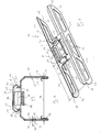
- eine perspektivische, auseinander gezogene Darstellung einer Leuchte,
- Fig. 3
- eine Seitenansicht auf einen Verbindungsbereich aufeinander fol- gender Leuchten beim Herstellen der Verbindung,
- Fig. 4
- eine perspektivische Ansicht des Verbindungsbereichs beim Her- stellen der Verbindung,
- Fig. 5
- ein Querschnitt des Lichtbands entsprechend einer Schnittlinie V in
Fig. 3 , - Fig. 6
- eine perspektivische Ansicht eines Verbinders.
- Fig. 1
- a greatly simplified side view of a section of a light band,
- Fig. 2
- a perspective, exploded view of a lamp,
- Fig. 3
- a side view of a connecting region successive lights when establishing the connection,
- Fig. 4
- a perspective view of the connection area when making the connection,
- Fig. 5
- a cross section of the light band corresponding to a section line V in
Fig. 3 . - Fig. 6
- a perspective view of a connector.
Entsprechend
Entsprechend
Im gezeigten Beispiel der
Die Tragschiene 6 ist als U-förmiger Profilkörper ausgestaltet und besitzt dementsprechend ein Basisprofil 11 und zwei davon abstehende Stegprofile 12. Das Basisprofil 11 und die Stegprofile 12 begrenzen an drei Seiten einen Innenraum 13 der Tragschiene 6 bzw. der Leuchte 2. Durch Anbringen des Geräteträgers 7 wird besagter Innenraum 13 an der dem Basisprofil 11 gegenüberliegenden vierten Seite verschlossen. Im Bereich des Basisprofils 11 kann bspw. ein Stromführungsprofil 14 angeordnet sein, das sich bandförmig im Wesentlichen über die gesamte Länge der Tragschiene 6 erstreckt und die Stromversorgung sowie die elektrische Ansteuerung elektrischer Verbraucher der Leuchte 2 ermöglicht.The
Entsprechend
Entsprechend den
Wie insbesondere
Im gezeigten bevorzugten Beispiel formen die Wandprofile 21 jeweils einen Hinterschnitt 24 aus. Dieser befindet sich in der Kammer 20 und ist dadurch vom Innenraum 13 abgewandt. Die Wandabschnitte 23 des Verbinders 16 sind im Beispiel nun so geformt, dass sie den jeweiligen Hinterschnitt 24 des zugehörigen Wandprofils 21 hintergreifen. Hierdurch ergibt sich zusätzlich ein Formschluss, der die Übertragung von Biegemomenten zwischen den miteinander verbundenen Tragschienen 6 signifikant verbessert.In the preferred example shown, the wall profiles 21 each form an undercut 24. This is located in the
Die Wandabschnitte 23 des Verbinders 16 besitzen entsprechend
Ferner können die Längsenden 26 der Stegabschnitte 17 außerdem einen Längsabstand 29 von Längsenden 30 des Basisabschnittes 18 besitzen. Durch diese Bauweise erfolgt eine seitliche Abstützung der beiden Stegabschnitte 17 nicht über deren gesamte Länge, sondern beabstandet zu ihren Längsenden 26. Hierdurch wird das Einfädeln des Verbinders 16 in die Stirnseiten der Tragschienen 6 vereinfacht. Bspw. ist dieser Längsabstand 29 zumindest gleich groß wie eine Länge 31 des Basisabschnitts 18.Furthermore, the longitudinal ends 26 of the
Um das Einführen der Stegabschnitte 17 in die Profile der Tragschienen 6 zusätzlich zu vereinfachen, können die Stegabschnitte 17 an ihren Längsenden 26, und zwar in den vom Basisabschnitt 18 entfernten Endbereichen 19 jeweils eine Einführschräge 32 aufweisen. Durch diese Einführschrägen 32 dringt beim Einsteckvorgang der Verbinder 16 zunächst außerhalb der Taschen 15 in die jeweilige Tragschiene 6 ein. Erst wenn sich durch eine bestimmte Eindringtiefe bereits eine gewisse Führungswirkung ergibt, kommen die Endbereiche 19 der Stegabschnitte 17 in Eingriff mit den Taschen 15.In order to additionally facilitate the insertion of the
Insgesamt kann der dem Einstecken des Verbinders 16 entgegengebrachte Widerstand somit gestuft werden. Zuerst dringen nur die Stegabschnitte 17 in die jeweilige Tragschiene 6 ein. Dann greifen die Endbereiche 19 der Stegabschnitte 17 in die Taschen 15 ein. Schließlich greifen die Wandabschnitte 23 in die Wandprofile 21 ein.Overall, the insertion of the connector 16 opposing resistance can thus be stepped. First, only the
Entsprechend
Entsprechend den
Entsprechend
Entsprechend den
Bei den hier gezeigten, bevorzugten Ausführungsformen ist die jeweilige Schutzleitereinrichtung 38 außerdem als Ausziehsicherung für den in die jeweilige Tragschiene 6 eingesteckten Verbinder 16 ausgestaltet. Mit anderen Worten, der in die jeweilige Tragschiene 6 eingesteckte Verbinder 16 ist in Auszugsrichtung mit Hilfe der Schutzleitereinrichtung 38 gesichert, wodurch ein Ausziehen des Verbinders 16 aus der jeweiligen Tragschiene 6 erheblich erschwert und bei den üblicherweise auftretenden Belastungen nicht möglich ist.In the preferred embodiments shown here, the respective
Die jeweilige Schutzleitereinrichtung 38 ist zweckmäßig außerdem so konzipiert, dass ihre elektrische Kontaktierung mit der jeweiligen Tragschiene 6 mit Hilfe eines Werkzeugs, z.B. mit Hilfe eines Schraubendrehers mit Flachprofil, ohne Zerstörung der Schutzleitereinrichtung 38 lösbar ist. Sofern die Schutzleitereinrichtung 38 außerdem als Ausziehsicherung konzipiert ist, kann mit Hilfe des jeweiligen Werkzeugs auch diese Ausziehsicherung gelöst werden, ohne dass dabei eine Zerstörung der Schutzleitereinrichtung 38 erfolgt.The respective
Grundsätzlich kann die jeweilige Schutzleitereinrichtung 38 integral am Verbinder 16 ausgeformt sein. Bevorzugt wird jedoch die hier vorgestellte Ausführungsform, bei welcher die jeweilige Schutzleitereinrichtung 38 durch ein bzgl. des Verbinders 16 separates Bauteil gebildet ist. Dabei ist die Schutzleitereinrichtung 38 zweckmäßig als Klammer 40 ausgestaltet, die im Folgenden auch als Schutzleiterklammer 40 bezeichnet wird. Die jeweilige Schutzleiterklammer 40 ist an den Verbinder 16 angebaut. Bspw. ist die Schutzleiterklammer 40 aus einem Federstahl hergestellt und mit einer Klemmtasche 41 ausgestattet, die in
Entsprechend
Der Verbinder 16 ist entsprechend der hier gezeigten Ausführungsformen symmetrisch aufgebaut. Bspw. ist er bzgl. einer mittig angeordneten Querschnittsebene spiegelsymmetrisch ausgebildet. Zusätzlich ist der Verbinder 16 bzgl. einer parallel zu den Stegabschnitten 17 verlaufenden Längsebene spiegelsymmetrisch aufgebaut.The connector 16 is constructed symmetrically according to the embodiments shown here. For example. it is mirror-symmetrical with respect to a centrally arranged cross-sectional plane. In addition, the connector 16 is constructed mirror-symmetrically with respect to a longitudinal plane running parallel to the
Der Verbinder 16 besitzt entsprechend
Beim gezeigten Verbinder 16 sind die Stegabschnitte 17 mit mehreren Durchbrüchen 47 versehen, so dass eine Fachwerkstruktur entsteht. Hierdurch lässt sich z.B. das Gewicht des Verbinders 16 signifikant reduzieren.In the connector 16 shown, the
Claims (13)
- Light strip with at least two lamps (2),- wherein each lamp (2) has a support rail (6) on which at least one device support (7) can be fastened,- wherein the respective support rail (6) is configured in a U-shaped manner and has a base profile (11) and also two web profiles (12),- wherein the respective web profile (12) forms a rebate (15) at an end region remote from the base profile (11) on an inner side facing the other web profile (12) in each case,- wherein at least two lamps (2), which follow one another in the longitudinal direction (3) of the light strip (1), are fixed to one another via a connector (16),- wherein the connector (16) has two web sections (17) and one base section (18) which connects the two web sections (17) to one another in such a manner that the connector (16) is configured in a U-shaped manner at least in the region of the base section (18),- wherein the connector (16) is inserted at the front into the two support rails (6) of the two lamps (2) which follow one another,- wherein outer sides of the connector (16) facing the respective support rail (6) bear against inner sides of the support rails (6) facing the connector (16),- wherein the web sections (17) of the connector (16) engage with their end regions (19) remote from the base section (18) into the rebates (15) of the web profiles (12),- wherein the base profile (11) of the respective support rail (6) forms a chamber (20) open towards the interior (13) of the support rail (6), which is delimited by two wall profiles (21) running parallel to the web profiles (12) and by a base profile (22) connecting the wall profiles (21) to one another,- wherein outwardly protruding wall sections (23) are formed on the base section (18) of the connector (16), which engage into the chamber (20) and bear with their outer sides, which face away from one another, against inner sides of the wall profiles (21) which face one another, characterised- in that the wall profiles (21) in each case form an undercut (24),- in that the wall sections (23) are shaped in such a manner that they engage behind the respective undercut (24) of the associated wall profile (21).
- Light strip according to Claim 1,
characterised
in that longitudinal ends (25) of the wall sections (23) have a longitudinal spacing (27) from longitudinal ends (26) of the web sections (17) in each case. - Light strip according to Claim 2,
characterised
in that the respective longitudinal spacing (27) is at least as large or at least twice as large as a length (28) of the wall sections (23). - Light strip according to any one of Claims 1 to 3,
characterised
in that the connector (16) and the support rails (6) are produced from sheet metal, wherein a sheet thickness (33) in the case of the connector (16) is larger than, in particular at least twice as large as, a sheet thickness (34) in the case of the support rails (6). - Light strip according to any one of Claims 1 to 4,
characterised
in that longitudinal ends (30) of the base section (18) have a longitudinal spacing (29) from longitudinal ends (26) of the web sections (17) in each case. - Light strip according to Claim 5,
characterised
in that the respective longitudinal spacing (29) is at least as large as a length (31) of the base section (18). - Light strip according to any one of Claims 1 to 6,
characterised
in that the web sections (17) have insertion chamfers (32) at their longitudinal ends (26) in the end regions (19) remote from the base section (18). - Light strip according to any one of Claims 1 to 7,
characterised- in that the base section (18) has a through opening (35),- in that the support rails (6) in each case have a break-out region (36) at their longitudinal ends in the base profile (11), which is connected via a predetermined breaking point (37) to the remaining base profile (11) and which, when it is broken out, releases a connection opening which is flush with the through opening (35) of the connector (16). - Light strip according to any one of Claims 1 to 8,
characterised
in that the connector (16) has at least one earth cable apparatus (38) for each support rail (6) in each case, which produces an electrical connection between the connector (16) and the respective support rail (6) when the connector (16) is plugged into the respective support rail (6). - Light strip according to Claim 9,
characterised
in that the respective protective earth apparatus (38) has at least one scrape level (39) which locally removes an electrically insulating coating or paintwork of the respective support rail (6) when the connector (16) is plugged in. - Light strip according to Claim 9 or 10,
characterised
in that the respective protective earth apparatus (3) is additionally configured as pull-out fuse for the connector (16) plugged into the respective support rail (6). - Light strip according to any one of Claims 9 to 11,
characterised
in that the respective protective earth apparatus (38) is configured in such a manner that its contacting with the respective support rail (6) is releasable by means of a tool without destruction of the protective earth apparatus (38). - Light strip according to any one of Claims 9 to 12,
characterised
in that the respective protective earth apparatus (38) is configured as a protective earth clip (40) which is a separate component with respect to the connector (16) and is attached to the connector (16).
Priority Applications (4)
| Application Number | Priority Date | Filing Date | Title |
|---|---|---|---|
| EP09159649A EP2249077B1 (en) | 2009-05-07 | 2009-05-07 | Light ribbon |
| AT09159649T ATE520931T1 (en) | 2009-05-07 | 2009-05-07 | LIGHT RIBBON |
| PL09159649T PL2249077T3 (en) | 2009-05-07 | 2009-05-07 | Light ribbon |
| DE202010006329U DE202010006329U1 (en) | 2009-05-07 | 2010-05-03 | trunking |
Applications Claiming Priority (1)
| Application Number | Priority Date | Filing Date | Title |
|---|---|---|---|
| EP09159649A EP2249077B1 (en) | 2009-05-07 | 2009-05-07 | Light ribbon |
Publications (2)
| Publication Number | Publication Date |
|---|---|
| EP2249077A1 EP2249077A1 (en) | 2010-11-10 |
| EP2249077B1 true EP2249077B1 (en) | 2011-08-17 |
Family
ID=40756457
Family Applications (1)
| Application Number | Title | Priority Date | Filing Date |
|---|---|---|---|
| EP09159649A Active EP2249077B1 (en) | 2009-05-07 | 2009-05-07 | Light ribbon |
Country Status (4)
| Country | Link |
|---|---|
| EP (1) | EP2249077B1 (en) |
| AT (1) | ATE520931T1 (en) |
| DE (1) | DE202010006329U1 (en) |
| PL (1) | PL2249077T3 (en) |
Cited By (1)
| Publication number | Priority date | Publication date | Assignee | Title |
|---|---|---|---|---|
| RU2680127C1 (en) * | 2018-04-02 | 2019-02-15 | Марат Габдулгазизович Бикмуллин | Led luminaire with cable tray function |
Families Citing this family (10)
| Publication number | Priority date | Publication date | Assignee | Title |
|---|---|---|---|---|
| DE202010013079U1 (en) * | 2010-12-07 | 2011-12-08 | Lite-Licht Gmbh | Connecting element for a light rail system or a mounting rail system for rod-shaped bulbs |
| DE102011017702A1 (en) * | 2011-04-28 | 2012-10-31 | Zumtobel Lighting Gmbh | Trunking system and converter unit for this |
| DE102012202148A1 (en) * | 2012-02-13 | 2013-08-14 | Trilux Gmbh & Co. Kg | Lighting system |
| DE202014100948U1 (en) * | 2014-03-03 | 2015-06-09 | Zumtobel Lighting Gmbh | Luminaire with exchangeable lighting modules |
| DE102015112838A1 (en) * | 2015-08-05 | 2017-02-09 | Selux Ag | Lighting arrangement for busbars |
| DE102018106233A1 (en) * | 2018-03-16 | 2019-09-19 | Trilux Gmbh & Co. Kg | System for the realization of a light band |
| GB2590510B (en) * | 2019-12-20 | 2022-12-07 | Thorn Lighting Ltd | Longitudinal luminaire with alignment features |
| DE202019107217U1 (en) * | 2019-12-23 | 2021-03-24 | Zumtobel Lighting Gmbh | Gear tray and light with gear tray |
| DE102020129925A1 (en) | 2020-11-12 | 2022-05-12 | Trilux Gmbh & Co. Kg | Fastening of a coupling for a light line system |
| EP4350211A1 (en) * | 2022-10-07 | 2024-04-10 | TRILUX GmbH & Co. KG | Light strip with releasable coupling |
Family Cites Families (12)
| Publication number | Priority date | Publication date | Assignee | Title |
|---|---|---|---|---|
| DE1693140U (en) * | 1953-11-30 | 1955-02-17 | Siemens Schukertwerke Ag | ARRANGEMENT FOR CONNECTING MOUNTING RAILS FOR LUMINAIRES WITH FLUORESCENT LAMPS. |
| DE1789301U (en) * | 1958-12-16 | 1959-05-27 | Hermann Jung | LONG FIELD LAMP. |
| GB930529A (en) * | 1961-03-14 | 1963-07-03 | Philips Electrical Ind Ltd | Improvements in or relating to devices for joining two channel strips end to end |
| NL298903A (en) | 1962-10-11 | |||
| DE1489555B2 (en) * | 1963-10-07 | 1976-11-18 | Trilux-Lenze Kg, 5770 Arnsberg | MOUNTING RAIL FOR ATTACHING LIGHTS |
| DE3214595C2 (en) * | 1982-04-20 | 1984-06-28 | Fränkische Leuchten GmbH, 8729 Königsberg | Connector for lights with rail-shaped parts |
| DE4300550A1 (en) * | 1993-01-12 | 1994-07-14 | Trilux Lenze Gmbh & Co Kg | Strip-lighting support rail coupler with coil springs |
| DE4409488C2 (en) * | 1994-03-19 | 1996-09-12 | Lt Licht Technik Gmbh | Rail connector |
| DE69835474T2 (en) * | 1997-04-07 | 2007-03-29 | Philips Intellectual Property & Standards Gmbh | Luminaire unit for trunking system |
| ATE341739T1 (en) * | 1997-04-09 | 2006-10-15 | Koninkl Philips Electronics Nv | LIGHT UNIT FOR LIGHT LINE SYSTEM |
| DE19840058C2 (en) | 1998-09-03 | 2003-07-17 | Regiolux Gmbh | Connection element for connecting two mounting rails |
| DE19844029A1 (en) | 1998-09-25 | 2000-05-11 | Thorn Licht Gmbh | Connecting element for rail profile elements of a line-shaped light strip |
-
2009
- 2009-05-07 EP EP09159649A patent/EP2249077B1/en active Active
- 2009-05-07 AT AT09159649T patent/ATE520931T1/en active
- 2009-05-07 PL PL09159649T patent/PL2249077T3/en unknown
-
2010
- 2010-05-03 DE DE202010006329U patent/DE202010006329U1/en not_active Expired - Lifetime
Cited By (1)
| Publication number | Priority date | Publication date | Assignee | Title |
|---|---|---|---|---|
| RU2680127C1 (en) * | 2018-04-02 | 2019-02-15 | Марат Габдулгазизович Бикмуллин | Led luminaire with cable tray function |
Also Published As
| Publication number | Publication date |
|---|---|
| PL2249077T3 (en) | 2012-01-31 |
| ATE520931T1 (en) | 2011-09-15 |
| DE202010006329U1 (en) | 2010-08-05 |
| EP2249077A1 (en) | 2010-11-10 |
Similar Documents
| Publication | Publication Date | Title |
|---|---|---|
| EP2249077B1 (en) | Light ribbon | |
| DE202013104784U1 (en) | Series device arrangement with a power bus system | |
| EP2091111B1 (en) | Contact system for light strips or lights | |
| EP2335967B1 (en) | Distancer for an electric rail system | |
| EP1853827B1 (en) | Profile connector | |
| EP0982978B1 (en) | Housing, in particular lock housing with electrical interconnections | |
| EP2264363B1 (en) | Light, end cap and light ribbon | |
| EP1475565B1 (en) | Lamp assembly | |
| DE102011053859A1 (en) | Power distributor arrangement and end cap for current-carrying profiles for this purpose | |
| EP2827051B1 (en) | Lamp | |
| DE4323370C2 (en) | Profile strip made of insulating material for holding a large number of electrical cables | |
| DE2946622C2 (en) | Device for fastening objects to a profile rail with flanges protruding outward in opposite directions | |
| DE102019114553A1 (en) | Expansion connector for a conductor rail and conductor rail | |
| WO2013131605A1 (en) | Cable-connecting component for connecting the end of one cable to the end(s) of one or more other cables | |
| DE102014102260A1 (en) | Kit for sealing the passage of cables or wires passing through a plate, as well as methods of sealing | |
| AT17765U1 (en) | Busbar component for forming an elongate busbar | |
| EP2263292B1 (en) | Apparatus for strain relief | |
| DE102006013928A1 (en) | Busbar bushing for a partition in a switchgear | |
| DE102007039171A1 (en) | Hollow body e.g. U-shaped mounting rail, mounting and inserting method for e.g. building services management system, involves removing mounting assistance element completely from hollow body during striking of concrete wall or floor | |
| DE102019126931A1 (en) | Conductor rail for lights or electrical units | |
| AT502571B1 (en) | INSTALLATION BOX | |
| DE102018124042A1 (en) | Energy chain with connection point in the joint | |
| DE2538199A1 (en) | T-Junction screw terminal for insulated through wire - has open slot and pointed screw for through wire | |
| EP4178047B1 (en) | Connector for a light strip | |
| DE102009008380A1 (en) | T-joint for facade and illuminating roof, has base body arranged at front side in bar profile, moveable clamp body mounted on connector, and pins protruding from base body and fixedly clamped against edge section of opening by clamp body |
Legal Events
| Date | Code | Title | Description |
|---|---|---|---|
| PUAI | Public reference made under article 153(3) epc to a published international application that has entered the european phase |
Free format text: ORIGINAL CODE: 0009012 |
|
| 17P | Request for examination filed |
Effective date: 20100223 |
|
| AK | Designated contracting states |
Kind code of ref document: A1 Designated state(s): AT BE BG CH CY CZ DE DK EE ES FI FR GB GR HR HU IE IS IT LI LT LU LV MC MK MT NL NO PL PT RO SE SI SK TR |
|
| GRAP | Despatch of communication of intention to grant a patent |
Free format text: ORIGINAL CODE: EPIDOSNIGR1 |
|
| GRAS | Grant fee paid |
Free format text: ORIGINAL CODE: EPIDOSNIGR3 |
|
| GRAA | (expected) grant |
Free format text: ORIGINAL CODE: 0009210 |
|
| AK | Designated contracting states |
Kind code of ref document: B1 Designated state(s): AT BE BG CH CY CZ DE DK EE ES FI FR GB GR HR HU IE IS IT LI LT LU LV MC MK MT NL NO PL PT RO SE SI SK TR |
|
| REG | Reference to a national code |
Ref country code: GB Ref legal event code: FG4D Free format text: NOT ENGLISH |
|
| REG | Reference to a national code |
Ref country code: CH Ref legal event code: EP |
|
| REG | Reference to a national code |
Ref country code: IE Ref legal event code: FG4D Free format text: LANGUAGE OF EP DOCUMENT: GERMAN |
|
| REG | Reference to a national code |
Ref country code: DE Ref legal event code: R096 Ref document number: 502009001119 Country of ref document: DE Effective date: 20111020 |
|
| REG | Reference to a national code |
Ref country code: NL Ref legal event code: VDEP Effective date: 20110817 |
|
| LTIE | Lt: invalidation of european patent or patent extension |
Effective date: 20110817 |
|
| PG25 | Lapsed in a contracting state [announced via postgrant information from national office to epo] |
Ref country code: SE Free format text: LAPSE BECAUSE OF FAILURE TO SUBMIT A TRANSLATION OF THE DESCRIPTION OR TO PAY THE FEE WITHIN THE PRESCRIBED TIME-LIMIT Effective date: 20110817 Ref country code: PT Free format text: LAPSE BECAUSE OF FAILURE TO SUBMIT A TRANSLATION OF THE DESCRIPTION OR TO PAY THE FEE WITHIN THE PRESCRIBED TIME-LIMIT Effective date: 20111219 Ref country code: LT Free format text: LAPSE BECAUSE OF FAILURE TO SUBMIT A TRANSLATION OF THE DESCRIPTION OR TO PAY THE FEE WITHIN THE PRESCRIBED TIME-LIMIT Effective date: 20110817 Ref country code: IS Free format text: LAPSE BECAUSE OF FAILURE TO SUBMIT A TRANSLATION OF THE DESCRIPTION OR TO PAY THE FEE WITHIN THE PRESCRIBED TIME-LIMIT Effective date: 20111217 Ref country code: NO Free format text: LAPSE BECAUSE OF FAILURE TO SUBMIT A TRANSLATION OF THE DESCRIPTION OR TO PAY THE FEE WITHIN THE PRESCRIBED TIME-LIMIT Effective date: 20111117 Ref country code: FI Free format text: LAPSE BECAUSE OF FAILURE TO SUBMIT A TRANSLATION OF THE DESCRIPTION OR TO PAY THE FEE WITHIN THE PRESCRIBED TIME-LIMIT Effective date: 20110817 Ref country code: NL Free format text: LAPSE BECAUSE OF FAILURE TO SUBMIT A TRANSLATION OF THE DESCRIPTION OR TO PAY THE FEE WITHIN THE PRESCRIBED TIME-LIMIT Effective date: 20110817 |
|
| REG | Reference to a national code |
Ref country code: PL Ref legal event code: T3 |
|
| PG25 | Lapsed in a contracting state [announced via postgrant information from national office to epo] |
Ref country code: GR Free format text: LAPSE BECAUSE OF FAILURE TO SUBMIT A TRANSLATION OF THE DESCRIPTION OR TO PAY THE FEE WITHIN THE PRESCRIBED TIME-LIMIT Effective date: 20111118 Ref country code: LV Free format text: LAPSE BECAUSE OF FAILURE TO SUBMIT A TRANSLATION OF THE DESCRIPTION OR TO PAY THE FEE WITHIN THE PRESCRIBED TIME-LIMIT Effective date: 20110817 Ref country code: CY Free format text: LAPSE BECAUSE OF FAILURE TO SUBMIT A TRANSLATION OF THE DESCRIPTION OR TO PAY THE FEE WITHIN THE PRESCRIBED TIME-LIMIT Effective date: 20110817 Ref country code: SI Free format text: LAPSE BECAUSE OF FAILURE TO SUBMIT A TRANSLATION OF THE DESCRIPTION OR TO PAY THE FEE WITHIN THE PRESCRIBED TIME-LIMIT Effective date: 20110817 |
|
| REG | Reference to a national code |
Ref country code: IE Ref legal event code: FD4D |
|
| PG25 | Lapsed in a contracting state [announced via postgrant information from national office to epo] |
Ref country code: SK Free format text: LAPSE BECAUSE OF FAILURE TO SUBMIT A TRANSLATION OF THE DESCRIPTION OR TO PAY THE FEE WITHIN THE PRESCRIBED TIME-LIMIT Effective date: 20110817 Ref country code: CZ Free format text: LAPSE BECAUSE OF FAILURE TO SUBMIT A TRANSLATION OF THE DESCRIPTION OR TO PAY THE FEE WITHIN THE PRESCRIBED TIME-LIMIT Effective date: 20110817 Ref country code: IE Free format text: LAPSE BECAUSE OF FAILURE TO SUBMIT A TRANSLATION OF THE DESCRIPTION OR TO PAY THE FEE WITHIN THE PRESCRIBED TIME-LIMIT Effective date: 20110817 |
|
| PG25 | Lapsed in a contracting state [announced via postgrant information from national office to epo] |
Ref country code: RO Free format text: LAPSE BECAUSE OF FAILURE TO SUBMIT A TRANSLATION OF THE DESCRIPTION OR TO PAY THE FEE WITHIN THE PRESCRIBED TIME-LIMIT Effective date: 20110817 Ref country code: EE Free format text: LAPSE BECAUSE OF FAILURE TO SUBMIT A TRANSLATION OF THE DESCRIPTION OR TO PAY THE FEE WITHIN THE PRESCRIBED TIME-LIMIT Effective date: 20110817 Ref country code: IT Free format text: LAPSE BECAUSE OF FAILURE TO SUBMIT A TRANSLATION OF THE DESCRIPTION OR TO PAY THE FEE WITHIN THE PRESCRIBED TIME-LIMIT Effective date: 20110817 |
|
| PLBE | No opposition filed within time limit |
Free format text: ORIGINAL CODE: 0009261 |
|
| STAA | Information on the status of an ep patent application or granted ep patent |
Free format text: STATUS: NO OPPOSITION FILED WITHIN TIME LIMIT |
|
| PG25 | Lapsed in a contracting state [announced via postgrant information from national office to epo] |
Ref country code: DK Free format text: LAPSE BECAUSE OF FAILURE TO SUBMIT A TRANSLATION OF THE DESCRIPTION OR TO PAY THE FEE WITHIN THE PRESCRIBED TIME-LIMIT Effective date: 20110817 |
|
| 26N | No opposition filed |
Effective date: 20120521 |
|
| REG | Reference to a national code |
Ref country code: DE Ref legal event code: R097 Ref document number: 502009001119 Country of ref document: DE Effective date: 20120521 |
|
| BERE | Be: lapsed |
Owner name: RIDI LEUCHTEN G.M.B.H. Effective date: 20120531 |
|
| PG25 | Lapsed in a contracting state [announced via postgrant information from national office to epo] |
Ref country code: HR Free format text: LAPSE BECAUSE OF FAILURE TO SUBMIT A TRANSLATION OF THE DESCRIPTION OR TO PAY THE FEE WITHIN THE PRESCRIBED TIME-LIMIT Effective date: 20120404 |
|
| PG25 | Lapsed in a contracting state [announced via postgrant information from national office to epo] |
Ref country code: MC Free format text: LAPSE BECAUSE OF NON-PAYMENT OF DUE FEES Effective date: 20120531 |
|
| PG25 | Lapsed in a contracting state [announced via postgrant information from national office to epo] |
Ref country code: MK Free format text: LAPSE BECAUSE OF FAILURE TO SUBMIT A TRANSLATION OF THE DESCRIPTION OR TO PAY THE FEE WITHIN THE PRESCRIBED TIME-LIMIT Effective date: 20110817 Ref country code: BE Free format text: LAPSE BECAUSE OF NON-PAYMENT OF DUE FEES Effective date: 20120531 |
|
| PG25 | Lapsed in a contracting state [announced via postgrant information from national office to epo] |
Ref country code: ES Free format text: LAPSE BECAUSE OF FAILURE TO SUBMIT A TRANSLATION OF THE DESCRIPTION OR TO PAY THE FEE WITHIN THE PRESCRIBED TIME-LIMIT Effective date: 20111128 |
|
| PG25 | Lapsed in a contracting state [announced via postgrant information from national office to epo] |
Ref country code: BG Free format text: LAPSE BECAUSE OF FAILURE TO SUBMIT A TRANSLATION OF THE DESCRIPTION OR TO PAY THE FEE WITHIN THE PRESCRIBED TIME-LIMIT Effective date: 20111117 |
|
| PG25 | Lapsed in a contracting state [announced via postgrant information from national office to epo] |
Ref country code: MT Free format text: LAPSE BECAUSE OF FAILURE TO SUBMIT A TRANSLATION OF THE DESCRIPTION OR TO PAY THE FEE WITHIN THE PRESCRIBED TIME-LIMIT Effective date: 20110817 |
|
| PG25 | Lapsed in a contracting state [announced via postgrant information from national office to epo] |
Ref country code: HR Free format text: LAPSE BECAUSE OF FAILURE TO SUBMIT A TRANSLATION OF THE DESCRIPTION OR TO PAY THE FEE WITHIN THE PRESCRIBED TIME-LIMIT Effective date: 20110817 |
|
| REG | Reference to a national code |
Ref country code: CH Ref legal event code: PL |
|
| PG25 | Lapsed in a contracting state [announced via postgrant information from national office to epo] |
Ref country code: LI Free format text: LAPSE BECAUSE OF NON-PAYMENT OF DUE FEES Effective date: 20130531 Ref country code: CH Free format text: LAPSE BECAUSE OF NON-PAYMENT OF DUE FEES Effective date: 20130531 |
|
| PG25 | Lapsed in a contracting state [announced via postgrant information from national office to epo] |
Ref country code: TR Free format text: LAPSE BECAUSE OF FAILURE TO SUBMIT A TRANSLATION OF THE DESCRIPTION OR TO PAY THE FEE WITHIN THE PRESCRIBED TIME-LIMIT Effective date: 20110817 |
|
| PG25 | Lapsed in a contracting state [announced via postgrant information from national office to epo] |
Ref country code: LU Free format text: LAPSE BECAUSE OF NON-PAYMENT OF DUE FEES Effective date: 20120507 |
|
| PG25 | Lapsed in a contracting state [announced via postgrant information from national office to epo] |
Ref country code: HU Free format text: LAPSE BECAUSE OF FAILURE TO SUBMIT A TRANSLATION OF THE DESCRIPTION OR TO PAY THE FEE WITHIN THE PRESCRIBED TIME-LIMIT Effective date: 20090507 |
|
| REG | Reference to a national code |
Ref country code: AT Ref legal event code: MM01 Ref document number: 520931 Country of ref document: AT Kind code of ref document: T Effective date: 20140507 |
|
| PG25 | Lapsed in a contracting state [announced via postgrant information from national office to epo] |
Ref country code: AT Free format text: LAPSE BECAUSE OF NON-PAYMENT OF DUE FEES Effective date: 20140507 |
|
| REG | Reference to a national code |
Ref country code: FR Ref legal event code: PLFP Year of fee payment: 8 |
|
| REG | Reference to a national code |
Ref country code: FR Ref legal event code: PLFP Year of fee payment: 9 |
|
| REG | Reference to a national code |
Ref country code: FR Ref legal event code: PLFP Year of fee payment: 10 |
|
| PGFP | Annual fee paid to national office [announced via postgrant information from national office to epo] |
Ref country code: FR Payment date: 20200527 Year of fee payment: 12 |
|
| PGFP | Annual fee paid to national office [announced via postgrant information from national office to epo] |
Ref country code: PL Payment date: 20200428 Year of fee payment: 12 Ref country code: GB Payment date: 20200528 Year of fee payment: 12 |
|
| GBPC | Gb: european patent ceased through non-payment of renewal fee |
Effective date: 20210507 |
|
| PG25 | Lapsed in a contracting state [announced via postgrant information from national office to epo] |
Ref country code: GB Free format text: LAPSE BECAUSE OF NON-PAYMENT OF DUE FEES Effective date: 20210507 |
|
| PG25 | Lapsed in a contracting state [announced via postgrant information from national office to epo] |
Ref country code: FR Free format text: LAPSE BECAUSE OF NON-PAYMENT OF DUE FEES Effective date: 20210531 |
|
| PG25 | Lapsed in a contracting state [announced via postgrant information from national office to epo] |
Ref country code: PL Free format text: LAPSE BECAUSE OF NON-PAYMENT OF DUE FEES Effective date: 20210507 |
|
| PGFP | Annual fee paid to national office [announced via postgrant information from national office to epo] |
Ref country code: DE Payment date: 20240529 Year of fee payment: 16 |