EP2249006B1 - Device and method for controlling the exhaust temperature of a gas turbine of a power plant - Google Patents
Device and method for controlling the exhaust temperature of a gas turbine of a power plant Download PDFInfo
- Publication number
- EP2249006B1 EP2249006B1 EP10162044.1A EP10162044A EP2249006B1 EP 2249006 B1 EP2249006 B1 EP 2249006B1 EP 10162044 A EP10162044 A EP 10162044A EP 2249006 B1 EP2249006 B1 EP 2249006B1
- Authority
- EP
- European Patent Office
- Prior art keywords
- act
- power
- tetc
- base
- calculating
- Prior art date
- Legal status (The legal status is an assumption and is not a legal conclusion. Google has not performed a legal analysis and makes no representation as to the accuracy of the status listed.)
- Active
Links
- 238000000034 method Methods 0.000 title claims description 9
- 230000007613 environmental effect Effects 0.000 claims description 36
- 230000001276 controlling effect Effects 0.000 claims description 17
- 230000001105 regulatory effect Effects 0.000 claims description 11
- 239000007789 gas Substances 0.000 description 23
- 238000002485 combustion reaction Methods 0.000 description 8
- 230000005611 electricity Effects 0.000 description 5
- 239000000446 fuel Substances 0.000 description 5
- 238000001514 detection method Methods 0.000 description 4
- MWUXSHHQAYIFBG-UHFFFAOYSA-N Nitric oxide Chemical compound O=[N] MWUXSHHQAYIFBG-UHFFFAOYSA-N 0.000 description 3
- 229910002091 carbon monoxide Inorganic materials 0.000 description 2
- UGFAIRIUMAVXCW-UHFFFAOYSA-N Carbon monoxide Chemical compound [O+]#[C-] UGFAIRIUMAVXCW-UHFFFAOYSA-N 0.000 description 1
- 239000003344 environmental pollutant Substances 0.000 description 1
- 230000010355 oscillation Effects 0.000 description 1
- 231100000719 pollutant Toxicity 0.000 description 1
- 230000000630 rising effect Effects 0.000 description 1
Images


Classifications
-
- F—MECHANICAL ENGINEERING; LIGHTING; HEATING; WEAPONS; BLASTING
- F02—COMBUSTION ENGINES; HOT-GAS OR COMBUSTION-PRODUCT ENGINE PLANTS
- F02C—GAS-TURBINE PLANTS; AIR INTAKES FOR JET-PROPULSION PLANTS; CONTROLLING FUEL SUPPLY IN AIR-BREATHING JET-PROPULSION PLANTS
- F02C9/00—Controlling gas-turbine plants; Controlling fuel supply in air- breathing jet-propulsion plants
- F02C9/16—Control of working fluid flow
- F02C9/20—Control of working fluid flow by throttling; by adjusting vanes
-
- F—MECHANICAL ENGINEERING; LIGHTING; HEATING; WEAPONS; BLASTING
- F05—INDEXING SCHEMES RELATING TO ENGINES OR PUMPS IN VARIOUS SUBCLASSES OF CLASSES F01-F04
- F05D—INDEXING SCHEME FOR ASPECTS RELATING TO NON-POSITIVE-DISPLACEMENT MACHINES OR ENGINES, GAS-TURBINES OR JET-PROPULSION PLANTS
- F05D2270/00—Control
- F05D2270/01—Purpose of the control system
- F05D2270/08—Purpose of the control system to produce clean exhaust gases
- F05D2270/083—Purpose of the control system to produce clean exhaust gases by monitoring combustion conditions
- F05D2270/0831—Purpose of the control system to produce clean exhaust gases by monitoring combustion conditions indirectly, at the exhaust
-
- F—MECHANICAL ENGINEERING; LIGHTING; HEATING; WEAPONS; BLASTING
- F05—INDEXING SCHEMES RELATING TO ENGINES OR PUMPS IN VARIOUS SUBCLASSES OF CLASSES F01-F04
- F05D—INDEXING SCHEME FOR ASPECTS RELATING TO NON-POSITIVE-DISPLACEMENT MACHINES OR ENGINES, GAS-TURBINES OR JET-PROPULSION PLANTS
- F05D2270/00—Control
- F05D2270/30—Control parameters, e.g. input parameters
- F05D2270/303—Temperature
Definitions
- the present invention relates to a device and method for controlling the exhaust temperature of a gas turbine of a power plant.
- Plants for producing electricity comprising a compressor, a combustion chamber, a gas turbine and a device for controlling the exhaust temperature of the gas turbine.
- the compressor is provided with an inlet stage defined by a plurality of adjustable inlet guide vanes, the position of which regulates the air flow at the compressor inlet.
- the device for controlling the temperature at the gas turbine exhaust comprises a module for regulating the position of the plurality of inlet guide vanes of the compressor so that the gas turbine exhaust temperature is equal to a fixed reference value, calculated a priori , and a module for regulating the supply of fuel into the combustion chamber.
- Examples of a device for controlling the temperature at the gas turbine exhaust are known from US 2006/042258 , EP 1036924 A , GB 1374871 A and the publication WATANABE M ET AL: "Development of a dynamical model for customers gas turbine generator in industrial power systems” POWER AND ENERGY CONFERENCE, 2008. PECON 2008. IEEE 2ND INTERNATIONAL, IEEE, PISCATAWAY, NJ, USA, 1 December 2008 (2008-12-01), pages 514-519, XP031412964 ISBN: 978-1-4244-2404-7 .
- the devices for controlling the gas turbine exhaust temperature thus configured are not able to optimize plant performance according to the variation of the different environmental conditions and of the type of plant in which they are installed, while keeping the pollutant emission levels under the limits of law.
- the present invention relates to a method for controlling the exhaust temperature of a gas turbine of a power plant according to claim 1.
- the present invention relates to a device for controlling the exhaust temperature of a gas turbine of a power plant according to claim 3.
- reference numeral 1 indicates a power plant for producing electricity comprising a compressor 3, a combustion chamber 4, a gas turbine 5, a generator 7 which is connected to the same shaft as the turbine 5 and transforms the mechanical power supplied by the turbine 5 into electrical power W ACT , a device 9 for controlling the exhaust temperature of turbine 5, a detection module 10, and an actuator 12.
- a variant includes plant 1 being of the combined cycle type, also comprising a steam turbo assembly, in addition to gas turbine 5 and generator 7.
- Compressor 3 is provided with an inlet stage 13 having a variable geometry.
- the inlet stage 13 comprises a plurality of inlet guide vanes (not shown for simplicity in the accompanying figures), commonly known as IGV, the inclination of which may be modified to regulate the air flow aspirated by the compressor 3 itself.
- IGV inlet guide vanes
- the inclination of the plurality of inlet guide vanes is regulated by the actuator 12, which is controlled by the device 9 for regulating the exhaust temperature of the turbine 5, as shown in detail below.
- the detection module 10 comprises a plurality of sensors (not shown for simplicity in the appended figures), which detect a plurality of parameters related to plant 1 to be fed to the device 9 for controlling the exhaust temperature of turbine 5; in particular, the detection module 10 detects the following parameters:
- the device 9 for controlling the exhaust temperature of turbine 5 comprises a FUEL regulating module 14a for regulating the supply of fuel into the combustion chamber 4 and an IGV regulation module 14b for regulating the position of the plurality of inlet guide vanes of the compressor 3.
- the FUEL regulation module 14a is configured to provide position signals to a plurality of actuators 15 (diagrammatically shown in figure 1 with one block) of respective valves (not shown) for feeding fuel to the combustion chamber 4.
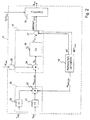
- the IGV regulation module 14b (diagrammatically indicated in figure 2 by a dash-and-dotted line) is configured to regulate the position of the plurality of inlet guide vanes of compressor 3 and comprises a first calculation module 16 (diagrammatically indicated in figure 2 by a dashed line) to calculate a reference base power in the actual environmental conditions on the basis of a reference base power value in standard environmental conditions W BASE_ISO , and on the basis of the values of actual environmental temperature T ACT and actual environmental pressure p ACT , a second calculating module 17 (diagrammatically indicated in figure 2 by a dashed line) to calculate a reference value NEWSET TETC of the exhaust temperature of the gas turbine 5 on the basis of the reference base power in the actual environmental conditions W BASE_ACT and on the basis of an actual delivered power W ACT , a control module 18 configured to send a position signal S IGV to the actuator 12 on the basis of the actual exhaust temperature TETC ACT of the turbine 5 and on the basis of the reference
- the first calculation module 16 comprises a first calculating block 20 for calculating a temperature correction factor ⁇ on the basis of the actual environmental temperature T ACT according to a function F1, a second calculating block 21 configured for calculating a pressure correction factor ⁇ on the basis of the actual environmental pressure p ACT according to a function F2, and a multiplier node 23 for multiplying the temperature correction factor ⁇ , the pressure corrector factor ⁇ , and the reference base power value W BASE_ISO in standard environmental conditions so as to obtain the reference base power W BASE_ACT in the actual environmental conditions.
- the reference base power W BASE_ISO in standard environmental conditions is a parameter determined by the parameter definition module 19 and is the maximum power, commonly named "base load", which may be delivered by the plant 1 in standard environmental conditions, i.e. at 15° C and 1013 mbars.
- the reference base power W BASE _ ACT in actual environmental conditions is calculated by the multiplier node 23 and is the maximum power which may be delivered by the plant 1 in the actual environmental conditions, i.e. at temperature T ACT and pressure p ACT .
- the functions F1 and F2 are preferably tables obtained by means of calculations based on the characteristic curve of the gas turbine 5.
- function F1 is defined by the following table: ACTUAL ENVIRONMENTAL TEMPERATURE T ACT TEMPERATURE CORRECTION FACTOR ⁇ -10 1.087 -5 1.068 5 1.033 15 1 30 0.91 40 0.837
- the actual power W ACT is preferably filtered by a filter 25 before being fed to the divider node 24 for suppressing signal interference and oscillations.
- the power ratio R P substantially expresses the actual productivity level of plant 1. If the power ratio R P is of 1, plant 1 is running at the top of its potentials, i.e. the actual delivered power W ACT is equal to the reference base power W BASE_ACT in the actual environmental conditions, which coincides with the maximum deliverable power, while if the power ratio R P is lower than 1, plant 1 is not running at the top of its potentials.
- the third calculating module 26 is configured so as to calculate the temperature correction C TETC to be added to the reference base value SET TETC of the exhaust temperature of turbine 5 on the basis of the power ratio R P .
- the third calculating module 26 is configured to calculate the temperature correction C TETC on the basis of the power ratio R P according to an experimentally determined function F3.
- function F3 is defined by the following table: POWER RATIO R P CORRECTION TEMPERATURE C TETC [°C] 0.45 5 0.55 5 0.65 2 0.8 0 1 0
- the control module 18 is configured to send the position signal S IGV to the actuator 12 on the basis of the difference between the actual exhaust temperature TETC ACT of turbine 5 detected by the detection module 10 and the reference value of the exhaust temperature NEWSET TETC calculated by the second calculation module 16.
- the control module 18 is configured to generate a position signal S IGV such as to determine a variation of the position of the inlet guide vanes which is sufficient to cancel the difference between the actual exhaust temperature TETC ACT of the turbine 5 and the exhaust temperature reference value NEWSET TETC of the gas turbine 5.
- Figure 3 shows the exhaust temperature trend of the gas turbine 5 controlled by the device 9 for controlling the exhaust temperature according to the power ratio R P .
- the exhaust temperature trend TETC of the gas turbine 5 is characterized by a rising, as compared to a constant reference value of the known solutions (not shown), to the low power ratio values R P (approximately about 0.5) so as to decrease the carbon monoxide emissions (CO), and by a lowering at a high power ratio R P (approximately about 0.9) so as to contain nitrogen oxide emissions (NOx) and prevent the onset of combustion instability phenomena. Therefore, due to the control action of the device 9, the efficiency of plant 1 is higher, especially at low power values W ACT . This results in apparent advantages especially when plant 1 is running at night, i.e. when the plant is running at minimum power.
- the exhaust temperature trend TETC of the gas turbine 5 is mainly regulated by the IGV regulation module 14b for power ratio values R P between about 0.55, which corresponds to the maximum closing position of the inlet guide vanes, and about 0.95/0.98, which corresponds to the maximum opening position of the inlet guide vanes.
Landscapes
- Engineering & Computer Science (AREA)
- Chemical & Material Sciences (AREA)
- Combustion & Propulsion (AREA)
- Physics & Mathematics (AREA)
- Fluid Mechanics (AREA)
- Mechanical Engineering (AREA)
- General Engineering & Computer Science (AREA)
- Control Of Turbines (AREA)
- Engine Equipment That Uses Special Cycles (AREA)
Description
- The present invention relates to a device and method for controlling the exhaust temperature of a gas turbine of a power plant.
- Plants for producing electricity are known, comprising a compressor, a combustion chamber, a gas turbine and a device for controlling the exhaust temperature of the gas turbine.
- The compressor is provided with an inlet stage defined by a plurality of adjustable inlet guide vanes, the position of which regulates the air flow at the compressor inlet.
- The device for controlling the temperature at the gas turbine exhaust comprises a module for regulating the position of the plurality of inlet guide vanes of the compressor so that the gas turbine exhaust temperature is equal to a fixed reference value, calculated a priori, and a module for regulating the supply of fuel into the combustion chamber.
- Examples of a device for controlling the temperature at the gas turbine exhaust are known from
US 2006/042258 ,EP 1036924 A ,GB 1374871 A - However, the devices for controlling the gas turbine exhaust temperature thus configured are not able to optimize plant performance according to the variation of the different environmental conditions and of the type of plant in which they are installed, while keeping the pollutant emission levels under the limits of law.
- It is therefore an object of the present invention to provide a method for controlling the exhaust temperature of a gas turbine of a plant for producing electricity, which is free from the prior art drawbacks identified herein; in particular, it is an object of the invention to provide a method for controlling the exhaust temperature of a gas turbine which is capable of optimizing plant performance.
- In accordance with these objects, the present invention relates to a method for controlling the exhaust temperature of a gas turbine of a power plant according to
claim 1. - It is a further object of the invention to provide a device for controlling the exhaust temperature of a gas turbine in a plant for producing electricity which is simple, cost-effective and capable of optimizing plant performance.
- In accordance with these objects, the present invention relates to a device for controlling the exhaust temperature of a gas turbine of a power plant according to claim 3.
- Further features and advantages of the present invention will be apparent from the following description of a non-limitative embodiment thereof, with reference to the figures in the accompanying drawings, in which:
-
figure 1 diagrammatically shows a power plant for producing electricity; -
figure 2 diagrammatically shows the device for controlling the exhaust temperature of a gas turbine according to the present invention; -
figure 3 diagrammatically shows the exhaust temperature trend of the gas turbine according to the variation of the ratio between the actual power delivered by the plant and a base reference power in the actual environmental conditions. - In
figure 1 ,reference numeral 1 indicates a power plant for producing electricity comprising a compressor 3, a combustion chamber 4, a gas turbine 5, agenerator 7 which is connected to the same shaft as the turbine 5 and transforms the mechanical power supplied by the turbine 5 into electrical power WACT, adevice 9 for controlling the exhaust temperature of turbine 5, adetection module 10, and anactuator 12. - A variant (not shown) includes
plant 1 being of the combined cycle type, also comprising a steam turbo assembly, in addition to gas turbine 5 andgenerator 7. - Compressor 3 is provided with an
inlet stage 13 having a variable geometry. Theinlet stage 13 comprises a plurality of inlet guide vanes (not shown for simplicity in the accompanying figures), commonly known as IGV, the inclination of which may be modified to regulate the air flow aspirated by the compressor 3 itself. - In particular, the inclination of the plurality of inlet guide vanes is regulated by the
actuator 12, which is controlled by thedevice 9 for regulating the exhaust temperature of the turbine 5, as shown in detail below. - The
detection module 10 comprises a plurality of sensors (not shown for simplicity in the appended figures), which detect a plurality of parameters related toplant 1 to be fed to thedevice 9 for controlling the exhaust temperature of turbine 5; in particular, thedetection module 10 detects the following parameters: - actual environmental temperature TACT, detected at the inlet of compressor 3;
- actual environmental pressure pACT detected at the inlet of compressor 3;
- actual exhaust temperature TETCACT of turbine 5;
- actual power WACT delivered by
plant 1, preferably detected at the terminals of thegenerator 7 by means of a wattmeter. - The
device 9 for controlling the exhaust temperature of turbine 5 comprises a FUEL regulatingmodule 14a for regulating the supply of fuel into the combustion chamber 4 and anIGV regulation module 14b for regulating the position of the plurality of inlet guide vanes of the compressor 3. - The FUEL
regulation module 14a is configured to provide position signals to a plurality of actuators 15 (diagrammatically shown infigure 1 with one block) of respective valves (not shown) for feeding fuel to the combustion chamber 4. - With reference to
figure 2 , theIGV regulation module 14b (diagrammatically indicated infigure 2 by a dash-and-dotted line) is configured to regulate the position of the plurality of inlet guide vanes of compressor 3 and comprises a first calculation module 16 (diagrammatically indicated infigure 2 by a dashed line) to calculate a reference base power in the actual environmental conditions on the basis of a reference base power value in standard environmental conditions WBASE_ISO, and on the basis of the values of actual environmental temperature TACT and actual environmental pressure pACT, a second calculating module 17 (diagrammatically indicated infigure 2 by a dashed line) to calculate a reference value NEWSETTETC of the exhaust temperature of the gas turbine 5 on the basis of the reference base power in the actual environmental conditions WBASE_ACT and on the basis of an actual delivered power WACT, acontrol module 18 configured to send a position signal SIGV to theactuator 12 on the basis of the actual exhaust temperature TETCACT of the turbine 5 and on the basis of the reference temperature value NEWSETTETC calculated by thesecond calculation module 17, and aparameter definition module 19. - The
first calculation module 16 comprises a first calculatingblock 20 for calculating a temperature correction factor α on the basis of the actual environmental temperature TACT according to a function F1, a second calculatingblock 21 configured for calculating a pressure correction factor β on the basis of the actual environmental pressure pACT according to a function F2, and amultiplier node 23 for multiplying the temperature correction factor α, the pressure corrector factor β, and the reference base power value WBASE_ISO in standard environmental conditions so as to obtain the reference base power WBASE_ACT in the actual environmental conditions. - The reference base power WBASE_ISO in standard environmental conditions is a parameter determined by the
parameter definition module 19 and is the maximum power, commonly named "base load", which may be delivered by theplant 1 in standard environmental conditions, i.e. at 15° C and 1013 mbars. - The reference base power WBASE_ACT in actual environmental conditions is calculated by the
multiplier node 23 and is the maximum power which may be delivered by theplant 1 in the actual environmental conditions, i.e. at temperature TACT and pressure pACT. - The functions F1 and F2 are preferably tables obtained by means of calculations based on the characteristic curve of the gas turbine 5.
- In the example described and illustrated herein, function F1 is defined by the following table:
ACTUAL ENVIRONMENTAL TEMPERATURE TACT TEMPERATURE CORRECTION FACTOR α -10 1.087 -5 1.068 5 1.033 15 1 30 0.91 40 0.837 - The
second calculation module 16 comprises adivider node 24 for calculating a power ratio RP between the actual power WACT delivered by theplant 1 and the reference base power WBASE_ACT in the actual environmental conditions, athird calculation module 26 for calculating a temperature correction CTETC and a fourth calculatingmodule 27 for calculating the reference value NEWSETTETC in accordance with the following formula:
- CTETC is the temperature correction calculated by the third calculating
module 26; - SETTETC is the reference base value of the exhaust temperature of turbine 5 at the maximum power which may be delivered by the
plant 1 determined by theparameter definition module 19 on the basis of requirements which are to be ensured, such as for example requirements related to power, efficiency, exhaust temperature of turbine 5 and combustion stability; - ΔT is a temperature offset adapted to avoid the onset of instability phenomena within the combustion chamber 4, normally indicated by the term "humming", and is determined by the
parameter definition module 19. - The actual power WACT is preferably filtered by a
filter 25 before being fed to thedivider node 24 for suppressing signal interference and oscillations. - The power ratio RP substantially expresses the actual productivity level of
plant 1. If the power ratio RP is of 1,plant 1 is running at the top of its potentials, i.e. the actual delivered power WACT is equal to the reference base power WBASE_ACT in the actual environmental conditions, which coincides with the maximum deliverable power, while if the power ratio RP is lower than 1,plant 1 is not running at the top of its potentials. - The
third calculating module 26 is configured so as to calculate the temperature correction CTETC to be added to the reference base value SETTETC of the exhaust temperature of turbine 5 on the basis of the power ratio RP. In particular, the third calculatingmodule 26 is configured to calculate the temperature correction CTETC on the basis of the power ratio RP according to an experimentally determined function F3. - In the example described and illustrated herein, function F3 is defined by the following table:
POWER RATIO RP CORRECTION TEMPERATURE CTETC [°C] 0.45 5 0.55 5 0.65 2 0.8 0 1 0 - The
control module 18 is configured to send the position signal SIGV to theactuator 12 on the basis of the difference between the actual exhaust temperature TETCACT of turbine 5 detected by thedetection module 10 and the reference value of the exhaust temperature NEWSETTETC calculated by thesecond calculation module 16. In particular, thecontrol module 18 is configured to generate a position signal SIGV such as to determine a variation of the position of the inlet guide vanes which is sufficient to cancel the difference between the actual exhaust temperature TETCACT of the turbine 5 and the exhaust temperature reference value NEWSETTETC of the gas turbine 5. -
Figure 3 shows the exhaust temperature trend of the gas turbine 5 controlled by thedevice 9 for controlling the exhaust temperature according to the power ratio RP. - In particular, the exhaust temperature trend TETC of the gas turbine 5 is characterized by a rising, as compared to a constant reference value of the known solutions (not shown), to the low power ratio values RP (approximately about 0.5) so as to decrease the carbon monoxide emissions (CO), and by a lowering at a high power ratio RP (approximately about 0.9) so as to contain nitrogen oxide emissions (NOx) and prevent the onset of combustion instability phenomena. Therefore, due to the control action of the
device 9, the efficiency ofplant 1 is higher, especially at low power values WACT. This results in apparent advantages especially whenplant 1 is running at night, i.e. when the plant is running at minimum power. - In detail, the exhaust temperature trend TETC of the gas turbine 5 is mainly regulated by the
IGV regulation module 14b for power ratio values RP between about 0.55, which corresponds to the maximum closing position of the inlet guide vanes, and about 0.95/0.98, which corresponds to the maximum opening position of the inlet guide vanes. - It is finally apparent that changes and variations may be made to the method and device described herein, without departing from the scope of the appended claims.
Claims (3)
- Method for controlling the exhaust temperature of a gas turbine (5) of a power plant (1) comprising the step of regulating the position cf a plurality of inlet guide vanes of a compressor (3) of the plant (1) in such a way that an actual exhaust temperature (TETCACT) of the gas turbine (5) is equal to a reference value (NEWSETTETC); and the step of calculating the reference value (NEWSETTETC) on the basis of actual environmental conditions (TACT, pACT), on the basis of an actual power (WACT) delivered by the plant (1) and on the basis of a first reference base power (WBASE_ISO) in standard environmental conditions; the step of calculating the reference value (NEWSETTETC) comprising the steps of: calculating a second reference base power (WBASE_ACT) in actual environmental conditions; and calculating the reference value (NEWSETTETC) on the basis of a ratio (RP) between the actual power (WACT) and the second reference base power (WBASE_ACT); wherein the step of calculating the second reference base power (WBRASE_ACT) comprises detecting an actual environmental temperature (TACT); the method being characterized in that the step of calculating the second reference base power (WBASE_ACT) comprises the steps of:- detecting an actual environmental pressure (pACT);- calculating the first reference base power (WBASE_ISO) in standard environmental conditions;- calculating the second reference base power (WBASE_ACT) in actual environmental conditions on the basis of the first reference base power (WBASE_ISO), of the actual environmental temperature (TACT) and of the actual environmental pressure (pPACT).
- Method according to Claim 1, wherein the step of calculating the reference value (NEWSETTETC) comprises the steps of:- calculating a temperature correction (CTETC) on the basis of the ratio (RP) between the actual power (WACT) and the second reference base power (WBASE_ACT);- calculating the reference value (NEWSETTETC) accorcing to the following formula:
 CTETC is the temperature correction;SETTETC is a reference base value of the exhaust temperature of the gas turbine (5) at the maximum power deliverable by the plant (1);ΔT is a temperature offset.
 - Device for controlling the exhaust temperature of a gas turbine (5) of a power plant (1) comprising regulating means (18) for regulating the position of a plurality of inlet guide vanes of a compressor (3) of a plant (1) in such a way that the actual exhaust temperature (TETACT) of the gas turbine (5) 1s equal to a reference value (NEWSETTETC); and calculating means (16, 17) for calculating the reference value (NEWSETTETC) on the basis of actual environmental conditions (TACT, PACT), on the basis of an actual power (WACT) delivered by the plant (1) and on the basis of a first reference base power (WBASE_ISO) in standard environmental conditions; wherein the calculating means (16, 17) comprise a first calculating module (16) for calculating a second reference base power (WBASE_ACT) in actual environmental conditions and a second calculating module (17) for calculating the reference value (NEWSETTETC) on the basis of a ratio (RP) between the actual power (WACT) and the second reference base power (WBASE_ACT); the device being characterized in that the first calculating module (16) is configured to calculate the second reference base power (WBASE_ACT) in actual environmental conditions on the basis of the first reference base power (WBASE_ISO) in standard environmental conditions and on the basis of the values of actual environmental temperature (TACT) and actual environmental pressure (pACT).
Applications Claiming Priority (1)
| Application Number | Priority Date | Filing Date | Title |
|---|---|---|---|
| IT000766A ITMI20090766A1 (en) | 2009-05-06 | 2009-05-06 | DEVICE AND METHOD TO CHECK THE TEMPERATURE AT THE DISCHARGE OF A GAS TURBINE OF AN ENERGY PRODUCTION PLANT |
Publications (2)
| Publication Number | Publication Date |
|---|---|
| EP2249006A1 EP2249006A1 (en) | 2010-11-10 |
| EP2249006B1 true EP2249006B1 (en) | 2016-03-30 |
Family
ID=41566217
Family Applications (1)
| Application Number | Title | Priority Date | Filing Date |
|---|---|---|---|
| EP10162044.1A Active EP2249006B1 (en) | 2009-05-06 | 2010-05-05 | Device and method for controlling the exhaust temperature of a gas turbine of a power plant |
Country Status (2)
| Country | Link |
|---|---|
| EP (1) | EP2249006B1 (en) |
| IT (1) | ITMI20090766A1 (en) |
Families Citing this family (2)
| Publication number | Priority date | Publication date | Assignee | Title |
|---|---|---|---|---|
| EP2907990A1 (en) * | 2014-02-18 | 2015-08-19 | Siemens Aktiengesellschaft | Method for operating a gas turbine installation, and the same |
| US10961919B2 (en) | 2017-08-29 | 2021-03-30 | Pratt & Whitney Canada Corp | Corrected parameters control logic for variable geometry mechanisms |
Family Cites Families (4)
| Publication number | Priority date | Publication date | Assignee | Title |
|---|---|---|---|---|
| BE790124A (en) * | 1971-10-15 | 1973-04-16 | Westinghouse Electric Corp | IMPROVEMENTS TO A DIGITAL COMPUTER CONTROL SYSTEM OF AN INDUSTRIAL GAS TURBINE APPLIANCE |
| US6164057A (en) * | 1999-03-16 | 2000-12-26 | General Electric Co. | Gas turbine generator having reserve capacity controller |
| US7269953B2 (en) * | 2004-08-27 | 2007-09-18 | Siemens Power Generation, Inc. | Method of controlling a power generation system |
| EP2185868A1 (en) * | 2007-08-01 | 2010-05-19 | Ansaldo Energia S.P.A. | Device and method for regulating the exhaust temperature of a gas turbine |
-
2009
- 2009-05-06 IT IT000766A patent/ITMI20090766A1/en unknown
-
2010
- 2010-05-05 EP EP10162044.1A patent/EP2249006B1/en active Active
Non-Patent Citations (1)
| Title |
|---|
| None * |
Also Published As
| Publication number | Publication date |
|---|---|
| ITMI20090766A1 (en) | 2010-11-07 |
| EP2249006A1 (en) | 2010-11-10 |
Similar Documents
| Publication | Publication Date | Title |
|---|---|---|
| US6912856B2 (en) | Method and system for controlling gas turbine by adjusting target exhaust temperature | |
| EP1553343B1 (en) | Method for reduction of combustor dynamic pressure during operation of gas turbine engines | |
| US6637205B1 (en) | Electric assist and variable geometry turbocharger | |
| CN106062343B (en) | Control system and method for controlling gas-turbine unit during transition | |
| JP5550592B2 (en) | Gas turbine control device | |
| EP2738371A2 (en) | A system and method for operating a gas turbine in a turndown mode | |
| CN105849392B (en) | The control method of the control device of gas turbine, gas turbine and gas turbine | |
| EP2823168A1 (en) | Gas turbine engine configured to shape power output | |
| KR101913975B1 (en) | Control device, system, and control method, and power control device, gas turbine, and power control method | |
| CN110139980B (en) | Method for operating a wind turbine, device for controlling a wind turbine and corresponding wind turbine | |
| EP2249006B1 (en) | Device and method for controlling the exhaust temperature of a gas turbine of a power plant | |
| JP4796015B2 (en) | Gas turbine operation control device and operation control method | |
| JP5037529B2 (en) | How to operate a combustion facility | |
| EP2185868A1 (en) | Device and method for regulating the exhaust temperature of a gas turbine | |
| RU2601320C1 (en) | Power control method of combined-cycle plants and apparatus for its implementation | |
| JP2013160154A (en) | Gas turbine control apparatus, method and program and power plant employing the same | |
| EP3047129B1 (en) | Method of controlling emissions of a gas turbine plant and gas turbine plant | |
| US10408135B2 (en) | Method for operating a gas turbine below the nominal power thereof | |
| DiCampli et al. | Grid stability: Gas turbines for primary reserve | |
| US12031490B2 (en) | System and method for non-model based control utilizing turbine exit mach number surrogate | |
| EP2527737B1 (en) | Control method for controlling the supply of fuel to a gas turbine plant and gas turbine plant | |
| WO2015063735A1 (en) | Control method and device for controlling a gas turbine plant for electrical energy production | |
| CN112627989A (en) | System and method for controlling exhaust temperature and nitrogen oxide concentration of small gas turbine | |
| CN117570469A (en) | Combustion monitoring and evaluating method for automatic combustion adjusting system of F-level combustion engine |
Legal Events
| Date | Code | Title | Description |
|---|---|---|---|
| PUAI | Public reference made under article 153(3) epc to a published international application that has entered the european phase |
Free format text: ORIGINAL CODE: 0009012 |
|
| AK | Designated contracting states |
Kind code of ref document: A1 Designated state(s): AL AT BE BG CH CY CZ DE DK EE ES FI FR GB GR HR HU IE IS IT LI LT LU LV MC MK MT NL NO PL PT RO SE SI SK SM TR |
|
| AX | Request for extension of the european patent |
Extension state: BA ME RS |
|
| 17P | Request for examination filed |
Effective date: 20110510 |
|
| 17Q | First examination report despatched |
Effective date: 20130904 |
|
| GRAP | Despatch of communication of intention to grant a patent |
Free format text: ORIGINAL CODE: EPIDOSNIGR1 |
|
| INTG | Intention to grant announced |
Effective date: 20150914 |
|
| GRAS | Grant fee paid |
Free format text: ORIGINAL CODE: EPIDOSNIGR3 |
|
| GRAA | (expected) grant |
Free format text: ORIGINAL CODE: 0009210 |
|
| INTG | Intention to grant announced |
Effective date: 20160129 |
|
| AK | Designated contracting states |
Kind code of ref document: B1 Designated state(s): AL AT BE BG CH CY CZ DE DK EE ES FI FR GB GR HR HU IE IS IT LI LT LU LV MC MK MT NL NO PL PT RO SE SI SK SM TR |
|
| REG | Reference to a national code |
Ref country code: GB Ref legal event code: FG4D |
|
| REG | Reference to a national code |
Ref country code: CH Ref legal event code: EP |
|
| REG | Reference to a national code |
Ref country code: AT Ref legal event code: REF Ref document number: 785672 Country of ref document: AT Kind code of ref document: T Effective date: 20160415 |
|
| REG | Reference to a national code |
Ref country code: IE Ref legal event code: FG4D |
|
| REG | Reference to a national code |
Ref country code: DE Ref legal event code: R096 Ref document number: 602010031582 Country of ref document: DE |
|
| REG | Reference to a national code |
Ref country code: CH Ref legal event code: NV Representative=s name: RENTSCH PARTNER AG, CH |
|
| REG | Reference to a national code |
Ref country code: LT Ref legal event code: MG4D |
|
| PG25 | Lapsed in a contracting state [announced via postgrant information from national office to epo] |
Ref country code: HR Free format text: LAPSE BECAUSE OF FAILURE TO SUBMIT A TRANSLATION OF THE DESCRIPTION OR TO PAY THE FEE WITHIN THE PRESCRIBED TIME-LIMIT Effective date: 20160330 Ref country code: NO Free format text: LAPSE BECAUSE OF FAILURE TO SUBMIT A TRANSLATION OF THE DESCRIPTION OR TO PAY THE FEE WITHIN THE PRESCRIBED TIME-LIMIT Effective date: 20160630 Ref country code: GR Free format text: LAPSE BECAUSE OF FAILURE TO SUBMIT A TRANSLATION OF THE DESCRIPTION OR TO PAY THE FEE WITHIN THE PRESCRIBED TIME-LIMIT Effective date: 20160701 Ref country code: FI Free format text: LAPSE BECAUSE OF FAILURE TO SUBMIT A TRANSLATION OF THE DESCRIPTION OR TO PAY THE FEE WITHIN THE PRESCRIBED TIME-LIMIT Effective date: 20160330 |
|
| REG | Reference to a national code |
Ref country code: NL Ref legal event code: MP Effective date: 20160330 |
|
| REG | Reference to a national code |
Ref country code: AT Ref legal event code: MK05 Ref document number: 785672 Country of ref document: AT Kind code of ref document: T Effective date: 20160330 |
|
| PG25 | Lapsed in a contracting state [announced via postgrant information from national office to epo] |
Ref country code: LT Free format text: LAPSE BECAUSE OF FAILURE TO SUBMIT A TRANSLATION OF THE DESCRIPTION OR TO PAY THE FEE WITHIN THE PRESCRIBED TIME-LIMIT Effective date: 20160330 Ref country code: SE Free format text: LAPSE BECAUSE OF FAILURE TO SUBMIT A TRANSLATION OF THE DESCRIPTION OR TO PAY THE FEE WITHIN THE PRESCRIBED TIME-LIMIT Effective date: 20160330 Ref country code: BE Free format text: LAPSE BECAUSE OF NON-PAYMENT OF DUE FEES Effective date: 20160531 Ref country code: LV Free format text: LAPSE BECAUSE OF FAILURE TO SUBMIT A TRANSLATION OF THE DESCRIPTION OR TO PAY THE FEE WITHIN THE PRESCRIBED TIME-LIMIT Effective date: 20160330 |
|
| PG25 | Lapsed in a contracting state [announced via postgrant information from national office to epo] |
Ref country code: NL Free format text: LAPSE BECAUSE OF FAILURE TO SUBMIT A TRANSLATION OF THE DESCRIPTION OR TO PAY THE FEE WITHIN THE PRESCRIBED TIME-LIMIT Effective date: 20160330 |
|
| PG25 | Lapsed in a contracting state [announced via postgrant information from national office to epo] |
Ref country code: PL Free format text: LAPSE BECAUSE OF FAILURE TO SUBMIT A TRANSLATION OF THE DESCRIPTION OR TO PAY THE FEE WITHIN THE PRESCRIBED TIME-LIMIT Effective date: 20160330 Ref country code: IS Free format text: LAPSE BECAUSE OF FAILURE TO SUBMIT A TRANSLATION OF THE DESCRIPTION OR TO PAY THE FEE WITHIN THE PRESCRIBED TIME-LIMIT Effective date: 20160730 Ref country code: EE Free format text: LAPSE BECAUSE OF FAILURE TO SUBMIT A TRANSLATION OF THE DESCRIPTION OR TO PAY THE FEE WITHIN THE PRESCRIBED TIME-LIMIT Effective date: 20160330 |
|
| PG25 | Lapsed in a contracting state [announced via postgrant information from national office to epo] |
Ref country code: SM Free format text: LAPSE BECAUSE OF FAILURE TO SUBMIT A TRANSLATION OF THE DESCRIPTION OR TO PAY THE FEE WITHIN THE PRESCRIBED TIME-LIMIT Effective date: 20160330 Ref country code: PT Free format text: LAPSE BECAUSE OF FAILURE TO SUBMIT A TRANSLATION OF THE DESCRIPTION OR TO PAY THE FEE WITHIN THE PRESCRIBED TIME-LIMIT Effective date: 20160801 Ref country code: RO Free format text: LAPSE BECAUSE OF FAILURE TO SUBMIT A TRANSLATION OF THE DESCRIPTION OR TO PAY THE FEE WITHIN THE PRESCRIBED TIME-LIMIT Effective date: 20160330 Ref country code: ES Free format text: LAPSE BECAUSE OF FAILURE TO SUBMIT A TRANSLATION OF THE DESCRIPTION OR TO PAY THE FEE WITHIN THE PRESCRIBED TIME-LIMIT Effective date: 20160330 Ref country code: CZ Free format text: LAPSE BECAUSE OF FAILURE TO SUBMIT A TRANSLATION OF THE DESCRIPTION OR TO PAY THE FEE WITHIN THE PRESCRIBED TIME-LIMIT Effective date: 20160330 Ref country code: SK Free format text: LAPSE BECAUSE OF FAILURE TO SUBMIT A TRANSLATION OF THE DESCRIPTION OR TO PAY THE FEE WITHIN THE PRESCRIBED TIME-LIMIT Effective date: 20160330 Ref country code: AT Free format text: LAPSE BECAUSE OF FAILURE TO SUBMIT A TRANSLATION OF THE DESCRIPTION OR TO PAY THE FEE WITHIN THE PRESCRIBED TIME-LIMIT Effective date: 20160330 |
|
| PG25 | Lapsed in a contracting state [announced via postgrant information from national office to epo] |
Ref country code: BE Free format text: LAPSE BECAUSE OF FAILURE TO SUBMIT A TRANSLATION OF THE DESCRIPTION OR TO PAY THE FEE WITHIN THE PRESCRIBED TIME-LIMIT Effective date: 20160330 Ref country code: LU Free format text: LAPSE BECAUSE OF FAILURE TO SUBMIT A TRANSLATION OF THE DESCRIPTION OR TO PAY THE FEE WITHIN THE PRESCRIBED TIME-LIMIT Effective date: 20160505 |
|
| REG | Reference to a national code |
Ref country code: DE Ref legal event code: R097 Ref document number: 602010031582 Country of ref document: DE |
|
| PG25 | Lapsed in a contracting state [announced via postgrant information from national office to epo] |
Ref country code: DK Free format text: LAPSE BECAUSE OF FAILURE TO SUBMIT A TRANSLATION OF THE DESCRIPTION OR TO PAY THE FEE WITHIN THE PRESCRIBED TIME-LIMIT Effective date: 20160330 |
|
| PLBE | No opposition filed within time limit |
Free format text: ORIGINAL CODE: 0009261 |
|
| STAA | Information on the status of an ep patent application or granted ep patent |
Free format text: STATUS: NO OPPOSITION FILED WITHIN TIME LIMIT |
|
| REG | Reference to a national code |
Ref country code: IE Ref legal event code: MM4A |
|
| GBPC | Gb: european patent ceased through non-payment of renewal fee |
Effective date: 20160630 |
|
| REG | Reference to a national code |
Ref country code: FR Ref legal event code: ST Effective date: 20170131 |
|
| 26N | No opposition filed |
Effective date: 20170103 |
|
| PG25 | Lapsed in a contracting state [announced via postgrant information from national office to epo] |
Ref country code: FR Free format text: LAPSE BECAUSE OF NON-PAYMENT OF DUE FEES Effective date: 20160531 |
|
| PG25 | Lapsed in a contracting state [announced via postgrant information from national office to epo] |
Ref country code: SI Free format text: LAPSE BECAUSE OF FAILURE TO SUBMIT A TRANSLATION OF THE DESCRIPTION OR TO PAY THE FEE WITHIN THE PRESCRIBED TIME-LIMIT Effective date: 20160330 Ref country code: GB Free format text: LAPSE BECAUSE OF NON-PAYMENT OF DUE FEES Effective date: 20160630 Ref country code: IE Free format text: LAPSE BECAUSE OF NON-PAYMENT OF DUE FEES Effective date: 20160505 |
|
| PGFP | Annual fee paid to national office [announced via postgrant information from national office to epo] |
Ref country code: CH Payment date: 20170529 Year of fee payment: 8 |
|
| REG | Reference to a national code |
Ref country code: CH Ref legal event code: PCAR Free format text: NEW ADDRESS: BELLERIVESTRASSE 203 POSTFACH, 8034 ZUERICH (CH) |
|
| PG25 | Lapsed in a contracting state [announced via postgrant information from national office to epo] |
Ref country code: CY Free format text: LAPSE BECAUSE OF FAILURE TO SUBMIT A TRANSLATION OF THE DESCRIPTION OR TO PAY THE FEE WITHIN THE PRESCRIBED TIME-LIMIT Effective date: 20160330 Ref country code: HU Free format text: LAPSE BECAUSE OF FAILURE TO SUBMIT A TRANSLATION OF THE DESCRIPTION OR TO PAY THE FEE WITHIN THE PRESCRIBED TIME-LIMIT; INVALID AB INITIO Effective date: 20100505 |
|
| PG25 | Lapsed in a contracting state [announced via postgrant information from national office to epo] |
Ref country code: MT Free format text: LAPSE BECAUSE OF NON-PAYMENT OF DUE FEES Effective date: 20160531 Ref country code: TR Free format text: LAPSE BECAUSE OF FAILURE TO SUBMIT A TRANSLATION OF THE DESCRIPTION OR TO PAY THE FEE WITHIN THE PRESCRIBED TIME-LIMIT Effective date: 20160330 Ref country code: MK Free format text: LAPSE BECAUSE OF FAILURE TO SUBMIT A TRANSLATION OF THE DESCRIPTION OR TO PAY THE FEE WITHIN THE PRESCRIBED TIME-LIMIT Effective date: 20160330 Ref country code: MC Free format text: LAPSE BECAUSE OF FAILURE TO SUBMIT A TRANSLATION OF THE DESCRIPTION OR TO PAY THE FEE WITHIN THE PRESCRIBED TIME-LIMIT Effective date: 20160330 |
|
| PG25 | Lapsed in a contracting state [announced via postgrant information from national office to epo] |
Ref country code: BG Free format text: LAPSE BECAUSE OF FAILURE TO SUBMIT A TRANSLATION OF THE DESCRIPTION OR TO PAY THE FEE WITHIN THE PRESCRIBED TIME-LIMIT Effective date: 20160330 |
|
| PG25 | Lapsed in a contracting state [announced via postgrant information from national office to epo] |
Ref country code: AL Free format text: LAPSE BECAUSE OF FAILURE TO SUBMIT A TRANSLATION OF THE DESCRIPTION OR TO PAY THE FEE WITHIN THE PRESCRIBED TIME-LIMIT Effective date: 20160330 |
|
| REG | Reference to a national code |
Ref country code: CH Ref legal event code: PL |
|
| PG25 | Lapsed in a contracting state [announced via postgrant information from national office to epo] |
Ref country code: CH Free format text: LAPSE BECAUSE OF NON-PAYMENT OF DUE FEES Effective date: 20180531 Ref country code: LI Free format text: LAPSE BECAUSE OF NON-PAYMENT OF DUE FEES Effective date: 20180531 |
|
| PGFP | Annual fee paid to national office [announced via postgrant information from national office to epo] |
Ref country code: IT Payment date: 20231124 Year of fee payment: 14 |
|
| P01 | Opt-out of the competence of the unified patent court (upc) registered |
Effective date: 20240430 |
|
| PGFP | Annual fee paid to national office [announced via postgrant information from national office to epo] |
Ref country code: DE Payment date: 20240517 Year of fee payment: 15 |