EP2248945B1 - Hydrostatic supporting element - Google Patents
Hydrostatic supporting element Download PDFInfo
- Publication number
- EP2248945B1 EP2248945B1 EP20100159650 EP10159650A EP2248945B1 EP 2248945 B1 EP2248945 B1 EP 2248945B1 EP 20100159650 EP20100159650 EP 20100159650 EP 10159650 A EP10159650 A EP 10159650A EP 2248945 B1 EP2248945 B1 EP 2248945B1
- Authority
- EP
- European Patent Office
- Prior art keywords
- valve body
- supporting element
- hydrostatic
- capillary
- pressure
- Prior art date
- Legal status (The legal status is an assumption and is not a legal conclusion. Google has not performed a legal analysis and makes no representation as to the accuracy of the status listed.)
- Not-in-force
Links
Images

Classifications
-
- D—TEXTILES; PAPER
- D21—PAPER-MAKING; PRODUCTION OF CELLULOSE
- D21G—CALENDERS; ACCESSORIES FOR PAPER-MAKING MACHINES
- D21G1/00—Calenders; Smoothing apparatus
- D21G1/02—Rolls; Their bearings
- D21G1/0206—Controlled deflection rolls
- D21G1/0213—Controlled deflection rolls with deflection compensation means acting between the roller shell and its supporting member
- D21G1/022—Controlled deflection rolls with deflection compensation means acting between the roller shell and its supporting member the means using fluid pressure
-
- F—MECHANICAL ENGINEERING; LIGHTING; HEATING; WEAPONS; BLASTING
- F16—ENGINEERING ELEMENTS AND UNITS; GENERAL MEASURES FOR PRODUCING AND MAINTAINING EFFECTIVE FUNCTIONING OF MACHINES OR INSTALLATIONS; THERMAL INSULATION IN GENERAL
- F16C—SHAFTS; FLEXIBLE SHAFTS; ELEMENTS OR CRANKSHAFT MECHANISMS; ROTARY BODIES OTHER THAN GEARING ELEMENTS; BEARINGS
- F16C13/00—Rolls, drums, discs, or the like; Bearings or mountings therefor
- F16C13/02—Bearings
- F16C13/022—Bearings supporting a hollow roll mantle rotating with respect to a yoke or axle
- F16C13/024—Bearings supporting a hollow roll mantle rotating with respect to a yoke or axle adjustable for positioning, e.g. radial movable bearings for controlling the deflection along the length of the roll mantle
- F16C13/026—Bearings supporting a hollow roll mantle rotating with respect to a yoke or axle adjustable for positioning, e.g. radial movable bearings for controlling the deflection along the length of the roll mantle by fluid pressure
- F16C13/028—Bearings supporting a hollow roll mantle rotating with respect to a yoke or axle adjustable for positioning, e.g. radial movable bearings for controlling the deflection along the length of the roll mantle by fluid pressure with a plurality of supports along the length of the roll mantle, e.g. hydraulic jacks
-
- F—MECHANICAL ENGINEERING; LIGHTING; HEATING; WEAPONS; BLASTING
- F16—ENGINEERING ELEMENTS AND UNITS; GENERAL MEASURES FOR PRODUCING AND MAINTAINING EFFECTIVE FUNCTIONING OF MACHINES OR INSTALLATIONS; THERMAL INSULATION IN GENERAL
- F16C—SHAFTS; FLEXIBLE SHAFTS; ELEMENTS OR CRANKSHAFT MECHANISMS; ROTARY BODIES OTHER THAN GEARING ELEMENTS; BEARINGS
- F16C32/00—Bearings not otherwise provided for
- F16C32/06—Bearings not otherwise provided for with moving member supported by a fluid cushion formed, at least to a large extent, otherwise than by movement of the shaft, e.g. hydrostatic air-cushion bearings
- F16C32/0603—Bearings not otherwise provided for with moving member supported by a fluid cushion formed, at least to a large extent, otherwise than by movement of the shaft, e.g. hydrostatic air-cushion bearings supported by a gas cushion, e.g. an air cushion
- F16C32/0614—Bearings not otherwise provided for with moving member supported by a fluid cushion formed, at least to a large extent, otherwise than by movement of the shaft, e.g. hydrostatic air-cushion bearings supported by a gas cushion, e.g. an air cushion the gas being supplied under pressure, e.g. aerostatic bearings
- F16C32/0622—Bearings not otherwise provided for with moving member supported by a fluid cushion formed, at least to a large extent, otherwise than by movement of the shaft, e.g. hydrostatic air-cushion bearings supported by a gas cushion, e.g. an air cushion the gas being supplied under pressure, e.g. aerostatic bearings via nozzles, restrictors
-
- F—MECHANICAL ENGINEERING; LIGHTING; HEATING; WEAPONS; BLASTING
- F16—ENGINEERING ELEMENTS AND UNITS; GENERAL MEASURES FOR PRODUCING AND MAINTAINING EFFECTIVE FUNCTIONING OF MACHINES OR INSTALLATIONS; THERMAL INSULATION IN GENERAL
- F16C—SHAFTS; FLEXIBLE SHAFTS; ELEMENTS OR CRANKSHAFT MECHANISMS; ROTARY BODIES OTHER THAN GEARING ELEMENTS; BEARINGS
- F16C32/00—Bearings not otherwise provided for
- F16C32/06—Bearings not otherwise provided for with moving member supported by a fluid cushion formed, at least to a large extent, otherwise than by movement of the shaft, e.g. hydrostatic air-cushion bearings
- F16C32/0662—Details of hydrostatic bearings independent of fluid supply or direction of load
- F16C32/0666—Details of hydrostatic bearings independent of fluid supply or direction of load of bearing pads
Definitions
- the invention relates to a hydrostatic support element which is suitable for exerting a supporting force on the inside of the roll shell in a deflection roll in a rotationally fixed yoke axially passing through a rotating roll shell, wherein hydrostatic pockets of the hydrostatic support element in each case via at least one throttle or capillary be supplied with pressurized fluid.
- the invention relates to a deflection adjustment roll with a support element.
- a support element and such a roller are for example in the EP 1279767 B1 described.
- support sources or support elements are used, which are supplied with oil pressure by a supply line. By this oil pressure, the respective support source is pressed against the rotating roll shell. Since the piston area of the support source is smaller than the hydrostatic pocket surface facing the roll shell, a lower pocket oil pressure is established. The pressure difference between piston pressure and pocket pressure determines the volume flow which flows through the capillaries connected between the pocket surface and the piston surface. Thus, the respective volume flow adjusts to a support sources in dependence on the piston pressure.
- the support sources are individually subjected to an oil pressure.
- the height of the oil pressures for example, via an online profile thickness measurement of Web regulated.
- the aim of the invention is to provide an improved and more reliable support member of the type mentioned above, wherein the volume flow of at least a portion of a respective hydrostatic pocket supplied pressurized fluid in dependence on the piston pressure of the respective support member remains variable.
- the throttle or capillary is arranged spirally or helically. Due to the spirai- or helical throttle or capillary, the effective overall length is increased enormously with limited height of the support elements.
- the capillary can have a much larger cross section at the same flow resistance compared to conventional capillaries. The risk of clogging such a throttle or capillary is almost impossible.
- the capillary is provided in the form of a groove in a valve body. Such a groove is particularly easy to produce.
- valve body is arranged axially displaceably in a valve body guide.
- acting as a throttle length of the capillary can be adjusted.
- the volume flow via at least one variable throttle in dependence on the piston pressure of the respective support element is variable.
- valve body is displaceable in the valve body guide between a first and a second end position positions. In the first end position the throttle is opened as far as possible and in the second end position the throttle is closed as far as possible. So you have two defined flow values, from which one can make the precise control of the flow to the hydrostatic pockets.
- the helical capillary is introduced into the inner wall of the valve body guide.
- the valve body can represent a simple cylinder.
- the valve body is loaded by a spring with a predetermined spring stiffness in such a way that it is in the first end position when the piston is depressurized.
- a spring characteristic can be selected, which ensures a safe control of the valve.
- the pressure in the pressure chamber of the cylinder / piston unit of the support element acts on the valve body in the direction of the second Endiagenposition.
- the embodiment of an end face of the valve body as a printing surface is particularly easy to design. The Ventilkör is then moved by the pressure from the pressure chamber below the support element piston against the spring force in its valve body guide.
- the hydrostatic pockets can be supplied in particular via the pressure chamber of the respective support element, which means that the throttles or capillaries are provided between this pressure chamber and the relevant hydrostatic pockets.
- a respective variable throttle can thus be connected in particular between the pressure chamber of the relevant support element and the associated hydrostatic pocket.
- the valve body guide has a pressure fluid supply line between the first and the second end position of the valve body. From the supply line, the pressurized fluid is passed through the capillary into the hydrostatic pocket. Depending on the position of the valve body, the length of the capillary is different, If the pressure in the piston of the support element is large, so is the length of the helical capillary to the hydrostatic bag long. The volume flow is correspondingly lower.
- the variable throttle is designed so that the volume flow in question is increasingly larger with increasingly smaller pressures in the pressure chamber and vice versa.
- the pressurized fluid supply line from a pressure chamber in which the support element piston is pressurized is fed. This way, only one has to Pressure fluid main feed per support element done.
- a deflection adjustment roller is claimed with the hydrostatic support element according to the invention.
- FIG. 1 shows a schematic sectional partial view of an exemplary embodiment of a hydrostatic support element 1 of a deflection set roller 10, which can serve for the treatment of a material web such as in particular a paper or board web in a gap formed with Gegenfiamba (not shown).
- the deflection adjustment roll 10 comprises a circumferential roll shell 12, a roll shell 12 axially passing through a rotationally fixed yoke 14 and a plurality of in the direction of the roll axis successively arranged on the yoke 14 hydrostatic support elements 1, of which in the FIG. 1 only one can be seen.
- the support elements 1 are each formed by a pressure fluid-actuated cylinder / piston unit which exerts on the inside of the roll shell 12 a respective supporting force.
- the support elements 1 can be controlled individually and / or in groups be, resulting in corresponding, in the direction of the roll axis successive Watzentikzonen.
- the pressure chamber 18 of a respective support member 1 is acted upon via a channel 20 provided in the yoke 14 with pressurized fluid.
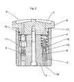
- FIG. 2 finally shows the support element piston 2 in an enlarged view FIG. 1 which is not shown in detail there.
- the shell-side Hydrostatiktaschen 7 are each supplied via at least one throttle or capillary 11, 17 with pressurized fluid. In the present case, these throttles 11, 17 are connected between the hydrostatic pockets 7 and the pressure chamber 18.
- a respective support element 1 has, for example, four hydrostatic pockets 7.
- the volume flow of the pressure fluid supplied to a respective hydrostatic pocket 7 is variable in dependence on the piston pressure prevailing in the pressure chamber 18 of the support element 1.
- the relevant volume flows can be varied in particular such that an at least substantially constant mixing temperature results in the interior of the roll.
- the respective volume flow is varied via a respective variable throttle 11 as a function of the piston pressure.
- the variable throttles 11 are connected between the pressure chamber 18 and the respective associated hydrostatic pocket 7.
- each hydrostatic pocket 7 each one Fixed throttle 17, ie non-variable capillary, which is connected in each case with an opening into the pressure chamber 18 of the support member 16 variable throttle 11 in series.
- variable throttles 11 may each comprise a valve or be designed as a valve. In the present case, these valves are designed so that the volume flow in question is increasingly larger with increasingly smaller piston pressures and vice versa.
- variable throttles 11 are controlled by a piston body acted upon by the piston 3, which is guided in a bore which serves as a valve body guide 13.
- the valve body 3 is loaded by a supported spring 4 in the direction of the pressure chamber 18 and acted upon by a pressure surface 19 by the piston pressure in the pressure chamber 18 against the force of the spring 4.
- About the pressure surface 19 of the valve body 3 according to the respective pressurization in the closing direction or in the opening direction of the valve-like variable throttles 11 is movable.
- valve body 3 moves more or less within a path between a first and a second end position 15, 16.
- the valve body 3 has a helical circumferential groove 5. This groove 5 forms a capillary 11 between the valve body 3 and the valve body guide 13th
- the helical groove 5 may also be introduced in the wall of the valve body guide 13.
- the length of the capillary 11 is advantageously very large due to the helical or spiral arrangement of the groove 5.
- the diameter of the capillary 11 may be quite large, relative to prior art designs. At the same time, however, this means less risk of clogging due to particles entrained in the pressurized oil.
- connection point of the supply line 6 into the capillary 11 is in the region of the lower and the upper end position 15, 16 of the valve body 3.
- the end of the feed channel 6 is formed in the embodiment as an annular undercut in the valve body guide 13.
- the capillary is therefore relatively long and offers a high flow resistance. This increases the friction of the shell on the surface of the support element head 9, which leads to a heating of the area. This is desirable because the pressure effect on the web to be treated is increased by the thermal expansion of the shell at this point.
- the capillary provides a small flow resistance when the pressure in the pressure chamber 18 is low. This means that a larger volume flow of the pressure fluid passes into the hydrostatic pockets 7 and for provides better cooling.
- variable throttle 11 may in particular be designed and / or controlled so that it has a maximum length at piston pressures above a predetermined upper limit and thus at least substantially completely closed and / or at piston pressures below a predetermined lower limit value has a minimum length and at least essentially completely open.
- variable throttle fixed chokes are connected in parallel or in series.
- variable effect of the throttle 11 which preferably takes place via the opening stroke of a valve body to be fine tuned.
Landscapes
- Engineering & Computer Science (AREA)
- General Engineering & Computer Science (AREA)
- Mechanical Engineering (AREA)
- Physics & Mathematics (AREA)
- Fluid Mechanics (AREA)
- Rolls And Other Rotary Bodies (AREA)
- Magnetic Bearings And Hydrostatic Bearings (AREA)
Description
Die Erfindung betrifft ein hydrostatisches Stützelement, das geeignet ist, in einer Durchbiegungseinstellwalze in einem einen umlaufenden Walzenmantel axial durchsetzenden drehfesten Joch als eine druckfluidbetätigte Zylinder/Kolben-Einheit eine Stützkraft auf die Innenseite des Walzenmantels auszuüben, wobei Hydrostatiktaschen des hydrostatischen Stützelements jeweils über wenigstens eine Drossel oder Kapillare mit Druckfluid versorgt werden. Außerdem betrifft die Erfindung eine Durchbiegungseinstellwalze mit einem Stützelement. Ein Stützelement und eine derartige Walze sind beispielsweise in der
In Durchbiegungseinstell oder Durchbiegungsausgleichswalzen kommen Stützquellen oder Stützelemente zum Einsatz, die durch eine Versorgungsleitung mit Öldruck beaufschlagt werden. Durch diesen Öldruck wird die jeweilige Stützquelle gegen den rotierenden Walzenmantel gepresst. Da die Kolbenfläche der Stützquelle kleiner ist als die zum Walzenmantel weisende Hydrostatiktaschenfläche, stellt sich ein geringerer Taschenöldruck ein. Die Druckdifferenz zwischen Kolbendruck und Taschendruck bestimmt den Volumenstrom, der über die zwischen die Taschenfläche und die Kolbenfläche geschalteten Kapillaren fließt. Somit stellt sich der jeweilige Volumenstrom an einer Stützquellen in Abhängigkeit vom Kolbendruck ein.In deflection adjustment or deflection compensating rollers, support sources or support elements are used, which are supplied with oil pressure by a supply line. By this oil pressure, the respective support source is pressed against the rotating roll shell. Since the piston area of the support source is smaller than the hydrostatic pocket surface facing the roll shell, a lower pocket oil pressure is established. The pressure difference between piston pressure and pocket pressure determines the volume flow which flows through the capillaries connected between the pocket surface and the piston surface. Thus, the respective volume flow adjusts to a support sources in dependence on the piston pressure.
Zur individuellen Profilkorrektur, d.h. insbesondere zur Korrektur bestimmter Eigenschaftsquerprofile, der durch einen Walzenspalt laufenden Warenbahn, insbesondere Papier- oder Kartonbahn, werden die Stützquellen einzeln mit einem Öldruck beaufschlagt. Die Höhe der Öldrücke wird beispielsweise über eine online-Profildickenmessung der Warenbahn geregelt.For individual profile correction, ie, in particular for the correction of certain property transverse profiles, of the material web running through a nip, in particular paper or board web, the support sources are individually subjected to an oil pressure. The height of the oil pressures, for example, via an online profile thickness measurement of Web regulated.
In Abhängigkeit von den jeweils erforderlichen Profilkorrekturen kann es zu großen Differenzen zwischen den Öldrücken der verschiedenen Stützquellen kommen (z.B. von 3,5 bis 90 bar von Stützquelle zu Stützquellen). Dies führt, wie bereits angedeutet, zu Volumenstromdifferenzen an den Stützquellen. Zwischen dem rotierenden Walzenmantel und den Stützquellen entsteht durch die Ölscherung in Abhängigkeit von der Mantelgeschwindigkeit und der Ölspalthöhe, die wieder vom Volumenstrom, der Öltemperatur und dem Taschendruck abhängig ist. Reibung. Infolge der großen Druckunterschiede ergibt sich somit von einer Stützquelle zur anderen eine unterschiedlich hohe Reibleistung, die sich in Temperaturdifferenzen am Walzenmantel auswirkt. Diese Temperaturdifferenzen wirken sich wieder auf die Form des Walzenmantels aus und bringen somit einen das erzeugte Streckenlastprofil der Durchbiegungseinstellwalze beeinflussende Rückkopplungseffekt mit sich.Depending on the required profile corrections, there may be large differences between the oil pressures of the various support sources (e.g., from 3.5 to 90 bar from source to support sources). This leads, as already indicated, to volume flow differences at the support sources. Between the rotating roll shell and the support sources created by the oil shear as a function of the shell speed and the oil gap height, which is again dependent on the flow, the oil temperature and the pocket pressure. Friction. As a result of the large pressure differences thus results from a support source to another a different high friction, which affects the temperature differences on the roll shell. These temperature differences have an effect on the shape of the roll shell and thus bring with it a feedback effect influencing the generated line load profile of the deflection set roll.
Da sich bei einer Druckentlastung an einer Stützquelle ein geringerer Volumenstrom einstellt, ergibt sich an dieser Stützquelle trotz einer betragsmäßig geringeren Reibleistung als bei höheren Drücken eine höhere Temperatur. Eine höhere Temperatur führt nun aber zu einer Ausdehnung des Walzenmantels, die sich in einer Streckenlasterhöhung im Walzenspalt auswirkt. Die Temperaturentwicklung wirkt sich also gegenläufig zur gewünschten Druckentlastung aus und ist somit unerwünscht. In Einzelfällen kann dies sogar zu einer Instabilität im Regelverhalten führen.Since setting a lower flow rate at a pressure relief at a support source, results in a higher temperature at this support source despite a lower amount of friction power than at higher pressures. However, a higher temperature leads to an expansion of the roll mantle, which has an effect in increasing the line load in the nip. The temperature development thus counteracts the desired pressure relief and is therefore undesirable. In some cases, this can even lead to instability in the control behavior.
Diese Situation ist bereits in der
In den Ausgestaltungsbeispielen der
Ziel der Erfindung ist es, eine verbessertes und betriebssichereres Stützelement der eingangs genannten Art zu schaffen, wobei der Volumenstrom zumindest eines Teils des einer jeweiligen Hydrostatiktasche zugeführten Druckfluids in Abhängigkeit vom Kolbendruck des jeweiligen Stützelements variierbar bleibt.The aim of the invention is to provide an improved and more reliable support member of the type mentioned above, wherein the volume flow of at least a portion of a respective hydrostatic pocket supplied pressurized fluid in dependence on the piston pressure of the respective support member remains variable.
Diese Aufgabe wird nach der Erfindung dadurch gelöst, dass die Drossel oder Kapillare spiral- oder schraubenlinienförmig angeordnet ist. Durch die spirai- oder schraubenlinienförmige Drossel oder Kapillare wird die wirksame Gesamtlänge bei begrenzter Höhe des Stützelemente enorm vergrößert. Die käpillare kann bei dem gleichen Strömungswiderstand verglichen mit herkömmlichen Kapillaren einen deutlich größeren Querschnitt besitzen. Die Verstopfungsgefahr einer solchen Drossel oder Kapillare ist dadurch nahezu ausgeschlossen.This object is achieved according to the invention in that the throttle or capillary is arranged spirally or helically. Due to the spirai- or helical throttle or capillary, the effective overall length is increased enormously with limited height of the support elements. The capillary can have a much larger cross section at the same flow resistance compared to conventional capillaries. The risk of clogging such a throttle or capillary is almost impossible.
Es ist von Vorteil, wenn die Kapillare in Form einer Nut in einem Ventilkörper vorgesehen ist. Eine solche Nut ist besonders einfach herstellbar.It is advantageous if the capillary is provided in the form of a groove in a valve body. Such a groove is particularly easy to produce.
Vorzugsweise ist der Ventilkörper in einer Ventilkörperführung axial verschiebbar angeordnet. Auf diese Weise kann die als Drossel wirkende Länge der Kapillare eingestellt werden. Dadurch ist der Volumenstrom über wenigstens eine variable Drossel in Abhängigkeit vom Kolbendruck des jeweiligen Stützelementes variierbar.Preferably, the valve body is arranged axially displaceably in a valve body guide. In this way, the acting as a throttle length of the capillary can be adjusted. As a result, the volume flow via at least one variable throttle in dependence on the piston pressure of the respective support element is variable.
Bei einer bevorzugten praktischen Ausführungsform ist der Ventilkörper in der Ventilkörperführung zwischen einer ersten und einer zweiten Endlagenpositionen verschiebbar. In der ersten Endlagenposition ist die Drossel so weit wir möglich geöffnet und in der zweiten Endlagenposition ist die Drossel so weit wie möglich geschlossen. Man hat also zwei definierte Durchflusswerte, von denen ausgehend man die genaue Regelung des Volumenstroms zu den Hydrostatiktaschen vornehmen kann.In a preferred practical embodiment, the valve body is displaceable in the valve body guide between a first and a second end position positions. In the first end position the throttle is opened as far as possible and in the second end position the throttle is closed as far as possible. So you have two defined flow values, from which one can make the precise control of the flow to the hydrostatic pockets.
In einer alternativen bevorzugten Ausgestaltung ist die schraubenlinienförmige Kapillare in die Innenwandung der Ventilkörperführung eingebracht. In diesem Fall ist zwar der Aufwand zur Herstellung der Kapillare etwas größer, dafür kann der Ventilkörper aber einen einfachen Zylinder darstellen.In an alternative preferred embodiment, the helical capillary is introduced into the inner wall of the valve body guide. In this case, although the effort to make the capillary is slightly larger, but the valve body can represent a simple cylinder.
Mit Vorteil ist der Ventilkörper über eine Feder mit vorbestimmter Federsteifigkeit derart belastet, dass er sich bei drucklosem Kolben in der ersten Endlagenposition befindet. Durch eine für den Fachmann einfache Auswahl kann eine Federkennlinie vorgewählt werden, die eine sichere Steuerung des Ventils gewährleistet.Advantageously, the valve body is loaded by a spring with a predetermined spring stiffness in such a way that it is in the first end position when the piston is depressurized. By a simple choice for the expert, a spring characteristic can be selected, which ensures a safe control of the valve.
Beverzugt wirkt der Druck im Druckraum der Zylinder/Kolben-Einheit des Stützelementes auf den Ventilkörper in Richtung der zweiten Endiagenposition. Die Ausgestaltung einer Stirnfläche des Ventilkörpers als Druckfläche ist besonders einfach zu gestalten. Der Ventilkör per ist dann durch den Druck aus dem Druckraum unterhalb des Stützelementkolbens gegen die Federkraft in seiner Ventilkörperführung bewegbar.By default, the pressure in the pressure chamber of the cylinder / piston unit of the support element acts on the valve body in the direction of the second Endiagenposition. The embodiment of an end face of the valve body as a printing surface is particularly easy to design. The Ventilkör is then moved by the pressure from the pressure chamber below the support element piston against the spring force in its valve body guide.
Die Hydrostatiktaschen können insbesondere über den Druckraum des jeweiligen Stützelements versorgt sein, was bedeutet, dass die Drosseln bzw. Kapillaren zwischen diesem Druckraum und den betreffenden Hydrostatiktaschen vorgesehen sind. Eine jeweilige variable Drossel kann somit insbesondere zwischen den Druckraum des betreffenden Stützelements und die zugeordnete Hydrostatiktasche geschaltet sein.The hydrostatic pockets can be supplied in particular via the pressure chamber of the respective support element, which means that the throttles or capillaries are provided between this pressure chamber and the relevant hydrostatic pockets. A respective variable throttle can thus be connected in particular between the pressure chamber of the relevant support element and the associated hydrostatic pocket.
Es ist von Vorteil, wenn die Ventilkörperführung zwischen der ersten und der zweiten Endposition des Ventilkörpers eine Druckfluid-Zuführleitung aufweist. Von der Zufuhrleitung wird das Druckfluid durch die Kapillare in die Hydrostatiktasche geführt. Je nach Stellung des Ventilkörpers ist die Länge der Kapillare verschieden, Ist der Druck im Kolben des Stützelementes groß, so ist auch die Länge der schraubenlinienförmigen Kapillare bis zur Hydrostatiktasche lang. Entsprechend geringer wird der Volumenstrom. Bei einer bevorzugten praktischen Ausführungsform ist die variable Drossel so ausgeführt, dass der betreffende Volumenstrom mit zunehmend kleiner werdenden Drücken im Druckraum zunehmend größer wird und umgekehrt. Durch eine entsprechende Ansteuerung der variablen Drosseln kann somit die Mischtemperatur wie in der
Besonders vorteilhaft ist vorgesehen, dass die Druckfluid-Zuführleitung aus einem Druckraum, in dem auch der Stützelementkolben mit Druck beaufschlagbar ist, gespeist wird. Auf diese Weise muss nur eine Druckfluid-Haupteinspeisung pro Stützelement erfolgen.Particularly advantageous is provided that the pressurized fluid supply line from a pressure chamber in which the support element piston is pressurized, is fed. This way, only one has to Pressure fluid main feed per support element done.
Des Weiteren wird eine Durchbiegungseinstellwalze mit dem erfindungsgemäßen hydrostatischen Stützelement beansprucht.Furthermore, a deflection adjustment roller is claimed with the hydrostatic support element according to the invention.
Die Erfindung wird im Folgenden anhand von Ausführungsbeispielen unter Bezugnahme auf die Zeichnung näher erläutert; in dieser zeigen:
-
Figur 1 -
Figur 2 einen Schnitt durch den Stützelementkolben eines erfindungsgemäßen Stützelementes.
-
FIG. 1 a schematic sectional partial view of an embodiment of a deflection adjustment according to the invention and -
FIG. 2 a section through the support element piston of a support element according to the invention.
Die Durchbiegungseinstellwalze 10 umfasst einen umlaufenden Walzenmantel 12, ein den Walzenmantel 12 axial durchsetzendes drehfestes Joch 14 und mehrere in Richtung der Walzenachse hintereinander am Joch 14 angeordnete hydrostatische Stützelemente 1, von denen in der
Die Stützelemente 1 sind jeweils durch eine druckfluidbetätigte Zylinder/Kolben-Einheit gebildet, die auf die Innenseite des Walzenmantels 12 eine jeweilige Stützkraft ausübt.The
Die Stützelemente 1 können einzeln und/oder gruppenweise ansteuerbar sein, wodurch sich entsprechende, in Richtung der Walzenachse aufeinanderfolgende Watzendruckzonen ergeben.The
Der Druckraum 18 eines jeweiligen Stützelements 1 ist über einen im Joch 14 vorgesehenen Kanal 20 mit Druckfluid beaufschlagbar.The
Im vorliegenden Fall besitzt ein Jeweiliges Stützelement 1 beilspielsweise jeweils vier Hydrostatiktaschen 7.In the present case, a
Der Volumenstrom des einer jeweiligen Hydrostatiktasche 7 zugeführten Druckfluids ist in Abhängigkeit vom in dem Druckraum 18 des Stützelements 1 vorherrschenden Kolbendruck variierbar. Dabei sind bei den verschiedenen Stützelementen 1 die betreffenden Volumenströme insbesondere so variierbar, dass sich eine zumindest im Wesentlichen konstante Mischtemperatur im Walzeninnern ergibt.The volume flow of the pressure fluid supplied to a respective hydrostatic pocket 7 is variable in dependence on the piston pressure prevailing in the
Dazu wird der jeweilige Volumenstrom über eine jeweilige variable Drossel 11 in Abhängigkeit vom Kolbendruck variiert. Wie anhand der
Im vorliegenden Fall mündet in jede Hydrostatiktasche 7 jeweils eine Festdrossel 17, d.h. nicht variable Kapillare, die jeweils mit einer in den Druckraum 18 des Stützelements 16 mündenden variablen Drossel 11 in Reihe geschaltet ist.In the present case flows into each hydrostatic pocket 7 each one Fixed
Die variablen Drosseln 11 können jeweils ein Ventil umfassen oder als Ventil ausgeführt sein. Im vorliegenden Fall sind diese Ventile so ausgeführt, dass der betreffende Volumenstrom mit zunehmend kleiner werdenden Kolbendrücken zunehmend größer wird und umgekehrt.The variable throttles 11 may each comprise a valve or be designed as a valve. In the present case, these valves are designed so that the volume flow in question is increasingly larger with increasingly smaller piston pressures and vice versa.
Im vorliegenden Fall sind die variablen Drosseln 11 durch einen vom Kolbendruck beaufschlagten Ventilkörper 3 gesteuert, der in einer Bohrung, die als Ventilkörpertührung 13 dient, geführt ist. Der Ventilkörper 3 ist durch eine abgestützte Feder 4 in Richtung des Druckraums 18 belastet und über eine Druckfläche 19 durch den Kolbendruck im Druckraum 18 entgegen der Kraft der Feder 4 beaufschlagbar. Über die Druckfläche 19 ist der Ventilkörper 3 entsprechend der jeweiligen Druckbeaufschlagung in Schließrichtung oder in Öffnungsrichtung der ventilartigen variablen Drosseln 11 bewegbar.In the present case, the variable throttles 11 are controlled by a piston body acted upon by the piston 3, which is guided in a bore which serves as a
Je nach Größe des Drucks im Kolbenraum 18 bewegt sich der Ventilkörper 3 mehr oder weniger innerhalb einer Wegstrecke zwischen einer ersten und einer zweiten Endlagenposition 15, 16. Der Ventilkörper 3 besitzt eine schraubenförmig umlaufende Nut 5. Diese Nut 5 bildet eine Kapillare 11 zwischen dem Ventilkörper 3 und der Ventilkörperführung 13.Depending on the size of the pressure in the
Alternativ kann die schraubenförmige Nut 5 auch in der Wandung der Ventilkörperführung 13 eingebracht sein.Alternatively, the
In jedem Fall ist in vorteilhafter Weise durch die schrauben- oder spiralförmige Anordnung der Nut 5 die Länge der Kapillare 11 sehr groß. Um einen benötigten Strömungswiderstand für das Drucköl zu erreichen, kann der Durchmesser der Kapillare 11 recht groß sein, relativ gesehen zu Ausführungen in Stand der Technik. Das bedeutet aber gleichzeitig eine geringere Gefahr von Verstopfungen durch im Drucköl mitgeführte Partikel.In any case, the length of the capillary 11 is advantageously very large due to the helical or spiral arrangement of the
Der Anschlusspunkt der Zuführleitung 6 in die Kapillare 11 befindet sich im Bereich der unteren und der oberen Endlagenposition 15, 16 des Ventilkörpers 3. Zur Vergleichmäßigung des Druckfluid-Übergangs ist das Ende des Zuführkanals 6 in dem Ausführungsbeispiel als ringförmiger Freistich in der Ventilkörperführung 13 ausgebildet. Durch eine Verschiebung des Ventilkörpers aufgrund des Drucks Im Kolbenraum 18 verändert sich auch die wirksame Länge der Kapillare 11 und somit der Volumenstrom des Druckfluids zu der wenigstens einen Hydrostatiktasche 7. In der
Bei einem hohen Druck im Druckraum 18 ist die Kapillare demnach relativ lang und bietet einen hohen Strömungswiderstand. Dadurch erhöht sich die Reibung des Mantels an der Oberfläche des Stützelementkopfes 9, was zu einer Erwärmung des Bereiches führt. Dies ist gewünscht, weil sich durch die Wärmeausdehnung des Mantels an dieser Stelle die Druckwirkung auf die zu behandelnde Bahn vergrößert wird.At a high pressure in the
Umgekehrt bietet die Kapillare einen kleinen Strömungswiderstand, wenn der Druck im Druckraum 18 gering ist. Das bedeutet, dass ein größerer Volumenstrom des Druckfluids in die Hydrostatiktaschen 7 gelangt und für eine bessere Kühlung sorgt.Conversely, the capillary provides a small flow resistance when the pressure in the
Die variable Drossel 11 kann insbesondere so ausgeführt und/oder angesteuert sein, dass sie bei Kolbendrücken oberhalb eines vorgebbare oberen Grenzwertes eine maximale Länge hat und somit zumindest im Wesentlichen ganz geschlossen und/oder bei Kolbendrücken unterhalb eines vorgebbaren unteren Grenzwerts einen minimale Länge hat und zumindest im Wesentlichen ganz geöffnet ist.The variable throttle 11 may in particular be designed and / or controlled so that it has a maximum length at piston pressures above a predetermined upper limit and thus at least substantially completely closed and / or at piston pressures below a predetermined lower limit value has a minimum length and at least essentially completely open.
Von den dargestellten Ausführungsformen kann in vielfacher Hinsicht abgewichen werden, ohne den Grundgedanken der Erfindung zu verlassen. Insbesondere kann es sinnvoll sein, wenn mit der variablen Drossel Festdrosseln parallel oder in Reihe geschaltet sind. Durch eine solche geschaltete Fest- oder Konstantdrossel kann die variable Wirkung der Drossel 11, die vorzugsweise über den Öffnungsweg eines Ventilkörpers erfolgt, fein abgestimmt werden.From the illustrated embodiments may be departed from in many ways, without departing from the spirit of the invention. In particular, it may be useful if the variable throttle fixed chokes are connected in parallel or in series. By such a switched fixed or constant throttle, the variable effect of the throttle 11, which preferably takes place via the opening stroke of a valve body to be fine tuned.
- 11
- Hydrostatisches StützelementHydrostatic support element
- 22
- StützelementkolbenSupport element piston
- 33
- Ventilkörpervalve body
- 44
- Federfeather
- 55
- Nutgroove
- 66
- Zuführleitungfeed
- 77
- HydroslatiktascheHydroslatiktasche
- 88th
- Grundkörperbody
- 99
- Kopfhead
- 1010
- Durchbiegungseinstellwalzedeflection
- 1111
- (variable) Drossel, Kapillare(variable) throttle, capillary
- 1212
- Walzenmantelroll shell
- 1313
- VentilkörperführungValve body guide
- 1414
- Jochyoke
- 1515
- erste Endlagenpositionfirst end position
- 1616
- zweite Endlagenpositionsecond end position
- 1717
- Festdrosselfixed throttle
- 1818
- Druckraumpressure chamber
- 1919
- Druckflächeprint area
- 2020
- Kanalchannel
Claims (10)
- Hydrostatic supporting element which, in a controlled deflection roll (10), in a rotationally fixed yoke (14) passing axially through a revolving roll shell (12), is suitable as a cylinder/piston unit actuated by compressed fluid to exert a supporting force on the inner side of the roll shell (12), hydrostatic pockets (7) of the hydrostatic supporting element (1) in each case being supplied with pressurized fluid via at least one throttle or capillary (11, 17),
characterized in that
the throttle or capillary (11) is arranged in the form of a helix. - Hydrostatic supporting element according to Claim 1,
characterized in that
the capillary is provided in the form of a groove (5) in a valve body (3). - Hydrostatic supporting element according to Claim 2,
characterized in that
the valve body (3) is arranged such that it can be displaced axially in a valve body guide (13). - Hydrostatic supporting element according to Claim 3,
characterized in that
the valve body (3) can be displaced in the valve body guide (13) between a first and a second end position (15, 60). - Hydrostatic supporting element according to Claim 1,
characterized in that
the helical capillary (11) is introduced into the wall of the valve body guide (13). - Hydrostatic supporting element according to either of Claims 4 and 5,
characterized in that
the valve body (3) is loaded by a spring (4) with a predetermined spring stiffness in such a way that, when the piston is unpressurized, the said valve body is located in the first end position (15). - Hydrostatic supporting element according to one of Claims 4 to 6,
characterized in that
the pressure in the cylinder/piston unit acts on the valve body (3) in the direction of the second end position (16). - Hydrostatic supporting element according to Claims 4 to 7,
characterized in that
the valve body (3) has a pressurized fluid feed line (6) between the first and the second end position (15, 16) of the valve body (3). - Hydrostatic supporting element according to Claim 8,
characterized in that
the pressurized fluid feed line (6) is fed from a pressure chamber, in which the supporting element piston (2) can also be pressurized. - Controlled deflection roll,
characterized in that
it comprises at least one hydrostatic supporting element (1) according to one of Claims 1 to 9.
Applications Claiming Priority (1)
| Application Number | Priority Date | Filing Date | Title |
|---|---|---|---|
| DE200910002627 DE102009002627A1 (en) | 2009-04-24 | 2009-04-24 | Hydrostatic support element |
Publications (2)
| Publication Number | Publication Date |
|---|---|
| EP2248945A1 EP2248945A1 (en) | 2010-11-10 |
| EP2248945B1 true EP2248945B1 (en) | 2012-06-20 |
Family
ID=42752362
Family Applications (1)
| Application Number | Title | Priority Date | Filing Date |
|---|---|---|---|
| EP20100159650 Not-in-force EP2248945B1 (en) | 2009-04-24 | 2010-04-12 | Hydrostatic supporting element |
Country Status (2)
| Country | Link |
|---|---|
| EP (1) | EP2248945B1 (en) |
| DE (1) | DE102009002627A1 (en) |
Families Citing this family (5)
| Publication number | Priority date | Publication date | Assignee | Title |
|---|---|---|---|---|
| DE102010061915A1 (en) * | 2010-11-25 | 2012-05-31 | Voith Patent Gmbh | Roller and method for pressure treatment of a web |
| CN102588436B (en) * | 2012-02-14 | 2014-04-02 | 湖南大学 | Built-in variable throttler |
| CN103185005B (en) * | 2013-02-28 | 2015-12-23 | 杭州杭机股份有限公司 | Integrated form variable helical flow controller |
| CN103277417B (en) * | 2013-05-21 | 2016-04-20 | 西安交通大学苏州研究院 | Conical surface annular crevice throttle compares adjustable choke |
| CN103291767B (en) * | 2013-05-21 | 2016-04-20 | 西安交通大学苏州研究院 | Cylinder annulus Throttling ratio adjustable choke |
Family Cites Families (3)
| Publication number | Priority date | Publication date | Assignee | Title |
|---|---|---|---|---|
| FI87484C (en) * | 1988-12-15 | 1993-01-11 | Valmet Paper Machinery Inc | Support arrangement for bend-compensated drum |
| DE19600078C1 (en) * | 1996-01-03 | 1997-07-24 | Kuesters Eduard Maschf | Roller with a controlled bend |
| DE10136271A1 (en) | 2001-07-25 | 2003-02-13 | Voith Paper Patent Gmbh | deflection |
-
2009
- 2009-04-24 DE DE200910002627 patent/DE102009002627A1/en not_active Withdrawn
-
2010
- 2010-04-12 EP EP20100159650 patent/EP2248945B1/en not_active Not-in-force
Also Published As
| Publication number | Publication date |
|---|---|
| DE102009002627A1 (en) | 2010-10-28 |
| EP2248945A1 (en) | 2010-11-10 |
Similar Documents
| Publication | Publication Date | Title |
|---|---|---|
| DE3820974C2 (en) | ||
| EP2248945B1 (en) | Hydrostatic supporting element | |
| DE4107440C1 (en) | ||
| EP1279766B1 (en) | Controlled deflection roll | |
| DE3925019C2 (en) | ||
| DE102010032750B4 (en) | pneumatic drive | |
| EP1279767B1 (en) | Deflection controlled roll | |
| DE3918989C1 (en) | ||
| EP1281879B1 (en) | Controlled deflection roller | |
| EP2435715B1 (en) | Digital hydraulic controller | |
| DE3045075C1 (en) | Vent stage for throttle device | |
| EP3093505B1 (en) | Hydraulic control device and selector valve | |
| DE3690299C1 (en) | Control valve | |
| EP0242660B1 (en) | Controlled-deflection roll | |
| EP0697483A1 (en) | Controlled deflection roll for a calender or similar | |
| DE19616275C2 (en) | deflection roll | |
| DE10156500C5 (en) | Pressure reducing valve | |
| DE10349341A1 (en) | deflection | |
| EP3788284B1 (en) | Device for regulating the pressure of fluids | |
| DE102005032654A1 (en) | Paper or carton folding drum has transverse crosshead with hydraulic-supported by hydraulic medium | |
| EP0924438B1 (en) | Combined valve assembly | |
| DE102004009242A1 (en) | Hydraulic bearing support for heavy paper or carton industry drum roller has supply of hydraulic fluid regulated by a valve located alongside the fixed axle crown | |
| EP0452633A1 (en) | Bearing element and roll provided with such element | |
| DE1082775B (en) | Bearing in which a lubricant distributed over the circumference of the shaft is supplied under pressure and in which the load on the bearing has a controlling effect on the cross section of the lubricant supply | |
| EP2458087A1 (en) | Roll and method for pressure treatment of a textile sheet |
Legal Events
| Date | Code | Title | Description |
|---|---|---|---|
| PUAI | Public reference made under article 153(3) epc to a published international application that has entered the european phase |
Free format text: ORIGINAL CODE: 0009012 |
|
| AK | Designated contracting states |
Kind code of ref document: A1 Designated state(s): AT BE BG CH CY CZ DE DK EE ES FI FR GB GR HR HU IE IS IT LI LT LU LV MC MK MT NL NO PL PT RO SE SI SK SM TR |
|
| AX | Request for extension of the european patent |
Extension state: AL BA ME RS |
|
| 17P | Request for examination filed |
Effective date: 20110510 |
|
| GRAP | Despatch of communication of intention to grant a patent |
Free format text: ORIGINAL CODE: EPIDOSNIGR1 |
|
| RIC1 | Information provided on ipc code assigned before grant |
Ipc: F16C 32/06 20060101ALI20111123BHEP Ipc: F16C 13/00 20060101ALI20111123BHEP Ipc: D21G 1/02 20060101AFI20111123BHEP |
|
| GRAS | Grant fee paid |
Free format text: ORIGINAL CODE: EPIDOSNIGR3 |
|
| GRAA | (expected) grant |
Free format text: ORIGINAL CODE: 0009210 |
|
| AK | Designated contracting states |
Kind code of ref document: B1 Designated state(s): AT BE BG CH CY CZ DE DK EE ES FI FR GB GR HR HU IE IS IT LI LT LU LV MC MK MT NL NO PL PT RO SE SI SK SM TR |
|
| REG | Reference to a national code |
Ref country code: GB Ref legal event code: FG4D Free format text: NOT ENGLISH |
|
| REG | Reference to a national code |
Ref country code: CH Ref legal event code: EP |
|
| REG | Reference to a national code |
Ref country code: AT Ref legal event code: REF Ref document number: 563159 Country of ref document: AT Kind code of ref document: T Effective date: 20120715 |
|
| REG | Reference to a national code |
Ref country code: IE Ref legal event code: FG4D Free format text: LANGUAGE OF EP DOCUMENT: GERMAN |
|
| REG | Reference to a national code |
Ref country code: DE Ref legal event code: R096 Ref document number: 502010000896 Country of ref document: DE Effective date: 20120816 |
|
| PG25 | Lapsed in a contracting state [announced via postgrant information from national office to epo] |
Ref country code: SE Free format text: LAPSE BECAUSE OF FAILURE TO SUBMIT A TRANSLATION OF THE DESCRIPTION OR TO PAY THE FEE WITHIN THE PRESCRIBED TIME-LIMIT Effective date: 20120620 Ref country code: NO Free format text: LAPSE BECAUSE OF FAILURE TO SUBMIT A TRANSLATION OF THE DESCRIPTION OR TO PAY THE FEE WITHIN THE PRESCRIBED TIME-LIMIT Effective date: 20120920 Ref country code: LT Free format text: LAPSE BECAUSE OF FAILURE TO SUBMIT A TRANSLATION OF THE DESCRIPTION OR TO PAY THE FEE WITHIN THE PRESCRIBED TIME-LIMIT Effective date: 20120620 |
|
| REG | Reference to a national code |
Ref country code: NL Ref legal event code: VDEP Effective date: 20120620 |
|
| REG | Reference to a national code |
Ref country code: LT Ref legal event code: MG4D Effective date: 20120620 |
|
| PG25 | Lapsed in a contracting state [announced via postgrant information from national office to epo] |
Ref country code: SI Free format text: LAPSE BECAUSE OF FAILURE TO SUBMIT A TRANSLATION OF THE DESCRIPTION OR TO PAY THE FEE WITHIN THE PRESCRIBED TIME-LIMIT Effective date: 20120620 Ref country code: HR Free format text: LAPSE BECAUSE OF FAILURE TO SUBMIT A TRANSLATION OF THE DESCRIPTION OR TO PAY THE FEE WITHIN THE PRESCRIBED TIME-LIMIT Effective date: 20120620 Ref country code: LV Free format text: LAPSE BECAUSE OF FAILURE TO SUBMIT A TRANSLATION OF THE DESCRIPTION OR TO PAY THE FEE WITHIN THE PRESCRIBED TIME-LIMIT Effective date: 20120620 Ref country code: GR Free format text: LAPSE BECAUSE OF FAILURE TO SUBMIT A TRANSLATION OF THE DESCRIPTION OR TO PAY THE FEE WITHIN THE PRESCRIBED TIME-LIMIT Effective date: 20120921 |
|
| PG25 | Lapsed in a contracting state [announced via postgrant information from national office to epo] |
Ref country code: EE Free format text: LAPSE BECAUSE OF FAILURE TO SUBMIT A TRANSLATION OF THE DESCRIPTION OR TO PAY THE FEE WITHIN THE PRESCRIBED TIME-LIMIT Effective date: 20120620 Ref country code: SK Free format text: LAPSE BECAUSE OF FAILURE TO SUBMIT A TRANSLATION OF THE DESCRIPTION OR TO PAY THE FEE WITHIN THE PRESCRIBED TIME-LIMIT Effective date: 20120620 Ref country code: CZ Free format text: LAPSE BECAUSE OF FAILURE TO SUBMIT A TRANSLATION OF THE DESCRIPTION OR TO PAY THE FEE WITHIN THE PRESCRIBED TIME-LIMIT Effective date: 20120620 Ref country code: CY Free format text: LAPSE BECAUSE OF FAILURE TO SUBMIT A TRANSLATION OF THE DESCRIPTION OR TO PAY THE FEE WITHIN THE PRESCRIBED TIME-LIMIT Effective date: 20120620 Ref country code: RO Free format text: LAPSE BECAUSE OF FAILURE TO SUBMIT A TRANSLATION OF THE DESCRIPTION OR TO PAY THE FEE WITHIN THE PRESCRIBED TIME-LIMIT Effective date: 20120620 Ref country code: IS Free format text: LAPSE BECAUSE OF FAILURE TO SUBMIT A TRANSLATION OF THE DESCRIPTION OR TO PAY THE FEE WITHIN THE PRESCRIBED TIME-LIMIT Effective date: 20121020 |
|
| PG25 | Lapsed in a contracting state [announced via postgrant information from national office to epo] |
Ref country code: PL Free format text: LAPSE BECAUSE OF FAILURE TO SUBMIT A TRANSLATION OF THE DESCRIPTION OR TO PAY THE FEE WITHIN THE PRESCRIBED TIME-LIMIT Effective date: 20120620 Ref country code: PT Free format text: LAPSE BECAUSE OF FAILURE TO SUBMIT A TRANSLATION OF THE DESCRIPTION OR TO PAY THE FEE WITHIN THE PRESCRIBED TIME-LIMIT Effective date: 20121022 Ref country code: IT Free format text: LAPSE BECAUSE OF FAILURE TO SUBMIT A TRANSLATION OF THE DESCRIPTION OR TO PAY THE FEE WITHIN THE PRESCRIBED TIME-LIMIT Effective date: 20120620 |
|
| PG25 | Lapsed in a contracting state [announced via postgrant information from national office to epo] |
Ref country code: NL Free format text: LAPSE BECAUSE OF FAILURE TO SUBMIT A TRANSLATION OF THE DESCRIPTION OR TO PAY THE FEE WITHIN THE PRESCRIBED TIME-LIMIT Effective date: 20120620 |
|
| PLBE | No opposition filed within time limit |
Free format text: ORIGINAL CODE: 0009261 |
|
| STAA | Information on the status of an ep patent application or granted ep patent |
Free format text: STATUS: NO OPPOSITION FILED WITHIN TIME LIMIT |
|
| PG25 | Lapsed in a contracting state [announced via postgrant information from national office to epo] |
Ref country code: ES Free format text: LAPSE BECAUSE OF FAILURE TO SUBMIT A TRANSLATION OF THE DESCRIPTION OR TO PAY THE FEE WITHIN THE PRESCRIBED TIME-LIMIT Effective date: 20121001 Ref country code: DK Free format text: LAPSE BECAUSE OF FAILURE TO SUBMIT A TRANSLATION OF THE DESCRIPTION OR TO PAY THE FEE WITHIN THE PRESCRIBED TIME-LIMIT Effective date: 20120620 |
|
| 26N | No opposition filed |
Effective date: 20130321 |
|
| REG | Reference to a national code |
Ref country code: DE Ref legal event code: R097 Ref document number: 502010000896 Country of ref document: DE Effective date: 20130321 |
|
| PG25 | Lapsed in a contracting state [announced via postgrant information from national office to epo] |
Ref country code: BG Free format text: LAPSE BECAUSE OF FAILURE TO SUBMIT A TRANSLATION OF THE DESCRIPTION OR TO PAY THE FEE WITHIN THE PRESCRIBED TIME-LIMIT Effective date: 20120920 |
|
| BERE | Be: lapsed |
Owner name: VOITH PATENT G.M.B.H. Effective date: 20130430 |
|
| PG25 | Lapsed in a contracting state [announced via postgrant information from national office to epo] |
Ref country code: MC Free format text: LAPSE BECAUSE OF FAILURE TO SUBMIT A TRANSLATION OF THE DESCRIPTION OR TO PAY THE FEE WITHIN THE PRESCRIBED TIME-LIMIT Effective date: 20120620 |
|
| REG | Reference to a national code |
Ref country code: IE Ref legal event code: MM4A |
|
| PG25 | Lapsed in a contracting state [announced via postgrant information from national office to epo] |
Ref country code: DE Free format text: LAPSE BECAUSE OF NON-PAYMENT OF DUE FEES Effective date: 20131101 Ref country code: BE Free format text: LAPSE BECAUSE OF NON-PAYMENT OF DUE FEES Effective date: 20130430 |
|
| REG | Reference to a national code |
Ref country code: FR Ref legal event code: ST Effective date: 20131231 |
|
| REG | Reference to a national code |
Ref country code: DE Ref legal event code: R119 Ref document number: 502010000896 Country of ref document: DE Effective date: 20131101 |
|
| PG25 | Lapsed in a contracting state [announced via postgrant information from national office to epo] |
Ref country code: FI Free format text: LAPSE BECAUSE OF NON-PAYMENT OF DUE FEES Effective date: 20130412 Ref country code: FR Free format text: LAPSE BECAUSE OF NON-PAYMENT OF DUE FEES Effective date: 20130430 |
|
| PG25 | Lapsed in a contracting state [announced via postgrant information from national office to epo] |
Ref country code: IE Free format text: LAPSE BECAUSE OF NON-PAYMENT OF DUE FEES Effective date: 20130412 |
|
| REG | Reference to a national code |
Ref country code: CH Ref legal event code: PL |
|
| GBPC | Gb: european patent ceased through non-payment of renewal fee |
Effective date: 20140412 |
|
| PG25 | Lapsed in a contracting state [announced via postgrant information from national office to epo] |
Ref country code: CH Free format text: LAPSE BECAUSE OF NON-PAYMENT OF DUE FEES Effective date: 20140430 Ref country code: LI Free format text: LAPSE BECAUSE OF NON-PAYMENT OF DUE FEES Effective date: 20140430 Ref country code: GB Free format text: LAPSE BECAUSE OF NON-PAYMENT OF DUE FEES Effective date: 20140412 |
|
| PG25 | Lapsed in a contracting state [announced via postgrant information from national office to epo] |
Ref country code: MT Free format text: LAPSE BECAUSE OF FAILURE TO SUBMIT A TRANSLATION OF THE DESCRIPTION OR TO PAY THE FEE WITHIN THE PRESCRIBED TIME-LIMIT Effective date: 20120620 |
|
| PG25 | Lapsed in a contracting state [announced via postgrant information from national office to epo] |
Ref country code: SM Free format text: LAPSE BECAUSE OF FAILURE TO SUBMIT A TRANSLATION OF THE DESCRIPTION OR TO PAY THE FEE WITHIN THE PRESCRIBED TIME-LIMIT Effective date: 20120620 |
|
| PG25 | Lapsed in a contracting state [announced via postgrant information from national office to epo] |
Ref country code: TR Free format text: LAPSE BECAUSE OF FAILURE TO SUBMIT A TRANSLATION OF THE DESCRIPTION OR TO PAY THE FEE WITHIN THE PRESCRIBED TIME-LIMIT Effective date: 20120620 |
|
| PG25 | Lapsed in a contracting state [announced via postgrant information from national office to epo] |
Ref country code: MK Free format text: LAPSE BECAUSE OF FAILURE TO SUBMIT A TRANSLATION OF THE DESCRIPTION OR TO PAY THE FEE WITHIN THE PRESCRIBED TIME-LIMIT Effective date: 20120620 Ref country code: LU Free format text: LAPSE BECAUSE OF NON-PAYMENT OF DUE FEES Effective date: 20130412 Ref country code: HU Free format text: LAPSE BECAUSE OF FAILURE TO SUBMIT A TRANSLATION OF THE DESCRIPTION OR TO PAY THE FEE WITHIN THE PRESCRIBED TIME-LIMIT; INVALID AB INITIO Effective date: 20100412 |
|
| REG | Reference to a national code |
Ref country code: AT Ref legal event code: MM01 Ref document number: 563159 Country of ref document: AT Kind code of ref document: T Effective date: 20150412 |
|
| PG25 | Lapsed in a contracting state [announced via postgrant information from national office to epo] |
Ref country code: AT Free format text: LAPSE BECAUSE OF NON-PAYMENT OF DUE FEES Effective date: 20150412 |