EP2247894B1 - Chauffage de fluide rapide segmenté - Google Patents
Chauffage de fluide rapide segmenté Download PDFInfo
- Publication number
- EP2247894B1 EP2247894B1 EP09710664.5A EP09710664A EP2247894B1 EP 2247894 B1 EP2247894 B1 EP 2247894B1 EP 09710664 A EP09710664 A EP 09710664A EP 2247894 B1 EP2247894 B1 EP 2247894B1
- Authority
- EP
- European Patent Office
- Prior art keywords
- fluid
- heating
- temperature
- conductivity
- electrode
- Prior art date
- Legal status (The legal status is an assumption and is not a legal conclusion. Google has not performed a legal analysis and makes no representation as to the accuracy of the status listed.)
- Active
Links
- 239000012530 fluid Substances 0.000 title claims description 200
- 238000010438 heat treatment Methods 0.000 title claims description 118
- 238000000034 method Methods 0.000 claims description 13
- 230000003213 activating effect Effects 0.000 claims description 12
- 230000000694 effects Effects 0.000 claims description 10
- 238000005259 measurement Methods 0.000 claims description 8
- 230000004913 activation Effects 0.000 claims description 6
- 230000004044 response Effects 0.000 claims description 3
- XLYOFNOQVPJJNP-UHFFFAOYSA-N water Substances O XLYOFNOQVPJJNP-UHFFFAOYSA-N 0.000 description 129
- 230000005611 electricity Effects 0.000 description 13
- 238000009835 boiling Methods 0.000 description 12
- 238000003860 storage Methods 0.000 description 12
- 238000004804 winding Methods 0.000 description 8
- 238000009529 body temperature measurement Methods 0.000 description 7
- 239000000463 material Substances 0.000 description 6
- VNWKTOKETHGBQD-UHFFFAOYSA-N methane Chemical compound C VNWKTOKETHGBQD-UHFFFAOYSA-N 0.000 description 6
- 230000015572 biosynthetic process Effects 0.000 description 5
- 238000004364 calculation method Methods 0.000 description 5
- 239000013078 crystal Substances 0.000 description 5
- 238000007726 management method Methods 0.000 description 5
- OKTJSMMVPCPJKN-UHFFFAOYSA-N Carbon Chemical compound [C] OKTJSMMVPCPJKN-UHFFFAOYSA-N 0.000 description 4
- 229910052799 carbon Inorganic materials 0.000 description 4
- 230000001419 dependent effect Effects 0.000 description 3
- 239000000446 fuel Substances 0.000 description 3
- 239000003915 liquefied petroleum gas Substances 0.000 description 3
- 238000012544 monitoring process Methods 0.000 description 3
- 239000003345 natural gas Substances 0.000 description 3
- 230000000630 rising effect Effects 0.000 description 3
- 150000003839 salts Chemical class 0.000 description 3
- VTYYLEPIZMXCLO-UHFFFAOYSA-L Calcium carbonate Chemical compound [Ca+2].[O-]C([O-])=O VTYYLEPIZMXCLO-UHFFFAOYSA-L 0.000 description 2
- 230000002411 adverse Effects 0.000 description 2
- OSGAYBCDTDRGGQ-UHFFFAOYSA-L calcium sulfate Chemical compound [Ca+2].[O-]S([O-])(=O)=O OSGAYBCDTDRGGQ-UHFFFAOYSA-L 0.000 description 2
- 238000010586 diagram Methods 0.000 description 2
- 230000005674 electromagnetic induction Effects 0.000 description 2
- 239000002803 fossil fuel Substances 0.000 description 2
- 238000009434 installation Methods 0.000 description 2
- 229910052751 metal Inorganic materials 0.000 description 2
- 239000002184 metal Substances 0.000 description 2
- 239000004033 plastic Substances 0.000 description 2
- 229920003023 plastic Polymers 0.000 description 2
- RYGMFSIKBFXOCR-UHFFFAOYSA-N Copper Chemical compound [Cu] RYGMFSIKBFXOCR-UHFFFAOYSA-N 0.000 description 1
- 238000004458 analytical method Methods 0.000 description 1
- 230000033228 biological regulation Effects 0.000 description 1
- 229910000019 calcium carbonate Inorganic materials 0.000 description 1
- 239000001175 calcium sulphate Substances 0.000 description 1
- 235000011132 calcium sulphate Nutrition 0.000 description 1
- 238000006243 chemical reaction Methods 0.000 description 1
- 230000002860 competitive effect Effects 0.000 description 1
- 239000004020 conductor Substances 0.000 description 1
- 229910052802 copper Inorganic materials 0.000 description 1
- 239000010949 copper Substances 0.000 description 1
- 238000010616 electrical installation Methods 0.000 description 1
- 239000007772 electrode material Substances 0.000 description 1
- 238000005868 electrolysis reaction Methods 0.000 description 1
- 230000005672 electromagnetic field Effects 0.000 description 1
- 238000005516 engineering process Methods 0.000 description 1
- 230000007717 exclusion Effects 0.000 description 1
- 230000006870 function Effects 0.000 description 1
- 239000007789 gas Substances 0.000 description 1
- 239000008236 heating water Substances 0.000 description 1
- 230000000977 initiatory effect Effects 0.000 description 1
- 229910052500 inorganic mineral Inorganic materials 0.000 description 1
- 238000004519 manufacturing process Methods 0.000 description 1
- 239000011707 mineral Substances 0.000 description 1
- 238000012806 monitoring device Methods 0.000 description 1
- 238000002360 preparation method Methods 0.000 description 1
- 230000001681 protective effect Effects 0.000 description 1
- 230000000717 retained effect Effects 0.000 description 1
- 230000011218 segmentation Effects 0.000 description 1
- 230000006641 stabilisation Effects 0.000 description 1
- 239000000126 substance Substances 0.000 description 1
- 230000000007 visual effect Effects 0.000 description 1
- 238000010792 warming Methods 0.000 description 1
Images


Classifications
-
- H—ELECTRICITY
- H05—ELECTRIC TECHNIQUES NOT OTHERWISE PROVIDED FOR
- H05B—ELECTRIC HEATING; ELECTRIC LIGHT SOURCES NOT OTHERWISE PROVIDED FOR; CIRCUIT ARRANGEMENTS FOR ELECTRIC LIGHT SOURCES, IN GENERAL
- H05B1/00—Details of electric heating devices
- H05B1/02—Automatic switching arrangements specially adapted to apparatus ; Control of heating devices
- H05B1/0227—Applications
- H05B1/023—Industrial applications
- H05B1/0244—Heating of fluids
-
- F—MECHANICAL ENGINEERING; LIGHTING; HEATING; WEAPONS; BLASTING
- F22—STEAM GENERATION
- F22D—PREHEATING, OR ACCUMULATING PREHEATED, FEED-WATER FOR STEAM GENERATION; FEED-WATER SUPPLY FOR STEAM GENERATION; CONTROLLING WATER LEVEL FOR STEAM GENERATION; AUXILIARY DEVICES FOR PROMOTING WATER CIRCULATION WITHIN STEAM BOILERS
- F22D1/00—Feed-water heaters, i.e. economisers or like preheaters
-
- F—MECHANICAL ENGINEERING; LIGHTING; HEATING; WEAPONS; BLASTING
- F24—HEATING; RANGES; VENTILATING
- F24H—FLUID HEATERS, e.g. WATER OR AIR HEATERS, HAVING HEAT-GENERATING MEANS, e.g. HEAT PUMPS, IN GENERAL
- F24H1/00—Water heaters, e.g. boilers, continuous-flow heaters or water-storage heaters
- F24H1/10—Continuous-flow heaters, i.e. heaters in which heat is generated only while the water is flowing, e.g. with direct contact of the water with the heating medium
- F24H1/101—Continuous-flow heaters, i.e. heaters in which heat is generated only while the water is flowing, e.g. with direct contact of the water with the heating medium using electric energy supply
- F24H1/106—Continuous-flow heaters, i.e. heaters in which heat is generated only while the water is flowing, e.g. with direct contact of the water with the heating medium using electric energy supply with electrodes
-
- F—MECHANICAL ENGINEERING; LIGHTING; HEATING; WEAPONS; BLASTING
- F24—HEATING; RANGES; VENTILATING
- F24H—FLUID HEATERS, e.g. WATER OR AIR HEATERS, HAVING HEAT-GENERATING MEANS, e.g. HEAT PUMPS, IN GENERAL
- F24H15/00—Control of fluid heaters
- F24H15/10—Control of fluid heaters characterised by the purpose of the control
- F24H15/168—Reducing the electric power demand peak
-
- F—MECHANICAL ENGINEERING; LIGHTING; HEATING; WEAPONS; BLASTING
- F24—HEATING; RANGES; VENTILATING
- F24H—FLUID HEATERS, e.g. WATER OR AIR HEATERS, HAVING HEAT-GENERATING MEANS, e.g. HEAT PUMPS, IN GENERAL
- F24H15/00—Control of fluid heaters
- F24H15/10—Control of fluid heaters characterised by the purpose of the control
- F24H15/174—Supplying heated water with desired temperature or desired range of temperature
- F24H15/175—Supplying heated water with desired temperature or desired range of temperature where the difference between the measured temperature and a set temperature is kept under a predetermined value
-
- F—MECHANICAL ENGINEERING; LIGHTING; HEATING; WEAPONS; BLASTING
- F24—HEATING; RANGES; VENTILATING
- F24H—FLUID HEATERS, e.g. WATER OR AIR HEATERS, HAVING HEAT-GENERATING MEANS, e.g. HEAT PUMPS, IN GENERAL
- F24H15/00—Control of fluid heaters
- F24H15/20—Control of fluid heaters characterised by control inputs
- F24H15/212—Temperature of the water
- F24H15/215—Temperature of the water before heating
-
- F—MECHANICAL ENGINEERING; LIGHTING; HEATING; WEAPONS; BLASTING
- F24—HEATING; RANGES; VENTILATING
- F24H—FLUID HEATERS, e.g. WATER OR AIR HEATERS, HAVING HEAT-GENERATING MEANS, e.g. HEAT PUMPS, IN GENERAL
- F24H15/00—Control of fluid heaters
- F24H15/20—Control of fluid heaters characterised by control inputs
- F24H15/212—Temperature of the water
- F24H15/219—Temperature of the water after heating
-
- F—MECHANICAL ENGINEERING; LIGHTING; HEATING; WEAPONS; BLASTING
- F24—HEATING; RANGES; VENTILATING
- F24H—FLUID HEATERS, e.g. WATER OR AIR HEATERS, HAVING HEAT-GENERATING MEANS, e.g. HEAT PUMPS, IN GENERAL
- F24H15/00—Control of fluid heaters
- F24H15/20—Control of fluid heaters characterised by control inputs
- F24H15/238—Flow rate
-
- F—MECHANICAL ENGINEERING; LIGHTING; HEATING; WEAPONS; BLASTING
- F24—HEATING; RANGES; VENTILATING
- F24H—FLUID HEATERS, e.g. WATER OR AIR HEATERS, HAVING HEAT-GENERATING MEANS, e.g. HEAT PUMPS, IN GENERAL
- F24H15/00—Control of fluid heaters
- F24H15/20—Control of fluid heaters characterised by control inputs
- F24H15/281—Input from user
-
- F—MECHANICAL ENGINEERING; LIGHTING; HEATING; WEAPONS; BLASTING
- F24—HEATING; RANGES; VENTILATING
- F24H—FLUID HEATERS, e.g. WATER OR AIR HEATERS, HAVING HEAT-GENERATING MEANS, e.g. HEAT PUMPS, IN GENERAL
- F24H15/00—Control of fluid heaters
- F24H15/30—Control of fluid heaters characterised by control outputs; characterised by the components to be controlled
- F24H15/355—Control of heat-generating means in heaters
- F24H15/37—Control of heat-generating means in heaters of electric heaters
-
- F—MECHANICAL ENGINEERING; LIGHTING; HEATING; WEAPONS; BLASTING
- F24—HEATING; RANGES; VENTILATING
- F24H—FLUID HEATERS, e.g. WATER OR AIR HEATERS, HAVING HEAT-GENERATING MEANS, e.g. HEAT PUMPS, IN GENERAL
- F24H9/00—Details
- F24H9/20—Arrangement or mounting of control or safety devices
- F24H9/2007—Arrangement or mounting of control or safety devices for water heaters
- F24H9/2014—Arrangement or mounting of control or safety devices for water heaters using electrical energy supply
- F24H9/2028—Continuous-flow heaters
Definitions
- the present invention relates to an apparatus, a system and method for the rapid heating of fluid and more particularly, to an apparatus, system and method for rapidly heating fluid using electrical energy.
- Hot water systems of one form or another are installed in the vast majority of residential and business premises in developed countries. In some countries, the most common energy source for the heating of water is electricity.
- storage tanks include a submerged electrical resistance-heating element connected to the mains electricity supply whose operation is controlled by a thermostat or temperature-monitoring device.
- Electric hot water storage systems are generally considered to be energy inefficient as they operate on the principle of storing and heating water to a predetermined temperature greater than the temperature required for usage, even though the consumer may not require hot water until some future time. As thermal energy is lost from the hot water in the storage tank, further consumption of electrical energy may be required to reheat that water to the predetermined temperature. Ultimately, a consumer may not require hot water for some considerable period of time. However, during that time, some electric hot water storage systems continue to consume energy to heat the water in preparation for a consumer requiring hot water at any time.
- Rapid heating of water such that the water temperature reaches a predetermined level within a short period of time enables a system to avoid the inefficiencies that necessarily occur as a result of storing hot water.
- Rapid heating or "instant" hot water systems are currently available where both gas, such as natural gas or LPG (Liquefied Petroleum Gas) and electricity are used as the energy source.
- gas such as natural gas or LPG (Liquefied Petroleum Gas)
- electricity are used as the energy source.
- LPG Liquefied Petroleum Gas
- these are fuel sources that are particularly well suited to the rapid heating of fluid as the ignition of these fuels can impart sufficient thermal energy transfer to fluid and raise the temperature of that fluid to a satisfactory level within a relatively short time under controlled conditions.
- thermoelectric hot water systems There are other existing electrical "instant" hot water systems.
- One method of heating is known as the hot wire system wherein a wire is located in an electrically nonconductive environment or housing.
- water passes through the environment or over the wire housing in contact with and in very close proximity to the wire or wire housing.
- the wire being energised will heat up as a result and thereby transfer thermal energy to the water.
- Control is generally effected by monitoring the output temperature of water and comparing it with a predetermined temperature setting. Dependent upon the monitored output temperature of the water, a controlled voltage is applied to the wire until the temperature of the water reaches the desired predetermined temperature setting.
- hot wire type of system avoids the energy inefficiencies involved with the storage of hot water, it unfortunately suffers a number of other disadvantages. In particular, it is necessary to heat the wire to temperatures much greater than that of the surrounding water. This has the disadvantageous effect of causing the formation of crystals of dissolved salts normally present in varying concentrations in water such as calcium carbonate and calcium sulphate. Hot areas of the wire or housing in direct contact with the water provide an excellent environment for the formation of these types of crystals which results in the wire or housing becoming "caked" and thus reducing the efficiency of thermal transfer from the wire to the surrounding water. As the tube is generally relatively small in diameter, the formation of crystals can also reduce the flow of water through the tube. In addition, hot wire type systems require relatively high water pressures for effective operation and thus these systems are not effective for use in regions that have relatively low water pressure or frequent drops in water pressure that may occur during times of peak water usage.
- Yet another proposed instant hot water system is the electromagnetic induction system, which functions like a transformer.
- currents induced into a secondary winding of the transformer cause the secondary winding to heat up.
- the heat generated here is dissipated by circulating water through a water jacket that surrounds the secondary winding.
- the heated water is then passed out of the system for usage.
- Control is generally effected by monitoring the output temperature of water from the water jacket and comparing it with a predetermined temperature setting.
- voltage applied to the primary winding can be varied, which varies the electric currents induced in the secondary winding, until the temperature of the water reaches the desired predetermined temperature setting.
- the electromagnetic induction type of system avoids the energy inefficiencies involved with the storage of hot water, it also suffers a number of other disadvantages.
- it is necessary to heat the secondary winding to temperatures greater than that of the surrounding water. This has the same effect of causing the formation of crystals of dissolved salts as discussed above.
- the gap between the secondary winding and the surrounding water jacket is generally relatively narrow, the formation of crystals can also reduce the flow of water through the jacket.
- the magnetic fields developed and the high currents induced in the secondary winding may result in unacceptable levels of electrical or RF noise. This electrical or RF noise can be difficult to suppress or shield, and affects other electromagnetic susceptible devices within range of the electromagnetic fields.
- WO 03/01 6791 describes an apparatus for rapidly heating fluid heating fluid, the apparatus comprises a pipe with an inlet and outlet through which a fluid to be heated flows.
- the apparatus has a number of heating sections comprised of pairs of electrodes between which an electric current is passed through the fluid to heat the fluid during its passage along the pipe.
- the temperatures at the inlet and outlet are measured and the current controlled by varying the voltage applied to the electrodes so as to produce a desired temperature rise in accordance with the flow rate of the fluid.
- the present invention provides a method for heating fluid, the method comprising:
- the present invention provides an apparatus for heating fluid, the apparatus comprising:
- the present invention provides for control over a voltage/current regime in which that heating section will operate. This permits embodiments of the invention to offer better adaptability to the variability of electrical conductivity of fluid between different locations and/or different times while remaining within voltage and current limits.
- fluid conductivity are substantially continually accommodated in response to measurements of incoming fluid conductivity.
- Fluid conductivity may also be determined by reference to the current drawn upon application of a voltage across one or more electrodes of one or more heating sections.
- Variations in fluid conductivity will cause changes in the amount of electrical current drawn by the system.
- Preferred embodiments of the invention prevent such variations from causing the peak current to exceed rated values, by using the measured conductivity value to initially select an established, commensurate combination of segments of the electrode before allowing the system to operate.
- the combined surface area of the selected electrode segments is specifically calculated to ensure that the rated maximum electrical current values of the system are not exceeded.
- Further preferred embodiments of the invention utilise the measured fluid conductivity to ensure that no violation occurs of a predetermined range of acceptable fluid conductivity within which the system is designed to operate.
- each heating section comprises a segmented electrode. Such embodiments allow the effective electrode area of each heating section to be controlled by selectively activating segments of the segmented electrode of that heating section.
- the or each segmented electrode is preferably divided into segments of varying size, to permit combinations of segments to be selected to provide an increased accuracy of selection of desired effective area.
- the segments preferably have relative effective areas in a ratio of 1:2:4, that is, the segments preferably constitute four sevenths, two sevenths and one seventh of the total effective electrode area, respectively.
- appropriate activation of the three electrode segments permits selection of any one of seven available effective areas.
- Alternative segment area ratios and numbers of segments may be provided.
- each electrode segment of the segmented electrode extends substantially perpendicularly to a direction of fluid flow, so as to subject fluid across substantially the entire fluid flow path to resistive heating.
- electrode segment selection is preferably carried out in a manner to ensure peak current limits are not exceeded.
- the measurement of inlet conductivity permits operation of the device to be prevented if such current limits will not safely be met.
- a fluid flow rate meter is preferably provided to assist in determining appropriate control of current, voltage and electrode segment activation under varying fluid flow rates.
- each heating section allows each heating section to be operated in a manner that allows for changes in electrical conductivity of the fluid with increasing fluid temperature. For example, water conductivity increases with temperature, on average by around 2% per degree Celsius. Where fluid is to be heated by scores of degrees Celsius, for example from room temperature to 60 degrees Celsius or 90 degrees Celsius, inlet fluid conductivity can be substantially different to outlet fluid conductivity. Sequentially subjecting the fluid to resistive heating at successive heating sections along the flow path allows each heating section to operate within a constrained temperature range. Thus each heating section may apply voltage and current which is applicable to the fluid conductivity within that limited temperature range rather than attempting to apply voltage and current in respect of a single or averaged conductivity value across the entire temperature range.
- Embodiments of the invention preferably further comprise a downstream fluid thermometer to measure fluid temperature at the outlet, to permit feedback control of the fluid heating.
- each heating section comprises substantially planar electrodes between which the fluid flow path passes.
- each heating section may comprise substantially coaxial cylindrical or flat electrodes with the fluid flow path comprising a space of annular cross section.
- the fluid flow path may define a plurality of parallel flow paths for the fluid.
- a second temperature measuring means measures the temperature of the fluid between the first and second heating sections, and the control means controls power to the first and second heating sections in accordance with the measured temperatures and a desired fluid temperature increase in each respective heating section.
- inventions may comprise three or more heating sections, each section having an inlet and an outlet, the sections being connected in series and the control means initially selecting electrode segments in accordance with the measured incoming fluid conductivity and controlling power to an electrode pair of each section in accordance with measured inlet and outlet temperatures of each section and a predetermined desired temperature difference for each section.
- control means supplies a varying voltage to the electrode pair of each heating section, by delivering selected full-wave cycles from AC mains supply voltage.
- full wave cycles may be delivered at a cycle frequency determined by a pulse control system and being an integer fraction of AC mains supply voltage frequency, so that control of the power supplied to the selected combination of electrode segments includes varying the number of control pulses per unit time.
- the desired temperature of the outlet fluid may be adjusted by a user via an adjustable control means.
- the volume of fluid passing between any set of electrodes is preferably determined by measuring the dimensions of the passage within which the fluid is exposed to the electrodes taken in conjunction with fluid flow.
- the time for which a given volume of fluid will receive electrical power from the electrodes may be determined by reference to the flow rate of fluid through the fluid flow path.
- the temperature increase of the fluid is proportional to the amount of electrical power applied to the fluid.
- the amount of electrical power required to raise the temperature of the fluid a known amount is proportional to the mass (volume) of the fluid being heated and the fluid flow rate through the passage.
- the measurement of electrical current flowing through the fluid can be used as a measure of the electrical conductivity, or the specific conductance of that fluid, and hence allows selection of segments to be activated together with control and management of the required change in applied voltage required to keep the applied electrical power constant or at a desired level.
- the electrical conductivity, and hence the specific conductance of the fluid being heated will change with rising temperature, thus causing a specific conductance gradient along the path of fluid flow.
- the specific heat capacity of water may be considered as a constant between the temperatures of 0degC and 100 degC.
- the density of water being equal to 1 may also be considered constant. Therefore, the amount of energy required to change the temperature of a unit mass of water, 1 degC in 1 second is considered as a constant and can be labelled "k”.
- Volume/Time is the equivalent of flow rate (Fr).
- Power P k ⁇ Flow rate Fr ⁇ Temp-Change Dt Time T
- the flow rate can be determined and the power required can be calculated.
- a tap is operated thus causing water to flow through the fluid flow path.
- This flow of water may be detected by a flow rate meter and cause the initiation of a heating sequence.
- the temperature of the inlet water may be measured and compared with a preset desired temperature for water output from the system. From these two values, the required change in water temperature from inlet to outlet may be determined.
- the temperature of the inlet water to the segmented electrode sections may be repeatedly measured over time and as the value for the measured inlet water temperature changes, the calculated value for the required temperature change from inlet to outlet of the segmented electrode sections can be adjusted accordingly.
- the current passing through the fluid will change causing the resulting power applied to the water to change, and this may be managed by selectively activating or deactivating segments of the segmented electrode(s) within the section. Repeatedly measuring the temperature outputs of the heating sections over time and comparing these with the calculated output temperature values will enable repeated calculations to continually optimise the voltage applied to the electrodes.
- a computing means provided by the microcomputer controlled management system is used to determine the electrical power that should be applied to the fluid passing between the electrodes, by determining the value of electrical power that will effect the desired temperature change between the heating section inlet and outlet, measuring the effect of changes to the specific conductance of the water and thereby selecting appropriate activation of segments and calculating the voltage that needs to be applied for a given flow rate.
- the electrical current flowing between the electrodes within each heating section, and hence through the fluid is measured.
- the heating section input and output temperatures are also measured. Measurement of the electrical current and temperature allows the computing means of the microcomputer controlled management system to determine the power required to be applied to the fluid in each heating section to increase the temperature of the fluid by a desired amount.
- the computing means provided by the microcomputer controlled management system determines the electrical power that should be applied to the fluid passing between the segmented electrodes of each heating section, selects which segments should be activated in each segmented electrode, and calculates the average voltage that needs to be applied to effect the desired temperature change.
- Relationship (2) below facilitates the calculation of the electrical power to be applied as accurately as possible, almost instantaneously. When applied to water heating systems, this eliminates the need for unnecessary water usage otherwise required to initially pass through the system before facilitating the delivery of water at the required temperature. This provides the potential for saving water or other fluid.
- the applied voltage may be set to a relatively low value in order to determine the initial specific conductance of the fluid passing between the electrodes.
- the application of voltage to the electrodes will cause current to be drawn through the fluid passing therebetween thus enabling determination of the specific conductance of the fluid, being directly proportional to the current drawn therethrough. Accordingly, having determined the electrical power that should be supplied to the fluid flowing between the electrodes in each heating section, it is possible to determine the required voltage that should be applied to those electrodes in order to increase the temperature of the fluid flowing between the electrodes in each heating section by the required amount.
- the instantaneous current being drawn by the fluid is preferably continually monitored for change along the length of the fluid flow path.
- Any change in instantaneous current drawn at any position along the passage is indicative of a change in electrical conductivity or specific conductance of the fluid.
- the varying values of specific conductance apparent in the fluid passing between the electrodes in the electrode sections effectively defines the specific conductivity gradient along the heating path.
- various parameters are continuously monitored and calculations continuously performed to determine the electrical power that should be supplied to the fluid and the voltage that should be applied to the electrodes in order to raise the temperature of the fluid to a preset desired temperature in a given period.
- Figure 1 is a schematic block diagram of a fluid heating system 100 according to one embodiment of the present invention, in which water is caused to flow through a body 112.
- the body 112 is preferably made from a material that is electrically nonconductive, such as synthetic plastic material.
- the body 112 is likely to be connected to metallic water pipe, such as copper pipe, that is electrically conductive.
- earth mesh grids 114 shown in Figure 1 are included at the inlet and outlet of the body 112 so as to electrically earth any metal tubing connected to the apparatus 100.
- the earth grids 114 would ideally be connected to an electrical earth of the electrical installation in which the heating system of the embodiment was installed.
- the earth mesh grids 114 may draw current from an electrode through water passing through the apparatus 100, activation of an earth leakage protection within the control system and/or circuit breaker or residual current device (RCD) may be effected.
- the system includes earth leakage circuit protective devices.
- the tube 112 which defines the fluid flow path, is provided with three heating sections comprising respective sets of electrodes 116, 117 and 118.
- the electrode material may be any suitable metal or a non-metallic conductive material such as conductive plastics material, carbon impregnated material or the like. It is important that the electrodes are selected of a material to minimise chemical reaction and/or electrolysis.
- the segmented electrode of each electrode pair is connected to a common switched return path 119 via separate voltage supply power control devices Q1, Q2, ..., Q9, while the other of each electrode pair 116b, 117b and 118b are connected to the incoming single or three phase voltage supply 121, 122 and 123, respectively.
- the separate voltage supply power control devices Q1, Q2, ..., Q9 switch the common return in accordance with the power management control provided by microprocessor control system 141.
- the total electrical current supplied to each individual heating section 116, 117 and 118 is measured by current measuring devices 127, 128 and 129, respectively.
- the current measurements are supplied as an input signal via input interface 133 to microprocessor control system 141 which acts as a power supply controller.
- the microprocessor control system 141 also receives signals via input interface 133 from a flow rate measurement device 104 located in the tube 112 and a temperature setting device (not shown) by which a user can set a desired output fluid temperature.
- the volume of fluid passing between any set of electrodes may be accurately determined by measuring ahead of time the dimensions of the passage within which the fluid is exposed to the electrodes taken in conjunction with fluid flow.
- the time for which a given volume of fluid will receive electrical power from the electrodes may be determined by measuring the flow rate of fluid through the passage.
- the temperature increase of the fluid is proportional to the amount of electrical power applied to the fluid.
- the amount of electrical power required to raise the temperature of the fluid a known amount is proportional to the mass (volume) of the fluid being heated and the fluid flow rate through the passage.
- the measurement of electrical current flowing through the fluid can be used as a measure of the electrical conductivity, or the specific conductance of that fluid and hence allows determination of the required change in applied voltage required to keep the applied electrical power constant.
- the electrical conductivity, and hence the specific conductance of the fluid being heated will change with rising temperature, thus causing a specific conductance gradient along the path of fluid flow.
- the microprocessor control system 141 also receives signals via signal input interface 133 from an input temperature measurement device 135 to measure the temperature of input fluid to the tube 112, an output temperature measurement device 136 measuring the temperature of fluid exiting the tube 112, a first intermediate temperature measurement device 138 to measure fluid temperature between the heating sections 116 and 117, and a second intermediate temperature measurement device 139 to measure the temperature of fluid between the heating sections 117 and 118.
- the device 100 of the present embodiment is further capable of adapting to variations in fluid conductivity, whether arising from the particular location at which the device is installed or occurring from time to time at a single location.
- an input fluid conductivity sensor 106 continually measures the conductivity of fluid at the inlet to the fluid flow path 112. Variations in fluid conductivity will cause changes in the amount of electrical current drawn by each electrode for a given applied voltage. This embodiment monitors such variations and ensures that the device draws a desired level of current by using the measured conductivity value to initially select a commensurate combination of electrode segments before allowing the system to operate.
- Each electrode 116a, 117a, 118a is segmented into three electrode segments, 116ai, 116aii, 116aiii, 117ai, 117aii, 117aiii, 118ai, 118aii and 118aiii.
- the ai segment is fabricated to typically form about one seventh of the active area of the electrode
- the aii segment is fabricated to typically form about two sevenths of the active area of the electrode
- the aiii segment is fabricated to typically form about four sevenths of the active area of the electrode. Selection of appropriate segments or appropriate combinations of segments thus allows the effective area of the electrode to be any one of seven available values for electrode area.
- a smaller electrode area may be selected so that for a given voltage the current drawn by the electrode is prevented from rising above desired or safe levels.
- a larger electrode area may be selected so that for the same given voltage adequate current will be drawn to effect the desired power transfer to the fluid. Selection of segments can be simply effected by activating or deactivating the power switching devices Q1,...Q9 as appropriate.
- the combined surface area of the selected electrode segments is specifically calculated to ensure that the rated maximum electrical current values of the system are not exceeded.
- the microprocessor control system 141 receives the various monitored inputs and performs necessary calculations with regard to electrode active area selection, desired electrode pair voltages and currents to provide a calculated power to be supplied to the fluid flowing through the passage 112.
- the microprocessor control system 141 controls the pulsed supply of voltage from each of the three separate phases connected to each of the electrode pairs 116, 117, 118. Each pulsed voltage supply is separately controlled by the separate control signals from the microprocessor control system 141 to the power switching devices Q1, ..., Q9.
- a computing means under the control of a software program within the microprocessor control system 141 calculates the control pulses required by the power switching devices in order to supply a required electrical power to impart the required temperature change in the water flowing through the passage 112 so that heated water is emitted from the passage 112 at the desired temperature set by the user-controlled temperature device.
- the set value is captured by the microprocessor control system 141 and stored in a system memory until it is changed or reset.
- a predetermined default value of 50 degrees Celsius is retained in the memory, and the set temperature device may provide a visual indication of the temperature set.
- the microprocessor control system 141 may have a preset maximum for the set temperature device which represents the maximum temperature value above which water may not be heated. Thus, the value of the set temperature device cannot be greater than the maximum set value.
- the system may be designed so that, if for any reason, the temperature sensed by the output temperature device 136 was greater than the set maximum temperature, the system would be immediately shut down and deactivated.
- the microprocessor control system 141 repeatedly performs a series of checks to ensure that:
- the intermediate temperature measuring devices 138 and 139 and the output temperature measuring device 136 measure the incremental temperature increases in the three heating sections of the passage 112 containing the electrode sets 116, 117, 118, respectively.
- the voltage applied across the respective pairs of electrodes 116, 117, 118 can then be varied to take account of the changes in water conductivity to ensure that an even temperature rise occurs along the length of the passage 112, to maintain a substantially constant power input by each of the sets of electrodes 116, 117, 118 and to ensure greatest efficiency and stability in water heating between the input temperature measurement at 135 and the output temperature measurement at 136.
- the power supplied to the flowing water is changed by managing the control pulses supplied by the activated power switching devices Q1...Q9 commensurate with the power required. This serves to increase or decrease the power supplied by individual electrode pairs 116, 117, 118 to the water.
- the system 100 repeatedly monitors the water for changes in conductivity by continuously polling the conductivity sensor 106, and also by referring to the current measuring devices 127, 128 and 129, and the temperature measurement devices 135, 136, 138 and 139. Any changes in the values for water conductivity within the system resulting from changes in water temperature increases, changes in water temperatures as detected along the length of the tube 112 or changes in the detected currents drawn by the water cause the computing means to calculate revised average voltage values to be applied across the electrode pairs.
- Changes in incoming water conductivity cause the microprocessor control system 141 to selectively activate changed combinations of electrode segments 116ai, 116aii, 116aiii, 117ai, 117aii, 117aiii, 118ai, 118aii, 118aiii such that established maximum current values are not exceeded.
- Constant closed loop monitoring of such changes to the system current, individual electrode currents, electrode segment selection and water temperature causes recalculation of the voltage to be applied to the individual electrode segments to enable the system to supply relatively constant and stable power to the water flowing through the heating system 100.
- the changes in specific conductance of the fluid or water passing through the separate segmented electrode sections can be managed individually in this manner.
- This embodiment thus provides compensation for a change in the electrical conductivity of the fluid or water caused by varying temperatures and varying concentrations of dissolved chemicals and salts, and through the heating of the fluid or water, by altering the variable electrical voltage to accommodate for changes in specific conductance when increasing the fluid or water temperature by the desired amount.
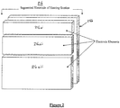
- FIG 2 is a perspective view of a segmented electrode 216a of a heating section 216.
- the segmented electrode 216a comprises three segments 216ai, 216aii and 216aiii. Appropriate electrical switching permits any combination of the three segments to be selectively activated at any given time.
- Electrode 216b is the common return of the electricity supply.
- FIG. 3 is a schematic of a fluid flow path 302 passing three heating sections 316, 317, 318. Each heating section comprises one electrode section segmented into three segments.
- US Patent No. 7,050,706 may be applied to control operation of aspects of the present apparatus and system.
- the segmented electrodes of the present invention may be applied in a fluid heating device comprising a pre-heat reservoir in which fluid is heated to a desired pre-heat temperature and held in a reservoir, with segmented electrodes being used for heating of fluid in an outlet passage through which fluid flows from the reservoir upon demand.
- any suitable number of electrode heating sections may be used in the performance of the present invention.
- the number of heating sections in the passage may be altered in accordance with individual requirements or application specifics for fluid heating. If the number of electrodes is increased to, for example, six pairs, each individual pair may be individually controlled with regards to electrode voltage in the same way as is described in relation to the embodiments herein.
- the number of segments into which a single electrode is segmented may be different to three. For example, segmentation of an electrode into four segments having active areas in a ratio of 1:2:4:8 provides 15 values of effective area which may be selected by the microprocessor control system 141.
- the invention can be applied in applications that include, but are not limited to, domestic hot water systems and domestic near-boiling water dispensers. In relation to both such applications, which are often used for household hot water requirements, the invention can facilitate both energy and water savings. It is further to be appreciated that the provision of segmented electrodes comprising separately active segments permits installation of such a device in locations of widely differing fluid conductivity in which the microprocessor control system 141 can adapt device operation to the particular conductivity encountered without requiring laborious and expensive changes to physical device configuration. Additionally the system principles allow for ease of manufacture, ease of installation at point of use, pleasing aesthetics, and accommodates market established comfort factors. In describing the modes of operation of such applications in more detail, we first consider hot water systems.
- a hot water system in accordance with one embodiment of the invention provides a through flow, instantaneous on-demand hot water system that delivers hot water at pre-settable or fixed temperature to one or more of kitchen, bathroom and laundry in a domestic setting.
- the output temperature can be accurately controlled and kept stable despite adverse water supply conditions that may prevail.
- the electrical power requirements for this type of application usually range between 3.0kW and 33kW and will require either a single or multi-phase alternating current electrical power source.
- the electrical power source requirements can vary depending on the specific nature of the application.
- the system is designed to deliver hot water to the user at flow rates that typically vary between 0.5 litres/min and 151itres/min. Again this depends on the specific application.
- Output water temperatures can be fixed or made settable between 2 degC and 60 degC, which again depend on the application and domestic regulations.
- the temperature increment capability will nominally be 50degC at 10litres/min, but again depends on the application.
- the boiling water dispenser in this embodiment of the invention provides a through flow, instantaneous boiling water dispenser designed to deliver hot water at a fixed output temperature, up to a maximum of 98degC.
- This unit will most often be installed at the point of use in a kitchen-type environment.
- the output temperature is accurately controlled and kept stable despite adverse water supply conditions that may prevail.
- the electrical power requirements for this type of application usually range between 1.2kW and 6kW.
- the flow rate of this dispenser is fixed. This would nominally be fixed at a rate of between 0.5litres/min or 1.2litres/min, but again this depends on the application.
- the power requirement is dependent on the application requirements.
- a two stage boiling water dispenser is provided. If normal single phase power outlets are to be used, the power requirement can be kept to between 1.8kW and 2.5kW which is acceptable for standard domestic power points, and does not require additional or special power circuits.
- This embodiment requires a two stage boiling water dispenser system that includes a water storage component as well as a dynamic through flow component.
- water is first heated to 65degC in a storage system designed to hold nominally 1.8litres to 2.0litres of water. Once heated to 65degC, the boiling water dispenser becomes operable, at which time when turned on the water at 65degC is delivered through the dynamic section to the delivery outlet. This dynamic sector heats the water flowing at 0.8litres/min to 1.2liters/min on demand by an additional 30degC, to an output temperature of 95degC.
Landscapes
- Engineering & Computer Science (AREA)
- Physics & Mathematics (AREA)
- Thermal Sciences (AREA)
- Mechanical Engineering (AREA)
- General Engineering & Computer Science (AREA)
- Combustion & Propulsion (AREA)
- Chemical & Material Sciences (AREA)
- Fluid Mechanics (AREA)
- Power Engineering (AREA)
- Control Of Resistance Heating (AREA)
- Instantaneous Water Boilers, Portable Hot-Water Supply Apparatuses, And Control Of Portable Hot-Water Supply Apparatuses (AREA)
- Water Treatment By Electricity Or Magnetism (AREA)
- Resistance Heating (AREA)
- Footwear And Its Accessory, Manufacturing Method And Apparatuses (AREA)
Claims (15)
- Procédé pour chauffer un fluide, le procédé comprenant le fait :de faire passer le fluide le long d'un trajet d'écoulement (102) d'une entrée à une sortie, le trajet d'écoulement comprenant au moins des première et deuxième sections de chauffage (116, 117, 118) positionnées le long du trajet d'écoulement de sorte que le fluide traversant la première section de chauffage (116) traverse ensuite la deuxième section de chauffage (117, 118), chaque section de chauffage comprenant au moins une paire d'électrodes (116a, 116b; 117a, 117b; 118a, 118b) entre lesquelles un courant électrique traverse le fluide pour chauffer par résistance le fluide au cours de son passage le long du trajet d'écoulement, et où au moins l'une desdites sections de chauffage comprend au moins une électrode segmentée (116ai, 116aii, 106aiii ; 117ai, 117aii, 117aiii ; 118ai, 118aii, 118aiii), l'électrode segmentée comprenant une pluralité de segments électriquement séparables permettant de commander une zone active efficace de l'électrode segmentée en activant sélectivement les segments de sorte que, lors de l'application d'une tension au(x) segment(s) d'électrode activé(s), le courant prélevé dépendra de la zone active efficace ;de mesurer une conductivité de fluide à l'entrée;de déterminer à partir de la conductivité de fluide mesurée une tension et un courant requis à fournir au fluide par la première section de chauffage pour élever la température de fluide d'une première quantité souhaitée ;de déterminer une conductivité de fluide modifiée résultant du fonctionnement de la première section de chauffage ;de déterminer à partir de la conductivité de fluide modifiée une tension et un courant requis à fournir au fluide par la deuxième section de chauffage pour élever la température de fluide d'une deuxième quantité souhaitée ; etd'activer des segments de l'électrode segmentée de manière à effectuer la fourniture du courant et de la tension souhaités par l'électrode segmentée.
- Procédé de la revendication 1, dans lequel des variations de la conductivité de fluide sont reçues en continu en réponse à des mesures de conductivité de fluide entrant.
- Procédé de la revendication 1 ou 2, dans lequel la conductivité de fluide est déterminée par référence au courant prélevé lors de l'application d'une tension aux bornes d'une ou de plusieurs électrode(s) (116a, 116b; 117a, 117b ; 118a, 118b) d'une ou de plusieurs section(s) de chauffage (116, 117, 118).
- Procédé de l'une quelconque des revendications 1 à 3, comprenant en outre le fait d'utiliser la valeur de conductivité mesurée pour sélectionner initialement une combinaison correspondante établie de segments d'électrode (116ai, 116aii, 116aiii; 117ai, 117aii, 117aiii ; 118ai, 118aii, 118aiii) avant de permettre au système de fonctionner afin d'empêcher des variations de conductivité de fluide d'entraîner un dépassement d'une valeur nominale du courant de crête.
- Procédé de l'une quelconque des revendications 1 à 4, comprenant en outre le fait de désactiver les électrodes (116a, 116b ; 117a, 117b ; 118a, 118b) si la conductivité de fluide mesurée tombe en dehors d'une plage prédéterminée de conductivité de fluide acceptable.
- Procédé de l'une quelconque des revendications 1 à 5 comprenant en outre le fait de mesurer un débit de fluide pour aider à déterminer le courant, la tension et l'activation de segment d'électrode appropriés sous des débits de fluide variables, ou de mesurer la température de fluide à la sortie pour permettre une commande à rétroaction du chauffage de fluide.
- Procédé de l'une quelconque des revendications 1 à 6, comprenant en outre le fait de mesurer la température du fluide entre les première et deuxième sections de chauffage et de commander l'alimentation des première et deuxième sections de chauffage conformément aux températures mesurées et à une augmentation souhaitée de température de fluide dans chaque section de chauffage respective.
- Appareil (100) pour chauffer un fluide, l'appareil comprenant :un trajet d'écoulement de fluide (102) d'une entrée à une sortie ;au moins des première et deuxième sections de chauffage (116, 117, 118) positionnées le long du trajet d'écoulement de sorte que le fluide traversant la première section de chauffage (116) traverse ensuite la deuxième section de chauffage (117, 118), chaque section de chauffage comprenant au moins une paire d'électrodes (116a, 116b; 117a, 117b; 118a, 118b) entre lesquelles un courant électrique traverse le fluide pour chauffer par résistance le fluide au cours de son passage le long du trajet d'écoulement, et où au moins l'une desdites sections de chauffage comprend au moins une électrode segmentée, l'électrode segmentée comprenant une pluralité de segments électriquement séparables (116ai, 116aii, 116aiii ; 117ai, 117aii, 117aiii ; 118ai, 118aii, 118aiii) permettant de commander une zone active efficace de l'électrode segmentée en activant sélectivement les segments de sorte que, lors de l'application d'une tension à l'électrode segmentée, le courant prélevé dépendra de la zone active efficace ;un capteur de conductivité (106) pour mesurer une conductivité de fluide à l'entrée ; etune unité de commande (141) pour déterminer à partir de la conductivité de fluide mesurée une tension et un courant requis à fournir au fluide par la première section de chauffage pour élever la température de fluide d'une première quantité souhaitée, pour déterminer une conductivité de fluide modifiée résultant du fonctionnement de la première section de chauffage, pour déterminer à partir de la conductivité de fluide modifiée une tension et un courant requis à fournir au fluide par la deuxième section de chauffage pour élever la température de fluide d'une deuxième quantité souhaitée, et pour activer des segments de l'électrode segmentée de manière à effectuer la fourniture du courant et de la tension souhaités par l'électrode segmentée.
- Appareil de la revendication 8, dans lequel chaque section de chauffage (116, 117, 118) comprend une électrode segmentée (116a, 116b; 117a, 117b; 118a, 118b).
- Appareil de la revendication 8 ou 9, dans lequel chaque électrode segmentée est divisée en segments (116ai, 116aii, 116aiii ; 117ai, 117aii, 117aiii ; 118ai, 118aii, 118aiii) de taille variable, pour permettre à des combinaisons de segments d'être sélectionnées pour obtenir une précision accrue de sélection de zone efficace souhaitée.
- Appareil de la revendication 10, dans lequel l'électrode segmentée (116a, 116b ; 117a, 117b ; 118a, 118b) est divisée en n segments ayant des zones efficaces relatives selon un rapport de 1:2 : ...2(n-1).
- Appareil de l'une quelconque des revendications 8 à 11, dans lequel chaque segment d'électrode (116ai, 116aii, 116aiii ; 117ai, 117aii, 117aiii ; 118ai, 118aii, 118aiii) de l'électrode segmentée (116a, 116b; 117a, 117b; 118a, 118b) s'étend perpendiculairement à une direction d'écoulement de fluide, de manière à soumettre le fluide, sur essentiellement tout le trajet d'écoulement de fluide, à un chauffage résistif.
- Appareil de l'une quelconque des revendications 8 à 12, comprenant en outre un moyen de mesure de débit (104) pour mesurer un débit de fluide pour aider à déterminer le courant, la tension et l'activation de segment d'électrode appropriés sous des débits de fluide variables.
- Appareil de l'une quelconque des revendications 8 à 13, comprenant en outre un moyen de mesure de température de fluide de sortie (136) pour mesurer la température de fluide à la sortie pour permettre une commande à rétroaction du chauffage de fluide.
- Appareil de l'une quelconque des revendications 8 à 14, comprenant en outre un moyen de mesure de température de fluide (138, 139) pour mesurer la température du fluide entre les première et deuxième sections de chauffage (116, 117, 118) et pour commander l'alimentation des première et deuxième sections de chauffage conformément aux températures mesurées et à une augmentation souhaitée de température de fluide dans chaque section de chauffage respective.
Applications Claiming Priority (2)
| Application Number | Priority Date | Filing Date | Title |
|---|---|---|---|
| AU2008900634A AU2008900634A0 (en) | 2008-02-11 | Segmented rapid heating of fluid | |
| PCT/AU2009/000158 WO2009100486A1 (fr) | 2008-02-11 | 2009-02-11 | Chauffage de fluide rapide segmenté |
Publications (3)
| Publication Number | Publication Date |
|---|---|
| EP2247894A1 EP2247894A1 (fr) | 2010-11-10 |
| EP2247894A4 EP2247894A4 (fr) | 2014-12-03 |
| EP2247894B1 true EP2247894B1 (fr) | 2018-06-20 |
Family
ID=40956552
Family Applications (1)
| Application Number | Title | Priority Date | Filing Date |
|---|---|---|---|
| EP09710664.5A Active EP2247894B1 (fr) | 2008-02-11 | 2009-02-11 | Chauffage de fluide rapide segmenté |
Country Status (13)
| Country | Link |
|---|---|
| US (1) | US20100322605A1 (fr) |
| EP (1) | EP2247894B1 (fr) |
| JP (1) | JP2011511919A (fr) |
| CN (1) | CN101952654B (fr) |
| AU (1) | AU2009214821B2 (fr) |
| BR (1) | BRPI0908467B1 (fr) |
| CA (1) | CA2712301C (fr) |
| ES (1) | ES2687417T3 (fr) |
| MX (1) | MX2010008829A (fr) |
| NZ (1) | NZ587587A (fr) |
| RU (1) | RU2484366C2 (fr) |
| WO (1) | WO2009100486A1 (fr) |
| ZA (1) | ZA201005703B (fr) |
Cited By (1)
| Publication number | Priority date | Publication date | Assignee | Title |
|---|---|---|---|---|
| TWI740269B (zh) * | 2018-11-13 | 2021-09-21 | 美商葛萊兒液體處理公司 | 隨需加熱器及溫度控制系統及相關方法 |
Families Citing this family (30)
| Publication number | Priority date | Publication date | Assignee | Title |
|---|---|---|---|---|
| US8861943B2 (en) | 2005-05-04 | 2014-10-14 | Isi Technology, Llc | Liquid heater with temperature control |
| WO2010019833A2 (fr) | 2008-08-13 | 2010-02-18 | Ideas Well Done Llc | Chauffage rapide de liquide |
| WO2010134930A1 (fr) | 2009-05-16 | 2010-11-25 | Ideas Well Done Llc | Contenants de cuisson à vapeur à chauffage ohmique séquentiel d'eau |
| WO2011082452A1 (fr) * | 2010-01-07 | 2011-07-14 | Microheat Technologies Pty Ltd | Générateur de chaleur et procédé de production de chaleur utilisant un fluide électriquement alimenté |
| EP2614315B1 (fr) * | 2010-09-10 | 2016-03-02 | ISI Technology, LLC | Dispositif de chauffage de liquide avec contrôle de la température |
| KR20140016264A (ko) * | 2011-01-07 | 2014-02-07 | 마이크로히트 테크놀로지스 피티와이 엘티디 | 전기유체히터 및 전기로 유체를 가열하는 방법 |
| JP2013141550A (ja) * | 2012-01-12 | 2013-07-22 | Frontier Engineering Co Ltd | 加熱装置 |
| JP6298825B2 (ja) | 2012-12-05 | 2018-03-20 | キム, ノ ウルKIM, No Eul | 電極ユニットを有する電極ボイラ |
| US20150362210A1 (en) * | 2012-12-31 | 2015-12-17 | Steelmax Tech Sa | Electrode boiler featuring variable and controlled output |
| WO2014102555A1 (fr) * | 2012-12-31 | 2014-07-03 | Psomiadis Charalampos | Radiateur autonome à stimulation électrique |
| DK2840404T3 (en) * | 2013-08-20 | 2016-06-27 | Gerdes Ohg | Electric blanket water heater and method for controlling the same |
| JP6173980B2 (ja) * | 2014-07-25 | 2017-08-02 | 株式会社フロンティアエンジニアリング | 加熱方法および加熱装置 |
| PT108702B (pt) * | 2015-07-17 | 2021-02-24 | Bosch Termotecnologia, S.A. | Dispositivo para aparelhos de aquecimento e processo para a operação de um dispositivo para aparelhos de aquecimento |
| KR101840271B1 (ko) | 2016-03-10 | 2018-03-20 | 이극수 | 카본전극을 이용한 다극 순간 전기온수장치 |
| US11493233B2 (en) * | 2016-09-26 | 2022-11-08 | Stone Aerospace, Inc. | Direct high voltage water heater |
| CN106325333B (zh) * | 2016-09-30 | 2018-11-13 | 北京婴萌科技有限公司 | 即热式加热系统 |
| CN106535369B (zh) * | 2016-10-31 | 2019-10-18 | 中国核动力研究设计院 | 一种新型超临界水并联通道分段可调节电加热装置 |
| EP3726927A1 (fr) * | 2016-11-07 | 2020-10-21 | Heatworks Technologies, Inc. | Dispositifs de chauffage ohmique d'un fluide |
| WO2018127577A2 (fr) * | 2017-01-06 | 2018-07-12 | Waturu Holding Aps | Dispositif de chauffage et de traitement d'eau |
| EP3607803B1 (fr) | 2017-04-03 | 2021-02-17 | Instaheat Ag | Système et procédé de chauffage ohmique d'un fluide |
| EA038717B1 (ru) * | 2017-07-21 | 2021-10-08 | Роман Геннадьевич Дашков | Электродный водонагреватель |
| US20190282929A1 (en) * | 2018-03-14 | 2019-09-19 | Redhead Services, L.L.C. | Electric heater treater |
| US10365013B1 (en) | 2018-04-13 | 2019-07-30 | Heatworks Technologies, Inc. | Fluid heater with finite element control |
| CN110067999B (zh) * | 2018-11-28 | 2020-06-30 | 山东交通学院 | 一种分段加热的蒸汽发生器设计方法 |
| CN110368313B (zh) * | 2019-08-13 | 2022-11-08 | 巨翊医疗科技(苏州)有限公司 | 一种输液软管开口式套管加热装置 |
| JP2023503892A (ja) | 2019-11-20 | 2023-02-01 | ヒートワークス・テクノロジーズ,インコーポレイテッド | 複数の動作状態を有するオーミックヒータ |
| GB2596793A (en) | 2020-06-30 | 2022-01-12 | Dyson Technology Ltd | Resistive liquid heater |
| GB2596791B (en) * | 2020-06-30 | 2024-05-29 | Dyson Technology Ltd | Resistive liquid heater |
| GB2596792B (en) | 2020-06-30 | 2022-10-19 | Dyson Technology Ltd | Resistive liquid heater |
| WO2023158814A1 (fr) | 2022-02-17 | 2023-08-24 | OhmIQ, Inc. | Générateur de vapeur |
Family Cites Families (15)
| Publication number | Priority date | Publication date | Assignee | Title |
|---|---|---|---|---|
| US2680802A (en) * | 1952-04-12 | 1954-06-08 | Rainbows Inc | Electrical fluid heater |
| GB745983A (en) * | 1953-04-27 | 1956-03-07 | Indevco Inc | Improvements in or relating to a process and apparatus for heating water by electrical conduction |
| US4029937A (en) * | 1974-10-04 | 1977-06-14 | Russell Robert G | Control system for electrically conductive liquid heating apparatus |
| GB8419987D0 (en) * | 1984-08-01 | 1984-09-12 | Cave N M | Heating devices |
| ZA884526B (en) * | 1987-03-26 | 1989-03-29 | Cedric Israilsohn | Water heating apparatus |
| CA1291785C (fr) * | 1988-07-14 | 1991-11-05 | Andrew J. Read | Dispositif chauffe-eau |
| GB2268671B (en) * | 1992-07-10 | 1996-03-06 | Electricity Ass Tech | Ohmic heating apparatus |
| JPH0688642A (ja) * | 1992-09-08 | 1994-03-29 | Hitachi Home Tec Ltd | 給湯器 |
| CN2228631Y (zh) * | 1995-04-27 | 1996-06-05 | 王基烈 | 全自动快速电热水器 |
| CN2400745Y (zh) * | 1999-12-08 | 2000-10-11 | 袁文征 | 安全即热式电热水器 |
| ES2343169T3 (es) * | 2001-08-13 | 2010-07-26 | Microheat Technologies Pty Ltd. | Sistema y procedimiento de calentamiento rapido de un fluido. |
| RU2256302C1 (ru) * | 2003-12-04 | 2005-07-10 | Терсков Николай Георгиевич | Способ повышения эффективности работы электродного котла и устройство для его реализации |
| US7327951B2 (en) * | 2005-04-21 | 2008-02-05 | Ivanhoe Chaput | Instant water heater with PTC plastic conductive electrodes |
| US7817906B2 (en) * | 2005-05-04 | 2010-10-19 | Isi Technology, Llc | Direct electric resistance liquid heater |
| RU2308823C2 (ru) * | 2005-10-04 | 2007-10-20 | Владимир Григорьевич Бартенев | Способ регулировки мощности электроотопительной системы и устройство для его реализации |
-
2009
- 2009-02-11 CN CN2009801053041A patent/CN101952654B/zh active Active
- 2009-02-11 CA CA2712301A patent/CA2712301C/fr active Active
- 2009-02-11 RU RU2010137848/06A patent/RU2484366C2/ru active
- 2009-02-11 NZ NZ587587A patent/NZ587587A/en unknown
- 2009-02-11 AU AU2009214821A patent/AU2009214821B2/en active Active
- 2009-02-11 EP EP09710664.5A patent/EP2247894B1/fr active Active
- 2009-02-11 MX MX2010008829A patent/MX2010008829A/es active IP Right Grant
- 2009-02-11 US US12/867,138 patent/US20100322605A1/en not_active Abandoned
- 2009-02-11 BR BRPI0908467 patent/BRPI0908467B1/pt active IP Right Grant
- 2009-02-11 WO PCT/AU2009/000158 patent/WO2009100486A1/fr active Application Filing
- 2009-02-11 ES ES09710664.5T patent/ES2687417T3/es active Active
- 2009-02-11 JP JP2010545333A patent/JP2011511919A/ja active Pending
-
2010
- 2010-08-10 ZA ZA2010/05703A patent/ZA201005703B/en unknown
Non-Patent Citations (1)
| Title |
|---|
| None * |
Cited By (1)
| Publication number | Priority date | Publication date | Assignee | Title |
|---|---|---|---|---|
| TWI740269B (zh) * | 2018-11-13 | 2021-09-21 | 美商葛萊兒液體處理公司 | 隨需加熱器及溫度控制系統及相關方法 |
Also Published As
| Publication number | Publication date |
|---|---|
| EP2247894A1 (fr) | 2010-11-10 |
| ES2687417T3 (es) | 2018-10-25 |
| BRPI0908467A2 (pt) | 2016-06-21 |
| CA2712301C (fr) | 2016-08-16 |
| MX2010008829A (es) | 2010-09-07 |
| CN101952654A (zh) | 2011-01-19 |
| NZ587587A (en) | 2012-04-27 |
| ZA201005703B (en) | 2012-01-25 |
| BRPI0908467B1 (pt) | 2019-11-26 |
| JP2011511919A (ja) | 2011-04-14 |
| CA2712301A1 (fr) | 2009-08-20 |
| EP2247894A4 (fr) | 2014-12-03 |
| WO2009100486A1 (fr) | 2009-08-20 |
| US20100322605A1 (en) | 2010-12-23 |
| RU2484366C2 (ru) | 2013-06-10 |
| CN101952654B (zh) | 2013-07-17 |
| AU2009214821B2 (en) | 2012-12-13 |
| RU2010137848A (ru) | 2012-03-20 |
| AU2009214821A1 (en) | 2009-08-20 |
Similar Documents
| Publication | Publication Date | Title |
|---|---|---|
| EP2247894B1 (fr) | Chauffage de fluide rapide segmenté | |
| US7050706B2 (en) | System and method for rapid heating of fluid | |
| AU2008232295B2 (en) | System and method for improved heating of fluid | |
| AU2002322166A1 (en) | System and method for rapid heating of fluid | |
| BRPI0909367B1 (pt) | calçado e método de fabricação do mesmo | |
| RU2584514C2 (ru) | Энергосберегающая кофемашина | |
| WO2002053988A2 (fr) | Procede et systeme pour detecter un etat de marche a vide dans un chauffe-eau | |
| CA2366279A1 (fr) | Chauffe-eau comprenant des elements chauffants doubles cote-a-cote | |
| KR20110055377A (ko) | 히터에 인가되는 펄스의 개수를 제어하는 온수공급장치 및 온수공급방법 | |
| CA2978997A1 (fr) | Chauffe-eau electrique a double element sans reservoir | |
| AU2007234597A1 (en) | System and method for rapid heating of fluid | |
| Gouws et al. | Efficiency and cost analysis of a designed in-line water heating system compared to a conventional water heating system in South Africa | |
| GB2589112A (en) | Water heater for use in a plumbing system |
Legal Events
| Date | Code | Title | Description |
|---|---|---|---|
| PUAI | Public reference made under article 153(3) epc to a published international application that has entered the european phase |
Free format text: ORIGINAL CODE: 0009012 |
|
| 17P | Request for examination filed |
Effective date: 20100723 |
|
| AK | Designated contracting states |
Kind code of ref document: A1 Designated state(s): AT BE BG CH CY CZ DE DK EE ES FI FR GB GR HR HU IE IS IT LI LT LU LV MC MK MT NL NO PL PT RO SE SI SK TR |
|
| AX | Request for extension of the european patent |
Extension state: AL BA RS |
|
| REG | Reference to a national code |
Ref country code: HK Ref legal event code: DE Ref document number: 1145355 Country of ref document: HK |
|
| DAX | Request for extension of the european patent (deleted) | ||
| A4 | Supplementary search report drawn up and despatched |
Effective date: 20141103 |
|
| RIC1 | Information provided on ipc code assigned before grant |
Ipc: H05B 3/03 20060101ALI20141028BHEP Ipc: F22B 1/30 20060101AFI20141028BHEP Ipc: F24D 13/02 20060101ALI20141028BHEP Ipc: F24H 1/10 20060101ALI20141028BHEP |
|
| GRAP | Despatch of communication of intention to grant a patent |
Free format text: ORIGINAL CODE: EPIDOSNIGR1 |
|
| STAA | Information on the status of an ep patent application or granted ep patent |
Free format text: STATUS: GRANT OF PATENT IS INTENDED |
|
| INTG | Intention to grant announced |
Effective date: 20180108 |
|
| GRAS | Grant fee paid |
Free format text: ORIGINAL CODE: EPIDOSNIGR3 |
|
| GRAA | (expected) grant |
Free format text: ORIGINAL CODE: 0009210 |
|
| STAA | Information on the status of an ep patent application or granted ep patent |
Free format text: STATUS: THE PATENT HAS BEEN GRANTED |
|
| AK | Designated contracting states |
Kind code of ref document: B1 Designated state(s): AT BE BG CH CY CZ DE DK EE ES FI FR GB GR HR HU IE IS IT LI LT LU LV MC MK MT NL NO PL PT RO SE SI SK TR |
|
| REG | Reference to a national code |
Ref country code: GB Ref legal event code: FG4D |
|
| REG | Reference to a national code |
Ref country code: IE Ref legal event code: FG4D |
|
| REG | Reference to a national code |
Ref country code: DE Ref legal event code: R096 Ref document number: 602009052860 Country of ref document: DE |
|
| REG | Reference to a national code |
Ref country code: AT Ref legal event code: REF Ref document number: 1010867 Country of ref document: AT Kind code of ref document: T Effective date: 20180715 |
|
| REG | Reference to a national code |
Ref country code: NL Ref legal event code: MP Effective date: 20180620 |
|
| REG | Reference to a national code |
Ref country code: ES Ref legal event code: FG2A Ref document number: 2687417 Country of ref document: ES Kind code of ref document: T3 Effective date: 20181025 |
|
| PG25 | Lapsed in a contracting state [announced via postgrant information from national office to epo] |
Ref country code: LT Free format text: LAPSE BECAUSE OF FAILURE TO SUBMIT A TRANSLATION OF THE DESCRIPTION OR TO PAY THE FEE WITHIN THE PRESCRIBED TIME-LIMIT Effective date: 20180620 Ref country code: SE Free format text: LAPSE BECAUSE OF FAILURE TO SUBMIT A TRANSLATION OF THE DESCRIPTION OR TO PAY THE FEE WITHIN THE PRESCRIBED TIME-LIMIT Effective date: 20180620 Ref country code: BG Free format text: LAPSE BECAUSE OF FAILURE TO SUBMIT A TRANSLATION OF THE DESCRIPTION OR TO PAY THE FEE WITHIN THE PRESCRIBED TIME-LIMIT Effective date: 20180920 Ref country code: NO Free format text: LAPSE BECAUSE OF FAILURE TO SUBMIT A TRANSLATION OF THE DESCRIPTION OR TO PAY THE FEE WITHIN THE PRESCRIBED TIME-LIMIT Effective date: 20180920 Ref country code: FI Free format text: LAPSE BECAUSE OF FAILURE TO SUBMIT A TRANSLATION OF THE DESCRIPTION OR TO PAY THE FEE WITHIN THE PRESCRIBED TIME-LIMIT Effective date: 20180620 |
|
| REG | Reference to a national code |
Ref country code: LT Ref legal event code: MG4D |
|
| PG25 | Lapsed in a contracting state [announced via postgrant information from national office to epo] |
Ref country code: HR Free format text: LAPSE BECAUSE OF FAILURE TO SUBMIT A TRANSLATION OF THE DESCRIPTION OR TO PAY THE FEE WITHIN THE PRESCRIBED TIME-LIMIT Effective date: 20180620 Ref country code: GR Free format text: LAPSE BECAUSE OF FAILURE TO SUBMIT A TRANSLATION OF THE DESCRIPTION OR TO PAY THE FEE WITHIN THE PRESCRIBED TIME-LIMIT Effective date: 20180921 Ref country code: LV Free format text: LAPSE BECAUSE OF FAILURE TO SUBMIT A TRANSLATION OF THE DESCRIPTION OR TO PAY THE FEE WITHIN THE PRESCRIBED TIME-LIMIT Effective date: 20180620 |
|
| REG | Reference to a national code |
Ref country code: AT Ref legal event code: MK05 Ref document number: 1010867 Country of ref document: AT Kind code of ref document: T Effective date: 20180620 |
|
| PG25 | Lapsed in a contracting state [announced via postgrant information from national office to epo] |
Ref country code: NL Free format text: LAPSE BECAUSE OF FAILURE TO SUBMIT A TRANSLATION OF THE DESCRIPTION OR TO PAY THE FEE WITHIN THE PRESCRIBED TIME-LIMIT Effective date: 20180620 |
|
| PG25 | Lapsed in a contracting state [announced via postgrant information from national office to epo] |
Ref country code: AT Free format text: LAPSE BECAUSE OF FAILURE TO SUBMIT A TRANSLATION OF THE DESCRIPTION OR TO PAY THE FEE WITHIN THE PRESCRIBED TIME-LIMIT Effective date: 20180620 Ref country code: EE Free format text: LAPSE BECAUSE OF FAILURE TO SUBMIT A TRANSLATION OF THE DESCRIPTION OR TO PAY THE FEE WITHIN THE PRESCRIBED TIME-LIMIT Effective date: 20180620 Ref country code: IS Free format text: LAPSE BECAUSE OF FAILURE TO SUBMIT A TRANSLATION OF THE DESCRIPTION OR TO PAY THE FEE WITHIN THE PRESCRIBED TIME-LIMIT Effective date: 20181020 Ref country code: RO Free format text: LAPSE BECAUSE OF FAILURE TO SUBMIT A TRANSLATION OF THE DESCRIPTION OR TO PAY THE FEE WITHIN THE PRESCRIBED TIME-LIMIT Effective date: 20180620 Ref country code: SK Free format text: LAPSE BECAUSE OF FAILURE TO SUBMIT A TRANSLATION OF THE DESCRIPTION OR TO PAY THE FEE WITHIN THE PRESCRIBED TIME-LIMIT Effective date: 20180620 Ref country code: CZ Free format text: LAPSE BECAUSE OF FAILURE TO SUBMIT A TRANSLATION OF THE DESCRIPTION OR TO PAY THE FEE WITHIN THE PRESCRIBED TIME-LIMIT Effective date: 20180620 Ref country code: PL Free format text: LAPSE BECAUSE OF FAILURE TO SUBMIT A TRANSLATION OF THE DESCRIPTION OR TO PAY THE FEE WITHIN THE PRESCRIBED TIME-LIMIT Effective date: 20180620 |
|
| REG | Reference to a national code |
Ref country code: DE Ref legal event code: R097 Ref document number: 602009052860 Country of ref document: DE |
|
| PLBE | No opposition filed within time limit |
Free format text: ORIGINAL CODE: 0009261 |
|
| STAA | Information on the status of an ep patent application or granted ep patent |
Free format text: STATUS: NO OPPOSITION FILED WITHIN TIME LIMIT |
|
| 26N | No opposition filed |
Effective date: 20190321 |
|
| PG25 | Lapsed in a contracting state [announced via postgrant information from national office to epo] |
Ref country code: DK Free format text: LAPSE BECAUSE OF FAILURE TO SUBMIT A TRANSLATION OF THE DESCRIPTION OR TO PAY THE FEE WITHIN THE PRESCRIBED TIME-LIMIT Effective date: 20180620 |
|
| PG25 | Lapsed in a contracting state [announced via postgrant information from national office to epo] |
Ref country code: SI Free format text: LAPSE BECAUSE OF FAILURE TO SUBMIT A TRANSLATION OF THE DESCRIPTION OR TO PAY THE FEE WITHIN THE PRESCRIBED TIME-LIMIT Effective date: 20180620 |
|
| REG | Reference to a national code |
Ref country code: CH Ref legal event code: PL |
|
| PG25 | Lapsed in a contracting state [announced via postgrant information from national office to epo] |
Ref country code: MC Free format text: LAPSE BECAUSE OF FAILURE TO SUBMIT A TRANSLATION OF THE DESCRIPTION OR TO PAY THE FEE WITHIN THE PRESCRIBED TIME-LIMIT Effective date: 20180620 Ref country code: LU Free format text: LAPSE BECAUSE OF NON-PAYMENT OF DUE FEES Effective date: 20190211 |
|
| REG | Reference to a national code |
Ref country code: BE Ref legal event code: MM Effective date: 20190228 |
|
| REG | Reference to a national code |
Ref country code: IE Ref legal event code: MM4A |
|
| PG25 | Lapsed in a contracting state [announced via postgrant information from national office to epo] |
Ref country code: LI Free format text: LAPSE BECAUSE OF NON-PAYMENT OF DUE FEES Effective date: 20190228 Ref country code: CH Free format text: LAPSE BECAUSE OF NON-PAYMENT OF DUE FEES Effective date: 20190228 |
|
| PG25 | Lapsed in a contracting state [announced via postgrant information from national office to epo] |
Ref country code: IE Free format text: LAPSE BECAUSE OF NON-PAYMENT OF DUE FEES Effective date: 20190211 |
|
| PG25 | Lapsed in a contracting state [announced via postgrant information from national office to epo] |
Ref country code: BE Free format text: LAPSE BECAUSE OF NON-PAYMENT OF DUE FEES Effective date: 20190228 |
|
| PG25 | Lapsed in a contracting state [announced via postgrant information from national office to epo] |
Ref country code: TR Free format text: LAPSE BECAUSE OF FAILURE TO SUBMIT A TRANSLATION OF THE DESCRIPTION OR TO PAY THE FEE WITHIN THE PRESCRIBED TIME-LIMIT Effective date: 20180620 |
|
| PG25 | Lapsed in a contracting state [announced via postgrant information from national office to epo] |
Ref country code: MT Free format text: LAPSE BECAUSE OF NON-PAYMENT OF DUE FEES Effective date: 20190211 Ref country code: PT Free format text: LAPSE BECAUSE OF FAILURE TO SUBMIT A TRANSLATION OF THE DESCRIPTION OR TO PAY THE FEE WITHIN THE PRESCRIBED TIME-LIMIT Effective date: 20181022 |
|
| PG25 | Lapsed in a contracting state [announced via postgrant information from national office to epo] |
Ref country code: CY Free format text: LAPSE BECAUSE OF FAILURE TO SUBMIT A TRANSLATION OF THE DESCRIPTION OR TO PAY THE FEE WITHIN THE PRESCRIBED TIME-LIMIT Effective date: 20180620 |
|
| PG25 | Lapsed in a contracting state [announced via postgrant information from national office to epo] |
Ref country code: HU Free format text: LAPSE BECAUSE OF FAILURE TO SUBMIT A TRANSLATION OF THE DESCRIPTION OR TO PAY THE FEE WITHIN THE PRESCRIBED TIME-LIMIT; INVALID AB INITIO Effective date: 20090211 |
|
| PG25 | Lapsed in a contracting state [announced via postgrant information from national office to epo] |
Ref country code: MK Free format text: LAPSE BECAUSE OF FAILURE TO SUBMIT A TRANSLATION OF THE DESCRIPTION OR TO PAY THE FEE WITHIN THE PRESCRIBED TIME-LIMIT Effective date: 20180620 |
|
| PGFP | Annual fee paid to national office [announced via postgrant information from national office to epo] |
Ref country code: FR Payment date: 20230220 Year of fee payment: 15 |
|
| PGFP | Annual fee paid to national office [announced via postgrant information from national office to epo] |
Ref country code: IT Payment date: 20230223 Year of fee payment: 15 |
|
| P01 | Opt-out of the competence of the unified patent court (upc) registered |
Effective date: 20230522 |
|
| PGFP | Annual fee paid to national office [announced via postgrant information from national office to epo] |
Ref country code: ES Payment date: 20240325 Year of fee payment: 16 |
|
| PGFP | Annual fee paid to national office [announced via postgrant information from national office to epo] |
Ref country code: DE Payment date: 20240219 Year of fee payment: 16 Ref country code: GB Payment date: 20240219 Year of fee payment: 16 |