EP2247840B1 - Speed controller for piston engine - Google Patents
Speed controller for piston engine Download PDFInfo
- Publication number
- EP2247840B1 EP2247840B1 EP09718195.2A EP09718195A EP2247840B1 EP 2247840 B1 EP2247840 B1 EP 2247840B1 EP 09718195 A EP09718195 A EP 09718195A EP 2247840 B1 EP2247840 B1 EP 2247840B1
- Authority
- EP
- European Patent Office
- Prior art keywords
- controller
- speed
- interface
- control
- monitoring section
- Prior art date
- Legal status (The legal status is an assumption and is not a legal conclusion. Google has not performed a legal analysis and makes no representation as to the accuracy of the status listed.)
- Active
Links
Images
Classifications
-
- G—PHYSICS
- G05—CONTROLLING; REGULATING
- G05B—CONTROL OR REGULATING SYSTEMS IN GENERAL; FUNCTIONAL ELEMENTS OF SUCH SYSTEMS; MONITORING OR TESTING ARRANGEMENTS FOR SUCH SYSTEMS OR ELEMENTS
- G05B13/00—Adaptive control systems, i.e. systems automatically adjusting themselves to have a performance which is optimum according to some preassigned criterion
- G05B13/02—Adaptive control systems, i.e. systems automatically adjusting themselves to have a performance which is optimum according to some preassigned criterion electric
- G05B13/04—Adaptive control systems, i.e. systems automatically adjusting themselves to have a performance which is optimum according to some preassigned criterion electric involving the use of models or simulators
- G05B13/041—Adaptive control systems, i.e. systems automatically adjusting themselves to have a performance which is optimum according to some preassigned criterion electric involving the use of models or simulators in which a variable is automatically adjusted to optimise the performance
-
- F—MECHANICAL ENGINEERING; LIGHTING; HEATING; WEAPONS; BLASTING
- F02—COMBUSTION ENGINES; HOT-GAS OR COMBUSTION-PRODUCT ENGINE PLANTS
- F02D—CONTROLLING COMBUSTION ENGINES
- F02D31/00—Use of speed-sensing governors to control combustion engines, not otherwise provided for
- F02D31/001—Electric control of rotation speed
-
- F—MECHANICAL ENGINEERING; LIGHTING; HEATING; WEAPONS; BLASTING
- F02—COMBUSTION ENGINES; HOT-GAS OR COMBUSTION-PRODUCT ENGINE PLANTS
- F02D—CONTROLLING COMBUSTION ENGINES
- F02D41/00—Electrical control of supply of combustible mixture or its constituents
- F02D41/02—Circuit arrangements for generating control signals
- F02D41/14—Introducing closed-loop corrections
- F02D41/1497—With detection of the mechanical response of the engine
- F02D41/1498—With detection of the mechanical response of the engine measuring engine roughness
-
- F—MECHANICAL ENGINEERING; LIGHTING; HEATING; WEAPONS; BLASTING
- F02—COMBUSTION ENGINES; HOT-GAS OR COMBUSTION-PRODUCT ENGINE PLANTS
- F02D—CONTROLLING COMBUSTION ENGINES
- F02D41/00—Electrical control of supply of combustible mixture or its constituents
- F02D41/24—Electrical control of supply of combustible mixture or its constituents characterised by the use of digital means
- F02D41/26—Electrical control of supply of combustible mixture or its constituents characterised by the use of digital means using computer, e.g. microprocessor
- F02D41/28—Interface circuits
-
- G—PHYSICS
- G05—CONTROLLING; REGULATING
- G05B—CONTROL OR REGULATING SYSTEMS IN GENERAL; FUNCTIONAL ELEMENTS OF SUCH SYSTEMS; MONITORING OR TESTING ARRANGEMENTS FOR SUCH SYSTEMS OR ELEMENTS
- G05B13/00—Adaptive control systems, i.e. systems automatically adjusting themselves to have a performance which is optimum according to some preassigned criterion
- G05B13/02—Adaptive control systems, i.e. systems automatically adjusting themselves to have a performance which is optimum according to some preassigned criterion electric
- G05B13/0205—Adaptive control systems, i.e. systems automatically adjusting themselves to have a performance which is optimum according to some preassigned criterion electric not using a model or a simulator of the controlled system
- G05B13/021—Adaptive control systems, i.e. systems automatically adjusting themselves to have a performance which is optimum according to some preassigned criterion electric not using a model or a simulator of the controlled system in which a variable is automatically adjusted to optimise the performance
-
- G—PHYSICS
- G05—CONTROLLING; REGULATING
- G05B—CONTROL OR REGULATING SYSTEMS IN GENERAL; FUNCTIONAL ELEMENTS OF SUCH SYSTEMS; MONITORING OR TESTING ARRANGEMENTS FOR SUCH SYSTEMS OR ELEMENTS
- G05B13/00—Adaptive control systems, i.e. systems automatically adjusting themselves to have a performance which is optimum according to some preassigned criterion
- G05B13/02—Adaptive control systems, i.e. systems automatically adjusting themselves to have a performance which is optimum according to some preassigned criterion electric
- G05B13/0205—Adaptive control systems, i.e. systems automatically adjusting themselves to have a performance which is optimum according to some preassigned criterion electric not using a model or a simulator of the controlled system
- G05B13/024—Adaptive control systems, i.e. systems automatically adjusting themselves to have a performance which is optimum according to some preassigned criterion electric not using a model or a simulator of the controlled system in which a parameter or coefficient is automatically adjusted to optimise the performance
-
- G—PHYSICS
- G05—CONTROLLING; REGULATING
- G05B—CONTROL OR REGULATING SYSTEMS IN GENERAL; FUNCTIONAL ELEMENTS OF SUCH SYSTEMS; MONITORING OR TESTING ARRANGEMENTS FOR SUCH SYSTEMS OR ELEMENTS
- G05B13/00—Adaptive control systems, i.e. systems automatically adjusting themselves to have a performance which is optimum according to some preassigned criterion
- G05B13/02—Adaptive control systems, i.e. systems automatically adjusting themselves to have a performance which is optimum according to some preassigned criterion electric
- G05B13/04—Adaptive control systems, i.e. systems automatically adjusting themselves to have a performance which is optimum according to some preassigned criterion electric involving the use of models or simulators
- G05B13/042—Adaptive control systems, i.e. systems automatically adjusting themselves to have a performance which is optimum according to some preassigned criterion electric involving the use of models or simulators in which a parameter or coefficient is automatically adjusted to optimise the performance
-
- F—MECHANICAL ENGINEERING; LIGHTING; HEATING; WEAPONS; BLASTING
- F02—COMBUSTION ENGINES; HOT-GAS OR COMBUSTION-PRODUCT ENGINE PLANTS
- F02D—CONTROLLING COMBUSTION ENGINES
- F02D41/00—Electrical control of supply of combustible mixture or its constituents
- F02D41/02—Circuit arrangements for generating control signals
- F02D41/14—Introducing closed-loop corrections
- F02D41/1401—Introducing closed-loop corrections characterised by the control or regulation method
- F02D2041/1409—Introducing closed-loop corrections characterised by the control or regulation method using at least a proportional, integral or derivative controller
-
- F—MECHANICAL ENGINEERING; LIGHTING; HEATING; WEAPONS; BLASTING
- F02—COMBUSTION ENGINES; HOT-GAS OR COMBUSTION-PRODUCT ENGINE PLANTS
- F02D—CONTROLLING COMBUSTION ENGINES
- F02D41/00—Electrical control of supply of combustible mixture or its constituents
- F02D41/02—Circuit arrangements for generating control signals
- F02D41/14—Introducing closed-loop corrections
- F02D41/1401—Introducing closed-loop corrections characterised by the control or regulation method
- F02D2041/1413—Controller structures or design
- F02D2041/1422—Variable gain or coefficients
-
- F—MECHANICAL ENGINEERING; LIGHTING; HEATING; WEAPONS; BLASTING
- F02—COMBUSTION ENGINES; HOT-GAS OR COMBUSTION-PRODUCT ENGINE PLANTS
- F02D—CONTROLLING COMBUSTION ENGINES
- F02D41/00—Electrical control of supply of combustible mixture or its constituents
- F02D41/02—Circuit arrangements for generating control signals
- F02D41/14—Introducing closed-loop corrections
- F02D41/1401—Introducing closed-loop corrections characterised by the control or regulation method
- F02D2041/1413—Controller structures or design
- F02D2041/1432—Controller structures or design the system including a filter, e.g. a low pass or high pass filter
-
- F—MECHANICAL ENGINEERING; LIGHTING; HEATING; WEAPONS; BLASTING
- F02—COMBUSTION ENGINES; HOT-GAS OR COMBUSTION-PRODUCT ENGINE PLANTS
- F02D—CONTROLLING COMBUSTION ENGINES
- F02D41/00—Electrical control of supply of combustible mixture or its constituents
- F02D41/22—Safety or indicating devices for abnormal conditions
- F02D2041/228—Warning displays
-
- F—MECHANICAL ENGINEERING; LIGHTING; HEATING; WEAPONS; BLASTING
- F02—COMBUSTION ENGINES; HOT-GAS OR COMBUSTION-PRODUCT ENGINE PLANTS
- F02D—CONTROLLING COMBUSTION ENGINES
- F02D41/00—Electrical control of supply of combustible mixture or its constituents
- F02D41/02—Circuit arrangements for generating control signals
- F02D41/14—Introducing closed-loop corrections
- F02D41/1401—Introducing closed-loop corrections characterised by the control or regulation method
- F02D41/1402—Adaptive control
Definitions
- the invention relates to a speed controller for a piston engine.
- the invention particularly relates to a speed controller for a ship piston engine.
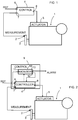
- Figure 1 illustrates an example of a prior art speed controller 4 for a piston engine 1.
- the speed of the piston engine's main shaft is measured using sensor 2 on the flywheel 3, for example.
- the measurement data from the sensor is forwarded to the speed controller 4, which compares the measured speed with the reference speed.
- the speed controller issues control signals to an actuator or actuators 5 in the engine in order to adjust the engine speed (more precisely the rotational speed of the engine's main shaft) to a desired value known as the reference speed value.
- the speed controller comprises a first interface 6 for receiving reference data (the reference signal), a second interface 7 for receiving measurement data (the measurement signal), and a third interface 8 for transmitting a control signal to the actuator.
- the actuator is usually a valve regulating the quantity of fuel supplied into the engine, or the control signal may control the cylinder-specific fuel injectors.
- US 20060011167 discloses a known PI controller wherein two feedback loops are used to provide two difference signals into the controller.
- a speed controller is required to keep the engine speed at the desired value and within the desired range. If there is no speed controller, the engine speed may deviate from the intended operating range, and this may lead to engine damage.
- a speed controller normally uses a PID algorithm. The controller is usually tuned so that the engine speed would deviate as little as possible with changing engine load, and that the engine speed would not oscillate at a stable speed. If the controller is tuned to respond rapidly to changes in engine load, the engine speed will easily oscillate at even load - that is, when operating the engine at a stable speed. On the other hand, if the controller is tuned to completely or almost completely eliminate oscillation of the engine speed at a stable speed, the controller will be slow to respond to changes in engine load.
- the tuning would only operate appropriately under the conditions prevalent at the time of tuning.
- the conditions prevalent in an engine change for many reasons, such as wear and tear of the engine's mechanical components, variations in engine load, variations in the quality of fuel, variations in environmental conditions, changes in the temperature of a flexible coupling linked to the engine shaft, etc.
- engine control becomes either more oscillatory or slower.
- a PID controller (or other type of controller) must be tuned in practice without more detailed informational or theoretical support.
- an oscillating engine constitutes a serious problem because oscillation speeds up wear and tear on the engine.
- the engine is usually linked to the load (ship's generator, ship's propeller) through a flexible coupling.
- the coupling attenuates the natural oscillation of the engine, caused by crankshaft rotation.
- Crankshaft oscillation is due to the nonsimultaneous power strokes of the pistons connected to the crankshaft, which provide energy from the consumption of fuel.
- the flexible coupling is dimensioned to bear the normal oscillation and power of the engine.
- the oscillation caused by the operation of the engine speed controller is substantially larger in magnitude compared to the engine's natural oscillation.
- the situation is particularly severe when the frequencies of the engine's natural oscillations and the oscillations caused by control occur at the resonant frequency of the engine system (engine, coupling and system main shaft with load).
- the resonant system may damage system components.
- the flexible coupling is a component that will be likely to break.
- Oscillation caused by control thus imposes additional stress on the flexible coupling. Additional stress increases the temperature of the internals of the coupling, which reduces its service life and, at worst, may cause damage to the coupling. Breakdown of the flexible coupling during operation may correspondingly cause damage to the engine and/or load.
- the objective of the invention is to reduce oscillations in the rotational speed of an engine caused by the speed controller.
- the objective will be achieved through a speed controller for controlling the speed of a piston engine according to claim 1.
- the piston engine speed controller of the present invention can analyse the oscillations it is causing and take the necessary action on this basis.
- FIG. 2 illustrates an example of an embodiment 9 of the invention.
- the speed controller 9 according to the invention comprises a speed controller section 4 (controller) and a monitoring section 10.
- the controller 4 is a normal speed controller of any known controller type, such as PID controller etc.
- the controller 4 has a first interface 6 for receiving reference data, a second interface 7 for receiving measurement data of the engine speed (more precisely the rotational speed), and a third interface 8 for transmitting a control signal to control the speed of the piston engine.
- the controller section 4 is arranged to generate said control signal in response to the received measurement data and reference data.
- the purpose of the monitoring section 10 is to monitor the responses in engine speed caused by the actions of the speed controller 4.
- the monitoring section comprises a fourth interface 11 for receiving measurement data of the engine speed, a fifth interface 12 for transmitting a control change signal to the controller 4, and a sixth interface 13 for transmitting a message regarding the response in engine speed caused by controller operation.
- the monitoring section is thus arranged to generate a control change signal to control the controller 4 through the fifth interface 12 as necessary, and to generate a message regarding the response caused by controller operation for transmission through the sixth interface 13 as necessary.
- the message to be transmitted is an alarm of a certain level or a message of a lower level.
- the message shall be received, for example, at a separate monitoring centre where a supervisor can react to the message as considered appropriate.
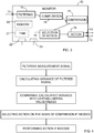
- FIG. 3 illustrates the monitoring section 10 in more detail.
- the monitoring section 10 comprises a filter 15 for filtering the highest frequencies and the direct current component from the measurement data signal, a computation element 16 for calculating the values corresponding to a certain quantity or quantities from the filtered measurement data signal, a comparison element 17 for comparing the calculated values with a certain limit or limits, a selection element 18 for selecting the appropriate action on the basis of the comparison, and action elements 19 for carrying out the selected action(s).
- the filter section 15 can be, for example, an analogue low-pass filter or a digital filter such as a FIR filter.
- the implementation of the filter section depends on the intended way of constructing the monitoring section - with analogue components or digital components.
- the computation element 16 is arranged to calculate the values of a quantity or quantities.
- the computation element (16) calculates the variance value.
- Variance represents deviation of the signal in relation to its expected value.
- Formula (1) means that the average of the squares of the differences constitutes the expected value of deviation, also known as the variance. There are naturally also other ways of determining variance.
- the engine's natural oscillations cause variance in the engine speed compared to a completely non-oscillating speed. Uneven wear on the engine's cylinder also increases variance in engine speed. Thus the variance value is dependent on the quantity of oscillation and therefore the state of the engine. Conventional variance values in different states of the engine can be determined in advance.
- the operation of the controller 4 causes high variance values for engine speed.
- a comparison of the variance values calculated by the monitoring section 10 with predetermined conventional variance values makes it possible to conclude whether controller operation has caused oscillations in engine speed to a harmful extent.
- the comparison element 17 compares the calculated variance with predetermined values. A comparison can be made by comparing the values with each other or by calculating the difference of the values. On the basis of the comparison, the selection element chooses the way of action. If the value stored in advance is less than the calculated value, the generation of a message and/or control signal is chosen. There may be several values stored in advance, and the action chosen may depend on how many stored values are exceeded by the calculated value. The stored values can thus serve as limits, and certain actions will be taken when the limits are exceeded. The limits can be set so that the monitoring section 10 will not be too sensitive to control the operation of the controller section 4. If the difference between the calculated value and stored value is used for comparison, the magnitude of the difference is the criterion for choosing the way of action.
- Messages and control signals can be generated.
- Messages and control signals can be used separately or jointly to generate a way of action.
- the action elements 19 are arranged to generate the chosen control change signal to control the speed controller 4 and to generate a message regarding the response caused by controller operation.
- the action elements can be a single entity or one consisting of several parts.
- the monitoring section also comprises a timing arrangement 21 arranged to provide time information (for time stamps) to other parts of the controller, and a seventh interface 22 to receive information of each control action executed by the controller 4.
- the computation element 16 is arranged to attach a time stamp to the calculated value, and an appropriate part of the monitoring section 10, such as the interface 22, is arranged to attach a time stamp to the action data of the controller 4.
- the comparison element 17 and the selection element 18 are arranged to utilise said time stamps to select action. If the time stamp of calculated variance is close to the time stamp of control action by the controller 4, accounting for the time constants of the engine and controller, it can be concluded more precisely that control action has caused oscillation in engine speed.
- the presented embodiments also contain section-specific memory capacity or a separate memory 20 that stores necessary information (values stored in advance, information on control actions executed by the controller 4, values of calculated quantities and time stamps attached to data).
- the controller section 4 must also have an arrangement for sending information on control action to the monitoring section 10.
- the arrangement can be a separate interface through which said data is forwarded to the seventh interface in the monitoring section, or the control change signal can also be forwarded to the monitoring section.
- the dotted line in Figure 2 illustrates this arrangement.
- FIGS 2 and 3 illustrate embodiments of the invention in very simplified form. It shall be kept in mind that practical embodiments can be implemented in several different ways and may contain parts and functions not illustrated in Figures 2 and 3 .
- the monitoring section can be implemented so that at least the computation element 16, the comparison element 17 and the selection element 18 are software entities intended to be executed in the monitoring section's processing unit.
- the software entity may be a separate program or a subpart of a larger program.
- the monitoring section 10 in its entirety may also be a circuit board, such as a circuit board comprising an ASIC (Application Specific Integrated Circuit).
- ASIC Application Specific Integrated Circuit
- the monitoring section may also comprise an eighth interface 23 through which the monitoring section can be reconfigured as necessary.
- the speed controller according to the invention is able to analyse the dynamic behaviour of the controller and engine in a simple and reliable way and to distinguish between engine speed oscillations caused by controller operation and the natural oscillations of the engine. No complex and detailed modelling of the engine needs to be known.
- the invention is well-suited to be used as a speed controller for ship engines.
- the invention can be implemented as a PID controller or other type of controller.
Landscapes
- Engineering & Computer Science (AREA)
- Software Systems (AREA)
- General Physics & Mathematics (AREA)
- Automation & Control Theory (AREA)
- Medical Informatics (AREA)
- Physics & Mathematics (AREA)
- Computer Vision & Pattern Recognition (AREA)
- Health & Medical Sciences (AREA)
- Artificial Intelligence (AREA)
- Evolutionary Computation (AREA)
- Combustion & Propulsion (AREA)
- Chemical & Material Sciences (AREA)
- General Engineering & Computer Science (AREA)
- Mechanical Engineering (AREA)
- Microelectronics & Electronic Packaging (AREA)
- Computer Hardware Design (AREA)
- Combined Controls Of Internal Combustion Engines (AREA)
- Control Of Electric Motors In General (AREA)
Description
- The invention relates to a speed controller for a piston engine. The invention particularly relates to a speed controller for a ship piston engine.
-
Figure 1 illustrates an example of a priorart speed controller 4 for apiston engine 1. The speed of the piston engine's main shaft, more precisely the rotational speed, is measured usingsensor 2 on theflywheel 3, for example. The measurement data from the sensor is forwarded to thespeed controller 4, which compares the measured speed with the reference speed. On the basis of this comparison, the speed controller issues control signals to an actuator oractuators 5 in the engine in order to adjust the engine speed (more precisely the rotational speed of the engine's main shaft) to a desired value known as the reference speed value. The speed controller comprises afirst interface 6 for receiving reference data (the reference signal), asecond interface 7 for receiving measurement data (the measurement signal), and athird interface 8 for transmitting a control signal to the actuator. The actuator is usually a valve regulating the quantity of fuel supplied into the engine, or the control signal may control the cylinder-specific fuel injectors. -
US 20060011167 discloses a known PI controller wherein two feedback loops are used to provide two difference signals into the controller. - A speed controller is required to keep the engine speed at the desired value and within the desired range. If there is no speed controller, the engine speed may deviate from the intended operating range, and this may lead to engine damage. A speed controller normally uses a PID algorithm. The controller is usually tuned so that the engine speed would deviate as little as possible with changing engine load, and that the engine speed would not oscillate at a stable speed. If the controller is tuned to respond rapidly to changes in engine load, the engine speed will easily oscillate at even load - that is, when operating the engine at a stable speed. On the other hand, if the controller is tuned to completely or almost completely eliminate oscillation of the engine speed at a stable speed, the controller will be slow to respond to changes in engine load.
- Even if these two criteria could be sufficiently accounted for in the tuning of the controller, the tuning would only operate appropriately under the conditions prevalent at the time of tuning. In practice, the conditions prevalent in an engine change for many reasons, such as wear and tear of the engine's mechanical components, variations in engine load, variations in the quality of fuel, variations in environmental conditions, changes in the temperature of a flexible coupling linked to the engine shaft, etc. When conditions change, engine control becomes either more oscillatory or slower.
- Attempts have been made to account for changes in conditions by using tables for different conditions that can be used to re-tune the controller appropriately. However, all of the underlying factors cannot be measured in practice and thus accounted for in the tables; an example of this is mechanical wear and tear. Another method is to model the entire engine system, which requires profound knowledge of the system process. In practice, information is either nonexistent or not available.
- Therefore a PID controller (or other type of controller) must be tuned in practice without more detailed informational or theoretical support. Generally speaking, an oscillating engine constitutes a serious problem because oscillation speeds up wear and tear on the engine. In installations with a large engine (such as large ships), the engine is usually linked to the load (ship's generator, ship's propeller) through a flexible coupling. The coupling attenuates the natural oscillation of the engine, caused by crankshaft rotation. Crankshaft oscillation is due to the nonsimultaneous power strokes of the pistons connected to the crankshaft, which provide energy from the consumption of fuel. The flexible coupling is dimensioned to bear the normal oscillation and power of the engine.
- The oscillation caused by the operation of the engine speed controller is substantially larger in magnitude compared to the engine's natural oscillation. The situation is particularly severe when the frequencies of the engine's natural oscillations and the oscillations caused by control occur at the resonant frequency of the engine system (engine, coupling and system main shaft with load). The resonant system may damage system components. The flexible coupling is a component that will be likely to break.
- Oscillation caused by control thus imposes additional stress on the flexible coupling. Additional stress increases the temperature of the internals of the coupling, which reduces its service life and, at worst, may cause damage to the coupling. Breakdown of the flexible coupling during operation may correspondingly cause damage to the engine and/or load.
- The objective of the invention is to reduce oscillations in the rotational speed of an engine caused by the speed controller. The objective will be achieved through a speed controller for controlling the speed of a piston engine according to
claim 1. The piston engine speed controller of the present invention can analyse the oscillations it is causing and take the necessary action on this basis. - In the following, the invention is described in more detail by reference to the enclosed drawings, where
-
Figure 1 illustrates an example of a prior art speed controller, -
Figure 2 illustrates an example of a speed controller according to the invention, -
Figure 3 illustrates an example of the monitoring section of a speed controller according to the invention. -
Figure 2 illustrates an example of anembodiment 9 of the invention. Thespeed controller 9 according to the invention comprises a speed controller section 4 (controller) and amonitoring section 10. Thecontroller 4 is a normal speed controller of any known controller type, such as PID controller etc. Thecontroller 4 has afirst interface 6 for receiving reference data, asecond interface 7 for receiving measurement data of the engine speed (more precisely the rotational speed), and athird interface 8 for transmitting a control signal to control the speed of the piston engine. Thecontroller section 4 is arranged to generate said control signal in response to the received measurement data and reference data. - The purpose of the
monitoring section 10 is to monitor the responses in engine speed caused by the actions of thespeed controller 4. The monitoring section comprises afourth interface 11 for receiving measurement data of the engine speed, afifth interface 12 for transmitting a control change signal to thecontroller 4, and asixth interface 13 for transmitting a message regarding the response in engine speed caused by controller operation. The monitoring section is thus arranged to generate a control change signal to control thecontroller 4 through thefifth interface 12 as necessary, and to generate a message regarding the response caused by controller operation for transmission through thesixth interface 13 as necessary. - The message to be transmitted is an alarm of a certain level or a message of a lower level. The message shall be received, for example, at a separate monitoring centre where a supervisor can react to the message as considered appropriate.
-
Figure 3 illustrates themonitoring section 10 in more detail. Themonitoring section 10 comprises afilter 15 for filtering the highest frequencies and the direct current component from the measurement data signal, acomputation element 16 for calculating the values corresponding to a certain quantity or quantities from the filtered measurement data signal, acomparison element 17 for comparing the calculated values with a certain limit or limits, aselection element 18 for selecting the appropriate action on the basis of the comparison, andaction elements 19 for carrying out the selected action(s). - The
filter section 15 can be, for example, an analogue low-pass filter or a digital filter such as a FIR filter. The implementation of the filter section, like the other sections, depends on the intended way of constructing the monitoring section - with analogue components or digital components. - The
computation element 16 is arranged to calculate the values of a quantity or quantities. The computation element (16) calculates the variance value. Variance represents deviation of the signal in relation to its expected value. Variance is normally defined as follows:
- The engine's natural oscillations cause variance in the engine speed compared to a completely non-oscillating speed. Uneven wear on the engine's cylinder also increases variance in engine speed. Thus the variance value is dependent on the quantity of oscillation and therefore the state of the engine. Conventional variance values in different states of the engine can be determined in advance.
- The operation of the
controller 4 causes high variance values for engine speed. A comparison of the variance values calculated by themonitoring section 10 with predetermined conventional variance values makes it possible to conclude whether controller operation has caused oscillations in engine speed to a harmful extent. Thecomparison element 17 compares the calculated variance with predetermined values. A comparison can be made by comparing the values with each other or by calculating the difference of the values. On the basis of the comparison, the selection element chooses the way of action. If the value stored in advance is less than the calculated value, the generation of a message and/or control signal is chosen. There may be several values stored in advance, and the action chosen may depend on how many stored values are exceeded by the calculated value. The stored values can thus serve as limits, and certain actions will be taken when the limits are exceeded. The limits can be set so that themonitoring section 10 will not be too sensitive to control the operation of thecontroller section 4. If the difference between the calculated value and stored value is used for comparison, the magnitude of the difference is the criterion for choosing the way of action. - The way of action (operations) can be chosen as follows, for example:
- a) choosing to generate a message if the calculated value exceeds the lowest stored value (small difference between values),
- b) choosing to generate a control signal if the calculated value exceeds the second lowest value (medium difference between values),
- c) choosing to generate an alarm-level message and a control signal to stop the engine if the calculated value exceeds the highest stored value (large difference between values).
- As is evident from the example, many kinds of messages and control signals can be generated. Messages and control signals can be used separately or jointly to generate a way of action. The
action elements 19 are arranged to generate the chosen control change signal to control thespeed controller 4 and to generate a message regarding the response caused by controller operation. The action elements can be a single entity or one consisting of several parts. - Time information concerning the time when the
controller 4 has executed a control action and when the variance value was calculated is used. In this embodiment, the monitoring section also comprises atiming arrangement 21 arranged to provide time information (for time stamps) to other parts of the controller, and aseventh interface 22 to receive information of each control action executed by thecontroller 4. In this case thecomputation element 16 is arranged to attach a time stamp to the calculated value, and an appropriate part of themonitoring section 10, such as theinterface 22, is arranged to attach a time stamp to the action data of thecontroller 4. Thecomparison element 17 and theselection element 18 are arranged to utilise said time stamps to select action. If the time stamp of calculated variance is close to the time stamp of control action by thecontroller 4, accounting for the time constants of the engine and controller, it can be concluded more precisely that control action has caused oscillation in engine speed. - In practice, the presented embodiments also contain section-specific memory capacity or a
separate memory 20 that stores necessary information (values stored in advance, information on control actions executed by thecontroller 4, values of calculated quantities and time stamps attached to data). - The
controller section 4 must also have an arrangement for sending information on control action to themonitoring section 10. The arrangement can be a separate interface through which said data is forwarded to the seventh interface in the monitoring section, or the control change signal can also be forwarded to the monitoring section. The dotted line inFigure 2 illustrates this arrangement. -
Figures 2 and3 illustrate embodiments of the invention in very simplified form. It shall be kept in mind that practical embodiments can be implemented in several different ways and may contain parts and functions not illustrated inFigures 2 and3 . - For example, the monitoring section can be implemented so that at least the
computation element 16, thecomparison element 17 and theselection element 18 are software entities intended to be executed in the monitoring section's processing unit. The software entity may be a separate program or a subpart of a larger program. Themonitoring section 10 in its entirety may also be a circuit board, such as a circuit board comprising an ASIC (Application Specific Integrated Circuit). The elements illustrated inFigure 3 can be separate parts or integrated into a single entity. There are thus different alternatives and combinations for implementing the monitoring section. - The monitoring section may also comprise an
eighth interface 23 through which the monitoring section can be reconfigured as necessary. - The speed controller according to the invention is able to analyse the dynamic behaviour of the controller and engine in a simple and reliable way and to distinguish between engine speed oscillations caused by controller operation and the natural oscillations of the engine. No complex and detailed modelling of the engine needs to be known. The invention is well-suited to be used as a speed controller for ship engines. The invention can be implemented as a PID controller or other type of controller.
Claims (9)
- A speed controller (4) for controlling the speed of a piston engine, said speed controller comprising a first interface (6) for receiving reference data, a second interface (7) for receiving measurement data on engine speed, and a third interface (8) for transmitting a control signal to control the speed of the piston engine, and said speed controller being arranged to generate said control signal in response to the received measurement data and reference data, wherein the speed controller comprises a monitoring section (10) for monitoring the responses in engine speed caused by the speed controller (4), said monitoring section comprising a fourth interface (11) for receiving measurement data of the engine speed, and a fifth interface (12) for transmitting a control change signal to the controller (4),
said monitoring section (10) being arranged to generate a control change signal to control the speed controller (4) through the fifth interface (12),
characterized in that the monitoring section (10) further comprises a sixth interface (13) for transmitting an alarm message to a monitoring centre regarding the response in engine speed caused by controller operation,
and in that the monitoring section (10) further comprises a filter (15) for filtering the highest frequencies and the direct signal component from the measurement data signal, a computation element (16) for calculating values corresponding to a certain quantity or quantities from the filtered measurement data signal, a comparison element (17) for comparing the calculated values with a certain limit or limits, a selection element (18) for selecting a generation of the control change signal on the basis of the comparison, and action elements (19) for carrying out the selected generation of the control change signal, wherein the calculated values are variance values, the monitoring section (10) further comprising a seventh interface (22) for receiving information of each control action executed by the controller (4), and the controller (4) comprises an arrangement for transmitting information of said each control action to the seventh interface,
and in that the computation element (16) is arranged to attach a time stamp to the calculated value, and the monitoring section is arranged to attach a second time stamp to the said each received control action data,
and the comparison element (17) and the selection element (18) are arranged to utilise said time stamps to select said generation of the control change signal. - A controller according to Claim 1, characterised in that the action elements (19) are arranged to generate said control change signal to control the speed controller (4) and to generate a message regarding the response caused by controller operation.
- A controller according to Claim 2, characterised in that the control change signal being generated is arranged to change the reference data used by the controller.
- A controller according to any of the Claims from 2 to 3, characterised in that the controller comprises a timing arrangement (21) arranged to provide time information to other parts of the controller.
- A controller according to any of the Claims 2 to 4, characterised in that it comprises memory.
- A controller according to any of the Claims 2 to 5, characterised in that at least the computation element (16), the comparison element (17) and the selection element (18) are software entities.
- A controller according to any of the Claims 1 to 5, characterised in that the monitoring section (10) is a circuit board.
- A controller according to any of the Claims 1 to 7, characterised in that the speed controller is a PID controller.
- A controller according to any of the Claims 1 to 8 characterised in that the monitoring section is arranged to generate a message regarding the response caused by controller operation for transmission through the sixth interface (13).
Applications Claiming Priority (2)
| Application Number | Priority Date | Filing Date | Title |
|---|---|---|---|
| FI20085202A FI125798B (en) | 2008-03-03 | 2008-03-03 | Speed controller for a piston engine |
| PCT/FI2009/050173 WO2009109702A1 (en) | 2008-03-03 | 2009-03-02 | Speed controller for piston engine |
Publications (2)
| Publication Number | Publication Date |
|---|---|
| EP2247840A1 EP2247840A1 (en) | 2010-11-10 |
| EP2247840B1 true EP2247840B1 (en) | 2019-05-01 |
Family
ID=39269498
Family Applications (1)
| Application Number | Title | Priority Date | Filing Date |
|---|---|---|---|
| EP09718195.2A Active EP2247840B1 (en) | 2008-03-03 | 2009-03-02 | Speed controller for piston engine |
Country Status (3)
| Country | Link |
|---|---|
| EP (1) | EP2247840B1 (en) |
| FI (1) | FI125798B (en) |
| WO (1) | WO2009109702A1 (en) |
Families Citing this family (4)
| Publication number | Priority date | Publication date | Assignee | Title |
|---|---|---|---|---|
| US10495014B2 (en) | 2011-12-29 | 2019-12-03 | Ge Global Sourcing Llc | Systems and methods for displaying test details of an engine control test |
| WO2013101747A1 (en) * | 2011-12-29 | 2013-07-04 | General Electric Company | Apparatus and method for controlling an internal combustion engine |
| AT516817B1 (en) | 2015-01-23 | 2025-12-15 | Innio Jenbacher Gmbh & Co Og | Method for operating an arrangement comprising a rotating working machine |
| USD800739S1 (en) | 2016-02-16 | 2017-10-24 | General Electric Company | Display screen with graphical user interface for displaying test details of an engine control test |
Family Cites Families (4)
| Publication number | Priority date | Publication date | Assignee | Title |
|---|---|---|---|---|
| JP3170067B2 (en) * | 1992-10-02 | 2001-05-28 | 株式会社日立製作所 | Lean combustion control device for internal combustion engine and fuel injection amount control device having the same |
| DE10248780A1 (en) * | 2002-10-16 | 2004-04-29 | Volkswagen Ag | Method and device for idle control in internal combustion engines |
| DE10253739B3 (en) | 2002-11-19 | 2004-05-06 | Mtu Friedrichshafen Gmbh | Idling rev regulation method for IC engine has two filters providing different filtered actual revs signals each compared with required revs signal for providing regulation disparities for rev regulator |
| US7235892B2 (en) * | 2005-09-09 | 2007-06-26 | Cummins, Inc. | Load-based quadratic compensator gain adjustment |
-
2008
- 2008-03-03 FI FI20085202A patent/FI125798B/en not_active IP Right Cessation
-
2009
- 2009-03-02 WO PCT/FI2009/050173 patent/WO2009109702A1/en not_active Ceased
- 2009-03-02 EP EP09718195.2A patent/EP2247840B1/en active Active
Non-Patent Citations (1)
| Title |
|---|
| None * |
Also Published As
| Publication number | Publication date |
|---|---|
| WO2009109702A1 (en) | 2009-09-11 |
| FI125798B (en) | 2016-02-29 |
| EP2247840A1 (en) | 2010-11-10 |
| FI20085202L (en) | 2009-09-04 |
| FI20085202A0 (en) | 2008-03-03 |
Similar Documents
| Publication | Publication Date | Title |
|---|---|---|
| CN101793227B (en) | A method for controlling the operation of a wind turbine and a wind turbine | |
| US10006441B2 (en) | Management system for operating a wind energy plant and method using the management system | |
| EP2463517B1 (en) | Method and control system for reducing vibrations of a wind turbine | |
| EP2696251B1 (en) | Method for monitoring rotating machines | |
| CN103321839B (en) | Fan vibration monitoring method and system, fan monitoring device | |
| CN102996265B (en) | Engineering machinery equipment and engine speed control method, device and system thereof | |
| EP2410654B1 (en) | Grid frequency rate limiting system | |
| EP2213873A1 (en) | Estimating an effective wind direction for a wind turbine by means of a learning system | |
| CN109891091A (en) | The wind turbine of dynamic control is closed | |
| EP2247840A1 (en) | Speed controller for piston engine | |
| JP2004257388A (en) | Method and apparatus for detecting impending sensor failure | |
| CN114687953B (en) | Vibration type identification method, control method and device of wind turbine generator set | |
| CN111396278A (en) | Valve timing in electronically commutated hydraulic machines | |
| US20150333721A1 (en) | Dynamically detecting resonating frequencies of resonating structures | |
| DE102005058547B4 (en) | Device for reducing hydrofluidic vibrations in a hydraulic system | |
| KR20020035862A (en) | Electronic control system of construction machinery | |
| CA3096382A1 (en) | Prognostic torsional damper damage determination in machine system | |
| WO2006040287A1 (en) | Rapidly rotating vacuum pump | |
| EP2851586A1 (en) | Hydraulic transmission | |
| JP4750880B2 (en) | Marine engine control system and method | |
| US7846063B2 (en) | Automatic calibration of a torque measuring system | |
| CN109642512A (en) | The determination of the cylinder start and stop of internal combustion engine | |
| EP3949110B1 (en) | Method for operating an electric machine using a dynamic capacity curve and wind turbine | |
| CN102425660A (en) | Gear shifting control method and controller applied to engineering machinery | |
| CN115642379B (en) | Physical low-pass filter of fan low-frequency vibration sensor |
Legal Events
| Date | Code | Title | Description |
|---|---|---|---|
| PUAI | Public reference made under article 153(3) epc to a published international application that has entered the european phase |
Free format text: ORIGINAL CODE: 0009012 |
|
| 17P | Request for examination filed |
Effective date: 20100723 |
|
| AK | Designated contracting states |
Kind code of ref document: A1 Designated state(s): AT BE BG CH CY CZ DE DK EE ES FI FR GB GR HR HU IE IS IT LI LT LU LV MC MK MT NL NO PL PT RO SE SI SK TR |
|
| AX | Request for extension of the european patent |
Extension state: AL BA RS |
|
| RIN1 | Information on inventor provided before grant (corrected) |
Inventor name: PENSAR, JOHAN |
|
| DAX | Request for extension of the european patent (deleted) | ||
| 17Q | First examination report despatched |
Effective date: 20130711 |
|
| STAA | Information on the status of an ep patent application or granted ep patent |
Free format text: STATUS: EXAMINATION IS IN PROGRESS |
|
| RAP1 | Party data changed (applicant data changed or rights of an application transferred) |
Owner name: WAERTSILAE FINLAND OY |
|
| GRAP | Despatch of communication of intention to grant a patent |
Free format text: ORIGINAL CODE: EPIDOSNIGR1 |
|
| STAA | Information on the status of an ep patent application or granted ep patent |
Free format text: STATUS: GRANT OF PATENT IS INTENDED |
|
| INTG | Intention to grant announced |
Effective date: 20181120 |
|
| GRAS | Grant fee paid |
Free format text: ORIGINAL CODE: EPIDOSNIGR3 |
|
| GRAA | (expected) grant |
Free format text: ORIGINAL CODE: 0009210 |
|
| STAA | Information on the status of an ep patent application or granted ep patent |
Free format text: STATUS: THE PATENT HAS BEEN GRANTED |
|
| AK | Designated contracting states |
Kind code of ref document: B1 Designated state(s): AT BE BG CH CY CZ DE DK EE ES FI FR GB GR HR HU IE IS IT LI LT LU LV MC MK MT NL NO PL PT RO SE SI SK TR |
|
| REG | Reference to a national code |
Ref country code: GB Ref legal event code: FG4D |
|
| REG | Reference to a national code |
Ref country code: CH Ref legal event code: EP Ref country code: AT Ref legal event code: REF Ref document number: 1127231 Country of ref document: AT Kind code of ref document: T Effective date: 20190515 |
|
| REG | Reference to a national code |
Ref country code: DE Ref legal event code: R096 Ref document number: 602009058111 Country of ref document: DE |
|
| REG | Reference to a national code |
Ref country code: IE Ref legal event code: FG4D |
|
| REG | Reference to a national code |
Ref country code: NL Ref legal event code: MP Effective date: 20190501 |
|
| REG | Reference to a national code |
Ref country code: LT Ref legal event code: MG4D |
|
| PG25 | Lapsed in a contracting state [announced via postgrant information from national office to epo] |
Ref country code: HR Free format text: LAPSE BECAUSE OF FAILURE TO SUBMIT A TRANSLATION OF THE DESCRIPTION OR TO PAY THE FEE WITHIN THE PRESCRIBED TIME-LIMIT Effective date: 20190501 Ref country code: NL Free format text: LAPSE BECAUSE OF FAILURE TO SUBMIT A TRANSLATION OF THE DESCRIPTION OR TO PAY THE FEE WITHIN THE PRESCRIBED TIME-LIMIT Effective date: 20190501 Ref country code: LT Free format text: LAPSE BECAUSE OF FAILURE TO SUBMIT A TRANSLATION OF THE DESCRIPTION OR TO PAY THE FEE WITHIN THE PRESCRIBED TIME-LIMIT Effective date: 20190501 Ref country code: ES Free format text: LAPSE BECAUSE OF FAILURE TO SUBMIT A TRANSLATION OF THE DESCRIPTION OR TO PAY THE FEE WITHIN THE PRESCRIBED TIME-LIMIT Effective date: 20190501 Ref country code: PT Free format text: LAPSE BECAUSE OF FAILURE TO SUBMIT A TRANSLATION OF THE DESCRIPTION OR TO PAY THE FEE WITHIN THE PRESCRIBED TIME-LIMIT Effective date: 20190901 Ref country code: FI Free format text: LAPSE BECAUSE OF FAILURE TO SUBMIT A TRANSLATION OF THE DESCRIPTION OR TO PAY THE FEE WITHIN THE PRESCRIBED TIME-LIMIT Effective date: 20190501 Ref country code: SE Free format text: LAPSE BECAUSE OF FAILURE TO SUBMIT A TRANSLATION OF THE DESCRIPTION OR TO PAY THE FEE WITHIN THE PRESCRIBED TIME-LIMIT Effective date: 20190501 Ref country code: NO Free format text: LAPSE BECAUSE OF FAILURE TO SUBMIT A TRANSLATION OF THE DESCRIPTION OR TO PAY THE FEE WITHIN THE PRESCRIBED TIME-LIMIT Effective date: 20190801 |
|
| PG25 | Lapsed in a contracting state [announced via postgrant information from national office to epo] |
Ref country code: GR Free format text: LAPSE BECAUSE OF FAILURE TO SUBMIT A TRANSLATION OF THE DESCRIPTION OR TO PAY THE FEE WITHIN THE PRESCRIBED TIME-LIMIT Effective date: 20190802 Ref country code: BG Free format text: LAPSE BECAUSE OF FAILURE TO SUBMIT A TRANSLATION OF THE DESCRIPTION OR TO PAY THE FEE WITHIN THE PRESCRIBED TIME-LIMIT Effective date: 20190801 Ref country code: LV Free format text: LAPSE BECAUSE OF FAILURE TO SUBMIT A TRANSLATION OF THE DESCRIPTION OR TO PAY THE FEE WITHIN THE PRESCRIBED TIME-LIMIT Effective date: 20190501 |
|
| REG | Reference to a national code |
Ref country code: AT Ref legal event code: MK05 Ref document number: 1127231 Country of ref document: AT Kind code of ref document: T Effective date: 20190501 |
|
| PG25 | Lapsed in a contracting state [announced via postgrant information from national office to epo] |
Ref country code: IS Free format text: LAPSE BECAUSE OF FAILURE TO SUBMIT A TRANSLATION OF THE DESCRIPTION OR TO PAY THE FEE WITHIN THE PRESCRIBED TIME-LIMIT Effective date: 20190901 |
|
| PG25 | Lapsed in a contracting state [announced via postgrant information from national office to epo] |
Ref country code: DK Free format text: LAPSE BECAUSE OF FAILURE TO SUBMIT A TRANSLATION OF THE DESCRIPTION OR TO PAY THE FEE WITHIN THE PRESCRIBED TIME-LIMIT Effective date: 20190501 Ref country code: AT Free format text: LAPSE BECAUSE OF FAILURE TO SUBMIT A TRANSLATION OF THE DESCRIPTION OR TO PAY THE FEE WITHIN THE PRESCRIBED TIME-LIMIT Effective date: 20190501 Ref country code: EE Free format text: LAPSE BECAUSE OF FAILURE TO SUBMIT A TRANSLATION OF THE DESCRIPTION OR TO PAY THE FEE WITHIN THE PRESCRIBED TIME-LIMIT Effective date: 20190501 Ref country code: SK Free format text: LAPSE BECAUSE OF FAILURE TO SUBMIT A TRANSLATION OF THE DESCRIPTION OR TO PAY THE FEE WITHIN THE PRESCRIBED TIME-LIMIT Effective date: 20190501 Ref country code: RO Free format text: LAPSE BECAUSE OF FAILURE TO SUBMIT A TRANSLATION OF THE DESCRIPTION OR TO PAY THE FEE WITHIN THE PRESCRIBED TIME-LIMIT Effective date: 20190501 Ref country code: CZ Free format text: LAPSE BECAUSE OF FAILURE TO SUBMIT A TRANSLATION OF THE DESCRIPTION OR TO PAY THE FEE WITHIN THE PRESCRIBED TIME-LIMIT Effective date: 20190501 |
|
| REG | Reference to a national code |
Ref country code: DE Ref legal event code: R097 Ref document number: 602009058111 Country of ref document: DE |
|
| PLBE | No opposition filed within time limit |
Free format text: ORIGINAL CODE: 0009261 |
|
| STAA | Information on the status of an ep patent application or granted ep patent |
Free format text: STATUS: NO OPPOSITION FILED WITHIN TIME LIMIT |
|
| PG25 | Lapsed in a contracting state [announced via postgrant information from national office to epo] |
Ref country code: TR Free format text: LAPSE BECAUSE OF FAILURE TO SUBMIT A TRANSLATION OF THE DESCRIPTION OR TO PAY THE FEE WITHIN THE PRESCRIBED TIME-LIMIT Effective date: 20190501 |
|
| 26N | No opposition filed |
Effective date: 20200204 |
|
| PG25 | Lapsed in a contracting state [announced via postgrant information from national office to epo] |
Ref country code: PL Free format text: LAPSE BECAUSE OF FAILURE TO SUBMIT A TRANSLATION OF THE DESCRIPTION OR TO PAY THE FEE WITHIN THE PRESCRIBED TIME-LIMIT Effective date: 20190501 |
|
| PG25 | Lapsed in a contracting state [announced via postgrant information from national office to epo] |
Ref country code: SI Free format text: LAPSE BECAUSE OF FAILURE TO SUBMIT A TRANSLATION OF THE DESCRIPTION OR TO PAY THE FEE WITHIN THE PRESCRIBED TIME-LIMIT Effective date: 20190501 |
|
| PG25 | Lapsed in a contracting state [announced via postgrant information from national office to epo] |
Ref country code: MC Free format text: LAPSE BECAUSE OF FAILURE TO SUBMIT A TRANSLATION OF THE DESCRIPTION OR TO PAY THE FEE WITHIN THE PRESCRIBED TIME-LIMIT Effective date: 20190501 |
|
| REG | Reference to a national code |
Ref country code: CH Ref legal event code: PL |
|
| REG | Reference to a national code |
Ref country code: BE Ref legal event code: MM Effective date: 20200331 |
|
| PG25 | Lapsed in a contracting state [announced via postgrant information from national office to epo] |
Ref country code: LU Free format text: LAPSE BECAUSE OF NON-PAYMENT OF DUE FEES Effective date: 20200302 |
|
| PG25 | Lapsed in a contracting state [announced via postgrant information from national office to epo] |
Ref country code: IE Free format text: LAPSE BECAUSE OF NON-PAYMENT OF DUE FEES Effective date: 20200302 Ref country code: LI Free format text: LAPSE BECAUSE OF NON-PAYMENT OF DUE FEES Effective date: 20200331 Ref country code: CH Free format text: LAPSE BECAUSE OF NON-PAYMENT OF DUE FEES Effective date: 20200331 Ref country code: FR Free format text: LAPSE BECAUSE OF NON-PAYMENT OF DUE FEES Effective date: 20200331 |
|
| PG25 | Lapsed in a contracting state [announced via postgrant information from national office to epo] |
Ref country code: BE Free format text: LAPSE BECAUSE OF NON-PAYMENT OF DUE FEES Effective date: 20200331 |
|
| GBPC | Gb: european patent ceased through non-payment of renewal fee |
Effective date: 20200302 |
|
| PG25 | Lapsed in a contracting state [announced via postgrant information from national office to epo] |
Ref country code: GB Free format text: LAPSE BECAUSE OF NON-PAYMENT OF DUE FEES Effective date: 20200302 |
|
| PG25 | Lapsed in a contracting state [announced via postgrant information from national office to epo] |
Ref country code: MT Free format text: LAPSE BECAUSE OF FAILURE TO SUBMIT A TRANSLATION OF THE DESCRIPTION OR TO PAY THE FEE WITHIN THE PRESCRIBED TIME-LIMIT Effective date: 20190501 Ref country code: CY Free format text: LAPSE BECAUSE OF FAILURE TO SUBMIT A TRANSLATION OF THE DESCRIPTION OR TO PAY THE FEE WITHIN THE PRESCRIBED TIME-LIMIT Effective date: 20190501 |
|
| PG25 | Lapsed in a contracting state [announced via postgrant information from national office to epo] |
Ref country code: MK Free format text: LAPSE BECAUSE OF FAILURE TO SUBMIT A TRANSLATION OF THE DESCRIPTION OR TO PAY THE FEE WITHIN THE PRESCRIBED TIME-LIMIT Effective date: 20190501 |
|
| PGFP | Annual fee paid to national office [announced via postgrant information from national office to epo] |
Ref country code: DE Payment date: 20260319 Year of fee payment: 18 |
|
| PGFP | Annual fee paid to national office [announced via postgrant information from national office to epo] |
Ref country code: IT Payment date: 20260324 Year of fee payment: 18 |