EP2247840B1 - Drehzahlsteuerungsgerät für einen kolbenmotor - Google Patents
Drehzahlsteuerungsgerät für einen kolbenmotor Download PDFInfo
- Publication number
- EP2247840B1 EP2247840B1 EP09718195.2A EP09718195A EP2247840B1 EP 2247840 B1 EP2247840 B1 EP 2247840B1 EP 09718195 A EP09718195 A EP 09718195A EP 2247840 B1 EP2247840 B1 EP 2247840B1
- Authority
- EP
- European Patent Office
- Prior art keywords
- controller
- speed
- interface
- control
- monitoring section
- Prior art date
- Legal status (The legal status is an assumption and is not a legal conclusion. Google has not performed a legal analysis and makes no representation as to the accuracy of the status listed.)
- Active
Links
Images
Classifications
-
- G—PHYSICS
- G05—CONTROLLING; REGULATING
- G05B—CONTROL OR REGULATING SYSTEMS IN GENERAL; FUNCTIONAL ELEMENTS OF SUCH SYSTEMS; MONITORING OR TESTING ARRANGEMENTS FOR SUCH SYSTEMS OR ELEMENTS
- G05B13/00—Adaptive control systems, i.e. systems automatically adjusting themselves to have a performance which is optimum according to some preassigned criterion
- G05B13/02—Adaptive control systems, i.e. systems automatically adjusting themselves to have a performance which is optimum according to some preassigned criterion electric
- G05B13/04—Adaptive control systems, i.e. systems automatically adjusting themselves to have a performance which is optimum according to some preassigned criterion electric involving the use of models or simulators
- G05B13/041—Adaptive control systems, i.e. systems automatically adjusting themselves to have a performance which is optimum according to some preassigned criterion electric involving the use of models or simulators in which a variable is automatically adjusted to optimise the performance
-
- F—MECHANICAL ENGINEERING; LIGHTING; HEATING; WEAPONS; BLASTING
- F02—COMBUSTION ENGINES; HOT-GAS OR COMBUSTION-PRODUCT ENGINE PLANTS
- F02D—CONTROLLING COMBUSTION ENGINES
- F02D31/00—Use of speed-sensing governors to control combustion engines, not otherwise provided for
- F02D31/001—Electric control of rotation speed
-
- F—MECHANICAL ENGINEERING; LIGHTING; HEATING; WEAPONS; BLASTING
- F02—COMBUSTION ENGINES; HOT-GAS OR COMBUSTION-PRODUCT ENGINE PLANTS
- F02D—CONTROLLING COMBUSTION ENGINES
- F02D41/00—Electrical control of supply of combustible mixture or its constituents
- F02D41/02—Circuit arrangements for generating control signals
- F02D41/14—Introducing closed-loop corrections
- F02D41/1497—With detection of the mechanical response of the engine
- F02D41/1498—With detection of the mechanical response of the engine measuring engine roughness
-
- F—MECHANICAL ENGINEERING; LIGHTING; HEATING; WEAPONS; BLASTING
- F02—COMBUSTION ENGINES; HOT-GAS OR COMBUSTION-PRODUCT ENGINE PLANTS
- F02D—CONTROLLING COMBUSTION ENGINES
- F02D41/00—Electrical control of supply of combustible mixture or its constituents
- F02D41/24—Electrical control of supply of combustible mixture or its constituents characterised by the use of digital means
- F02D41/26—Electrical control of supply of combustible mixture or its constituents characterised by the use of digital means using computer, e.g. microprocessor
- F02D41/28—Interface circuits
-
- G—PHYSICS
- G05—CONTROLLING; REGULATING
- G05B—CONTROL OR REGULATING SYSTEMS IN GENERAL; FUNCTIONAL ELEMENTS OF SUCH SYSTEMS; MONITORING OR TESTING ARRANGEMENTS FOR SUCH SYSTEMS OR ELEMENTS
- G05B13/00—Adaptive control systems, i.e. systems automatically adjusting themselves to have a performance which is optimum according to some preassigned criterion
- G05B13/02—Adaptive control systems, i.e. systems automatically adjusting themselves to have a performance which is optimum according to some preassigned criterion electric
- G05B13/0205—Adaptive control systems, i.e. systems automatically adjusting themselves to have a performance which is optimum according to some preassigned criterion electric not using a model or a simulator of the controlled system
- G05B13/021—Adaptive control systems, i.e. systems automatically adjusting themselves to have a performance which is optimum according to some preassigned criterion electric not using a model or a simulator of the controlled system in which a variable is automatically adjusted to optimise the performance
-
- G—PHYSICS
- G05—CONTROLLING; REGULATING
- G05B—CONTROL OR REGULATING SYSTEMS IN GENERAL; FUNCTIONAL ELEMENTS OF SUCH SYSTEMS; MONITORING OR TESTING ARRANGEMENTS FOR SUCH SYSTEMS OR ELEMENTS
- G05B13/00—Adaptive control systems, i.e. systems automatically adjusting themselves to have a performance which is optimum according to some preassigned criterion
- G05B13/02—Adaptive control systems, i.e. systems automatically adjusting themselves to have a performance which is optimum according to some preassigned criterion electric
- G05B13/0205—Adaptive control systems, i.e. systems automatically adjusting themselves to have a performance which is optimum according to some preassigned criterion electric not using a model or a simulator of the controlled system
- G05B13/024—Adaptive control systems, i.e. systems automatically adjusting themselves to have a performance which is optimum according to some preassigned criterion electric not using a model or a simulator of the controlled system in which a parameter or coefficient is automatically adjusted to optimise the performance
-
- G—PHYSICS
- G05—CONTROLLING; REGULATING
- G05B—CONTROL OR REGULATING SYSTEMS IN GENERAL; FUNCTIONAL ELEMENTS OF SUCH SYSTEMS; MONITORING OR TESTING ARRANGEMENTS FOR SUCH SYSTEMS OR ELEMENTS
- G05B13/00—Adaptive control systems, i.e. systems automatically adjusting themselves to have a performance which is optimum according to some preassigned criterion
- G05B13/02—Adaptive control systems, i.e. systems automatically adjusting themselves to have a performance which is optimum according to some preassigned criterion electric
- G05B13/04—Adaptive control systems, i.e. systems automatically adjusting themselves to have a performance which is optimum according to some preassigned criterion electric involving the use of models or simulators
- G05B13/042—Adaptive control systems, i.e. systems automatically adjusting themselves to have a performance which is optimum according to some preassigned criterion electric involving the use of models or simulators in which a parameter or coefficient is automatically adjusted to optimise the performance
-
- F—MECHANICAL ENGINEERING; LIGHTING; HEATING; WEAPONS; BLASTING
- F02—COMBUSTION ENGINES; HOT-GAS OR COMBUSTION-PRODUCT ENGINE PLANTS
- F02D—CONTROLLING COMBUSTION ENGINES
- F02D41/00—Electrical control of supply of combustible mixture or its constituents
- F02D41/02—Circuit arrangements for generating control signals
- F02D41/14—Introducing closed-loop corrections
- F02D41/1401—Introducing closed-loop corrections characterised by the control or regulation method
- F02D2041/1409—Introducing closed-loop corrections characterised by the control or regulation method using at least a proportional, integral or derivative controller
-
- F—MECHANICAL ENGINEERING; LIGHTING; HEATING; WEAPONS; BLASTING
- F02—COMBUSTION ENGINES; HOT-GAS OR COMBUSTION-PRODUCT ENGINE PLANTS
- F02D—CONTROLLING COMBUSTION ENGINES
- F02D41/00—Electrical control of supply of combustible mixture or its constituents
- F02D41/02—Circuit arrangements for generating control signals
- F02D41/14—Introducing closed-loop corrections
- F02D41/1401—Introducing closed-loop corrections characterised by the control or regulation method
- F02D2041/1413—Controller structures or design
- F02D2041/1422—Variable gain or coefficients
-
- F—MECHANICAL ENGINEERING; LIGHTING; HEATING; WEAPONS; BLASTING
- F02—COMBUSTION ENGINES; HOT-GAS OR COMBUSTION-PRODUCT ENGINE PLANTS
- F02D—CONTROLLING COMBUSTION ENGINES
- F02D41/00—Electrical control of supply of combustible mixture or its constituents
- F02D41/02—Circuit arrangements for generating control signals
- F02D41/14—Introducing closed-loop corrections
- F02D41/1401—Introducing closed-loop corrections characterised by the control or regulation method
- F02D2041/1413—Controller structures or design
- F02D2041/1432—Controller structures or design the system including a filter, e.g. a low pass or high pass filter
-
- F—MECHANICAL ENGINEERING; LIGHTING; HEATING; WEAPONS; BLASTING
- F02—COMBUSTION ENGINES; HOT-GAS OR COMBUSTION-PRODUCT ENGINE PLANTS
- F02D—CONTROLLING COMBUSTION ENGINES
- F02D41/00—Electrical control of supply of combustible mixture or its constituents
- F02D41/22—Safety or indicating devices for abnormal conditions
- F02D2041/228—Warning displays
-
- F—MECHANICAL ENGINEERING; LIGHTING; HEATING; WEAPONS; BLASTING
- F02—COMBUSTION ENGINES; HOT-GAS OR COMBUSTION-PRODUCT ENGINE PLANTS
- F02D—CONTROLLING COMBUSTION ENGINES
- F02D41/00—Electrical control of supply of combustible mixture or its constituents
- F02D41/02—Circuit arrangements for generating control signals
- F02D41/14—Introducing closed-loop corrections
- F02D41/1401—Introducing closed-loop corrections characterised by the control or regulation method
- F02D41/1402—Adaptive control
Definitions
- the invention relates to a speed controller for a piston engine.
- the invention particularly relates to a speed controller for a ship piston engine.
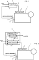
- Figure 1 illustrates an example of a prior art speed controller 4 for a piston engine 1.
- the speed of the piston engine's main shaft is measured using sensor 2 on the flywheel 3, for example.
- the measurement data from the sensor is forwarded to the speed controller 4, which compares the measured speed with the reference speed.
- the speed controller issues control signals to an actuator or actuators 5 in the engine in order to adjust the engine speed (more precisely the rotational speed of the engine's main shaft) to a desired value known as the reference speed value.
- the speed controller comprises a first interface 6 for receiving reference data (the reference signal), a second interface 7 for receiving measurement data (the measurement signal), and a third interface 8 for transmitting a control signal to the actuator.
- the actuator is usually a valve regulating the quantity of fuel supplied into the engine, or the control signal may control the cylinder-specific fuel injectors.
- US 20060011167 discloses a known PI controller wherein two feedback loops are used to provide two difference signals into the controller.
- a speed controller is required to keep the engine speed at the desired value and within the desired range. If there is no speed controller, the engine speed may deviate from the intended operating range, and this may lead to engine damage.
- a speed controller normally uses a PID algorithm. The controller is usually tuned so that the engine speed would deviate as little as possible with changing engine load, and that the engine speed would not oscillate at a stable speed. If the controller is tuned to respond rapidly to changes in engine load, the engine speed will easily oscillate at even load - that is, when operating the engine at a stable speed. On the other hand, if the controller is tuned to completely or almost completely eliminate oscillation of the engine speed at a stable speed, the controller will be slow to respond to changes in engine load.
- the tuning would only operate appropriately under the conditions prevalent at the time of tuning.
- the conditions prevalent in an engine change for many reasons, such as wear and tear of the engine's mechanical components, variations in engine load, variations in the quality of fuel, variations in environmental conditions, changes in the temperature of a flexible coupling linked to the engine shaft, etc.
- engine control becomes either more oscillatory or slower.
- a PID controller (or other type of controller) must be tuned in practice without more detailed informational or theoretical support.
- an oscillating engine constitutes a serious problem because oscillation speeds up wear and tear on the engine.
- the engine is usually linked to the load (ship's generator, ship's propeller) through a flexible coupling.
- the coupling attenuates the natural oscillation of the engine, caused by crankshaft rotation.
- Crankshaft oscillation is due to the nonsimultaneous power strokes of the pistons connected to the crankshaft, which provide energy from the consumption of fuel.
- the flexible coupling is dimensioned to bear the normal oscillation and power of the engine.
- the oscillation caused by the operation of the engine speed controller is substantially larger in magnitude compared to the engine's natural oscillation.
- the situation is particularly severe when the frequencies of the engine's natural oscillations and the oscillations caused by control occur at the resonant frequency of the engine system (engine, coupling and system main shaft with load).
- the resonant system may damage system components.
- the flexible coupling is a component that will be likely to break.
- Oscillation caused by control thus imposes additional stress on the flexible coupling. Additional stress increases the temperature of the internals of the coupling, which reduces its service life and, at worst, may cause damage to the coupling. Breakdown of the flexible coupling during operation may correspondingly cause damage to the engine and/or load.
- the objective of the invention is to reduce oscillations in the rotational speed of an engine caused by the speed controller.
- the objective will be achieved through a speed controller for controlling the speed of a piston engine according to claim 1.
- the piston engine speed controller of the present invention can analyse the oscillations it is causing and take the necessary action on this basis.
- FIG. 2 illustrates an example of an embodiment 9 of the invention.
- the speed controller 9 according to the invention comprises a speed controller section 4 (controller) and a monitoring section 10.
- the controller 4 is a normal speed controller of any known controller type, such as PID controller etc.
- the controller 4 has a first interface 6 for receiving reference data, a second interface 7 for receiving measurement data of the engine speed (more precisely the rotational speed), and a third interface 8 for transmitting a control signal to control the speed of the piston engine.
- the controller section 4 is arranged to generate said control signal in response to the received measurement data and reference data.
- the purpose of the monitoring section 10 is to monitor the responses in engine speed caused by the actions of the speed controller 4.
- the monitoring section comprises a fourth interface 11 for receiving measurement data of the engine speed, a fifth interface 12 for transmitting a control change signal to the controller 4, and a sixth interface 13 for transmitting a message regarding the response in engine speed caused by controller operation.
- the monitoring section is thus arranged to generate a control change signal to control the controller 4 through the fifth interface 12 as necessary, and to generate a message regarding the response caused by controller operation for transmission through the sixth interface 13 as necessary.
- the message to be transmitted is an alarm of a certain level or a message of a lower level.
- the message shall be received, for example, at a separate monitoring centre where a supervisor can react to the message as considered appropriate.
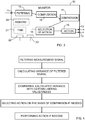
- FIG. 3 illustrates the monitoring section 10 in more detail.
- the monitoring section 10 comprises a filter 15 for filtering the highest frequencies and the direct current component from the measurement data signal, a computation element 16 for calculating the values corresponding to a certain quantity or quantities from the filtered measurement data signal, a comparison element 17 for comparing the calculated values with a certain limit or limits, a selection element 18 for selecting the appropriate action on the basis of the comparison, and action elements 19 for carrying out the selected action(s).
- the filter section 15 can be, for example, an analogue low-pass filter or a digital filter such as a FIR filter.
- the implementation of the filter section depends on the intended way of constructing the monitoring section - with analogue components or digital components.
- the computation element 16 is arranged to calculate the values of a quantity or quantities.
- the computation element (16) calculates the variance value.
- Variance represents deviation of the signal in relation to its expected value.
- Formula (1) means that the average of the squares of the differences constitutes the expected value of deviation, also known as the variance. There are naturally also other ways of determining variance.
- the engine's natural oscillations cause variance in the engine speed compared to a completely non-oscillating speed. Uneven wear on the engine's cylinder also increases variance in engine speed. Thus the variance value is dependent on the quantity of oscillation and therefore the state of the engine. Conventional variance values in different states of the engine can be determined in advance.
- the operation of the controller 4 causes high variance values for engine speed.
- a comparison of the variance values calculated by the monitoring section 10 with predetermined conventional variance values makes it possible to conclude whether controller operation has caused oscillations in engine speed to a harmful extent.
- the comparison element 17 compares the calculated variance with predetermined values. A comparison can be made by comparing the values with each other or by calculating the difference of the values. On the basis of the comparison, the selection element chooses the way of action. If the value stored in advance is less than the calculated value, the generation of a message and/or control signal is chosen. There may be several values stored in advance, and the action chosen may depend on how many stored values are exceeded by the calculated value. The stored values can thus serve as limits, and certain actions will be taken when the limits are exceeded. The limits can be set so that the monitoring section 10 will not be too sensitive to control the operation of the controller section 4. If the difference between the calculated value and stored value is used for comparison, the magnitude of the difference is the criterion for choosing the way of action.
- Messages and control signals can be generated.
- Messages and control signals can be used separately or jointly to generate a way of action.
- the action elements 19 are arranged to generate the chosen control change signal to control the speed controller 4 and to generate a message regarding the response caused by controller operation.
- the action elements can be a single entity or one consisting of several parts.
- the monitoring section also comprises a timing arrangement 21 arranged to provide time information (for time stamps) to other parts of the controller, and a seventh interface 22 to receive information of each control action executed by the controller 4.
- the computation element 16 is arranged to attach a time stamp to the calculated value, and an appropriate part of the monitoring section 10, such as the interface 22, is arranged to attach a time stamp to the action data of the controller 4.
- the comparison element 17 and the selection element 18 are arranged to utilise said time stamps to select action. If the time stamp of calculated variance is close to the time stamp of control action by the controller 4, accounting for the time constants of the engine and controller, it can be concluded more precisely that control action has caused oscillation in engine speed.
- the presented embodiments also contain section-specific memory capacity or a separate memory 20 that stores necessary information (values stored in advance, information on control actions executed by the controller 4, values of calculated quantities and time stamps attached to data).
- the controller section 4 must also have an arrangement for sending information on control action to the monitoring section 10.
- the arrangement can be a separate interface through which said data is forwarded to the seventh interface in the monitoring section, or the control change signal can also be forwarded to the monitoring section.
- the dotted line in Figure 2 illustrates this arrangement.
- FIGS 2 and 3 illustrate embodiments of the invention in very simplified form. It shall be kept in mind that practical embodiments can be implemented in several different ways and may contain parts and functions not illustrated in Figures 2 and 3 .
- the monitoring section can be implemented so that at least the computation element 16, the comparison element 17 and the selection element 18 are software entities intended to be executed in the monitoring section's processing unit.
- the software entity may be a separate program or a subpart of a larger program.
- the monitoring section 10 in its entirety may also be a circuit board, such as a circuit board comprising an ASIC (Application Specific Integrated Circuit).
- ASIC Application Specific Integrated Circuit
- the monitoring section may also comprise an eighth interface 23 through which the monitoring section can be reconfigured as necessary.
- the speed controller according to the invention is able to analyse the dynamic behaviour of the controller and engine in a simple and reliable way and to distinguish between engine speed oscillations caused by controller operation and the natural oscillations of the engine. No complex and detailed modelling of the engine needs to be known.
- the invention is well-suited to be used as a speed controller for ship engines.
- the invention can be implemented as a PID controller or other type of controller.
Landscapes
- Engineering & Computer Science (AREA)
- Software Systems (AREA)
- General Physics & Mathematics (AREA)
- Automation & Control Theory (AREA)
- Medical Informatics (AREA)
- Physics & Mathematics (AREA)
- Computer Vision & Pattern Recognition (AREA)
- Health & Medical Sciences (AREA)
- Artificial Intelligence (AREA)
- Evolutionary Computation (AREA)
- Combustion & Propulsion (AREA)
- Chemical & Material Sciences (AREA)
- General Engineering & Computer Science (AREA)
- Mechanical Engineering (AREA)
- Microelectronics & Electronic Packaging (AREA)
- Computer Hardware Design (AREA)
- Combined Controls Of Internal Combustion Engines (AREA)
- Control Of Electric Motors In General (AREA)
Claims (9)
- Drehzahlsteuerung (4) zur Steuerung der Drehzahl eines Kolbenmotors, die Drehzahlsteuerung umfassend eine erste Schnittstelle (6) zum Empfang von Referenzdaten, eine zweite Schnittstelle (7) zum Empfang von Messdaten zur Motordrehzahl und eine dritte Schnittstelle (8) zur Übertragung eines Steuersignals, um die Drehzahl des Kolbenmotors zu steuern, und wobei die Drehzahlsteuerung eingerichtet ist, das Steuersignal in Reaktion auf die empfangenen Messdaten und Referenzdaten zu erzeugen, wobei die Drehzahlsteuerung einen Überwachungsabschnitt (10) zur Überwachung der Reaktionen der Motordrehzahl umfasst, die von der Drehzahlsteuerung (4) bewirkt werden, der Überwachungsabschnitt umfassend eine vierte Schnittstelle (11) zum Empfang von Messdaten der Motordrehzahl, und eine fünfte Schnittstelle (12) zur Übertragung eines Steuerungsänderungssignals an die Steuerung (4),
wobei der Überwachungsabschnitt (10) eingerichtet ist, ein Steuerungsänderungssignal zu erzeugen, um die Drehzahlsteuerung (4) durch die fünfte Schnittstelle (12) zu steuern,
dadurch gekennzeichnet, dass der Überwachungsabschnitt (10) ferner eine sechste Schnittstelle (13) zur Übertragung einer Alarmnachricht an ein Überwachungszentrum hinsichtlich der Reaktion der Motordrehzahl, die von dem Betrieb der Steuerung bewirkt wird, umfasst,
und dadurch, dass der Überwachungsabschnitt (10) ferner einen Filter (15) zur Filterung der höchsten Frequenzen und der Direktsignalkomponente aus dem Messdatensignal umfasst, ein Berechnungselement (16) zur Berechnung von Werten, die ein bestimmten Menge oder Mengen aus dem gefilterten Messdatensignal entsprechen, ein Vergleichselement (17) zum Vergleichen der berechneten Werte mit einer bestimmten Grenze oder Grenzen, ein Auswahlelement (18) zur Auswahl einer Erzeugung des Steuerungsänderungssignals auf Grundlage des Vergleichs, sowie Aktionselemente (19) zur Durchführung der ausgewählten Erzeugung des Steuerungsänderungssignals, wobei die berechneten Werte Varianzwerte sind,
der Überwachungsabschnitt (10) ferner umfassend eine siebte Schnittstelle (22) zum Empfang von Informationen jeder Steuerungsaktion, die von der Steuerung (4) ausgeführt wird, und die Steuerung (4) eine Einrichtung zur Übertragung von Informationen jeder Steuerungsaktion an die siebte Schnittstelle umfasst,
und dadurch, dass das Berechnungselement (16) eingerichtet ist, einen Zeitstempel an den berechneten Wert anzubringen, und der Überwachungsabschnitt eingerichtet ist, einen zweiten Zeitstempel an jeder empfangenen Steuerungsaktionsangabe anzubringen,
und das Vergleichselement (17) und das Auswahlelement (18) eingerichtet sind, die Zeitstempel zu nutzen, um die Erzeugung des Steuerungsänderungssignals auszuwählen. - Steuerung nach Anspruch 1, dadurch gekennzeichnet, dass die Aktionselemente (19) eingerichtet sind, das Steuerungsänderungssignal zu erzeugen, um die Drehzahlsteuerung (4) zu steuern und eine Nachricht hinsichtlich der Reaktion, die von dem Betrieb der Steuerung bewirkt wird, zu erzeugen.
- Steuerung nach Anspruch 2, dadurch gekennzeichnet, dass das Steuerungsänderungssignal, das erzeugt wird, eingerichtet ist, die Referenzdaten zu ändern, die von der Steuerung genutzt werden.
- Steuerung nach einem der Ansprüche 2 bis 3, dadurch gekennzeichnet, dass die Steuerung eine Zeitgebereinrichtung (21) umfasst, die eingerichtet ist, Zeitinformationen anderen Teilen der Steuerung bereitzustellen.
- Steuerung nach einem der Ansprüche 2 bis 4, dadurch gekennzeichnet, dass sie Speicher umfasst.
- Steuerung nach einem der Ansprüche 2 bis 5, dadurch gekennzeichnet, dass zumindest das Berechnungselement (16), das Vergleichselement (17) und das Auswahlelement (18) Softwareeinheiten sind.
- Steuerung nach einem der Ansprüche 1 bis 5, dadurch gekennzeichnet, dass der Überwachungsabschnitt (10) eine Platine ist.
- Steuerung nach einem der Ansprüche 1 bis 7, dadurch gekennzeichnet, dass die Drehzahlsteuerung eine PID-Steuerung ist.
- Steuerung nach einem der Ansprüche 1 bis 8, dadurch gekennzeichnet, dass der Überwachungsabschnitt eingerichtet ist, eine Nachricht hinsichtlich der Reaktion, die von dem Betrieb der Steuerung bewirkt wird, zur Übertragung durch die sechste Schnittstelle (13) zu erzeugen.
Applications Claiming Priority (2)
| Application Number | Priority Date | Filing Date | Title |
|---|---|---|---|
| FI20085202A FI125798B (fi) | 2008-03-03 | 2008-03-03 | Mäntämoottorin nopeussäädin |
| PCT/FI2009/050173 WO2009109702A1 (en) | 2008-03-03 | 2009-03-02 | Speed controller for piston engine |
Publications (2)
| Publication Number | Publication Date |
|---|---|
| EP2247840A1 EP2247840A1 (de) | 2010-11-10 |
| EP2247840B1 true EP2247840B1 (de) | 2019-05-01 |
Family
ID=39269498
Family Applications (1)
| Application Number | Title | Priority Date | Filing Date |
|---|---|---|---|
| EP09718195.2A Active EP2247840B1 (de) | 2008-03-03 | 2009-03-02 | Drehzahlsteuerungsgerät für einen kolbenmotor |
Country Status (3)
| Country | Link |
|---|---|
| EP (1) | EP2247840B1 (de) |
| FI (1) | FI125798B (de) |
| WO (1) | WO2009109702A1 (de) |
Families Citing this family (4)
| Publication number | Priority date | Publication date | Assignee | Title |
|---|---|---|---|---|
| US10495014B2 (en) | 2011-12-29 | 2019-12-03 | Ge Global Sourcing Llc | Systems and methods for displaying test details of an engine control test |
| WO2013101747A1 (en) * | 2011-12-29 | 2013-07-04 | General Electric Company | Apparatus and method for controlling an internal combustion engine |
| AT516817B1 (de) | 2015-01-23 | 2025-12-15 | Innio Jenbacher Gmbh & Co Og | Verfahren zum Betreiben einer Anordnung umfassend eine rotierende Arbeitsmaschine |
| USD800739S1 (en) | 2016-02-16 | 2017-10-24 | General Electric Company | Display screen with graphical user interface for displaying test details of an engine control test |
Family Cites Families (4)
| Publication number | Priority date | Publication date | Assignee | Title |
|---|---|---|---|---|
| JP3170067B2 (ja) * | 1992-10-02 | 2001-05-28 | 株式会社日立製作所 | 内燃機関の希薄燃焼制御装置及びこれを備えた燃料噴射量制御装置 |
| DE10248780A1 (de) * | 2002-10-16 | 2004-04-29 | Volkswagen Ag | Verfahren und Vorrichtung zur Leerlaufregelung bei Verbrennungsmotoren |
| DE10253739B3 (de) | 2002-11-19 | 2004-05-06 | Mtu Friedrichshafen Gmbh | Verfahren zur Drehzahl-Regelung einer Brennkraftmaschine |
| US7235892B2 (en) * | 2005-09-09 | 2007-06-26 | Cummins, Inc. | Load-based quadratic compensator gain adjustment |
-
2008
- 2008-03-03 FI FI20085202A patent/FI125798B/fi not_active IP Right Cessation
-
2009
- 2009-03-02 WO PCT/FI2009/050173 patent/WO2009109702A1/en not_active Ceased
- 2009-03-02 EP EP09718195.2A patent/EP2247840B1/de active Active
Non-Patent Citations (1)
| Title |
|---|
| None * |
Also Published As
| Publication number | Publication date |
|---|---|
| WO2009109702A1 (en) | 2009-09-11 |
| FI125798B (fi) | 2016-02-29 |
| EP2247840A1 (de) | 2010-11-10 |
| FI20085202L (fi) | 2009-09-04 |
| FI20085202A0 (fi) | 2008-03-03 |
Similar Documents
| Publication | Publication Date | Title |
|---|---|---|
| CN101793227B (zh) | 风力涡轮机运行控制方法及风力涡轮机 | |
| US10006441B2 (en) | Management system for operating a wind energy plant and method using the management system | |
| EP2463517B1 (de) | Verfahren sowie Steuersystem zur Reduktion der Schwingungen einer Windenergieanlage | |
| EP2696251B1 (de) | Verfahren zum Überwachen von rotierenden Maschinen | |
| CN103321839B (zh) | 风机振动监测方法及系统、风机监控器 | |
| CN102996265B (zh) | 工程机械设备及其发动机转速控制方法、装置和系统 | |
| EP2410654B1 (de) | Stromnetzfrequenzratenbegrenzungssystem | |
| EP2213873A1 (de) | Abschätzen einer effektiven Windrichtung für eine Windturbine mithilfe eines Lernsystems | |
| CN109891091A (zh) | 动态控制的风力涡轮机关闭 | |
| EP2247840A1 (de) | Drehzahlsteuerungsgerät für einen kolbenmotor | |
| JP2004257388A (ja) | 切迫センサ故障を検出するための方法及び装置 | |
| CN114687953B (zh) | 风力发电机组的振动类型识别方法、控制方法及装置 | |
| CN111396278A (zh) | 电子换向液压机中的阀定时 | |
| US20150333721A1 (en) | Dynamically detecting resonating frequencies of resonating structures | |
| DE102005058547B4 (de) | Einrichtung zur Verminderung von Hydrofluidschwingungen in einem Hydrauliksystem | |
| KR20020035862A (ko) | 건설 기계의 전자 제어 시스템 | |
| CA3096382A1 (en) | Prognostic torsional damper damage determination in machine system | |
| WO2006040287A1 (de) | Schnelldrehende vakuumpumpe | |
| EP2851586A1 (de) | Hydraulikgetriebe | |
| JP4750880B2 (ja) | 舶用エンジン制御システムおよび方法 | |
| US7846063B2 (en) | Automatic calibration of a torque measuring system | |
| CN109642512A (zh) | 内燃机的气缸启停的确定 | |
| EP3949110B1 (de) | Verfahren zum betreiben einer elektrischen maschine unter verwendung einer dynamischen kapazitätskurve und windturbine | |
| CN102425660A (zh) | 一种应用于工程机械的换档控制方法及控制器 | |
| CN115642379B (zh) | 一种风机低频振动传感器的物理低通滤波器 |
Legal Events
| Date | Code | Title | Description |
|---|---|---|---|
| PUAI | Public reference made under article 153(3) epc to a published international application that has entered the european phase |
Free format text: ORIGINAL CODE: 0009012 |
|
| 17P | Request for examination filed |
Effective date: 20100723 |
|
| AK | Designated contracting states |
Kind code of ref document: A1 Designated state(s): AT BE BG CH CY CZ DE DK EE ES FI FR GB GR HR HU IE IS IT LI LT LU LV MC MK MT NL NO PL PT RO SE SI SK TR |
|
| AX | Request for extension of the european patent |
Extension state: AL BA RS |
|
| RIN1 | Information on inventor provided before grant (corrected) |
Inventor name: PENSAR, JOHAN |
|
| DAX | Request for extension of the european patent (deleted) | ||
| 17Q | First examination report despatched |
Effective date: 20130711 |
|
| STAA | Information on the status of an ep patent application or granted ep patent |
Free format text: STATUS: EXAMINATION IS IN PROGRESS |
|
| RAP1 | Party data changed (applicant data changed or rights of an application transferred) |
Owner name: WAERTSILAE FINLAND OY |
|
| GRAP | Despatch of communication of intention to grant a patent |
Free format text: ORIGINAL CODE: EPIDOSNIGR1 |
|
| STAA | Information on the status of an ep patent application or granted ep patent |
Free format text: STATUS: GRANT OF PATENT IS INTENDED |
|
| INTG | Intention to grant announced |
Effective date: 20181120 |
|
| GRAS | Grant fee paid |
Free format text: ORIGINAL CODE: EPIDOSNIGR3 |
|
| GRAA | (expected) grant |
Free format text: ORIGINAL CODE: 0009210 |
|
| STAA | Information on the status of an ep patent application or granted ep patent |
Free format text: STATUS: THE PATENT HAS BEEN GRANTED |
|
| AK | Designated contracting states |
Kind code of ref document: B1 Designated state(s): AT BE BG CH CY CZ DE DK EE ES FI FR GB GR HR HU IE IS IT LI LT LU LV MC MK MT NL NO PL PT RO SE SI SK TR |
|
| REG | Reference to a national code |
Ref country code: GB Ref legal event code: FG4D |
|
| REG | Reference to a national code |
Ref country code: CH Ref legal event code: EP Ref country code: AT Ref legal event code: REF Ref document number: 1127231 Country of ref document: AT Kind code of ref document: T Effective date: 20190515 |
|
| REG | Reference to a national code |
Ref country code: DE Ref legal event code: R096 Ref document number: 602009058111 Country of ref document: DE |
|
| REG | Reference to a national code |
Ref country code: IE Ref legal event code: FG4D |
|
| REG | Reference to a national code |
Ref country code: NL Ref legal event code: MP Effective date: 20190501 |
|
| REG | Reference to a national code |
Ref country code: LT Ref legal event code: MG4D |
|
| PG25 | Lapsed in a contracting state [announced via postgrant information from national office to epo] |
Ref country code: HR Free format text: LAPSE BECAUSE OF FAILURE TO SUBMIT A TRANSLATION OF THE DESCRIPTION OR TO PAY THE FEE WITHIN THE PRESCRIBED TIME-LIMIT Effective date: 20190501 Ref country code: NL Free format text: LAPSE BECAUSE OF FAILURE TO SUBMIT A TRANSLATION OF THE DESCRIPTION OR TO PAY THE FEE WITHIN THE PRESCRIBED TIME-LIMIT Effective date: 20190501 Ref country code: LT Free format text: LAPSE BECAUSE OF FAILURE TO SUBMIT A TRANSLATION OF THE DESCRIPTION OR TO PAY THE FEE WITHIN THE PRESCRIBED TIME-LIMIT Effective date: 20190501 Ref country code: ES Free format text: LAPSE BECAUSE OF FAILURE TO SUBMIT A TRANSLATION OF THE DESCRIPTION OR TO PAY THE FEE WITHIN THE PRESCRIBED TIME-LIMIT Effective date: 20190501 Ref country code: PT Free format text: LAPSE BECAUSE OF FAILURE TO SUBMIT A TRANSLATION OF THE DESCRIPTION OR TO PAY THE FEE WITHIN THE PRESCRIBED TIME-LIMIT Effective date: 20190901 Ref country code: FI Free format text: LAPSE BECAUSE OF FAILURE TO SUBMIT A TRANSLATION OF THE DESCRIPTION OR TO PAY THE FEE WITHIN THE PRESCRIBED TIME-LIMIT Effective date: 20190501 Ref country code: SE Free format text: LAPSE BECAUSE OF FAILURE TO SUBMIT A TRANSLATION OF THE DESCRIPTION OR TO PAY THE FEE WITHIN THE PRESCRIBED TIME-LIMIT Effective date: 20190501 Ref country code: NO Free format text: LAPSE BECAUSE OF FAILURE TO SUBMIT A TRANSLATION OF THE DESCRIPTION OR TO PAY THE FEE WITHIN THE PRESCRIBED TIME-LIMIT Effective date: 20190801 |
|
| PG25 | Lapsed in a contracting state [announced via postgrant information from national office to epo] |
Ref country code: GR Free format text: LAPSE BECAUSE OF FAILURE TO SUBMIT A TRANSLATION OF THE DESCRIPTION OR TO PAY THE FEE WITHIN THE PRESCRIBED TIME-LIMIT Effective date: 20190802 Ref country code: BG Free format text: LAPSE BECAUSE OF FAILURE TO SUBMIT A TRANSLATION OF THE DESCRIPTION OR TO PAY THE FEE WITHIN THE PRESCRIBED TIME-LIMIT Effective date: 20190801 Ref country code: LV Free format text: LAPSE BECAUSE OF FAILURE TO SUBMIT A TRANSLATION OF THE DESCRIPTION OR TO PAY THE FEE WITHIN THE PRESCRIBED TIME-LIMIT Effective date: 20190501 |
|
| REG | Reference to a national code |
Ref country code: AT Ref legal event code: MK05 Ref document number: 1127231 Country of ref document: AT Kind code of ref document: T Effective date: 20190501 |
|
| PG25 | Lapsed in a contracting state [announced via postgrant information from national office to epo] |
Ref country code: IS Free format text: LAPSE BECAUSE OF FAILURE TO SUBMIT A TRANSLATION OF THE DESCRIPTION OR TO PAY THE FEE WITHIN THE PRESCRIBED TIME-LIMIT Effective date: 20190901 |
|
| PG25 | Lapsed in a contracting state [announced via postgrant information from national office to epo] |
Ref country code: DK Free format text: LAPSE BECAUSE OF FAILURE TO SUBMIT A TRANSLATION OF THE DESCRIPTION OR TO PAY THE FEE WITHIN THE PRESCRIBED TIME-LIMIT Effective date: 20190501 Ref country code: AT Free format text: LAPSE BECAUSE OF FAILURE TO SUBMIT A TRANSLATION OF THE DESCRIPTION OR TO PAY THE FEE WITHIN THE PRESCRIBED TIME-LIMIT Effective date: 20190501 Ref country code: EE Free format text: LAPSE BECAUSE OF FAILURE TO SUBMIT A TRANSLATION OF THE DESCRIPTION OR TO PAY THE FEE WITHIN THE PRESCRIBED TIME-LIMIT Effective date: 20190501 Ref country code: SK Free format text: LAPSE BECAUSE OF FAILURE TO SUBMIT A TRANSLATION OF THE DESCRIPTION OR TO PAY THE FEE WITHIN THE PRESCRIBED TIME-LIMIT Effective date: 20190501 Ref country code: RO Free format text: LAPSE BECAUSE OF FAILURE TO SUBMIT A TRANSLATION OF THE DESCRIPTION OR TO PAY THE FEE WITHIN THE PRESCRIBED TIME-LIMIT Effective date: 20190501 Ref country code: CZ Free format text: LAPSE BECAUSE OF FAILURE TO SUBMIT A TRANSLATION OF THE DESCRIPTION OR TO PAY THE FEE WITHIN THE PRESCRIBED TIME-LIMIT Effective date: 20190501 |
|
| REG | Reference to a national code |
Ref country code: DE Ref legal event code: R097 Ref document number: 602009058111 Country of ref document: DE |
|
| PLBE | No opposition filed within time limit |
Free format text: ORIGINAL CODE: 0009261 |
|
| STAA | Information on the status of an ep patent application or granted ep patent |
Free format text: STATUS: NO OPPOSITION FILED WITHIN TIME LIMIT |
|
| PG25 | Lapsed in a contracting state [announced via postgrant information from national office to epo] |
Ref country code: TR Free format text: LAPSE BECAUSE OF FAILURE TO SUBMIT A TRANSLATION OF THE DESCRIPTION OR TO PAY THE FEE WITHIN THE PRESCRIBED TIME-LIMIT Effective date: 20190501 |
|
| 26N | No opposition filed |
Effective date: 20200204 |
|
| PG25 | Lapsed in a contracting state [announced via postgrant information from national office to epo] |
Ref country code: PL Free format text: LAPSE BECAUSE OF FAILURE TO SUBMIT A TRANSLATION OF THE DESCRIPTION OR TO PAY THE FEE WITHIN THE PRESCRIBED TIME-LIMIT Effective date: 20190501 |
|
| PG25 | Lapsed in a contracting state [announced via postgrant information from national office to epo] |
Ref country code: SI Free format text: LAPSE BECAUSE OF FAILURE TO SUBMIT A TRANSLATION OF THE DESCRIPTION OR TO PAY THE FEE WITHIN THE PRESCRIBED TIME-LIMIT Effective date: 20190501 |
|
| PG25 | Lapsed in a contracting state [announced via postgrant information from national office to epo] |
Ref country code: MC Free format text: LAPSE BECAUSE OF FAILURE TO SUBMIT A TRANSLATION OF THE DESCRIPTION OR TO PAY THE FEE WITHIN THE PRESCRIBED TIME-LIMIT Effective date: 20190501 |
|
| REG | Reference to a national code |
Ref country code: CH Ref legal event code: PL |
|
| REG | Reference to a national code |
Ref country code: BE Ref legal event code: MM Effective date: 20200331 |
|
| PG25 | Lapsed in a contracting state [announced via postgrant information from national office to epo] |
Ref country code: LU Free format text: LAPSE BECAUSE OF NON-PAYMENT OF DUE FEES Effective date: 20200302 |
|
| PG25 | Lapsed in a contracting state [announced via postgrant information from national office to epo] |
Ref country code: IE Free format text: LAPSE BECAUSE OF NON-PAYMENT OF DUE FEES Effective date: 20200302 Ref country code: LI Free format text: LAPSE BECAUSE OF NON-PAYMENT OF DUE FEES Effective date: 20200331 Ref country code: CH Free format text: LAPSE BECAUSE OF NON-PAYMENT OF DUE FEES Effective date: 20200331 Ref country code: FR Free format text: LAPSE BECAUSE OF NON-PAYMENT OF DUE FEES Effective date: 20200331 |
|
| PG25 | Lapsed in a contracting state [announced via postgrant information from national office to epo] |
Ref country code: BE Free format text: LAPSE BECAUSE OF NON-PAYMENT OF DUE FEES Effective date: 20200331 |
|
| GBPC | Gb: european patent ceased through non-payment of renewal fee |
Effective date: 20200302 |
|
| PG25 | Lapsed in a contracting state [announced via postgrant information from national office to epo] |
Ref country code: GB Free format text: LAPSE BECAUSE OF NON-PAYMENT OF DUE FEES Effective date: 20200302 |
|
| PG25 | Lapsed in a contracting state [announced via postgrant information from national office to epo] |
Ref country code: MT Free format text: LAPSE BECAUSE OF FAILURE TO SUBMIT A TRANSLATION OF THE DESCRIPTION OR TO PAY THE FEE WITHIN THE PRESCRIBED TIME-LIMIT Effective date: 20190501 Ref country code: CY Free format text: LAPSE BECAUSE OF FAILURE TO SUBMIT A TRANSLATION OF THE DESCRIPTION OR TO PAY THE FEE WITHIN THE PRESCRIBED TIME-LIMIT Effective date: 20190501 |
|
| PG25 | Lapsed in a contracting state [announced via postgrant information from national office to epo] |
Ref country code: MK Free format text: LAPSE BECAUSE OF FAILURE TO SUBMIT A TRANSLATION OF THE DESCRIPTION OR TO PAY THE FEE WITHIN THE PRESCRIBED TIME-LIMIT Effective date: 20190501 |
|
| PGFP | Annual fee paid to national office [announced via postgrant information from national office to epo] |
Ref country code: DE Payment date: 20260319 Year of fee payment: 18 |
|
| PGFP | Annual fee paid to national office [announced via postgrant information from national office to epo] |
Ref country code: IT Payment date: 20260324 Year of fee payment: 18 |