EP2247364B1 - Filterelement mit griff - Google Patents
Filterelement mit griff Download PDFInfo
- Publication number
- EP2247364B1 EP2247364B1 EP09714966.0A EP09714966A EP2247364B1 EP 2247364 B1 EP2247364 B1 EP 2247364B1 EP 09714966 A EP09714966 A EP 09714966A EP 2247364 B1 EP2247364 B1 EP 2247364B1
- Authority
- EP
- European Patent Office
- Prior art keywords
- filter
- bellows
- filter element
- arrangement
- element according
- Prior art date
- Legal status (The legal status is an assumption and is not a legal conclusion. Google has not performed a legal analysis and makes no representation as to the accuracy of the status listed.)
- Not-in-force
Links
Images


Classifications
-
- B—PERFORMING OPERATIONS; TRANSPORTING
- B01—PHYSICAL OR CHEMICAL PROCESSES OR APPARATUS IN GENERAL
- B01D—SEPARATION
- B01D46/00—Filters or filtering processes specially modified for separating dispersed particles from gases or vapours
- B01D46/24—Particle separators, e.g. dust precipitators, using rigid hollow filter bodies
- B01D46/2403—Particle separators, e.g. dust precipitators, using rigid hollow filter bodies characterised by the physical shape or structure of the filtering element
- B01D46/2411—Filter cartridges
-
- B—PERFORMING OPERATIONS; TRANSPORTING
- B01—PHYSICAL OR CHEMICAL PROCESSES OR APPARATUS IN GENERAL
- B01D—SEPARATION
- B01D46/00—Filters or filtering processes specially modified for separating dispersed particles from gases or vapours
- B01D46/0001—Making filtering elements
-
- B—PERFORMING OPERATIONS; TRANSPORTING
- B01—PHYSICAL OR CHEMICAL PROCESSES OR APPARATUS IN GENERAL
- B01D—SEPARATION
- B01D46/00—Filters or filtering processes specially modified for separating dispersed particles from gases or vapours
- B01D46/0039—Filters or filtering processes specially modified for separating dispersed particles from gases or vapours with flow guiding by feed or discharge devices
- B01D46/0047—Filters or filtering processes specially modified for separating dispersed particles from gases or vapours with flow guiding by feed or discharge devices for discharging the filtered gas
-
- B—PERFORMING OPERATIONS; TRANSPORTING
- B01—PHYSICAL OR CHEMICAL PROCESSES OR APPARATUS IN GENERAL
- B01D—SEPARATION
- B01D46/00—Filters or filtering processes specially modified for separating dispersed particles from gases or vapours
- B01D46/42—Auxiliary equipment or operation thereof
- B01D46/4227—Manipulating filters or filter elements, e.g. handles or extracting tools
-
- B—PERFORMING OPERATIONS; TRANSPORTING
- B01—PHYSICAL OR CHEMICAL PROCESSES OR APPARATUS IN GENERAL
- B01D—SEPARATION
- B01D46/00—Filters or filtering processes specially modified for separating dispersed particles from gases or vapours
- B01D46/52—Particle separators, e.g. dust precipitators, using filters embodying folded corrugated or wound sheet material
- B01D46/521—Particle separators, e.g. dust precipitators, using filters embodying folded corrugated or wound sheet material using folded, pleated material
- B01D46/522—Particle separators, e.g. dust precipitators, using filters embodying folded corrugated or wound sheet material using folded, pleated material with specific folds, e.g. having different lengths
-
- B—PERFORMING OPERATIONS; TRANSPORTING
- B01—PHYSICAL OR CHEMICAL PROCESSES OR APPARATUS IN GENERAL
- B01D—SEPARATION
- B01D46/00—Filters or filtering processes specially modified for separating dispersed particles from gases or vapours
- B01D46/52—Particle separators, e.g. dust precipitators, using filters embodying folded corrugated or wound sheet material
- B01D46/521—Particle separators, e.g. dust precipitators, using filters embodying folded corrugated or wound sheet material using folded, pleated material
- B01D46/523—Particle separators, e.g. dust precipitators, using filters embodying folded corrugated or wound sheet material using folded, pleated material with means for maintaining spacing between the pleats or folds
-
- F—MECHANICAL ENGINEERING; LIGHTING; HEATING; WEAPONS; BLASTING
- F02—COMBUSTION ENGINES; HOT-GAS OR COMBUSTION-PRODUCT ENGINE PLANTS
- F02M—SUPPLYING COMBUSTION ENGINES IN GENERAL WITH COMBUSTIBLE MIXTURES OR CONSTITUENTS THEREOF
- F02M35/00—Combustion-air cleaners, air intakes, intake silencers, or induction systems specially adapted for, or arranged on, internal-combustion engines
- F02M35/02—Air cleaners
- F02M35/024—Air cleaners using filters, e.g. moistened
-
- B—PERFORMING OPERATIONS; TRANSPORTING
- B01—PHYSICAL OR CHEMICAL PROCESSES OR APPARATUS IN GENERAL
- B01D—SEPARATION
- B01D2275/00—Filter media structures for filters specially adapted for separating dispersed particles from gases or vapours
- B01D2275/20—Shape of filtering material
- B01D2275/208—Oval shape
Definitions
- the present invention relates to a filter element with handle and more particularly to a filter element with handle, which has better handling and increased efficiency.
- the combustion air required for internal combustion engines is usually cleaned prior to feeding into the combustion chamber in order to increase the performance and service life of the internal combustion engine.
- an air filter assembly is often used for the purification of the combustion air. This is particularly important for internal combustion engines that operate in an environment that is exposed to a special pollution load of the ambient air, such as in the field of construction or agriculture. Particularly in the field of construction or in agriculture occurs sometimes very high levels of dust, which makes it necessary to clean the combustion air. Due to the fact that the spectrum of the dust particle size is not previously known as a rule, an air filter assembly must be designed so that all particle sizes that can affect the operation of the internal combustion engine in any way, can be reliably filtered out to supply a sufficiently clean combustion air to allow the internal combustion engine. From the US 2007/0113525 A1 a filter system with a filter element is known, which has a grip area on an end plate.
- the present invention has the object to provide a filter element which has an improved efficiency and at the same time allows easy handling.
- a filter element is provided with a filter bellows arrangement with a first filter bellows with a substantially axial direction of expansion and a plane extending in a substantially orthogonal radial expansion direction, a handle and a Leit lake extract, wherein the Filterfaltenbalgan extract forms at least one boundary surface of a Anströmkanals over which the Filter element is flown, wherein the guide surface arrangement is designed to bring a fluid flow directed to the filter bellows assembly, and wherein the handle is integrated into the guide surface arrangement.
- a filter element with a baffle arrangement and a handle can be provided and a space-optimized geometry for a filter element can be provided by the integrative arrangement of the handle and the baffle arrangement.
- a filter element has due to the Leitdonan Mr. an embodiment of the handle assembly such that the filter element can be easily and easily removed from an air filter housing, with the handle and the contact of the operating personnel with the Fulcrum arrangement is taken into account, so that it is made correspondingly stable and robust.
- the integrative design of the handle and the guide surface arrangement allows a space-saving Arrangement, since no additional space for either an additional handle or an additional guide surface arrangement must be provided.
- the guide surface arrangement has a passage in a direction transverse to the axial extension direction.
- Such a penetration allows the engagement in the guide surface arrangement in order to remove the filter element on the guide surface arrangement and the handle formed by the passage from its operating position or to be able to spend in the operating position.
- This increases the handling of the filter element and prevents any untrained operator attacks the filter element at locations that may be sensitive, in particular the outer lateral surfaces of a bellows.
- the operator often acts with gloves and takes a possible damage to the bellows not true. Therefore, a predefined grip position is helpful to protect the filter element from accidental damage.
- the integration of a penetration in a guide surface arrangement thereby eliminates the provision of a separate handle, which would additionally increase the design of a filter element.
- the filter bellows arrangement has a first filter bellows with filter folds extending substantially in an axial direction of expansion of the filter element and a second filter bellows with filter folds extending substantially in an axial direction of expansion of the filter element, the second filter bellows being arranged radially inwardly to the first filter bellows is.
- an inflow or outflow channel is provided between the first filter bellows and the second filter bellows, which allows a planned approach or removal of the filtered or filtered fluid.
- the guide surface arrangement can be arranged so that it allows the supply or discharge into or out of the inlet or outlet channel thus formed. In this way, a compact design is possible while maintaining a high efficiency of the air filter, which is characterized in particular by a low flow resistance.
- the filter folds of the second filter bellows are inclined at least in sections relative to the filter folds of the first filter bellows in an axial expansion direction.
- an inner bellows in a plane of the radial expansion direction has a first bent portion and a second bent portion with a first substantially straight portion therebetween and a second substantially straight portion, respectively.
- a filter bellows with a substantially oval cross-sectional geometry which allows a particularly high efficiency with respect to the design.
- a filter element with such a filter bellows can be made particularly compact.
- the first straight section is connected to the second straight section with a first seal member such that a clean gas side and a raw gas side of the second filter bellows are mis-sealed from each other.
- a central outflow or inflow channel is formed on the inlet and outlet channel formed between the first and the second filter bellows opposite side, wherein formed between this central outflow or inflow and between the first and the second filter bellows An- or outflow a fluid exchange with a filtering takes place.
- a further outflow or Anströmkanal can be formed between the outer surface of the first filter bellows and an air filter housing into which the filter element can be used. In this case, there is also between this between the air filter housing and the first filter bellows exhaust or Anströmkanal and lying between the first and second filter bellows inlet and outlet a fluid exchange with filtering.
- a guide surface arrangement extending in the axial expansion direction is arranged on the first sealing element and is designed to laterally deflect a fluid flow flowing onto the first sealing element.
- the sealing elements are necessary to provide a leak-tight separation between a raw gas side and a clean gas side, such sealing elements often being in the flow path of the fluid flow.
- a baffle arrangement which guides the fluid flow laterally past the sealing element thus increases the efficiency of the filtering performance by reducing the flow resistance.
- smooth transitions can be created in which a fluid flow does not impinge directly on the surfaces of the sealing elements, which often extend transversely to the flow direction.
- an edge limiting the penetration in the upstream direction is designed such that a fluid flow can be conducted away substantially via an edge delimiting the penetration in the downstream direction.
- the limiting edge in the upstream direction viewed from the direction of flow extends beyond the Druchgriff in the downstream direction limiting edge, so that a flow is passed over the edge limiting in the downstream direction.
- the edge bounding in the upstream direction does not necessarily have to project beyond the edge delimiting in the downstream direction. Rather, the airfoil assembly above the upstream edge may be configured to pass fluid flow past the downstream edge.
- the design and positioning of the edge is un Depending on the circumstances with which planned speed, the fluid flows to the guide surface arrangement. In any case, it should be avoided in this way that the fluid flow impinges on the edge bounding in the downstream direction in such a way that a fluid flow is decelerated or even redirected into the penetration.
- the first sealing element extends only partially over a depth of the second filter folds of the second filter bellows in a plane of the radial expansion direction.
- the first sealing element in this embodiment extends only partially over the depth of the second filter folds
- the second filter folds on the inwardly facing side in the region of the end face are glued or glued together so that a false air-tight separation between the raw gas side and the clean gas side ensured is.
- the opposite side of the filter folds remains free, in particular in the region of the end face, so that the end face or the area between the filter folds is also available as inflow and the inflow passage is not through the inner circumferential surface of the first Filterfaltenbalges and the outer surface of the second Filter bellows is limited, but also the areas between the filter folds of the opposite sides of the adhesive is available.
- the guide surface arrangement can be made substantially narrower, since this only has to pass over the sealing element extending only partially over the depth of the second filter folds and not over the entire depth of the second filter folds of the second filter bellows.
- the first filter bellows and the second filter bellows are connected to each other at a second axial end with a second sealing member such that the clean gas and the raw gas sides of the first filter bellows and the second filter bellows are misleaf-tightly separated from each other.
- the second sealing element may extend either over the full depth of the filter pleats of both the first filter bellows and the second filter bellows, but may also be configured so that the sealing element extends only partially over the depth of the first filter bellows or the depth of the second filter bellows.
- a corresponding bonding of the interstices of the filter folds in the region of the end face prevents unfiltered passage of the fluid from the raw gas side to the clean gas side.
- the second sealing element can serve as edge protection, so that the filter element can be prevented from accidental damage, in particular the exposed edges of the filter folds.
- the first filter bellows is provided at a first axial end with a respect to an outer edge of the first Filterfaltenbalges form repertoireden shell.
- Such a shape-preserving shell can serve, for example, for receiving and sealing the outer edge of the first filter bellows and at the same time provide a receptacle for a seal in order to seal the filter element either with respect to the air filter housing and / or with respect to a prefilter element or a downstream safety filter element.
- a sliding surface arrangement can be provided on the shape-preserving shell, which introduces an inflowing fluid flow into the inflow channels or leads out of the outflow channel with little turbulence.
- the baffle arrangement is arranged on the shape-retaining shell and extends in the axial extension direction, wherein the handle is arranged on the shape-retaining shell.
- the arrangement of a handle on the shape-preserving shell deformation of the filter element can be substantially prevented by a force applied to the handle, since the shape-preserving shell ensures a uniform force distribution and prevents sharpening forces may tear apart the filter folds inside and thus cause damage, the one unfiltered passage of the fluid from the raw gas side to the clean gas side would result.
- the guide surface arrangement has a passage with a connection to a flow channel formed from the pleated filter arrangement.
- the inflowing air can flow around the handle formed by the passage, so as to flow back behind the penetration again, so that an underlying opening of an inflow channel can be achieved by the flowed fluid.
- the guide surface arrangement is arranged in the radial direction next to the filter bellows arrangement and extends substantially in the direction of the axial extension direction.
- a handle allows the removal of the filter element transversely to the flow direction, in particular when the air filter housing has a lateral opening for removal of the filter element.
- a handle may be arranged so that it does not lie directly in front of the inflow channels or the outflow channels of the filter element.
- a tapered inflow channel geometry that goes around the circumference can thus be provided along the circumference of the filter element, which enables uniform flow and flow through the first filter bellows in the radially inward direction.
- the guide surface arrangement is spaced from the lateral surface of the Filterfaltenbalgan eleven.
- the guide surface arrangement can be arranged on the outer lateral surface of the first filter bellows in such a way that it serves as a guide surface arrangement for a tangential flow which, on the one hand, permits a distribution of the tangentially impinged air over a certain circumferential area and at the same time lies with the lateral surface of the surface under the guide surface arrangement first filter bellows forms a nozzle assembly, which allows a special support of the tangential flow.
- the guide surface arrangement has a recess for engaging behind.
- Such a recess allows removal of the filter element from an air filter housing transversely to the axial flow direction.
- a corresponding recess allows the engagement and thus the secure holding of the filter element and a possible application of force to pull out the filter element from a possibly existing sealing arrangement.
- the handle has a grid structure, wherein the grid structure has channel-shaped recesses which extend substantially in a fluid flow direction.
- the handle can be made stable by means of a grid structure, but provides no or only a significantly lower flow resistance than an arrangement without a handle.
- the fluid flow can flow through the channel-shaped recesses of the handle substantially without major detours and thus reach the correspondingly provided inflow openings.
- the channel-shaped recesses have inlet edges which have a flow-optimized geometry with respect to a channel inlet.
- channel inlet edges are sharp-edged.
- such edges may be reinforced such that, in particular, gloved operation does not cause damage to the channel inlet edges.
- these channel inlet edges can also be made of a highly flexible material, so that an operator does not contract any injuries, but no damage to the sharp-edged inlet edges occurs during insertion or removal of the filter element.
- FIG. 1 shows a filter element that serves as the basis for a filter element of an exemplary embodiment of the invention.
- This in FIG. 1 shown filter element has an outer bellows 10 and a radially inner lying bellows 20.
- the inner bellows 20 may be inclined to the outer bellows 10, so that between the inner bellows 20 and the outer bellows 10, a discharge or Anströmkanal forms, which widened up here. Due to the inclined position of the second Faltenbalgiatas 20 results in a discharge or Anströmkanal between the two inner circumferential surfaces of the second Faltenbalgettis, which is centrally off and flows.
- the first bellows 10 and the second bellows 20 can be connected to one another, for example, by means of a corresponding sealing element 52, so that, on the one hand, a false-air-tight separation between the raw gas side and the clean gas side occurs and, on the other hand, if the sealing arrangement 52 extends to the outer edge of the sealing arrangement Filter element gives a shock protection.
- the opposing substantially straight sides 28 and 29 of the second bellows member 20 may be interconnected via a first sealing member 51 which, in the embodiment shown here, extends only partially across the depth of the filter pleats.
- the filter folds on the inwardly facing side can be glued together so that a false air-tight separation between the raw gas side and the clean gas side takes place, but the opposite sides of the filter folds remain open on the front side, so that the inflow surface is not limited to the area between the limited inner circumferential surface of the first filter element 10 and the outer circumferential surface of the second filter element 20, but also extends into the interstices of the folds of the second filter element 20 inside. In this way, the inflow area can be significantly increased.
- the filter element further comprises a shape-retaining shell 60 which extends here extends over the entire depth of the first bellows 10.
- this shape-retaining shell may extend only partially from the outside over the depth of the first bellows 10, so that widened at this point, the inflow of the arrival and outflow.
- gripping elements, sealing configurations or guide surface arrangements can be provided on the shape-retaining shell, as will be described below.
- the first bellows element as well as the second bellows element may have an oval peripheral contour, so that in addition to the essentially straight sections 28, 29 there is also a curved section 26 connecting the straight sections. Similarly, such a curved section is also present on the not shown here and cut away side of the filter element.
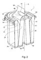
- FIG. 2 shows an exemplary embodiment of the invention, in which the filter element 1 is provided with a guide surface assembly 56 which is connected in the embodiment shown here with a first sealing member 51.
- the guide surface arrangement 56 has a passage 90 which has a front edge 92 lying in the direction of flow and has a rear edge 93 lying downstream in the flow direction.
- the passage 91 forms with the two edges 92 and 93 together a handle 90 which serves to engage, for example, to extract the filter element 1 from a sealing arrangement.
- the guide surface arrangement is designed such that a fluid flowing in the axial extension direction A is guided past the seal arrangement 51 and can enter the flow passage between the first bellows 10 and the second bellows 20 substantially without turbulence.
- edges 92 and 93 are designed such that a substantially turbulence-free or low-turbulence flow through the guide surface arrangement 56 on the first seal member 51 results over.
- a shape-preserving shell 60 is provided, which extends in the embodiment shown here only partially radially inward over the depth of the first bellows 10. In this way, a further inflow surface is available between the filter folds, so that with respect to a shape-preserving over the entire depth of the fold Shell results in an enlarged inflow area, which leads to an increased efficiency of the filter element.
- the second filter bellows 20 is connected to a second sealing arrangement with a second sealing arrangement at a second axial end 22 together with the second axial end 12 of the first filter bellows.
- the second sealing arrangement extends over the entire depth of the first filter pleats 15 of the first bellows and over the entire pleat depth of the second filter pleats 25 of the second bellows 20.
- the seal assembly 52 extends only over the boundary between may extend the first bellows 10 and the second bellows 20 in order to provide in this way also an enlarged Abströmgeometrie can.
- the end faces of the mutually facing fold openings of the first filter folds 15 and the second filter folds 25, namely those facing the interspace of the first bellows 10 and the second bellows 20, may be glued or stitched together, so that a false air-tight separation of a Rohgasraumes of a clean gas room is done.
- the filter element can thus be pulled out of a seal arrangement in the axial direction or pressed into the seal arrangement.
- the baffle arrangement may be made of a hard material and thus may be a hard shell that is placed on top of the first seal configuration.
- the baffle assembly 56 may also be made of a resilient but tough material that allows for appropriate application of force without affecting the geometry of the baffle assembly 56 in a relaxed or resiliently restrained region.
- the baffle arrangement with the integrated recessed grip 91 can be foamed together with the first sealing arrangement 51, so that the seal and the integrated handle guide surface arrangement 90 can be produced in one working step.
- this one for example, on the underside of a circumferential sealing ring on the shape-preserving Shell 60 trained recessed grip include.
- This can be designed so that a one-hand assembly or disassembly of the main filter element, ie the filter element can be done.
- This provides, for example, advantages when replacing a filter element on the air filter of an agricultural machine, such as a combine harvester or a tractor, or a construction machine, in which the operator usually holds with his other hand.
- the main filter element formed as a dual filter bellows may be attached to the second seal assembly 52 at an angular pitch of e.g. 90 ° or 120 ° alignment or centering cam can be formed.
- This can ensure that the filter element, especially in one-handed operation, on the handle 90 always in the correct position, i. is installed and aligned parallel to the longitudinal axis A of the filter housing 100, so that when Axialkraftied to produce the seal, the filter element 1 always remains centered with respect to the axis of the filter housing.
- one of the alignment or centering cams may be split and cooperate with a rib molded in the housing.
- FIG. 12 shows another exemplary embodiment of the invention in which a baffle assembly having an integral handle assembly 56, 90, 91 is disposed on the axially opposite sides of the filter element.
- the guide surface assembly 56 may be placed on the second seal assembly 52 or be formed integrally with her.
- the baffle assembly 56 may be made of a hard material that is placed on the seal assembly 52.
- the guide surface arrangement can be solid as well as hollow chamber material.
- the handle 90 is flowed around by the flow in the axial direction A, so that a part of the inflowing fluid flows behind the handle 90 so as to enter the central inflow channel, which is formed by the inner circumferential surface of the second bellows 20.
- the flowed fluid passes, passed through the guide surface assembly 56, to the outer surface of the first Faltenbalgiatas 10 and flows through this radially inwardly.
- the inflowing fluid passes into the corresponding inflow channels or onto the corresponding inflow surfaces of the first bellows 10 and / or of the second bellows 20 essentially without turbulence or turbulence.
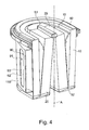
- FIG. 4 shows another exemplary embodiment of the invention in which the baffle assembly 110 is disposed in the radial direction adjacent the filter bellows assembly 10.
- this guide surface arrangement is provided for a tangential flow of the filter element 1.
- this laterally arranged guide surface arrangement 110 can also be used in combination with the guide surface arrangements 56 placed on the sealing elements.
- the guide surface arrangement placed on the first sealing arrangement can be combined with the surface placed on the second sealing arrangement 52 Leit vomanix
- guide surface arrangement also has a handle, with which the filter element 1, for example, laterally, that is, can be removed transversely to the axial flow direction of an air filter housing.
- a front and a rear edge 92, 93 are also provided on the guide surface 110, which can be arranged so that they introduce a fluid flow turbulence-free or turbulence to the outer surface of the Faltenbalgiatas 10.
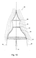
- FIG. 5 shows the in FIG. 4 shown filter element assembly used in an air filter housing 100.
- the in FIG. 5 The view shown is a sectional view transverse to the axial flow direction. It will be in the in FIG. 5
- the fluid to be filtered is introduced tangentially into the air filter housing 100. This can be done, for example, via an upstream Zyk-Ion 140, which filters off as a coarse pre-separator larger dust and dirt particles.
- Zyklonvorabscheider is not absolutely necessary, since the tangential flow also pushes by the centrifugal coarser dust particles to the outside of the wall of the air filter housing, which can be removed via corresponding outlet openings not shown here.
- the filter element 1 has by its oval configuration opposite regions 28, 29 which have a lower curvature and regions 26 and 27 which have a greater curvature.
- the air filter housing has a portion 114 with a small distance of the filter element 1 to the air filter housing 100 and a portion 116 with a large distance of the filter element to the air filter housing 100. These two areas 114 and 116 are connected via a step 115 in which a Inlet opening for the fluid to be filtered is located.
- the fluid flowing in via an inlet opening for example, but not necessarily via an upstream cyclone 140, enters the raw gas space 102 of the air filter and is guided tangentially around the filter element 1.
- the distance between the filter element 1 and the air filter housing 100 may gradually taper along the circumference in the direction of flow, so that the flow cross section gradually decreases along the circumference to the extent that the fluid to be filtered passes radially inwardly through the filter medium of the filter element 1.
- the guide surface arrangement 110 may serve, on the one hand, to pass the air or the fluid flowing through the opening in the step 115 around a cyclic path around the filter element 1 or to prevent turbulence in the inlet region.
- the guide surface arrangement 110 can form a corresponding inflow or inflow at the end of the inflow channel extending along the circumference of the filter element 1, so that a corresponding pressure of the incoming inflow channel also exists in the rear region of the inflow channel between the guide surface arrangement 110 and the actual filter element 1 Fluids is maintained, which leads to a passage of the fluid to be filtered through the filter medium.
- the passage 91 provided in the guide surface arrangement 110 represents a handle through which an operator can remove the filter element 1 from the air filter housing, in particular if the air filter housing has an opening, not shown here, which allows the filter element 1 to be removed transversely to the extension direction is perpendicular to the image plane.
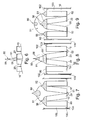
- FIGS. 6 to 9 show exemplary embodiments of Leit vomanix extracten with integrated handle geometries.
- FIG. 6 shows a guide surface assembly 56 which is placed or formed on a first seal assembly 51, wherein the first seal assembly 51 extends only partially beyond the depth of a second fold bellows 20.
- the guide surface arrangement can be made relatively narrow and the handle has only a relatively small width.
- an embodiment of a guide surface arrangement 56 points to a second seal arrangement 52, which lies opposite the first seal arrangement 51 in the axial extension direction.
- the handle 90 may be designed so that it is flowed around by an inflowing fluid, so that a part of the inflowing fluid through the engagement 91 meets the flow channel, which is formed by the inner circumferential surface of the second filter bellows. Another part of the inflowing fluid can pass through the guide surface arrangement into the raw gas chamber region 102 between the outer jacket surface of the filter bellows 10 and the air filter housing 100 and flow through this radially inwards.
- a seal can be done for example via the shape-preserving shell 60 relative to the air filter housing.
- FIG. 8 shows an exemplary embodiment of the invention, in which the guide surface assembly 56 is integrally formed on the first seal member 51 or is placed.
- this geometry corresponds to that with reference to FIG. 6 described geometry, however, the first sealing member 51 extends in the in FIG. 8 shown embodiment over the entire width of the second filter bellows.
- a seal against the air filter housing takes place here also on the shape-preserving shell 60th
- FIG. 9 shows another exemplary embodiment in which a baffle assembly 56, 66 is located on both the mold-retaining shell 60 and the first seal assembly 51.
- a baffle assembly 56, 66 is located on both the mold-retaining shell 60 and the first seal assembly 51.
- FIGS. 6 to 9 the flow through the raw gas space, here in each case from above, while the outflow through the clean gas space, here in each case down, takes place.
- FIG. 7 The arrangement shown essentially corresponds to that with reference to FIG. 3 described embodiment.
- FIG. 8 schematically illustrated embodiment corresponds substantially to the reference to FIG. 2 shown embodiment.
- FIG. 10 shows another exemplary embodiment of a baffle assembly 56 which is mounted on a first seal configuration 51.
- flow lines are symbolized, which symbolize how an inflowing fluid is passed over an upstream bounding edge 52 and substantially turbulence-free or low-turbulence over the passage 91 in the downstream direction limiting edge 93 away.
- edge 92 does not necessarily have to protrude beyond the edge 93, but a geometric configuration is or can be chosen so that a flow line over the edge 93 takes place away.
- FIG. 11 shows a further embodiment of the invention, in which a handle 90 is provided with channel-shaped recesses 96, which extend in the flow direction.
- This channel-shaped Recesses allow an incoming fluid to flow substantially through the handle without having to be routed past the handle on the outside.
- This grid structure 95 essentially leads to a mechanically stable handle construction, but reduces the actual flow resistance of the handle in that the inflowing fluid can flow through the handle substantially.
- Sectional view shown further shows that the boundary edges of the channel-shaped recesses 96 may have a flow-optimized edge geometry 97, so that an inflow of the inflowing fluid into the channel-shaped recesses 96 can be flow-optimized.
- FIG. 11 a schematic arrangement of how such a handle 90 with respect to a passage 91 and a guide surface assembly 56 can be arranged so that the channel-shaped recesses 96 are directed to the guide surface assembly 56 to only in the region of the subjacent control surface arrangement, a division of the inflowing fluid to be able to make.
Landscapes
- Chemical & Material Sciences (AREA)
- Chemical Kinetics & Catalysis (AREA)
- Engineering & Computer Science (AREA)
- Physics & Mathematics (AREA)
- Geometry (AREA)
- Combustion & Propulsion (AREA)
- Mechanical Engineering (AREA)
- General Engineering & Computer Science (AREA)
- Filtering Of Dispersed Particles In Gases (AREA)
- Filtering Materials (AREA)
Applications Claiming Priority (6)
| Application Number | Priority Date | Filing Date | Title |
|---|---|---|---|
| DE102008011186A DE102008011186A1 (de) | 2008-02-26 | 2008-02-26 | Filtereinrichtung, insbesondere Luftfilter für eine Brennkraftmaschine |
| DE102008062956A DE102008062956A1 (de) | 2008-12-23 | 2008-12-23 | Dichtungskonfiguration |
| DE102008062954.5A DE102008062954B4 (de) | 2008-12-23 | 2008-12-23 | Filtereinrichtung, insbesondere Luftfilter für eine Brennkraftmaschine |
| DE102008062953A DE102008062953A1 (de) | 2008-12-23 | 2008-12-23 | Wirkungsgrad erhöhter Mehrfachbalgfilter |
| DE102008062955A DE102008062955A1 (de) | 2008-12-23 | 2008-12-23 | Luftfilter mit Vorabscheider |
| PCT/EP2009/052322 WO2009106594A1 (de) | 2008-02-26 | 2009-02-26 | Filterelement mit griff |
Publications (2)
| Publication Number | Publication Date |
|---|---|
| EP2247364A1 EP2247364A1 (de) | 2010-11-10 |
| EP2247364B1 true EP2247364B1 (de) | 2014-04-23 |
Family
ID=40637786
Family Applications (5)
| Application Number | Title | Priority Date | Filing Date |
|---|---|---|---|
| EP09714966.0A Not-in-force EP2247364B1 (de) | 2008-02-26 | 2009-02-26 | Filterelement mit griff |
| EP09715896.8A Active EP2249944B2 (de) | 2008-02-26 | 2009-02-26 | Filterelement mit optimierter faltenanordnung |
| EP12196545.3A Active EP2574390B1 (de) | 2008-02-26 | 2009-02-26 | Verfahren zur Herstellung eines ovalen Filterbalges |
| EP09716100A Withdrawn EP2257360A1 (de) | 2008-02-26 | 2009-02-26 | Luftfilter mit sicherheitselement |
| EP14197957.5A Withdrawn EP2881158A1 (de) | 2008-02-26 | 2009-02-26 | Filterelement mit optimierter Faltenanordnung |
Family Applications After (4)
| Application Number | Title | Priority Date | Filing Date |
|---|---|---|---|
| EP09715896.8A Active EP2249944B2 (de) | 2008-02-26 | 2009-02-26 | Filterelement mit optimierter faltenanordnung |
| EP12196545.3A Active EP2574390B1 (de) | 2008-02-26 | 2009-02-26 | Verfahren zur Herstellung eines ovalen Filterbalges |
| EP09716100A Withdrawn EP2257360A1 (de) | 2008-02-26 | 2009-02-26 | Luftfilter mit sicherheitselement |
| EP14197957.5A Withdrawn EP2881158A1 (de) | 2008-02-26 | 2009-02-26 | Filterelement mit optimierter Faltenanordnung |
Country Status (4)
| Country | Link |
|---|---|
| EP (5) | EP2247364B1 (pt) |
| CN (2) | CN102015063B (pt) |
| BR (2) | BRPI0907821A2 (pt) |
| WO (3) | WO2009106594A1 (pt) |
Cited By (2)
| Publication number | Priority date | Publication date | Assignee | Title |
|---|---|---|---|---|
| US12415151B2 (en) | 2020-07-03 | 2025-09-16 | Volvo Truck Corporation | Filter housing and an air filter system |
| US12460609B2 (en) | 2020-02-21 | 2025-11-04 | Volvo Truck Corporation | Air filter housing and an air filter element |
Families Citing this family (16)
| Publication number | Priority date | Publication date | Assignee | Title |
|---|---|---|---|---|
| DE102010014277B4 (de) * | 2009-10-12 | 2020-03-12 | Mann+Hummel Gmbh | Filtervorrichtung und Hauptfilterelement für eine Filtervorrichtung |
| DE102009058067A1 (de) * | 2009-12-14 | 2011-06-16 | Mann + Hummel Gmbh | Kompaktfilter, Verfahren zur Herstellung eines Kompaktfilters und Filtermedium |
| DE102012101185B4 (de) * | 2011-08-03 | 2025-07-10 | Gebr. Becker Gmbh | Filterteil |
| DE102012007627B4 (de) | 2012-04-18 | 2023-04-13 | Mann+Hummel Gmbh | Filterelement |
| DE102014000414A1 (de) * | 2013-02-12 | 2014-08-14 | Mann + Hummel Gmbh | Filterkörper |
| EP3157652B1 (de) * | 2014-06-18 | 2020-06-17 | Mann+Hummel GmbH | Filter und filtereinsatz |
| DE102016000575A1 (de) * | 2015-01-30 | 2016-08-04 | Mann+Hummel Gmbh | Hohlfilterelement, Griffeinrichtung eines Hohlfilterelements und Filtervorrichtung mit wenigstens einem Hohlfilterelement |
| US20220297047A1 (en) * | 2015-03-25 | 2022-09-22 | K&N Engineering, Inc. | HVAC Home Air Filter |
| DE102016003456A1 (de) * | 2015-04-10 | 2016-10-13 | Mann + Hummel Gmbh | Filteraufnahme, Filterelement und Filteranordnung |
| DE102016004315A1 (de) | 2016-04-12 | 2017-10-12 | Mann + Hummel Gmbh | Filteranordnung |
| DE102016011754A1 (de) * | 2016-09-30 | 2018-04-05 | Mann+Hummel Gmbh | Filterelement |
| EP3360609A1 (en) * | 2017-02-10 | 2018-08-15 | Mann+Hummel GmbH | Filter element arrangement with an at least doubled safety filter element |
| CN107061070A (zh) * | 2017-02-26 | 2017-08-18 | 郭绍华 | 发动机中空纤维膜空气滤清器滤芯 |
| MX2020005694A (es) | 2017-12-08 | 2020-08-20 | Cummins Filtration Ip Inc | Sello ovalado con contorno de estabilizacion. |
| DE102018000541A1 (de) | 2018-01-24 | 2019-07-25 | Mann+Hummel Gmbh | Filtereinrichtung mit einem Filterelement in einem Filtergehäuse |
| USD884866S1 (en) | 2018-05-08 | 2020-05-19 | Cummins Filtration Ip, Inc. | Filter element |
Family Cites Families (22)
| Publication number | Priority date | Publication date | Assignee | Title |
|---|---|---|---|---|
| US3680286A (en) * | 1970-05-26 | 1972-08-01 | Nefco Filter Corp | Air cleaner |
| US4261710A (en) * | 1979-03-16 | 1981-04-14 | Donaldson Company, Inc. | Two-stage air cleaner and method of preventing contamination of a safety filter |
| DE3628029A1 (de) * | 1986-08-19 | 1988-02-25 | Brita Wasserfilter | Filterpatrone mit verbesserter stroemungsfuehrung |
| DE3918347A1 (de) * | 1989-06-06 | 1990-12-13 | Mann & Hummel Filter | Ansaugluftfilter fuer brennkraftmaschinen |
| DE4203864C2 (de) * | 1992-02-11 | 1993-12-02 | Deere & Co | Positioniereinrichtung für Luftfilter |
| CA2261919A1 (en) * | 1999-02-09 | 2000-08-09 | Wendell E. Ng-See-Quan | Air filter for vehicles |
| US6348077B1 (en) * | 1999-11-19 | 2002-02-19 | Solberg Manufacturing, Inc. | Multiple stage air-intake filter apparatus |
| US6969461B2 (en) * | 2000-01-19 | 2005-11-29 | Baldwin Filters, Inc. | Combination particulate and acid-neutralizing filter |
| US6416561B1 (en) * | 2000-10-20 | 2002-07-09 | Nelson Industries, Inc. | Open flow filter with safety element |
| US6511599B2 (en) * | 2000-12-18 | 2003-01-28 | Nelson Industries, Inc. | Multi-element cylindrical filter with equalized flow |
| DE10222800B4 (de) | 2002-05-23 | 2013-06-27 | Mann + Hummel Gmbh | Filter in einem Filtergehäuse |
| US6833023B1 (en) * | 2003-02-14 | 2004-12-21 | International Liner Co., Inc. | Air filter assembly |
| JP2006035208A (ja) * | 2004-06-23 | 2006-02-09 | Komatsu Ltd | エアクリーナ |
| EP1781398B1 (en) * | 2004-07-20 | 2010-02-17 | Donaldson Company, Inc. | Z-filter media pack arrangement, filter cartridge, air cleaner arrangement and methods |
| US7179315B2 (en) * | 2004-08-04 | 2007-02-20 | Jui-Fa Huang | Vertical-shaft air filtering device having high flow rate and two-way air intake structure |
| US20080011672A1 (en) * | 2005-09-01 | 2008-01-17 | Schwartz Scott W | Direct Flow Filter Including Auxiliary Filter |
| US7323106B2 (en) * | 2005-09-01 | 2008-01-29 | Fleetguard, Inc. | Multi-element filter with multiple pleat channel height |
| US20080011673A1 (en) * | 2005-09-01 | 2008-01-17 | Janikowski Eric A | Modified Direct Flow Filter |
| US7291195B2 (en) | 2005-11-23 | 2007-11-06 | Emerson Electric Co. | Durable filter cage for air-moving system |
| US7648546B2 (en) * | 2006-01-06 | 2010-01-19 | Cummins Filtration Ip Inc. | Filter with variable pleat depth |
| US7931723B2 (en) * | 2006-03-09 | 2011-04-26 | Donaldson Company, Inc. | Filter assembly with pleated media pockets, and methods |
| US20070227362A1 (en) * | 2006-04-03 | 2007-10-04 | Parker Nick C | Portable linear air cleaning system |
-
2009
- 2009-02-26 WO PCT/EP2009/052322 patent/WO2009106594A1/de not_active Ceased
- 2009-02-26 EP EP09714966.0A patent/EP2247364B1/de not_active Not-in-force
- 2009-02-26 WO PCT/EP2009/052320 patent/WO2009106592A2/de not_active Ceased
- 2009-02-26 WO PCT/EP2009/052321 patent/WO2009106593A1/de not_active Ceased
- 2009-02-26 CN CN200980114809.4A patent/CN102015063B/zh not_active Expired - Fee Related
- 2009-02-26 CN CN200980114807.5A patent/CN102015062B/zh not_active Expired - Fee Related
- 2009-02-26 EP EP09715896.8A patent/EP2249944B2/de active Active
- 2009-02-26 BR BRPI0907821A patent/BRPI0907821A2/pt not_active IP Right Cessation
- 2009-02-26 EP EP12196545.3A patent/EP2574390B1/de active Active
- 2009-02-26 EP EP09716100A patent/EP2257360A1/de not_active Withdrawn
- 2009-02-26 EP EP14197957.5A patent/EP2881158A1/de not_active Withdrawn
- 2009-02-26 BR BRPI0907147A patent/BRPI0907147A2/pt not_active IP Right Cessation
Cited By (2)
| Publication number | Priority date | Publication date | Assignee | Title |
|---|---|---|---|---|
| US12460609B2 (en) | 2020-02-21 | 2025-11-04 | Volvo Truck Corporation | Air filter housing and an air filter element |
| US12415151B2 (en) | 2020-07-03 | 2025-09-16 | Volvo Truck Corporation | Filter housing and an air filter system |
Also Published As
| Publication number | Publication date |
|---|---|
| EP2574390B1 (de) | 2015-01-07 |
| WO2009106593A1 (de) | 2009-09-03 |
| EP2249944B2 (de) | 2015-12-16 |
| CN102015063A (zh) | 2011-04-13 |
| EP2881158A1 (de) | 2015-06-10 |
| BRPI0907147A2 (pt) | 2016-04-26 |
| BRPI0907821A2 (pt) | 2017-02-21 |
| EP2249944A2 (de) | 2010-11-17 |
| WO2009106592A2 (de) | 2009-09-03 |
| WO2009106594A1 (de) | 2009-09-03 |
| CN102015062A (zh) | 2011-04-13 |
| EP2247364A1 (de) | 2010-11-10 |
| CN102015062B (zh) | 2015-11-25 |
| CN102015063B (zh) | 2014-05-07 |
| EP2257360A1 (de) | 2010-12-08 |
| EP2574390A3 (de) | 2013-06-26 |
| EP2249944B1 (de) | 2013-01-02 |
| EP2574390A2 (de) | 2013-04-03 |
| WO2009106592A3 (de) | 2011-05-26 |
Similar Documents
| Publication | Publication Date | Title |
|---|---|---|
| EP2247364B1 (de) | Filterelement mit griff | |
| EP2532408B2 (de) | Luftfilter mit vorabscheider | |
| EP3738660B1 (de) | Filter und filtereinsatz | |
| EP3525913B1 (de) | Rundfilterelement, insbesondere zur gasfiltration | |
| EP2802403B1 (de) | Luftfilterelement und luftfilter | |
| EP2802404B1 (de) | Luftfilterelement und luftfilter | |
| EP3463616B1 (de) | Filterelement einer filtervorrichtung und filtervorrichtung | |
| EP2217350A1 (de) | Filtereinrichtung zur filtration gasförmiger fluide | |
| EP3854470A1 (de) | Filtereinrichtung und rundfilterelement, insbesondere zur gasfiltration | |
| WO2008122507A1 (de) | Shiplap-anordnung | |
| DE102008062955A1 (de) | Luftfilter mit Vorabscheider | |
| EP3599007A1 (de) | Filteranordnung mit geldichtung und verwendung einer solchen filteranordnung als innenraumluftfilter | |
| WO2013010818A1 (de) | Fluidfilteranordnung und filterverfahren | |
| DE102016011950A1 (de) | Filterelement, insbesondere zur Gasfiltration | |
| DE102010064586A1 (de) | Luftfilter eines Verbrennungsmotors | |
| EP4311590B1 (de) | Luftfilter | |
| DE112019002755T5 (de) | Filterbaugruppe einschliesslich einer abnehmbaren auslassleitung | |
| DE102014008702B4 (de) | Filter mit schräger Dichtungsebene | |
| DE102019200476A1 (de) | Strömungskanal zum Separieren und Ableiten von Kondensat | |
| DE102014008699A1 (de) | Filterelement mit prismatischer Grundform | |
| DE102019200472A1 (de) | Strömungskanal zum Separieren und Ableiten von Kondensat | |
| DE102022102013A1 (de) | Filterelement mit zickzackförmig gefaltetem Filtermedium und Filtersystem | |
| DE102019200473B4 (de) | Strömungskanal zum Separieren und Ableiten von Kondensat | |
| EP4200053B1 (de) | Filterelement und filtersystem | |
| DE102008040293A1 (de) | Abgasanlage für einen Verbrennungsmotor |
Legal Events
| Date | Code | Title | Description |
|---|---|---|---|
| PUAI | Public reference made under article 153(3) epc to a published international application that has entered the european phase |
Free format text: ORIGINAL CODE: 0009012 |
|
| 17P | Request for examination filed |
Effective date: 20100820 |
|
| AK | Designated contracting states |
Kind code of ref document: A1 Designated state(s): AT BE BG CH CY CZ DE DK EE ES FI FR GB GR HR HU IE IS IT LI LT LU LV MC MK MT NL NO PL PT RO SE SI SK TR |
|
| AX | Request for extension of the european patent |
Extension state: AL BA RS |
|
| DAX | Request for extension of the european patent (deleted) | ||
| 17Q | First examination report despatched |
Effective date: 20120518 |
|
| GRAP | Despatch of communication of intention to grant a patent |
Free format text: ORIGINAL CODE: EPIDOSNIGR1 |
|
| INTG | Intention to grant announced |
Effective date: 20140109 |
|
| RIC1 | Information provided on ipc code assigned before grant |
Ipc: B01D 46/00 20060101ALI20131217BHEP Ipc: B01D 46/52 20060101AFI20131217BHEP Ipc: F02M 35/024 20060101ALI20131217BHEP Ipc: B01D 46/24 20060101ALI20131217BHEP |
|
| GRAS | Grant fee paid |
Free format text: ORIGINAL CODE: EPIDOSNIGR3 |
|
| GRAA | (expected) grant |
Free format text: ORIGINAL CODE: 0009210 |
|
| AK | Designated contracting states |
Kind code of ref document: B1 Designated state(s): AT BE BG CH CY CZ DE DK EE ES FI FR GB GR HR HU IE IS IT LI LT LU LV MC MK MT NL NO PL PT RO SE SI SK TR |
|
| REG | Reference to a national code |
Ref country code: GB Ref legal event code: FG4D Free format text: NOT ENGLISH |
|
| RIN1 | Information on inventor provided before grant (corrected) |
Inventor name: MUENKEL, KARLHEINZ Inventor name: HEIM, MICHAEL Inventor name: BECKER, STEFAN Inventor name: KOLCZYK, MARKUS |
|
| REG | Reference to a national code |
Ref country code: CH Ref legal event code: EP |
|
| REG | Reference to a national code |
Ref country code: AT Ref legal event code: REF Ref document number: 663456 Country of ref document: AT Kind code of ref document: T Effective date: 20140515 |
|
| REG | Reference to a national code |
Ref country code: IE Ref legal event code: FG4D Free format text: LANGUAGE OF EP DOCUMENT: GERMAN |
|
| REG | Reference to a national code |
Ref country code: DE Ref legal event code: R096 Ref document number: 502009009239 Country of ref document: DE Effective date: 20140605 |
|
| REG | Reference to a national code |
Ref country code: NL Ref legal event code: VDEP Effective date: 20140423 |
|
| REG | Reference to a national code |
Ref country code: LT Ref legal event code: MG4D |
|
| PG25 | Lapsed in a contracting state [announced via postgrant information from national office to epo] |
Ref country code: FI Free format text: LAPSE BECAUSE OF FAILURE TO SUBMIT A TRANSLATION OF THE DESCRIPTION OR TO PAY THE FEE WITHIN THE PRESCRIBED TIME-LIMIT Effective date: 20140423 Ref country code: BG Free format text: LAPSE BECAUSE OF FAILURE TO SUBMIT A TRANSLATION OF THE DESCRIPTION OR TO PAY THE FEE WITHIN THE PRESCRIBED TIME-LIMIT Effective date: 20140723 Ref country code: IS Free format text: LAPSE BECAUSE OF FAILURE TO SUBMIT A TRANSLATION OF THE DESCRIPTION OR TO PAY THE FEE WITHIN THE PRESCRIBED TIME-LIMIT Effective date: 20140823 Ref country code: CY Free format text: LAPSE BECAUSE OF FAILURE TO SUBMIT A TRANSLATION OF THE DESCRIPTION OR TO PAY THE FEE WITHIN THE PRESCRIBED TIME-LIMIT Effective date: 20140423 Ref country code: NL Free format text: LAPSE BECAUSE OF FAILURE TO SUBMIT A TRANSLATION OF THE DESCRIPTION OR TO PAY THE FEE WITHIN THE PRESCRIBED TIME-LIMIT Effective date: 20140423 Ref country code: NO Free format text: LAPSE BECAUSE OF FAILURE TO SUBMIT A TRANSLATION OF THE DESCRIPTION OR TO PAY THE FEE WITHIN THE PRESCRIBED TIME-LIMIT Effective date: 20140723 Ref country code: LT Free format text: LAPSE BECAUSE OF FAILURE TO SUBMIT A TRANSLATION OF THE DESCRIPTION OR TO PAY THE FEE WITHIN THE PRESCRIBED TIME-LIMIT Effective date: 20140423 Ref country code: GR Free format text: LAPSE BECAUSE OF FAILURE TO SUBMIT A TRANSLATION OF THE DESCRIPTION OR TO PAY THE FEE WITHIN THE PRESCRIBED TIME-LIMIT Effective date: 20140724 |
|
| PG25 | Lapsed in a contracting state [announced via postgrant information from national office to epo] |
Ref country code: PL Free format text: LAPSE BECAUSE OF FAILURE TO SUBMIT A TRANSLATION OF THE DESCRIPTION OR TO PAY THE FEE WITHIN THE PRESCRIBED TIME-LIMIT Effective date: 20140423 Ref country code: HR Free format text: LAPSE BECAUSE OF FAILURE TO SUBMIT A TRANSLATION OF THE DESCRIPTION OR TO PAY THE FEE WITHIN THE PRESCRIBED TIME-LIMIT Effective date: 20140423 Ref country code: SE Free format text: LAPSE BECAUSE OF FAILURE TO SUBMIT A TRANSLATION OF THE DESCRIPTION OR TO PAY THE FEE WITHIN THE PRESCRIBED TIME-LIMIT Effective date: 20140423 Ref country code: LV Free format text: LAPSE BECAUSE OF FAILURE TO SUBMIT A TRANSLATION OF THE DESCRIPTION OR TO PAY THE FEE WITHIN THE PRESCRIBED TIME-LIMIT Effective date: 20140423 Ref country code: ES Free format text: LAPSE BECAUSE OF FAILURE TO SUBMIT A TRANSLATION OF THE DESCRIPTION OR TO PAY THE FEE WITHIN THE PRESCRIBED TIME-LIMIT Effective date: 20140423 |
|
| PG25 | Lapsed in a contracting state [announced via postgrant information from national office to epo] |
Ref country code: PT Free format text: LAPSE BECAUSE OF FAILURE TO SUBMIT A TRANSLATION OF THE DESCRIPTION OR TO PAY THE FEE WITHIN THE PRESCRIBED TIME-LIMIT Effective date: 20140825 |
|
| REG | Reference to a national code |
Ref country code: DE Ref legal event code: R097 Ref document number: 502009009239 Country of ref document: DE |
|
| PG25 | Lapsed in a contracting state [announced via postgrant information from national office to epo] |
Ref country code: SK Free format text: LAPSE BECAUSE OF FAILURE TO SUBMIT A TRANSLATION OF THE DESCRIPTION OR TO PAY THE FEE WITHIN THE PRESCRIBED TIME-LIMIT Effective date: 20140423 Ref country code: EE Free format text: LAPSE BECAUSE OF FAILURE TO SUBMIT A TRANSLATION OF THE DESCRIPTION OR TO PAY THE FEE WITHIN THE PRESCRIBED TIME-LIMIT Effective date: 20140423 Ref country code: DK Free format text: LAPSE BECAUSE OF FAILURE TO SUBMIT A TRANSLATION OF THE DESCRIPTION OR TO PAY THE FEE WITHIN THE PRESCRIBED TIME-LIMIT Effective date: 20140423 Ref country code: CZ Free format text: LAPSE BECAUSE OF FAILURE TO SUBMIT A TRANSLATION OF THE DESCRIPTION OR TO PAY THE FEE WITHIN THE PRESCRIBED TIME-LIMIT Effective date: 20140423 Ref country code: RO Free format text: LAPSE BECAUSE OF FAILURE TO SUBMIT A TRANSLATION OF THE DESCRIPTION OR TO PAY THE FEE WITHIN THE PRESCRIBED TIME-LIMIT Effective date: 20140423 |
|
| PLBE | No opposition filed within time limit |
Free format text: ORIGINAL CODE: 0009261 |
|
| STAA | Information on the status of an ep patent application or granted ep patent |
Free format text: STATUS: NO OPPOSITION FILED WITHIN TIME LIMIT |
|
| PG25 | Lapsed in a contracting state [announced via postgrant information from national office to epo] |
Ref country code: IT Free format text: LAPSE BECAUSE OF FAILURE TO SUBMIT A TRANSLATION OF THE DESCRIPTION OR TO PAY THE FEE WITHIN THE PRESCRIBED TIME-LIMIT Effective date: 20140423 |
|
| 26N | No opposition filed |
Effective date: 20150126 |
|
| REG | Reference to a national code |
Ref country code: DE Ref legal event code: R097 Ref document number: 502009009239 Country of ref document: DE Effective date: 20150126 |
|
| PG25 | Lapsed in a contracting state [announced via postgrant information from national office to epo] |
Ref country code: BE Free format text: LAPSE BECAUSE OF NON-PAYMENT OF DUE FEES Effective date: 20150228 |
|
| PG25 | Lapsed in a contracting state [announced via postgrant information from national office to epo] |
Ref country code: SI Free format text: LAPSE BECAUSE OF FAILURE TO SUBMIT A TRANSLATION OF THE DESCRIPTION OR TO PAY THE FEE WITHIN THE PRESCRIBED TIME-LIMIT Effective date: 20140423 |
|
| PG25 | Lapsed in a contracting state [announced via postgrant information from national office to epo] |
Ref country code: LU Free format text: LAPSE BECAUSE OF FAILURE TO SUBMIT A TRANSLATION OF THE DESCRIPTION OR TO PAY THE FEE WITHIN THE PRESCRIBED TIME-LIMIT Effective date: 20150226 |
|
| REG | Reference to a national code |
Ref country code: CH Ref legal event code: PL |
|
| GBPC | Gb: european patent ceased through non-payment of renewal fee |
Effective date: 20150226 |
|
| PG25 | Lapsed in a contracting state [announced via postgrant information from national office to epo] |
Ref country code: MC Free format text: LAPSE BECAUSE OF FAILURE TO SUBMIT A TRANSLATION OF THE DESCRIPTION OR TO PAY THE FEE WITHIN THE PRESCRIBED TIME-LIMIT Effective date: 20140423 Ref country code: LI Free format text: LAPSE BECAUSE OF NON-PAYMENT OF DUE FEES Effective date: 20150228 Ref country code: CH Free format text: LAPSE BECAUSE OF NON-PAYMENT OF DUE FEES Effective date: 20150228 |
|
| REG | Reference to a national code |
Ref country code: IE Ref legal event code: MM4A |
|
| REG | Reference to a national code |
Ref country code: FR Ref legal event code: ST Effective date: 20151030 |
|
| PG25 | Lapsed in a contracting state [announced via postgrant information from national office to epo] |
Ref country code: IE Free format text: LAPSE BECAUSE OF NON-PAYMENT OF DUE FEES Effective date: 20150226 Ref country code: GB Free format text: LAPSE BECAUSE OF NON-PAYMENT OF DUE FEES Effective date: 20150226 |
|
| PG25 | Lapsed in a contracting state [announced via postgrant information from national office to epo] |
Ref country code: FR Free format text: LAPSE BECAUSE OF NON-PAYMENT OF DUE FEES Effective date: 20150302 |
|
| REG | Reference to a national code |
Ref country code: AT Ref legal event code: MM01 Ref document number: 663456 Country of ref document: AT Kind code of ref document: T Effective date: 20150226 |
|
| PGFP | Annual fee paid to national office [announced via postgrant information from national office to epo] |
Ref country code: DE Payment date: 20160218 Year of fee payment: 8 |
|
| PG25 | Lapsed in a contracting state [announced via postgrant information from national office to epo] |
Ref country code: AT Free format text: LAPSE BECAUSE OF NON-PAYMENT OF DUE FEES Effective date: 20150226 |
|
| PG25 | Lapsed in a contracting state [announced via postgrant information from national office to epo] |
Ref country code: MT Free format text: LAPSE BECAUSE OF FAILURE TO SUBMIT A TRANSLATION OF THE DESCRIPTION OR TO PAY THE FEE WITHIN THE PRESCRIBED TIME-LIMIT Effective date: 20140423 |
|
| PG25 | Lapsed in a contracting state [announced via postgrant information from national office to epo] |
Ref country code: HU Free format text: LAPSE BECAUSE OF FAILURE TO SUBMIT A TRANSLATION OF THE DESCRIPTION OR TO PAY THE FEE WITHIN THE PRESCRIBED TIME-LIMIT; INVALID AB INITIO Effective date: 20090226 |
|
| PG25 | Lapsed in a contracting state [announced via postgrant information from national office to epo] |
Ref country code: TR Free format text: LAPSE BECAUSE OF FAILURE TO SUBMIT A TRANSLATION OF THE DESCRIPTION OR TO PAY THE FEE WITHIN THE PRESCRIBED TIME-LIMIT Effective date: 20140423 |
|
| REG | Reference to a national code |
Ref country code: DE Ref legal event code: R119 Ref document number: 502009009239 Country of ref document: DE |
|
| PG25 | Lapsed in a contracting state [announced via postgrant information from national office to epo] |
Ref country code: DE Free format text: LAPSE BECAUSE OF NON-PAYMENT OF DUE FEES Effective date: 20170901 |
|
| PG25 | Lapsed in a contracting state [announced via postgrant information from national office to epo] |
Ref country code: MK Free format text: LAPSE BECAUSE OF FAILURE TO SUBMIT A TRANSLATION OF THE DESCRIPTION OR TO PAY THE FEE WITHIN THE PRESCRIBED TIME-LIMIT Effective date: 20140423 |