EP2246937B1 - Beam shaping method and device - Google Patents
Beam shaping method and device Download PDFInfo
- Publication number
- EP2246937B1 EP2246937B1 EP09704251.9A EP09704251A EP2246937B1 EP 2246937 B1 EP2246937 B1 EP 2246937B1 EP 09704251 A EP09704251 A EP 09704251A EP 2246937 B1 EP2246937 B1 EP 2246937B1
- Authority
- EP
- European Patent Office
- Prior art keywords
- gob
- ebb
- array
- antenna
- antennas
- Prior art date
- Legal status (The legal status is an assumption and is not a legal conclusion. Google has not performed a legal analysis and makes no representation as to the accuracy of the status listed.)
- Active
Links
- 238000000034 method Methods 0.000 title claims description 29
- 238000007493 shaping process Methods 0.000 title 1
- 239000013598 vector Substances 0.000 claims description 67
- 238000003491 array Methods 0.000 claims description 55
- 230000005540 biological transmission Effects 0.000 claims description 54
- 238000009795 derivation Methods 0.000 claims description 40
- 239000011159 matrix material Substances 0.000 claims description 27
- 230000009466 transformation Effects 0.000 claims description 20
- 230000017105 transposition Effects 0.000 claims description 6
- 101150086005 gob-1 gene Proteins 0.000 claims description 4
- 230000001131 transforming effect Effects 0.000 claims 5
- 238000010586 diagram Methods 0.000 description 7
- 230000009977 dual effect Effects 0.000 description 3
- 238000010295 mobile communication Methods 0.000 description 3
- 238000004891 communication Methods 0.000 description 2
- 238000011161 development Methods 0.000 description 2
- 238000004458 analytical method Methods 0.000 description 1
- 230000021615 conjugation Effects 0.000 description 1
- 238000010276 construction Methods 0.000 description 1
- 230000001419 dependent effect Effects 0.000 description 1
- 230000008030 elimination Effects 0.000 description 1
- 238000003379 elimination reaction Methods 0.000 description 1
- 238000005516 engineering process Methods 0.000 description 1
- 238000005562 fading Methods 0.000 description 1
- 238000007429 general method Methods 0.000 description 1
- 230000002123 temporal effect Effects 0.000 description 1
- 230000007704 transition Effects 0.000 description 1
Images


Classifications
-
- H—ELECTRICITY
- H01—ELECTRIC ELEMENTS
- H01Q—ANTENNAS, i.e. RADIO AERIALS
- H01Q3/00—Arrangements for changing or varying the orientation or the shape of the directional pattern of the waves radiated from an antenna or antenna system
- H01Q3/26—Arrangements for changing or varying the orientation or the shape of the directional pattern of the waves radiated from an antenna or antenna system varying the relative phase or relative amplitude of energisation between two or more active radiating elements; varying the distribution of energy across a radiating aperture
-
- H—ELECTRICITY
- H04—ELECTRIC COMMUNICATION TECHNIQUE
- H04B—TRANSMISSION
- H04B7/00—Radio transmission systems, i.e. using radiation field
- H04B7/02—Diversity systems; Multi-antenna system, i.e. transmission or reception using multiple antennas
- H04B7/04—Diversity systems; Multi-antenna system, i.e. transmission or reception using multiple antennas using two or more spaced independent antennas
- H04B7/0413—MIMO systems
- H04B7/0456—Selection of precoding matrices or codebooks, e.g. using matrices antenna weighting
- H04B7/046—Selection of precoding matrices or codebooks, e.g. using matrices antenna weighting taking physical layer constraints into account
- H04B7/0469—Selection of precoding matrices or codebooks, e.g. using matrices antenna weighting taking physical layer constraints into account taking special antenna structures, e.g. cross polarized antennas into account
-
- H—ELECTRICITY
- H04—ELECTRIC COMMUNICATION TECHNIQUE
- H04B—TRANSMISSION
- H04B7/00—Radio transmission systems, i.e. using radiation field
- H04B7/02—Diversity systems; Multi-antenna system, i.e. transmission or reception using multiple antennas
- H04B7/04—Diversity systems; Multi-antenna system, i.e. transmission or reception using multiple antennas using two or more spaced independent antennas
- H04B7/0413—MIMO systems
- H04B7/0426—Power distribution
- H04B7/043—Power distribution using best eigenmode, e.g. beam forming or beam steering
-
- H—ELECTRICITY
- H04—ELECTRIC COMMUNICATION TECHNIQUE
- H04B—TRANSMISSION
- H04B7/00—Radio transmission systems, i.e. using radiation field
- H04B7/02—Diversity systems; Multi-antenna system, i.e. transmission or reception using multiple antennas
- H04B7/04—Diversity systems; Multi-antenna system, i.e. transmission or reception using multiple antennas using two or more spaced independent antennas
- H04B7/06—Diversity systems; Multi-antenna system, i.e. transmission or reception using multiple antennas using two or more spaced independent antennas at the transmitting station
- H04B7/0613—Diversity systems; Multi-antenna system, i.e. transmission or reception using multiple antennas using two or more spaced independent antennas at the transmitting station using simultaneous transmission
- H04B7/0615—Diversity systems; Multi-antenna system, i.e. transmission or reception using multiple antennas using two or more spaced independent antennas at the transmitting station using simultaneous transmission of weighted versions of same signal
- H04B7/0617—Diversity systems; Multi-antenna system, i.e. transmission or reception using multiple antennas using two or more spaced independent antennas at the transmitting station using simultaneous transmission of weighted versions of same signal for beam forming
-
- H—ELECTRICITY
- H04—ELECTRIC COMMUNICATION TECHNIQUE
- H04B—TRANSMISSION
- H04B7/00—Radio transmission systems, i.e. using radiation field
- H04B7/02—Diversity systems; Multi-antenna system, i.e. transmission or reception using multiple antennas
- H04B7/04—Diversity systems; Multi-antenna system, i.e. transmission or reception using multiple antennas using two or more spaced independent antennas
- H04B7/06—Diversity systems; Multi-antenna system, i.e. transmission or reception using multiple antennas using two or more spaced independent antennas at the transmitting station
- H04B7/0686—Hybrid systems, i.e. switching and simultaneous transmission
- H04B7/0689—Hybrid systems, i.e. switching and simultaneous transmission using different transmission schemes, at least one of them being a diversity transmission scheme
-
- H—ELECTRICITY
- H04—ELECTRIC COMMUNICATION TECHNIQUE
- H04B—TRANSMISSION
- H04B7/00—Radio transmission systems, i.e. using radiation field
- H04B7/02—Diversity systems; Multi-antenna system, i.e. transmission or reception using multiple antennas
- H04B7/10—Polarisation diversity; Directional diversity
-
- H—ELECTRICITY
- H04—ELECTRIC COMMUNICATION TECHNIQUE
- H04W—WIRELESS COMMUNICATION NETWORKS
- H04W52/00—Power management, e.g. Transmission Power Control [TPC] or power classes
- H04W52/04—Transmission power control [TPC]
- H04W52/38—TPC being performed in particular situations
- H04W52/42—TPC being performed in particular situations in systems with time, space, frequency or polarisation diversity
Definitions
- the present invention relates to the field of communications and particularly to a beam forming method and device.
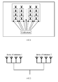
- dual polarized antennas may halve an array of antennas in width and thus lower the difficulty of engineering.
- the array of dual polarized antennas as referred to here is as illustrated in FIG. 1 , where array elements in two polarized directions are cross-arranged to thereby reduce the windward area of the array of antennas without reducing the number of antenna elements.
- FIG. 2 illustrates a schematic diagram of a multi-array antenna system with two arrays of antennas, where the arrays of antennas may be arrays of single-polarized antennas or multi-polarized antennas.
- Existing beam forming generally includes beam forming under a maximum power based criterion and beam forming under a maximum carrier to interference ratio based criterion, and weight coefficients derived in an algorithm of the former maximize the reception power at a receiver side.
- a global or local optimal solution may be derived dependent upon the varying specific implementation algorithm.
- w opt 1 is a value of w maximizing w H ⁇ R xx ⁇ w w H ⁇ w .
- a solution of the w maximizing the solution of equation (2) is unique and equal to an eigenvector corresponding to the maximum eigenvalue of the matrix method in which a global optimum solution can be derived.
- a simplified beam forming method is to search a preset set of weight vectors for a weight vector maximizing the solution of equation (2).
- Equations (3) and (5) represent two general methods for smart antenna beam forming, referred to respectively as Eigenvalue Based Beamforming (hereinafter referred to as an EBB algorithm) and Grid of Beamforming (hereinafter referred to as an GOB algorithm) .
- EBB algorithm Eigenvalue Based Beamforming
- GOB algorithm Grid of Beamforming
- All of the existing beam forming methods are applicable only to a single array of antennas with a small spacing.
- phase relationships between the arrays are not determined depending on an incident angle, therefore the existing grid of beamforming algorithm is inapplicable, and the eigenvalue based beamforming is also problematic.
- US 2005/0128983 A1 discloses a method grouping multiple transmission antennas by a base station in a mobile communication system which includes the multiple transmission antennas and multiple reception antennas, which further discloses: when a transmitter has Nt number of transmission antennas and a receiver has Nr number of reception antennas, Nt is larger than Nr in a forward link environment, the transmission antennas are classified into Nr number of groups using channel covariance so as to maximize the communication capacity of the transmitter; the channel covariance matrix is a channel value estimated by the receiver; and after the maximum eigenvalues of the sub-matrixes 'Rii' are respectively calculated, the transmission antennas are grouped so that a sum of the calculated maximum eigenvalues may be determined.
- US 2006/0234751 A1 and XP001133066 disclose both the water-filling method, in which lower
- embodiments of the invention provide a beam forming method and a device applicable to a multi-array antenna system.
- Embodiments of the invention provide a beam forming method applicable to a multi-array antenna system, as defined in claims 1 to 6.
- inventions further provide a beam forming device applicable to a multi-array antenna system, as defined in claims 7 and 8.
- a first example which provides a beam forming method, is based upon the traditional eigenvalue based beamforming algorithm and eliminates the unbalanced transmission power of antennas (an array of antennas) due to asymmetry of uplink and downlink channels and a beam forming gain loss due to limited power in the application of the traditional eigenvalue based beamforming algorithm to a multi-array antenna system.
- the specific operations 11 to 14 of the first example are as illustrated in FIG. 3 .
- a spatial cross correlation matrix R of a joint channel of all arrays of antenna is derived from h ka n , and an eigenvector w ebb corresponding to the maximum eigenvalue of R is derived as a forming vector.
- R is derived from h ka n with equations (7), (8) and (9) for the purpose of illustrating a solution of the present example, and alternatively the spatial cross correlation matrix R of the joint channel of all arrays of antennas can be derived from h ka n in other methods, which are well known to those skilled in the art and detailed description of which is omitted here.
- w ebb is transformed mainly because arrays are independent of each other. Due to the independency of the arrays, transmission power is unbalanced among the arrays as a result of beam forming based transmission based on w ebb , for example, some of the arrays have high transmission power while the remaining arrays have low transmission power. Meanwhile, due to the inconsistence between uplink and downlink channels, when beam forming is performed for the downlink by using the ratio of power received over the uplink, the allocation of power is suboptimum, and power limitation may also arise when some of the antenna elements reach the maximum transmission power. w ebb may be transformed in two ways typically.
- w ebb may be transformed per array.
- the transformation per array refers to transformation of each antenna array as a whole.
- w n is transformed with its amplitude changed while its phase relationship remaining unchanged. Further, the ratio of transmission power of each antenna is maintained within the same array. For example, transmission power of 6 watts is allocated to four antenna elements in the same untransformed array and the ratio of their transmission power is 2:2:1:1 (that is, 2 watts for two of the antennas respectively and 1 watt for the remaining two antennas respectively). Although transmission power of 9 watts may be allocated to the four antenna elements in the transformed array, the ratio of their transmission power is still 2:2:1:1 (that is, 3 watts for two of the antennas respectively and 1.5 watt for the remaining two antennas respectively).
- w n when the power allocated to an antenna element in an array according to w n exceeds the maximum transmission power of the antenna element, it is possible to limit the transmission power of the antenna element to its maximum transmission power by the transformation while reallocating the power allocated according to w n minus the transmission power of the antenna element to an antenna element of other array.
- w n is also transformed with its amplitude changed while its phase relationship remaining unchanged.
- the reallocation may be performed in a maximum ratio principle, for example, if the power allocated to an antenna element in an array according to w n exceeds the transmission power of the antenna element by 1 watt, and an antenna element of other array is allocated with power less than its maximum transmission power by 0.8 watts, then power of 0.8 watts from the power of 1 watt is reallocated to the antenna element of the other array, and the remaining power of 0.2 watts is reallocated alike.
- the reallocation may be performed in an equal ratio principle, for example, if the power allocated to an antenna element in an array according to w n exceeds the transmission power of the antenna element by 1 watt, and there are four antenna elements in total in other array, then power of 0.25 watts from the power of 1 watt is reallocated to each of the four antenna elements respectively while ensuring that the transmission power of each of the four antenna elements does not exceed the maximum transmission power thereof.
- w ebb may be transformed per antenna.
- the transformation per antenna refers to separate transformation of each antenna element.
- w n is transformed with its amplitude changed while its phase relationship remaining unchanged.
- w n when the power allocated to an antenna element in an array according to w n exceeds the maximum transmission power of the antenna element, it is possible to limit the transmission power of the antenna element to its maximum transmission power by the transformation while reallocating the power allocated according to w n minus the transmission power of the antenna element to an antenna element of other array.
- w n is also transformed with its amplitude changed while its phase relationship remaining unchanged.
- the reallocation may be performed in a maximum or equal ratio principle while ensuring that the transmission power of each antenna element does not exceed the maximum transmission power thereof.
- Operation 14 beam forming based transmission is performed using the forming vector ⁇ n or ⁇ n ( k a ) obtained from the transformation as illustrated in FIG. 4 .
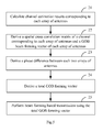
- a first embodiment of the invention relates to a beam forming method and is based upon the grid of beamforming method in the prior art.
- the traditional grid of beamforming method is not applicable if arrays are of a little correlation to each other, because a phase relationship between the arrays is not fixed for a specific incident angle. That is, no array response vector can be constructed jointly for a plurality of arrays, but the grid of beamforming algorithm can still be adopted in each array to derive its corresponding forming vector, and here a phase relationship between each two arrays is calculated in a method plurality of arrays.
- the implementation operations 21-25 are as follows.
- Operation 21 a channel estimation result corresponding to each array of antennas is calculated as in the operation 11 in the first example.
- Operation 23 a phase difference between each two arrays of antennas is derived from w gob n .
- a spatial cross correlation matrix of a joint channel of all arrays of antennas is derived.
- An eigenvector corresponding to the maximum eigenvalue of the spatial cross correlation matrix is derived.
- the derived forming vector is represented as w ebb , where,
- arg(•) represents an operation of deriving a complex phase angle.
- Operation 25 beam forming based transmission is performed by using the total GOB forming vector w gob as illustrated in FIG. 4 .
- a further embodiment of the invention relates to a beam forming method in which it is possible to switch between the foregoing two solutions adaptively in practice.
- the beam forming algorithms according to the invention have been practice, joint beam forming of plural of arrays and separate beam forming of each array with a diversity transmission algorithm can be switched in view of a specific channel environment.
- a second embodiment of the invention relates to a beam forming device applicable to a multi-array antenna system, which is structured as illustrated in FIG. 6 and includes:
- the transformation module 34 further includes:
- the device further includes:
- a further embodiment of the invention relates to a beam forming device, related to the method described in the first embodiment, applicable to a multi-array antenna system, which is structured as illustrated in FIG. 7 and includes:
- a third embodiment of the invention relates to a beam forming device applicable to a multi-array antenna system, which is structured as illustrated in FIG. 8 and includes:
Landscapes
- Engineering & Computer Science (AREA)
- Computer Networks & Wireless Communication (AREA)
- Signal Processing (AREA)
- Variable-Direction Aerials And Aerial Arrays (AREA)
- Radio Transmission System (AREA)
Description
- The present invention relates to the field of communications and particularly to a beam forming method and device.
- As mobile communication technologies develop, an array of antennas has been applied in numerous systems for an improved capacity of the systems. Accompanying this, however, and along with the development of the society, people pay increasing attention to surroundings and their own health while enjoying the convenience resulting from mobile communications, and also the electromagnetic environment has gradually become a sensitive issue on which people focus. In order to attain a sufficient gain, typically 6 to 8 antennas are required to be arranged at an interval into a traditional array of antennas. The traditional array of antennas is much larger in size than an existing single antenna, and from the perspective of engineering, the traditional array of antennas also brings more demanding to its construction due to its large windward area.
- In order to overcome the foregoing drawbacks, it will be a trend of future development to adopt an array of dual polarized antennas. The use of dual polarized antennas may halve an array of antennas in width and thus lower the difficulty of engineering. The array of dual polarized antennas as referred to here is as illustrated in
FIG. 1 , where array elements in two polarized directions are cross-arranged to thereby reduce the windward area of the array of antennas without reducing the number of antenna elements. - Moreover, it is possible in a subsequent evolved system to adopt an antenna system with arrays spaced at a distance from each other to thereby form a multi-array system. With the multi-array system, the arrays of antennas are very independent of each other to thereby offer possible smooth transition to a future Multiple-Input Multiple-output (MIMO) system.
FIG. 2 illustrates a schematic diagram of a multi-array antenna system with two arrays of antennas, where the arrays of antennas may be arrays of single-polarized antennas or multi-polarized antennas. - Along with this, however, there is also a new problem occurring with the adoption of the system with arrays of antennas. For example, the adoption of dual-polarized antennas in the system results in a reduced number of arrays of antennas in each polarized direction and consequentially a widen beam of the arrays of antennas, which challenges the use of beam forming of the arrays of antennas.
- Existing beam forming generally includes beam forming under a maximum power based criterion and beam forming under a maximum carrier to interference ratio based criterion, and weight coefficients derived in an algorithm of the former maximize the reception power at a receiver side. However, a global or local optimal solution may be derived dependent upon the varying specific implementation algorithm. For example, in the case of an smart antenna with N antenna elements, if a vector of a received multi-antenna signal is represented as x, where, x = [x 1, x 2, ···, xN ], and a vector of weight coefficients for beam forming is represented as w, where, w = [w 1, w 2, ···, wN ], then the received signal after beam forming may be represented as y, where,

- The power of the received signal after beam forming may be represented as p, where,

- Where (•)* represents conjugation of a complex (or a complex vector), (•) H represents conjugated transposition of a vector (or a matrix), and (•) T represents transposition of a vector (or a matrix). An object of the maximum power based criterion is to search for a vector of weights w to maximize the solution of equation (2).

- In equation (3), w opt1 is a value of w maximizing

- A simplified beam forming method is to search a preset set of weight vectors for a weight vector maximizing the solution of equation (2). For example, in a method taking array response vectors spaced at angles as the preset set of weight vectors, a space to be scanned is divided at angles of Φ, where, Φ = {ϕ1,ϕ2,···,ϕ L }, and an array response vector in each direction is for example represented as a(ϕ l ), l = 1,···, L (an array response vector refers to relative amplitude and phase magnitudes of an electromagnetic signal from one of the directions over an array of antennas as well known to those skilled in the art). Then after beam forming with the array response vectors, the power of the received signal may be represented as pl , where,

- Then an angle maximizing the solution of equation (4) may be obtained as w opt2, where,

- Equations (3) and (5) represent two general methods for smart antenna beam forming, referred to respectively as Eigenvalue Based Beamforming (hereinafter referred to as an EBB algorithm) and Grid of Beamforming (hereinafter referred to as an GOB algorithm) .
- All of the existing beam forming methods are applicable only to a single array of antennas with a small spacing. In the case of an antenna system with antenna arrays which tend to be very independent of each other, phase relationships between the arrays are not determined depending on an incident angle, therefore the existing grid of beamforming algorithm is inapplicable, and the eigenvalue based beamforming is also problematic. For example, in the case of a high speed, temporal correlation of a channel may be weaken due to fast fading of the channel, and in the implementation, a time delay is necessarily present with the beam forming, thus resulting in consequent asymmetry between uplink and downlink channels and implementation, there is an upper limit of antenna transmission power, and when the arrays of antennas are very independent of each other, signals received over the arrays tend to be considerably unbalanced, thus resulting in greatly unbalanced allocation of power for downlink transmission, so that a part of the antennas reach the maximum transmission power while the transmission power of the remaining antennas is likely still low, thus resulting in limited power and a loss of beam forming.
- As can be apparent from the foregoing analysis, the traditional beam forming methods fail to significantly optimize the performance of a multi-array system due to the independency between arrays in the system.
US 2005/0128983 A1 discloses a method grouping multiple transmission antennas by a base station in a mobile communication system which includes the multiple transmission antennas and multiple reception antennas, which further discloses: when a transmitter has Nt number of transmission antennas and a receiver has Nr number of reception antennas, Nt is larger than Nr in a forward link environment, the transmission antennas are classified into Nr number of groups using channel covariance so as to maximize the communication capacity of the transmitter; the channel covariance matrix is a channel value estimated by the receiver; and after the maximum eigenvalues of the sub-matrixes 'Rii' are respectively calculated, the transmission antennas are grouped so that a sum of the calculated maximum eigenvalues may be determined.
US 2006/0234751 A1 and XP001133066 disclose both the water-filling method, in which lower power loading is assigned for better channels with higher eigenvalues. - In order to address the problem that the traditional beam forming methods fail to optimize the performance of a multi-array system due to arrays in the system being independent of each other, embodiments of the invention provide a beam forming method and a device applicable to a multi-array antenna system.
- Embodiments of the invention provide a beam forming method applicable to a multi-array antenna system, as defined in
claims 1 to 6. - Also embodiments of the invention further provide a beam forming device applicable to a multi-array antenna system, as defined in claims 7 and 8.
-
FIG. 1 is a schematic diagram of an array of dual-polarized antennas in the prior art; -
FIG. 2 is a schematic diagram of a multi-array antenna system with two arrays of antennas in the prior art; -
FIG. 3 is a flow chart of a method according to an example; -
FIG. 4 is a schematic diagram of joint beam forming according to the example; -
FIG. 5 is a flow chart of a method according to a first embodiment of the invention; -
FIG. 6 is a structural diagram of a device according to a second embodiment of the invention; -
FIG. 7 is a structural diagram of a device according to the first embodiment of the invention; and -
FIG. 8 is a structural diagram of a device according to a third embodiment of the invention. - A first example, which provides a beam forming method, is based upon the traditional eigenvalue based beamforming algorithm and eliminates the unbalanced transmission power of antennas (an array of antennas) due to asymmetry of uplink and downlink channels and a beam forming gain loss due to limited power in the application of the traditional eigenvalue based beamforming algorithm to a multi-array antenna system. The
specific operations 11 to 14 of the first example are as illustrated inFIG. 3 . - Operation 11: a channel estimation result


- For example, a channel impulse response applying to a signal received over each antenna from a transmitter side to a receiver side is represented as


- Operation 12: a spatial cross correlation matrix R of a joint channel of all arrays of antenna is derived from

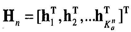
- Channel estimates of all antennas are arranged into N channel matrixes, with channel estimation results of all of the antennas in each array of antennas being arranged into a channel matrix Hn , where,

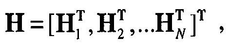
- A joint channel matrix H is derived from channel matrixes of all arrays of antennas (i.e., all of the Hn , each of which is derived from channel estimation results of all of the antennas in each array of antennas), where,

- A spatial cross correlation matrix R of a joint channel of all arrays of antennas is obtained from H derived from equation (8) as

- Here, R is derived from


- Subsequently an eigenvector w ebb corresponding to the maximum eigenvalue of the spatial cross correlation matrix R of the joint channel of all arrays of antennas is derived as the forming vector, where,

- Operation 13: the eigenvector (i.e., the forming vector) w ebb is transformed.
- Here w ebb is transformed mainly because arrays are independent of each other. Due to the independency of the arrays, transmission power is unbalanced among the arrays as a result of beam forming based transmission based on w ebb , for example, some of the arrays have high transmission power while the remaining arrays have low transmission power. Meanwhile, due to the inconsistence between uplink and downlink channels, when beam forming is performed for the downlink by using the ratio of power received over the uplink, the allocation of power is suboptimum, and power limitation may also arise when some of the antenna elements reach the maximum transmission power. w ebb may be transformed in two ways typically.
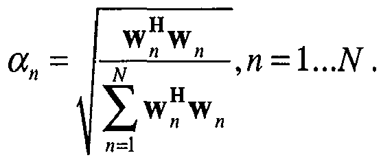
- w ebb may be transformed per array. The transformation per array refers to transformation of each antenna array as a whole. w n , which represents a forming vector corresponding to the n th array, may be derived from w ebb in the following transformation equation, where w n, n =1...N:

- Here w n is transformed with its amplitude changed while its phase relationship remaining unchanged. Further, the ratio of transmission power of each antenna is maintained within the same array. For example, transmission power of 6 watts is allocated to four antenna elements in the same untransformed array and the ratio of their transmission power is 2:2:1:1 (that is, 2 watts for two of the antennas respectively and 1 watt for the remaining two antennas respectively). Although transmission power of 9 watts may be allocated to the four antenna elements in the transformed array, the ratio of their transmission power is still 2:2:1:1 (that is, 3 watts for two of the antennas respectively and 1.5 watt for the remaining two antennas respectively). The transformation coefficient may derived as:

- Moreover, when the power allocated to an antenna element in an array according to w n exceeds the maximum transmission power of the antenna element, it is possible to limit the transmission power of the antenna element to its maximum transmission power by the transformation while reallocating the power allocated according to w n minus the transmission power of the antenna element to an antenna element of other array. Here, w n is also transformed with its amplitude changed while its phase relationship remaining unchanged. The reallocation may be performed in a maximum ratio principle, for example, if the power allocated to an antenna element in an array according to w n exceeds the transmission power of the antenna element by 1 watt, and an antenna element of other array is allocated with power less than its maximum transmission power by 0.8 watts, then power of 0.8 watts from the power of 1 watt is reallocated to the antenna element of the other array, and the remaining power of 0.2 watts is reallocated alike. Alternatively, the reallocation may be performed in an equal ratio principle, for example, if the power allocated to an antenna element in an array according to w n exceeds the transmission power of the antenna element by 1 watt, and there are four antenna elements in total in other array, then power of 0.25 watts from the power of 1 watt is reallocated to each of the four antenna elements respectively while ensuring that the transmission power of each of the four antenna elements does not exceed the maximum transmission power thereof.
- w ebb may be transformed per antenna. The transformation per antenna refers to separate transformation of each antenna element. A forming vector


- Here w n is transformed with its amplitude changed while its phase relationship remaining unchanged. The transformation coefficient may be derived as

- Moreover, when the power allocated to an antenna element in an array according to w n exceeds the maximum transmission power of the antenna element, it is possible to limit the transmission power of the antenna element to its maximum transmission power by the transformation while reallocating the power allocated according to w n minus the transmission power of the antenna element to an antenna element of other array. Here, w n is also transformed with its amplitude changed while its phase relationship remaining unchanged. The reallocation may be performed in a maximum or equal ratio principle while ensuring that the transmission power of each antenna element does not exceed the maximum transmission power thereof.
- Operation 14: beam forming based transmission is performed using the forming vector ŵ n or ŵ n (ka ) obtained from the transformation as illustrated in
FIG. 4 . - A first embodiment of the invention relates to a beam forming method and is based upon the grid of beamforming method in the prior art. For a system in a multi-array structure, the traditional grid of beamforming method is not applicable if arrays are of a little correlation to each other, because a phase relationship between the arrays is not fixed for a specific incident angle. That is, no array response vector can be constructed jointly for a plurality of arrays, but the grid of beamforming algorithm can still be adopted in each array to derive its corresponding forming vector, and here a phase relationship between each two arrays is calculated in a method plurality of arrays. As illustrated in
FIG. 5 , the implementation operations 21-25 are as follows. - Operation 21: a channel estimation result corresponding to each array of antennas is calculated as in the
operation 11 in the first example. - Operation 22: a spatial cross correlation matrix of a channel corresponding to all arrays of antennas is derived from the channel estimation results of all of the arrays of antennas, and a beam forming vector

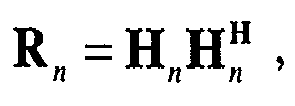
- The spatial cross correlation matrix of the channel of all of the arrays of antennas may be represented as Rn , where,

- Then the power of a signal received through beam forming by an array response vector a n (ϕ l ) of each array of antennas may be represented as


- Then an angle maximizing the solution of equation (15) is obtained for each antenna as:

- Thus a forming vector

- Operation 23: a phase difference between each two arrays of antennas is derived from

- Particularly, a spatial cross correlation matrix of a joint channel of all arrays of antennas is derived. An eigenvector corresponding to the maximum eigenvalue of the spatial cross correlation matrix is derived. In analogy to the solution in the example, the derived forming vector is represented as w ebb , where,
- Subsequently, a phase difference between each two arrays of antennas is represented as Δϕ n , where,

- Here arg(•) represents an operation of deriving a complex phase angle.
- Operation 24: a total GOB forming vector w gob is derived from the forming coefficients


- Operation 25: beam forming based transmission is performed by using the total GOB forming vector w gob as illustrated in
FIG. 4 . - A further embodiment of the invention relates to a beam forming method in which it is possible to switch between the foregoing two solutions adaptively in practice. For example, after the forming vector w ebb for beam forming in the EBB algorithm (See equation (17)) and the forming vector w gob (See equation (19)) are derived respectively in the foregoing two solutions, the power of a signal received at a terminal using either of the above two beam forming methods pgob and pebb can further be calculated from the spatial cross correlation matrix R (See equation (9)) of the joint channel of all arrays of antennas, where,


- Then determination is made so that w ebb is selected as the forming vector if pgob < pebb , otherwise w gob is selected as the forming vector.
- Moreover, the beam forming algorithms according to the invention have been practice, joint beam forming of plural of arrays and separate beam forming of each array with a diversity transmission algorithm can be switched in view of a specific channel environment.
- It shall be noted that symmetry between uplink and downlink channels of the system is assumed for joint beam forming, which necessitates elimination of inconsistency between the uplink and downlink channels due to a radio frequency channel, that is, assuming real time calibration has been implemented between the arrays of antennas to thereby eliminate inconsistency between the uplink and the downlink of the radio frequency channels.
- A second embodiment of the invention relates to a beam forming device applicable to a multi-array antenna system, which is structured as illustrated in
FIG. 6 and includes: - an

module 31 configured to derive a channel estimation result

- an
R derivation module 32 configured to derive a spatial cross correlation matrix R of a joint channel of all arrays of antennas from

module 31; - a w ebb derivation module 33 configured to derive an eigenvector w ebb corresponding to the maximum eigenvalue of R derived by the
R derivation module 32; - a
transformation module 34 configured to transform w ebb derived by the w ebb derivation module 33 by changing only its amplitude; and - a transformed beam forming based
transmission module 35 configured to perform beam forming based transmission using w ebb transformed by thetransformation module 34 as a forming vector. - The
transformation module 34 further includes: - an
array transformation module 341 configured to transform w ebb per array by changing only its amplitude. - an
antenna transformation module 342 configured to transform w ebb per antenna by changing only its amplitude. - The device further includes:
- an
allocation module 36 configured to, when the power allocated according to the forming vector of w ebb transformed by thetransformation module 34 exceeds the maximum transmission power of an antenna element, enable transmission at the maximum transmission power of the antenna element while reallocating the power allocated according to the forming vector minus the maximum transmission power of the antenna element to an antenna element of other array. - A further embodiment of the invention relates to a beam forming device, related to the method described in the first embodiment, applicable to a multi-array antenna system, which is structured as illustrated in
FIG. 7 and includes: - an

module 31 configured to derive a channel estimation result


- an R n derivation module 42 configured to derive a spatial cross correlation matrix R n of a channel corresponding to each array of antennas from


module 31; - a

derivation module 43 configured to derive a forming vector
- a Δϕ n derivation module 44 configured to derive a phase difference Δϕ n between each two arrays of antennas from


derivation module 43 and w n in claim 3, where,


derivation module 43 and Δϕ n derived by the Δϕ n derivation module 44 as
- a w gob beam forming based
transmission module 46 configured to perform beam forming based transmission using w gob derived by the w gob derivation module 45. - A third embodiment of the invention relates to a beam forming device applicable to a multi-array antenna system, which is structured as illustrated in
FIG. 8 and includes: - a pebb derivation module 51 configured to derive pebb from w ebb and R as described above as

- a pgob derivation module 52 configured to derive pgob from R and

- a
comparison module 53 configured to select the transformed w ebb as the forming vector if pgob derived by the pgob derivation module 52 is below pebb derived by the pebb derivation module 51, otherwise select w gob as the forming vector.
Claims (8)
- A beam forming method applicable to a multi-array antenna system, comprising:deriving (21) an estimation of the channel impulse response


 wherein
 deriving (22) a spatial cross correlation matrix R n of a channel corresponding to each array of antennas from
 deriving (22) antenna array weight vectors
 defining a predefined set of array response vectors a n (ϕ l ), which cover certain scanning angles ϕl , l = 1 ... L, L representing the total number of scanning angles,computing the power
 and choosing as antenna array weight vector
 deriving (12) a spatial cross correlation matrix R of a joint channel of all of the arrays of antennas from
 deriving (12) an eigenvector w ebb corresponding to the maximum eigenvalue of R, where
 deriving (23) a phase difference Δϕn between each two arrays of antennas from
 deriving (24) a total GOB antenna array weight vector w gob of all arrays of antennas from
 performing (25) beam forming based transmission using w gob .
 - The method of claim 1, further comprising:transforming (13) w ebb per array or per antenna by changing only its amplitude;deriving pebb from the transformed webb and R as
 deriving pgob from R and
 if pgob < pebb , selecting transformed w ebb as the antenna array weight vector; otherwise, selecting w gob as the antenna array weight vector.
 - The method of claim 2, wherein, transforming w ebb per array by changing only its amplitude comprises:deriving antenna array weight vectors w n of the arrays of antennas from w ebb , and transforming w n in amplitude into the antenna array weight vectors ŵ n as ŵ n = αn w n , n = 1...N, wherein,
- The method of claim 2, wherein, transforming w ebb per antenna by changing only its amplitude comprises:deriving an antenna array weight vector


- The method of claim 2, wherein, when power allocated to an antenna element according to the antenna array weight vector of transformed w ebb exceeds the maximum transmission power of the antenna element, the antenna element transmits at its maximum transmission power and the power allocated minus the maximum transmission power of the antenna element is reallocated to an antenna element of other array while ensuring that transmission power of each antenna element does not exceed the maximum transmission power thereof.
- The method of claim 5, wherein, the reallocation is performed under a maximum or equal ratio principle.
- A beam forming device applicable to a multi-array antenna system, comprising:an


 an R n derivation module (42) configured to derive from


 a
a

 and to choose as antenna array vector
 an R derivation module (32) configured to derive from


 an webb derivation module (33) configured to derive an eigenvector w ebb corresponding to the maximum eigenvalue of R, derived by the R derivation module (32), where
 a Δϕn derivation module (44) configured to derive a phase difference Δϕ n between each two arrays of antennas from
 a w gob derivation module (45) configured to derive a total GOB antenna array weight vector w gob of all of the arrays of antennas from

 a w gob beam forming based transmission module (46) configured to perform beam forming based transmission using w gob transformed by the w gob derivation module (45).
 - The device of claim 7, further comprising a transformation module (34) configured to transform w ebb per array (341) or per antenna (342) by changing only its amplitude, and the device further comprises:a pebb derivation module (51) configured to derive pebb from the transformed webb derived by the transformation module (34) and R as
 a pgob derivation module (52) configured to derive pgob from R and
 a comparison module (53) configured to select transformed w ebb as the antenna array weight vector if pgob derived by the pgob derivation module (52) is below pebb derived by the pebb derivation module (51), otherwise, select w gob as the antenna array weight vector.
Applications Claiming Priority (2)
| Application Number | Priority Date | Filing Date | Title |
|---|---|---|---|
| CN 200810056225 CN101488792B (en) | 2008-01-15 | 2008-01-15 | Wave beam shaping method and apparatus |
| PCT/CN2009/000054 WO2009092289A1 (en) | 2008-01-15 | 2009-01-15 | Beam shaping method and device |
Publications (3)
| Publication Number | Publication Date |
|---|---|
| EP2246937A1 EP2246937A1 (en) | 2010-11-03 |
| EP2246937A4 EP2246937A4 (en) | 2013-11-06 |
| EP2246937B1 true EP2246937B1 (en) | 2015-08-12 |
Family
ID=40891493
Family Applications (1)
| Application Number | Title | Priority Date | Filing Date |
|---|---|---|---|
| EP09704251.9A Active EP2246937B1 (en) | 2008-01-15 | 2009-01-15 | Beam shaping method and device |
Country Status (4)
| Country | Link |
|---|---|
| EP (1) | EP2246937B1 (en) |
| KR (1) | KR101152872B1 (en) |
| CN (1) | CN101488792B (en) |
| WO (1) | WO2009092289A1 (en) |
Cited By (2)
| Publication number | Priority date | Publication date | Assignee | Title |
|---|---|---|---|---|
| US10581504B2 (en) | 2015-12-31 | 2020-03-03 | Huawei Technologies Co., Ltd. | Beamforming method, receiver, transmitter, and system |
| WO2023086706A1 (en) * | 2021-11-12 | 2023-05-19 | Qualcomm Incorporated | Communications using dynamic beam weights |
Families Citing this family (15)
| Publication number | Priority date | Publication date | Assignee | Title |
|---|---|---|---|---|
| CN102082594B (en) * | 2009-11-30 | 2013-09-11 | 华为技术有限公司 | Beamforming method and device, and transmitting system |
| PH12013500795A1 (en) | 2010-12-17 | 2013-06-17 | Ericsson Telefon Ab L M | Beamforming method, apparatus for polarized antenna array and radio communication device and system thereof |
| JP4730677B1 (en) * | 2011-01-27 | 2011-07-20 | 日本電気株式会社 | Information processing apparatus, information processing method, and information processing program |
| CN103152085B (en) * | 2011-12-06 | 2018-02-02 | 中兴通讯股份有限公司 | The weights acquisition methods and device of three-dimensional wave beam forming |
| CN103368621B (en) * | 2012-03-26 | 2017-12-15 | 华为技术有限公司 | The processing method and equipment of signal |
| CN103427886B (en) * | 2012-05-17 | 2016-12-07 | 电信科学技术研究院 | A kind of dual-stream beamforming method and device |
| CN102959796B (en) * | 2012-08-29 | 2015-04-08 | 华为技术有限公司 | Modular antenna device and method of configuring same |
| CN105322993B (en) * | 2014-07-28 | 2018-08-10 | 普天信息技术有限公司 | A kind of broadcast wave bean shaping method |
| CN106575986B (en) * | 2014-08-13 | 2021-02-12 | 诺基亚通信公司 | Method of adjusting transmission power for eigenvalue based beamforming |
| WO2016141514A1 (en) * | 2015-03-06 | 2016-09-15 | He Xiaoxi | Beamforming method and beamforming apparatus |
| WO2017008268A1 (en) * | 2015-07-15 | 2017-01-19 | Nec Corporation | Method and apparatus for performing beamforming |
| CN109490875B (en) * | 2017-09-12 | 2022-10-14 | 启碁科技股份有限公司 | Angle estimation method and radar system |
| CN108337029A (en) * | 2017-12-29 | 2018-07-27 | 南京理工大学 | Adaptive steady kernel projected beam shaping method in secure wireless transmission |
| CN108495325A (en) * | 2018-03-28 | 2018-09-04 | 南京理工大学 | The power distribution strategies of safe rate are maximized in safe direction modulating network |
| US12212388B2 (en) * | 2023-05-26 | 2025-01-28 | Qualcomm Incorporated | Sensing based dynamic beams |
Family Cites Families (8)
| Publication number | Priority date | Publication date | Assignee | Title |
|---|---|---|---|---|
| KR100493068B1 (en) * | 2000-03-08 | 2005-06-02 | 삼성전자주식회사 | Method and apparatus for semi-blind transmit antenna array using feedback information in mobile communication system |
| KR100375826B1 (en) * | 2000-11-15 | 2003-03-15 | 한국전자통신연구원 | Weight calculation unit for forward beamforming in a direct spread CDMA base station system using an array antenna, system for forward beamforming using it and method thereof |
| KR100580762B1 (en) * | 2003-07-25 | 2006-05-15 | 엘지전자 주식회사 | Downlink beamforming method in mobile communication system |
| KR100981554B1 (en) * | 2003-11-13 | 2010-09-10 | 한국과학기술원 | In a mobile communication system having multiple transmit / receive antennas, a method of transmitting signals by grouping transmit antennas |
| US20060234751A1 (en) * | 2005-04-19 | 2006-10-19 | Samsung Electronics Co., Ltd. | Power loading method and apparatus for throughput enhancement in MIMO systems |
| CN100512052C (en) * | 2005-04-28 | 2009-07-08 | 上海原动力通信科技有限公司 | Beam shaping method for inhibiting interferes |
| CN1925362A (en) * | 2005-08-29 | 2007-03-07 | 中兴通讯股份有限公司 | Method for realizing intelligent antenna based on even linear array |
| CN100547945C (en) * | 2006-03-27 | 2009-10-07 | 普天信息技术研究院 | A method and device for downlink beamforming |
-
2008
- 2008-01-15 CN CN 200810056225 patent/CN101488792B/en active Active
-
2009
- 2009-01-15 KR KR1020107018041A patent/KR101152872B1/en active Active
- 2009-01-15 WO PCT/CN2009/000054 patent/WO2009092289A1/en not_active Ceased
- 2009-01-15 EP EP09704251.9A patent/EP2246937B1/en active Active
Non-Patent Citations (1)
| Title |
|---|
| KHALIGHI M A ET AL: "CAPACITY OF WIRELESS COMMUNICATIONS SYSTEMS EMPLOYING ANTENNA ARRAYS, A TUTORIAL STUDY", WIRELESS PERSONAL COMMUNICATIONS, SPRINGER, DORDRECHT, NL, vol. 23, no. 3, 1 December 2002 (2002-12-01), pages 321 - 352, XP001133096, ISSN: 0929-6212, DOI: 10.1023/A:1021211513679 * |
Cited By (3)
| Publication number | Priority date | Publication date | Assignee | Title |
|---|---|---|---|---|
| US10581504B2 (en) | 2015-12-31 | 2020-03-03 | Huawei Technologies Co., Ltd. | Beamforming method, receiver, transmitter, and system |
| WO2023086706A1 (en) * | 2021-11-12 | 2023-05-19 | Qualcomm Incorporated | Communications using dynamic beam weights |
| US11728869B2 (en) | 2021-11-12 | 2023-08-15 | Qualcomm Incorporated | Communications using dynamic beam weights |
Also Published As
| Publication number | Publication date |
|---|---|
| CN101488792A (en) | 2009-07-22 |
| WO2009092289A1 (en) | 2009-07-30 |
| CN101488792B (en) | 2012-10-31 |
| KR20100117605A (en) | 2010-11-03 |
| KR101152872B1 (en) | 2012-06-12 |
| EP2246937A1 (en) | 2010-11-03 |
| EP2246937A4 (en) | 2013-11-06 |
Similar Documents
| Publication | Publication Date | Title |
|---|---|---|
| EP2246937B1 (en) | Beam shaping method and device | |
| EP2777172B1 (en) | Method, apparatus and system of antenna array dynamic configuration | |
| US8571127B2 (en) | MIMO transmission with rank adaptation for multi-gigabit 60 GHz wireless | |
| Paul et al. | A novel beamspace channel estimation technique for millimeter wave massive MIMO systems | |
| US8718665B2 (en) | Method and apparatus of transmitting data in coordinated multi-cell wireless communication system | |
| US8175184B2 (en) | Method for transmitting beam forming information and a method for tracking position of a mobile station in multi input multi output system using codebook-based beam forming scheme | |
| EP3123626B1 (en) | Method of performing a hybrid beamforming in a wireless communication system and apparatus therefor | |
| US9413474B2 (en) | Efficient large-scale multiple input multiple output communications | |
| CN102624496B (en) | Precoding processing method, base station and communication system | |
| US9252864B2 (en) | Method and apparatus for fast beam-link construction in mobile communication system | |
| CN101459457B (en) | Wave beam shaping method | |
| US9160433B2 (en) | Beam codebook generation method, beam search method and related apparatuses | |
| US8750401B2 (en) | Sequential transmission multi-beamforming method with low complexity using Hadamard matrix | |
| US12255708B2 (en) | Transmission of MU-MIMO signals | |
| CN101615943B (en) | Method for estimating elevation angle of intelligent antenna multi-subarray system | |
| Wang et al. | Sensing-aided hybrid precoding for efficient terahertz wideband communications in multiuser high-data-rate IoT | |
| EP3185440B1 (en) | Doa-bf weight estimation method and device for dual-polarization antenna system | |
| CN104639220B (en) | A kind of signal receiving/transmission device and method using smart antenna | |
| KR20090043174A (en) | Transmission data generation method using precoding, transmission data generation method, generated transmission data reception method, and transmission device | |
| CN102223168B (en) | Combined transmit beamforming method based on array antenna and MIMO | |
| Jha et al. | Optimizing Synchronization Signal Block Transmissions for Sum-Rate Maximization in Sub-Connected Hybrid Beamforming Systems | |
| Elnoubi et al. | Minimum bit error rate beamforming combined with space-time block coding | |
| Li et al. | Probing Power and Minimum Rate Maximization for RIS-Aided ISAC System | |
| Torcolacci et al. | Scalable RIS-Aided Beamforming Strategies for Near-Field MU-MISO via Multi-Antenna Feeder | |
| Gaya et al. | Modeling, calculating and capacity enhancement of a Rayleigh fading MIMO channel |
Legal Events
| Date | Code | Title | Description |
|---|---|---|---|
| PUAI | Public reference made under article 153(3) epc to a published international application that has entered the european phase |
Free format text: ORIGINAL CODE: 0009012 |
|
| 17P | Request for examination filed |
Effective date: 20100812 |
|
| AK | Designated contracting states |
Kind code of ref document: A1 Designated state(s): AT BE BG CH CY CZ DE DK EE ES FI FR GB GR HR HU IE IS IT LI LT LU LV MC MK MT NL NO PL PT RO SE SI SK TR |
|
| AX | Request for extension of the european patent |
Extension state: AL BA RS |
|
| DAX | Request for extension of the european patent (deleted) | ||
| RAP1 | Party data changed (applicant data changed or rights of an application transferred) |
Owner name: CHINA ACADEMY OF TELECOMMUNICATIONS TECHNOLOGY |
|
| A4 | Supplementary search report drawn up and despatched |
Effective date: 20131004 |
|
| RIC1 | Information provided on ipc code assigned before grant |
Ipc: H04W 52/42 20090101ALI20130927BHEP Ipc: H04B 7/08 20060101ALI20130927BHEP Ipc: H01Q 21/29 20060101AFI20130927BHEP Ipc: H04B 7/04 20060101ALI20130927BHEP Ipc: H01Q 3/26 20060101ALI20130927BHEP Ipc: H04B 7/06 20060101ALI20130927BHEP |
|
| 17Q | First examination report despatched |
Effective date: 20140610 |
|
| GRAP | Despatch of communication of intention to grant a patent |
Free format text: ORIGINAL CODE: EPIDOSNIGR1 |
|
| RIC1 | Information provided on ipc code assigned before grant |
Ipc: H01Q 3/26 20060101AFI20150112BHEP Ipc: H04W 52/42 20090101ALN20150112BHEP Ipc: H04B 7/10 20060101ALN20150112BHEP Ipc: H04B 7/04 20060101ALI20150112BHEP Ipc: H04B 7/06 20060101ALN20150112BHEP |
|
| INTG | Intention to grant announced |
Effective date: 20150123 |
|
| REG | Reference to a national code |
Ref country code: DE Ref legal event code: R079 Ref document number: 602009032792 Country of ref document: DE Free format text: PREVIOUS MAIN CLASS: H01Q0021290000 Ipc: H01Q0003260000 |
|
| GRAP | Despatch of communication of intention to grant a patent |
Free format text: ORIGINAL CODE: EPIDOSNIGR1 |
|
| GRAS | Grant fee paid |
Free format text: ORIGINAL CODE: EPIDOSNIGR3 |
|
| RIC1 | Information provided on ipc code assigned before grant |
Ipc: H04B 7/10 20060101ALN20150604BHEP Ipc: H04W 52/42 20090101ALN20150604BHEP Ipc: H01Q 3/26 20060101AFI20150604BHEP Ipc: H04B 7/04 20060101ALI20150604BHEP Ipc: H04B 7/06 20060101ALN20150604BHEP |
|
| GRAA | (expected) grant |
Free format text: ORIGINAL CODE: 0009210 |
|
| INTG | Intention to grant announced |
Effective date: 20150615 |
|
| AK | Designated contracting states |
Kind code of ref document: B1 Designated state(s): AT BE BG CH CY CZ DE DK EE ES FI FR GB GR HR HU IE IS IT LI LT LU LV MC MK MT NL NO PL PT RO SE SI SK TR |
|
| REG | Reference to a national code |
Ref country code: GB Ref legal event code: FG4D |
|
| REG | Reference to a national code |
Ref country code: CH Ref legal event code: EP |
|
| REG | Reference to a national code |
Ref country code: AT Ref legal event code: REF Ref document number: 742864 Country of ref document: AT Kind code of ref document: T Effective date: 20150815 |
|
| REG | Reference to a national code |
Ref country code: IE Ref legal event code: FG4D |
|
| REG | Reference to a national code |
Ref country code: DE Ref legal event code: R096 Ref document number: 602009032792 Country of ref document: DE |
|
| REG | Reference to a national code |
Ref country code: LT Ref legal event code: MG4D |
|
| REG | Reference to a national code |
Ref country code: AT Ref legal event code: MK05 Ref document number: 742864 Country of ref document: AT Kind code of ref document: T Effective date: 20150812 |
|
| REG | Reference to a national code |
Ref country code: NL Ref legal event code: MP Effective date: 20150812 |
|
| PG25 | Lapsed in a contracting state [announced via postgrant information from national office to epo] |
Ref country code: LV Free format text: LAPSE BECAUSE OF FAILURE TO SUBMIT A TRANSLATION OF THE DESCRIPTION OR TO PAY THE FEE WITHIN THE PRESCRIBED TIME-LIMIT Effective date: 20150812 Ref country code: LT Free format text: LAPSE BECAUSE OF FAILURE TO SUBMIT A TRANSLATION OF THE DESCRIPTION OR TO PAY THE FEE WITHIN THE PRESCRIBED TIME-LIMIT Effective date: 20150812 Ref country code: GR Free format text: LAPSE BECAUSE OF FAILURE TO SUBMIT A TRANSLATION OF THE DESCRIPTION OR TO PAY THE FEE WITHIN THE PRESCRIBED TIME-LIMIT Effective date: 20151113 Ref country code: FI Free format text: LAPSE BECAUSE OF FAILURE TO SUBMIT A TRANSLATION OF THE DESCRIPTION OR TO PAY THE FEE WITHIN THE PRESCRIBED TIME-LIMIT Effective date: 20150812 Ref country code: NO Free format text: LAPSE BECAUSE OF FAILURE TO SUBMIT A TRANSLATION OF THE DESCRIPTION OR TO PAY THE FEE WITHIN THE PRESCRIBED TIME-LIMIT Effective date: 20151112 |
|
| REG | Reference to a national code |
Ref country code: FR Ref legal event code: PLFP Year of fee payment: 8 |
|
| PG25 | Lapsed in a contracting state [announced via postgrant information from national office to epo] |
Ref country code: SE Free format text: LAPSE BECAUSE OF FAILURE TO SUBMIT A TRANSLATION OF THE DESCRIPTION OR TO PAY THE FEE WITHIN THE PRESCRIBED TIME-LIMIT Effective date: 20150812 Ref country code: AT Free format text: LAPSE BECAUSE OF FAILURE TO SUBMIT A TRANSLATION OF THE DESCRIPTION OR TO PAY THE FEE WITHIN THE PRESCRIBED TIME-LIMIT Effective date: 20150812 Ref country code: HR Free format text: LAPSE BECAUSE OF FAILURE TO SUBMIT A TRANSLATION OF THE DESCRIPTION OR TO PAY THE FEE WITHIN THE PRESCRIBED TIME-LIMIT Effective date: 20150812 Ref country code: PL Free format text: LAPSE BECAUSE OF FAILURE TO SUBMIT A TRANSLATION OF THE DESCRIPTION OR TO PAY THE FEE WITHIN THE PRESCRIBED TIME-LIMIT Effective date: 20150812 Ref country code: PT Free format text: LAPSE BECAUSE OF FAILURE TO SUBMIT A TRANSLATION OF THE DESCRIPTION OR TO PAY THE FEE WITHIN THE PRESCRIBED TIME-LIMIT Effective date: 20151214 Ref country code: IS Free format text: LAPSE BECAUSE OF FAILURE TO SUBMIT A TRANSLATION OF THE DESCRIPTION OR TO PAY THE FEE WITHIN THE PRESCRIBED TIME-LIMIT Effective date: 20151212 Ref country code: ES Free format text: LAPSE BECAUSE OF FAILURE TO SUBMIT A TRANSLATION OF THE DESCRIPTION OR TO PAY THE FEE WITHIN THE PRESCRIBED TIME-LIMIT Effective date: 20150812 |
|
| PG25 | Lapsed in a contracting state [announced via postgrant information from national office to epo] |
Ref country code: NL Free format text: LAPSE BECAUSE OF FAILURE TO SUBMIT A TRANSLATION OF THE DESCRIPTION OR TO PAY THE FEE WITHIN THE PRESCRIBED TIME-LIMIT Effective date: 20150812 |
|
| PG25 | Lapsed in a contracting state [announced via postgrant information from national office to epo] |
Ref country code: EE Free format text: LAPSE BECAUSE OF FAILURE TO SUBMIT A TRANSLATION OF THE DESCRIPTION OR TO PAY THE FEE WITHIN THE PRESCRIBED TIME-LIMIT Effective date: 20150812 Ref country code: SK Free format text: LAPSE BECAUSE OF FAILURE TO SUBMIT A TRANSLATION OF THE DESCRIPTION OR TO PAY THE FEE WITHIN THE PRESCRIBED TIME-LIMIT Effective date: 20150812 Ref country code: CZ Free format text: LAPSE BECAUSE OF FAILURE TO SUBMIT A TRANSLATION OF THE DESCRIPTION OR TO PAY THE FEE WITHIN THE PRESCRIBED TIME-LIMIT Effective date: 20150812 Ref country code: IT Free format text: LAPSE BECAUSE OF FAILURE TO SUBMIT A TRANSLATION OF THE DESCRIPTION OR TO PAY THE FEE WITHIN THE PRESCRIBED TIME-LIMIT Effective date: 20150812 Ref country code: DK Free format text: LAPSE BECAUSE OF FAILURE TO SUBMIT A TRANSLATION OF THE DESCRIPTION OR TO PAY THE FEE WITHIN THE PRESCRIBED TIME-LIMIT Effective date: 20150812 |
|
| REG | Reference to a national code |
Ref country code: DE Ref legal event code: R097 Ref document number: 602009032792 Country of ref document: DE |
|
| PG25 | Lapsed in a contracting state [announced via postgrant information from national office to epo] |
Ref country code: RO Free format text: LAPSE BECAUSE OF FAILURE TO SUBMIT A TRANSLATION OF THE DESCRIPTION OR TO PAY THE FEE WITHIN THE PRESCRIBED TIME-LIMIT Effective date: 20150812 |
|
| PLBE | No opposition filed within time limit |
Free format text: ORIGINAL CODE: 0009261 |
|
| STAA | Information on the status of an ep patent application or granted ep patent |
Free format text: STATUS: NO OPPOSITION FILED WITHIN TIME LIMIT |
|
| 26N | No opposition filed |
Effective date: 20160513 |
|
| PG25 | Lapsed in a contracting state [announced via postgrant information from national office to epo] |
Ref country code: SI Free format text: LAPSE BECAUSE OF FAILURE TO SUBMIT A TRANSLATION OF THE DESCRIPTION OR TO PAY THE FEE WITHIN THE PRESCRIBED TIME-LIMIT Effective date: 20150812 Ref country code: LU Free format text: LAPSE BECAUSE OF FAILURE TO SUBMIT A TRANSLATION OF THE DESCRIPTION OR TO PAY THE FEE WITHIN THE PRESCRIBED TIME-LIMIT Effective date: 20160115 |
|
| REG | Reference to a national code |
Ref country code: CH Ref legal event code: PL |
|
| PG25 | Lapsed in a contracting state [announced via postgrant information from national office to epo] |
Ref country code: MC Free format text: LAPSE BECAUSE OF FAILURE TO SUBMIT A TRANSLATION OF THE DESCRIPTION OR TO PAY THE FEE WITHIN THE PRESCRIBED TIME-LIMIT Effective date: 20150812 |
|
| PG25 | Lapsed in a contracting state [announced via postgrant information from national office to epo] |
Ref country code: CH Free format text: LAPSE BECAUSE OF NON-PAYMENT OF DUE FEES Effective date: 20160131 Ref country code: LI Free format text: LAPSE BECAUSE OF NON-PAYMENT OF DUE FEES Effective date: 20160131 |
|
| REG | Reference to a national code |
Ref country code: IE Ref legal event code: MM4A |
|
| PG25 | Lapsed in a contracting state [announced via postgrant information from national office to epo] |
Ref country code: IE Free format text: LAPSE BECAUSE OF NON-PAYMENT OF DUE FEES Effective date: 20160115 |
|
| REG | Reference to a national code |
Ref country code: FR Ref legal event code: PLFP Year of fee payment: 9 |
|
| PG25 | Lapsed in a contracting state [announced via postgrant information from national office to epo] |
Ref country code: MT Free format text: LAPSE BECAUSE OF FAILURE TO SUBMIT A TRANSLATION OF THE DESCRIPTION OR TO PAY THE FEE WITHIN THE PRESCRIBED TIME-LIMIT Effective date: 20150812 |
|
| REG | Reference to a national code |
Ref country code: FR Ref legal event code: PLFP Year of fee payment: 10 |
|
| PG25 | Lapsed in a contracting state [announced via postgrant information from national office to epo] |
Ref country code: CY Free format text: LAPSE BECAUSE OF FAILURE TO SUBMIT A TRANSLATION OF THE DESCRIPTION OR TO PAY THE FEE WITHIN THE PRESCRIBED TIME-LIMIT Effective date: 20150812 Ref country code: HU Free format text: LAPSE BECAUSE OF FAILURE TO SUBMIT A TRANSLATION OF THE DESCRIPTION OR TO PAY THE FEE WITHIN THE PRESCRIBED TIME-LIMIT; INVALID AB INITIO Effective date: 20090115 |
|
| PG25 | Lapsed in a contracting state [announced via postgrant information from national office to epo] |
Ref country code: TR Free format text: LAPSE BECAUSE OF FAILURE TO SUBMIT A TRANSLATION OF THE DESCRIPTION OR TO PAY THE FEE WITHIN THE PRESCRIBED TIME-LIMIT Effective date: 20150812 Ref country code: MT Free format text: LAPSE BECAUSE OF FAILURE TO SUBMIT A TRANSLATION OF THE DESCRIPTION OR TO PAY THE FEE WITHIN THE PRESCRIBED TIME-LIMIT Effective date: 20160131 Ref country code: MK Free format text: LAPSE BECAUSE OF FAILURE TO SUBMIT A TRANSLATION OF THE DESCRIPTION OR TO PAY THE FEE WITHIN THE PRESCRIBED TIME-LIMIT Effective date: 20150812 |
|
| PG25 | Lapsed in a contracting state [announced via postgrant information from national office to epo] |
Ref country code: BG Free format text: LAPSE BECAUSE OF FAILURE TO SUBMIT A TRANSLATION OF THE DESCRIPTION OR TO PAY THE FEE WITHIN THE PRESCRIBED TIME-LIMIT Effective date: 20150812 |
|
| REG | Reference to a national code |
Ref country code: DE Ref legal event code: R081 Ref document number: 602009032792 Country of ref document: DE Owner name: DATANG MOBILE COMMUNICATIONS EQUIPMENT CO., LT, CN Free format text: FORMER OWNER: CHINA ACADEMY OF TELECOMMUNICATIONS TECHNOLOGY, BEIJING, CN |
|
| REG | Reference to a national code |
Ref country code: BE Ref legal event code: PD Owner name: DATANG MOBILE COMMUNICATIONS EQUIPMENT CO., LTD.; CN Free format text: DETAILS ASSIGNMENT: CHANGE OF OWNER(S), ASSIGNMENT; FORMER OWNER NAME: CHINA ACADEMY OF TELECOMMUNICATIONS TECHNOLOGY Effective date: 20210816 |
|
| REG | Reference to a national code |
Ref country code: GB Ref legal event code: 732E Free format text: REGISTERED BETWEEN 20211007 AND 20211013 |
|
| PGFP | Annual fee paid to national office [announced via postgrant information from national office to epo] |
Ref country code: DE Payment date: 20250121 Year of fee payment: 17 |
|
| PGFP | Annual fee paid to national office [announced via postgrant information from national office to epo] |
Ref country code: BE Payment date: 20250121 Year of fee payment: 17 |
|
| PGFP | Annual fee paid to national office [announced via postgrant information from national office to epo] |
Ref country code: FR Payment date: 20250127 Year of fee payment: 17 |
|
| PGFP | Annual fee paid to national office [announced via postgrant information from national office to epo] |
Ref country code: GB Payment date: 20250128 Year of fee payment: 17 |