EP2246655A1 - Heat exchanger - Google Patents
Heat exchanger Download PDFInfo
- Publication number
- EP2246655A1 EP2246655A1 EP08872595A EP08872595A EP2246655A1 EP 2246655 A1 EP2246655 A1 EP 2246655A1 EP 08872595 A EP08872595 A EP 08872595A EP 08872595 A EP08872595 A EP 08872595A EP 2246655 A1 EP2246655 A1 EP 2246655A1
- Authority
- EP
- European Patent Office
- Prior art keywords
- flat tubes
- header pipe
- refrigerant
- pipe
- inlet pipe
- Prior art date
- Legal status (The legal status is an assumption and is not a legal conclusion. Google has not performed a legal analysis and makes no representation as to the accuracy of the status listed.)
- Withdrawn
Links
- 239000003507 refrigerant Substances 0.000 claims abstract description 69
- 230000005540 biological transmission Effects 0.000 claims description 2
- 239000007788 liquid Substances 0.000 description 9
- 238000012986 modification Methods 0.000 description 5
- 230000004048 modification Effects 0.000 description 5
- 238000005192 partition Methods 0.000 description 5
- 238000004088 simulation Methods 0.000 description 5
- 238000003466 welding Methods 0.000 description 4
- 230000000694 effects Effects 0.000 description 3
- 229910052782 aluminium Inorganic materials 0.000 description 2
- XAGFODPZIPBFFR-UHFFFAOYSA-N aluminium Chemical compound [Al] XAGFODPZIPBFFR-UHFFFAOYSA-N 0.000 description 2
- 229910052751 metal Inorganic materials 0.000 description 2
- 239000002184 metal Substances 0.000 description 2
- 239000012071 phase Substances 0.000 description 2
- 238000004378 air conditioning Methods 0.000 description 1
- 230000008094 contradictory effect Effects 0.000 description 1
- 238000001125 extrusion Methods 0.000 description 1
- 238000003780 insertion Methods 0.000 description 1
- 230000037431 insertion Effects 0.000 description 1
- 239000007791 liquid phase Substances 0.000 description 1
- 239000000463 material Substances 0.000 description 1
- 238000005057 refrigeration Methods 0.000 description 1
Images




Classifications
-
- F—MECHANICAL ENGINEERING; LIGHTING; HEATING; WEAPONS; BLASTING
- F28—HEAT EXCHANGE IN GENERAL
- F28D—HEAT-EXCHANGE APPARATUS, NOT PROVIDED FOR IN ANOTHER SUBCLASS, IN WHICH THE HEAT-EXCHANGE MEDIA DO NOT COME INTO DIRECT CONTACT
- F28D1/00—Heat-exchange apparatus having stationary conduit assemblies for one heat-exchange medium only, the media being in contact with different sides of the conduit wall, in which the other heat-exchange medium is a large body of fluid, e.g. domestic or motor car radiators
- F28D1/02—Heat-exchange apparatus having stationary conduit assemblies for one heat-exchange medium only, the media being in contact with different sides of the conduit wall, in which the other heat-exchange medium is a large body of fluid, e.g. domestic or motor car radiators with heat-exchange conduits immersed in the body of fluid
- F28D1/04—Heat-exchange apparatus having stationary conduit assemblies for one heat-exchange medium only, the media being in contact with different sides of the conduit wall, in which the other heat-exchange medium is a large body of fluid, e.g. domestic or motor car radiators with heat-exchange conduits immersed in the body of fluid with tubular conduits
- F28D1/053—Heat-exchange apparatus having stationary conduit assemblies for one heat-exchange medium only, the media being in contact with different sides of the conduit wall, in which the other heat-exchange medium is a large body of fluid, e.g. domestic or motor car radiators with heat-exchange conduits immersed in the body of fluid with tubular conduits the conduits being straight
- F28D1/0535—Heat-exchange apparatus having stationary conduit assemblies for one heat-exchange medium only, the media being in contact with different sides of the conduit wall, in which the other heat-exchange medium is a large body of fluid, e.g. domestic or motor car radiators with heat-exchange conduits immersed in the body of fluid with tubular conduits the conduits being straight the conduits having a non-circular cross-section
- F28D1/05366—Assemblies of conduits connected to common headers, e.g. core type radiators
- F28D1/05375—Assemblies of conduits connected to common headers, e.g. core type radiators with particular pattern of flow, e.g. change of flow direction
-
- F—MECHANICAL ENGINEERING; LIGHTING; HEATING; WEAPONS; BLASTING
- F28—HEAT EXCHANGE IN GENERAL
- F28F—DETAILS OF HEAT-EXCHANGE AND HEAT-TRANSFER APPARATUS, OF GENERAL APPLICATION
- F28F9/00—Casings; Header boxes; Auxiliary supports for elements; Auxiliary members within casings
- F28F9/02—Header boxes; End plates
- F28F9/0246—Arrangements for connecting header boxes with flow lines
-
- F—MECHANICAL ENGINEERING; LIGHTING; HEATING; WEAPONS; BLASTING
- F28—HEAT EXCHANGE IN GENERAL
- F28D—HEAT-EXCHANGE APPARATUS, NOT PROVIDED FOR IN ANOTHER SUBCLASS, IN WHICH THE HEAT-EXCHANGE MEDIA DO NOT COME INTO DIRECT CONTACT
- F28D1/00—Heat-exchange apparatus having stationary conduit assemblies for one heat-exchange medium only, the media being in contact with different sides of the conduit wall, in which the other heat-exchange medium is a large body of fluid, e.g. domestic or motor car radiators
- F28D1/02—Heat-exchange apparatus having stationary conduit assemblies for one heat-exchange medium only, the media being in contact with different sides of the conduit wall, in which the other heat-exchange medium is a large body of fluid, e.g. domestic or motor car radiators with heat-exchange conduits immersed in the body of fluid
- F28D2001/0253—Particular components
- F28D2001/026—Cores
- F28D2001/028—Cores with empty spaces or with additional elements integrated into the cores
Definitions
- the present invention relates to a parallel-flow-type heat exchanger for use in air conditioning or refrigeration apparatuses.
- a parallel-flow-type heat exchanger having a plurality of flat tubes arranged vertically between an upper header pipe and a lower header pipe, with refrigerant passages formed inside the flat tubes so as to communicate with the insides of the two header pipes, is widely used in car air conditioners and the like. Examples thereof are seen in Patent Documents 1 and 2.
- Parallel-flow-type heat exchanger In the parallel-flow-type heat exchanger, leveling of flow rates of refrigerant among the flat tubes holds the key to improved heat exchanging performance.
- Parallel-flow-type heat exchangers disclosed in Patent Documents 1 and 2 achieve the leveling of the flow rates of refrigerant in the flat tubes in the following manners.
- Patent Document 2 Japan Patent No. 3133897
- Patent Document 2 JP-U-H06-14782
- Fig. 14 is a schematic vertical sectional view showing an outline of the structure of a conventional parallel-flow-type heat exchanger.
- a heat exchanger 1 is formed of horizontal lower and upper header pipes 2 and 3, respectively, that are arranged parallel in an up/down direction at an interval from each other, and a plurality of flat tubes 4 arranged vertically with a predetermined pitch between the lower and upper header pipes 2 and 3.
- the flat tubes 4 are elongate members formed by extrusion of a metal with high thermal conductivity, such as aluminum, and has, vertically formed inside them, refrigerant passages 5 for circulation of refrigerant R. Each of the refrigerant passages 5 allows insides of the lower and upper header pipes 2 and 3 to communicate with each other.
- the flat tubes 4 are fixed to the lower and upper header pipes 2 and 3 by welding. Between the flat tubes 4, corrugated fins 6 are arranged, and they are also fixed to the flat tubes 4 by welding. Like the flat tubes 4, the lower and upper header pipes 2 and 3 and the corrugated fins 6 are formed of a metal with high thermal conductivity (for example, aluminum).
- the lower header pipe 2 is located at a refrigerant inflow side, and an inlet pipe 7 is connected to one end thereof.
- the upper header pipe 3 is located at a refrigerant outflow side, and an outlet pipe 8 is connected to one end thereof.
- the inlet pipe 7 and the outlet pipe 8 are arranged concentrically with the lower header pipe 2 and the upper header pipes 3, respectively, and the refrigerant flows into the lower header pipe 2 in a horizontal direction and flows out of the upper header pipe 3 in a horizontal direction.
- the inlet and outlet pipes 7 and 8 are positioned diagonal to each other.
- a level of liquid refrigerant R inside the lower header pipe 2 has a tendency that it arises toward a dead-end portion at a right end of the lower header pipe 2, and flow rates of the refrigerant R in the flat tubes 4 are proportional to the level of the refrigerant R inside the lower header pipe 2.
- the flow rates of refrigerant in the flat tubes 4 are not leveled.
- a known means for leveling the flow rates of refrigerant in the flat tubes 4 is to provide a horizontal partition plate 9 inside the lower header pipe 2 as shown in Fig. 15 , but this is not an ultimate solution.
- the inlet pipe 7 is connected to a center of the lower header pipe 2 from below and the horizontal outlet pipes 8 are connected to both ends of the upper header pipe 3, a portion of refrigerant R that flows into the flat tubes 4 that are located at a center portion of flat tube row and close to the inlet pipe 7 maintains upward kinetic energy with which it flows into the lower header pipe 2, and thus a large amount of refrigerant R flows into each of the flat tubes 4 located at the flat tube row center.
- the present invention has been made in view of the above described problems, and an object of the present invention is to provide a parallel-flow-type heat exchanger in which flow rates of refrigerant in flat tubes are leveled by a new approach that is different from conventional ones.
- a heat exchanger includes: a lower header pipe that is located at a refrigerant inflow side; an upper header pipe that is located at a refrigerant outflow side; and a plurality of flat tubes that are vertically arranged between the lower header pipe and the upper header pipe, and each of which has a refrigerant passage formed inside thereof so as to communicate with an inside of the lower header pipe and an inside of the upper header pipe.
- an inlet pipe for allowing refrigerant to flow into the lower header pipe is arranged between a pair of adjacent flat tubes that are located away from an outlet pipe for allowing the refrigerant to flow out of the upper header pipe, and the inlet pipe is connected to the lower header pipe from a higher level than a lower header pipe center.
- the inlet pipe is connected to the lower header pipe from a higher level than the lower header pipe center. Consequently, the refrigerant is reflected upward inside the lower header pipe, and as a result, kinetic energy of the refrigerant is converted into pressure, and this pressure is distributed all over inside the lower header pipe. This prevents a portion of the refrigerant having kinetic energy along an inflow direction thereof from flowing mostly into specific flat tubes, and as a result, the flow rates of refrigerant in the flat tubes 4 are leveled.
- the inlet pipe extend, between the pair of adjacent flat tubes, to a vicinity of the upper header pipe.
- the inlet pipe itself can serve to perform heat exchange, and this helps improve heat exchange efficiency.
- a wind shield be provided between the pair of adjacent flat tubes between which the inlet pipe is located.
- a heat conductive plate be provided for transmission of heat to and from the pair of adjacent flat tubes.
- the outlet pipe be provided at each end of the upper header pipe, and that the inlet pipe be located between a pair of adjacent flat tubes disposed at a center of the lower header pipe.
- refrigerant flows in via the inlet pipe and hits a center part of an inner surface of the lower header pipe from above, and this makes it easy for the refrigerant to be divided into right and left flows of refrigerant, and as a result, equal amounts of refrigerant flows into the flat tubes arranged on right and left sides of the inlet pipe.
- the first embodiment is distinctive from the conventional structure shown in Fig. 16 in disposition of an inlet pipe 7.
- the inlet pipe 7 is disposed in a position that is away from outlet pipes 8.
- the outlet pipes 8 are provided at both ends of an upper header pipe 3, and thus a central part of a lower header pipe 2 is the position that is away from the outlet pipes 8.
- the structure of the first embodiment is so far the same as the structure shown in Fig.
- the inlet pipe 7 is connected to the lower header pipe 2 not from below but from above. And, in order to prevent interference between the inlet pipe 7 and flat tubes 4, only a space between a pair of adjacent flat tubes 4 that are located in a center part of the lower header pipe 2 in a horizontal direction is made wider than spaces between other pairs of adjacent flat tubes, and the inlet pipe 7 is disposed in the wider space. On both the right and left sides of the inlet pipe 7, a same number of flat tubes 4 are arranged at regular intervals (with a predetermined pitch).
- refrigerant R in liquid state flows in via the inlet pipe 7 and is then reflected by an upward-facing inner surface of the lower header pipe 2, as a result of which kinetic energy of the refrigerant R is converted into pressure, and this pressure is distributed all over inside the lower header pipe 2.
- the inlet pipe 7 does not project from a bottom of the lower header pipe 2, other members can be placed close to a bottom of the heat exchanger 1, and this makes it possible to make an apparatus incorporating the heat exchanger 1 compact.
- the outlet pipes 8 are provided one at each end of the upper header pipe 3, and the inlet pipe 7 is disposed between the pair of adjacent flat tubes 4 that are located at a center of the lower header pipe 2, the refrigerant R flows in via the inlet pipe 7, and then hits a center part of an inner surface of the lower header pipe 2 from above, and this makes it easy for the refrigerant R to be divided into right and left flows, and as a result, equal amounts of refrigerant R flows into the flat tubes arranged on both the right and left sides of the inlet pipe 7.
- the inlet pipe 7 does not need to be connected to the lower header pipe 2 from right above.
- the inlet pipe 7 may be connected to the lower header pipe 2 at an angle in a plane that is perpendicular to an axis line of the lower header pipe 2, as long as the inlet pipe 7 is connected to the lower header pipe 2 from a higher level than a lower header pipe center (that is, in a direction above a horizontal line indicated in Fig. 2 by line segment H-H, which passes a center axis of the lower header pipe 2 in section).
- FIG. 3 and 4 A modification of the first embodiment is shown in Figs. 3 and 4 .
- a horizontal partition plate 9 that reaches both ends inside the lower header pipe 2 is inserted therein substantially at a height of a center thereof.
- Fig. 5 shows a graph of the results of simulations conducted to study the effect of the connection angle of the inlet pipe on average flow rates in flat tubes.
- fourteen flat tubes were arranged on each of the right and left sides of an inlet pipe.
- the simulations were conducted for five patterns different from one another in whether or not a partition plate was provided and/or in connection angle.
- Fig. 6 shows sectional views of the lower header tubes in the patterns (a) to (e).
- the connection angle is considered to be 0° (zero degrees) when the inlet pipe is parallel with the flat tubes (vertical state), and it is considered to be 90° (ninety degrees) when the inlet pipe forms a right angle with the flat tubes (horizontal state).
- the graph shown in Fig. 5 suggests the following tendencies. That is, in the patterns (c), (d), and (e), where no partition plate is provided, in the flat tubes positioned in a vicinity of the inlet pipe (tube positions 13 to 16), average flow rates inside the tubes increase as the connection angle of the inlet pipe increases. In other flat tubes positioned away from the inlet pipe 7 (tube positions 5 to 10, 19 to 24), average flow rates inside the tubes decrease as the connection angle of the inlet pipe increases.
- the average flow rates in all the flat tubes should ideally be equal, and in this regard, the pattern (d), where the connection angle of the inlet pipe is 30° (thirty degrees), can be said to be the best.
- a second embodiment is shown in Figs. 7 and 8 .
- the second embodiment is obtained by modifying the first embodiment as follows. That is, in the second embodiment, an inlet pipe 7 extends to a vicinity of an upper header pipe 3 in a space between a pair of adjacent flat tubes 4 flanking the inlet pipe 7. This allows the inlet pipe 7 to exchange heat with air that passes thereby, and as a result, the heat exchanger 1 can perform heat exchange with higher efficiency.
- a third embodiment is shown in Figs. 9 and 10 .
- the third embodiment is obtained by modifying the first embodiment as follows. That is, in the third embodiment, a wind shield 10 is provided between a pair of adjacent flat tubes 4 flanking the inlet pipe 7.
- the wind shield 10 shown in the figures is a rectangular flat plate with its four corners rounded and its four sides shaved off in order to prevent the fitting from being hindered by overbuilt welding between the flat tubes 4 and the lower header pipe 2 or the upper header pipe 3, or by irregularity in contours of the flat tubes 4. It is preferable that the wind shield 10 be formed of a same material as, for example, the flat tubes 4, and that the wind shield 10 be fixed by welding.
- the provision of the wind shield plate 10 prevents air from passing through a space between the pair of adjacent flat tubes 4 disposed with an interval wide enough to accommodate the inlet pipe 7. In this case, it is only at gaps along the flat tubes 4 formed by shaving off the wind shield 10 that air is allowed to pass through the space between the pair of adjacent flat tubes 4 disposed with an interval wide enough to accommodate the inlet pipe 7, and thus only a very limited amount of air flows through the space. As a result, the amount of air that flows idly through the heat exchanger 1 without exchanging heat with the flat tubes 4 is reduced, and thus heat exchange efficiency is improved.
- gaps as those formed by shaving off the wind shield 10 are not necessarily indispensable, and instead, the space between the pair of adjacent flat tubes 4 disposed with an interval wide enough to accommodate the inlet pipe 7 may be completely blocked by the wind shield 10.
- the shielding plate 10 may have a horizontal section of an arch shape that is convex to windward. This allows wind to flow smoothly along a surface of the wind shield 10, and thus air-flow resistance is reduced. As a result, heat exchange efficiency is improved.
- a fourth embodiment is shown in Figs. 11 and 12 .
- the fourth embodiment is obtained by modifying the first embodiment as follows. That is, in the fourth embodiment, a heat conductive plate 11 is provided between a pair of adjacent flat tubes 4 flanking an inlet pipe 7 such that the heat conductive plate 11 exchanges heat with the pair of adjacent flat tubes 4.
- the heat conductive plate 11 shown in the figure is formed of wide corrugated fins.
- the fifth embodiment is shown in Fig. 13 .
- only a right end of an upper header pipe 3 is provided with an outlet pipe 8.
- An inlet pipe 7 is disposed in a position apart from the outlet pipe 8, that is, between a pair of adjacent flat tubes 4 located close to a left end of a lower header pipe 2.
- the inlet pipe 7 extends to a vicinity of the upper header pipe 3.
- refrigerant R in liquid state flows in via the inlet pipe 7, and is then reflected by an upward-facing inner surface of the lower header pipe 2, as a result of which kinetic energy of the refrigerant R is converted into pressure, and this pressure is distributed all over inside the lower header pipe 2.
- the inlet pipe 7 does not project from the bottom of the lower header pipe 2, other members can be placed close to the bottom of the heat exchanger 1, and this makes it possible to make an apparatus incorporating the heat exchanger 1 compact.
- the third embodiment may be combined with the second embodiment. That is, the structure may be such that the inlet pipe 7 extends to a vicinity of the upper header pipe 3 between a pair of adjacent flat tubes 4 flanking the inlet pipe 7, and the wind shield 10 is provided between the pair of adjacent flat tubes 4.
- the second embodiment and the fourth embodiment heat conductive plate
- the present invention can be practiced with any combination of the embodiments as long as a structure resulting from the combination is not contradictory in nature.
- the present invention can be widely applied to parallel-flow type heat exchangers.
Landscapes
- Engineering & Computer Science (AREA)
- Physics & Mathematics (AREA)
- Thermal Sciences (AREA)
- Mechanical Engineering (AREA)
- General Engineering & Computer Science (AREA)
- Heat-Exchange Devices With Radiators And Conduit Assemblies (AREA)
- Details Of Heat-Exchange And Heat-Transfer (AREA)
Abstract
Description
- The present invention relates to a parallel-flow-type heat exchanger for use in air conditioning or refrigeration apparatuses.
- A parallel-flow-type heat exchanger having a plurality of flat tubes arranged vertically between an upper header pipe and a lower header pipe, with refrigerant passages formed inside the flat tubes so as to communicate with the insides of the two header pipes, is widely used in car air conditioners and the like. Examples thereof are seen in
Patent Documents - In the parallel-flow-type heat exchanger, leveling of flow rates of refrigerant among the flat tubes holds the key to improved heat exchanging performance. Parallel-flow-type heat exchangers disclosed in
Patent Documents - In a heat exchanger disclosed in
Patent Document 1, one end of each of heat exchanger tubes (flat tubes) that is inserted into a refrigerant inflow vessel (a lower header pipe) to be connected thereto is formed to be tilted with respect to a direction in which refrigerant flows. This helps eliminate negative effects associated with a heat-exchanging-tube-insertion-amount error, and as a result, liquid refrigerant is equally distributed to flow into the heat exchanger tubes. Or, one end of each of heat exchanger tubes that is to be inserted into the refrigerant inflow vessel is bent in a horizontal direction and is horizontally inserted into the refrigerant inflow vessel to be connected thereto. This helps eliminate an error of an amount of insertion of the heat exchanger tubes into liquid refrigerant, and as a result, the liquid refrigerant is equally distributed to flow into the heat exchanger tubes. - In a heat exchanger disclosed in
Patent Document 2, a collective heat-exchange medium circulation port is formed at a center of one of two header pipes, and divided heat-exchange medium circulation ports are formed at both ends of the other one of the two header pipes; thus are achieved conditions necessary for achieving appropriate distribution of the heat-exchange medium.
Patent Document 1: Japan Patent No.3133897
Patent Document 2:JP-U-H06-14782 -
Fig. 14 is a schematic vertical sectional view showing an outline of the structure of a conventional parallel-flow-type heat exchanger. Aheat exchanger 1 is formed of horizontal lower andupper header pipes flat tubes 4 arranged vertically with a predetermined pitch between the lower andupper header pipes flat tubes 4 are elongate members formed by extrusion of a metal with high thermal conductivity, such as aluminum, and has, vertically formed inside them,refrigerant passages 5 for circulation of refrigerant R. Each of therefrigerant passages 5 allows insides of the lower andupper header pipes - The
flat tubes 4 are fixed to the lower andupper header pipes flat tubes 4,corrugated fins 6 are arranged, and they are also fixed to theflat tubes 4 by welding. Like theflat tubes 4, the lower andupper header pipes corrugated fins 6 are formed of a metal with high thermal conductivity (for example, aluminum). - The
lower header pipe 2 is located at a refrigerant inflow side, and aninlet pipe 7 is connected to one end thereof. Theupper header pipe 3 is located at a refrigerant outflow side, and anoutlet pipe 8 is connected to one end thereof. Theinlet pipe 7 and theoutlet pipe 8 are arranged concentrically with thelower header pipe 2 and theupper header pipes 3, respectively, and the refrigerant flows into thelower header pipe 2 in a horizontal direction and flows out of theupper header pipe 3 in a horizontal direction. - As in the example of
Patent Document 1, the inlet andoutlet pipes inlet pipe 7, a level of liquid refrigerant R inside thelower header pipe 2 has a tendency that it arises toward a dead-end portion at a right end of thelower header pipe 2, and flow rates of the refrigerant R in theflat tubes 4 are proportional to the level of the refrigerant R inside thelower header pipe 2. As a result, the flow rates of refrigerant in theflat tubes 4 are not leveled. - A known means for leveling the flow rates of refrigerant in the
flat tubes 4 is to provide ahorizontal partition plate 9 inside thelower header pipe 2 as shown inFig. 15 , but this is not an ultimate solution. - In the case where, as in the structure of the heat exchanger disclosed in
Patent Document 2 shown inFig. 16 , theinlet pipe 7 is connected to a center of thelower header pipe 2 from below and thehorizontal outlet pipes 8 are connected to both ends of theupper header pipe 3, a portion of refrigerant R that flows into theflat tubes 4 that are located at a center portion of flat tube row and close to theinlet pipe 7 maintains upward kinetic energy with which it flows into thelower header pipe 2, and thus a large amount of refrigerant R flows into each of theflat tubes 4 located at the flat tube row center. However, a portion of the refrigerant R that reaches otherflat tubes 4 located away from the flat tube row center does not have such an upward kinetic energy, and thus only a small amount of refrigerant R flows into each of the otherflat tubes 4 located away from the flat tube row center. Thus, it is very difficult to level the flow rates of refrigerant in theflat tubes 4. Also, since theinlet pipe 7 projects downward from a lower side of thelower header pipe 2, theheat exchanger 1 needs to be held high enough for theinlet pipe 7 not to hit a member (such as a bottom plate of a housing in which theheat exchanger 1 is housed) that is located below theheat exchanger 1, and as a result, a larger setting space is necessary. - The present invention has been made in view of the above described problems, and an object of the present invention is to provide a parallel-flow-type heat exchanger in which flow rates of refrigerant in flat tubes are leveled by a new approach that is different from conventional ones.
- To achieve the above object, according to the present invention, a heat exchanger includes: a lower header pipe that is located at a refrigerant inflow side; an upper header pipe that is located at a refrigerant outflow side; and a plurality of flat tubes that are vertically arranged between the lower header pipe and the upper header pipe, and each of which has a refrigerant passage formed inside thereof so as to communicate with an inside of the lower header pipe and an inside of the upper header pipe. Here, an inlet pipe for allowing refrigerant to flow into the lower header pipe is arranged between a pair of adjacent flat tubes that are located away from an outlet pipe for allowing the refrigerant to flow out of the upper header pipe, and the inlet pipe is connected to the lower header pipe from a higher level than a lower header pipe center.
- According to this structure, with the inlet pipe and the outlet pipe arranged apart from each other in a conventional way, the inlet pipe is connected to the lower header pipe from a higher level than the lower header pipe center. Consequently, the refrigerant is reflected upward inside the lower header pipe, and as a result, kinetic energy of the refrigerant is converted into pressure, and this pressure is distributed all over inside the lower header pipe. This prevents a portion of the refrigerant having kinetic energy along an inflow direction thereof from flowing mostly into specific flat tubes, and as a result, the flow rates of refrigerant in the
flat tubes 4 are leveled. - In the heat exchanger structured as described above, it is preferable that the inlet pipe extend, between the pair of adjacent flat tubes, to a vicinity of the upper header pipe.
- With this structure, the inlet pipe itself can serve to perform heat exchange, and this helps improve heat exchange efficiency.
- In the heat exchanger structured as described above, it is preferable that a wind shield be provided between the pair of adjacent flat tubes between which the inlet pipe is located.
- With this structure, air is prevented from flowing through a space between the pair of adjacent flat tubes disposed with an interval wide enough to accommodate the inlet pipe, and this reduces an amount of air that idly flows through the heat exchanger without exchanging heat with the flat tubes, and as a result, heat exchange efficiency is improved.
- In the heat exchanger structured as described above, it is preferable that, between the pair of adjacent flat tubes between which the inlet pipe is disposed, a heat conductive plate be provided for transmission of heat to and from the pair of adjacent flat tubes.
- With this structure, heat can be exchanged between the heat conductive plate and air that flows through the space between the pair of adjacent flat tubes disposed with an interval wide enough to accommodate the inlet pipe, and this helps improve heat exchange efficiency.
- In the heat exchanger structured as described above, it is preferable that the outlet pipe be provided at each end of the upper header pipe, and that the inlet pipe be located between a pair of adjacent flat tubes disposed at a center of the lower header pipe.
- With this structure, refrigerant flows in via the inlet pipe and hits a center part of an inner surface of the lower header pipe from above, and this makes it easy for the refrigerant to be divided into right and left flows of refrigerant, and as a result, equal amounts of refrigerant flows into the flat tubes arranged on right and left sides of the inlet pipe.
- According to the present invention, by connecting an inlet pipe disposed apart from an outlet pipe to a lower header pipe from a higher level than a lower header pipe center, a portion of refrigerant having kinetic energy along an inflow direction thereof is prevented from flowing mostly into specific flat tubes, and as a result, flow rates of refrigerant in the flat tubes are leveled.
-
- [
Fig. 1 ] A schematic vertical sectional view showing an outline of the structure of a heat exchanger of a first embodiment of the present invention. - [
Fig. 2 ] A sectional view taken along line A-A inFig. 1 . - [
Fig. 3 ] A schematic vertical sectional view showing an outline of the structure of a heat exchanger of a modification of the first embodiment. - [
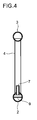
Fig. 4 ] A sectional view taken along line B-B inFig. 3 . - [
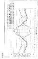
Fig. 5 ] A graph of the results of simulations conducted to study effects of the connection angle of an inlet pipe on average flow rates in flat tubes. - [
Fig. 6 ] Sectional views showing the lower header pipes used in the simulations (a) to (e) shown inFig. 5 . - [
Fig. 7 ] A schematic vertical sectional view showing an outline of the structure of a heat exchanger of a second embodiment of the invention. - [
Fig. 8 ] A sectional view taken along line C-C inFig. 7 . - [
Fig. 9 ] A schematic vertical sectional view showing an outline of the structure of a heat exchanger of a third embodiment of the invention. - [
Fig. 10 ] A sectional view taken along line D-D inFig. 9 . - [
Fig. 11 ] A schematic vertical sectional view showing an outline of the structure of a heat exchanger of a fourth embodiment of the invention. - [
Fig. 12 ] A sectional view taken along line E-E inFig. 11 . - [
Fig. 13 ] A schematic vertical sectional view showing an outline of the structure of a heat exchanger of a fifth embodiment of the invention. - [
Fig. 14 ] A schematic vertical sectional view showing an outline of the structure of a conventional heat exchanger. - [
Fig. 15 ] A schematic vertical sectional view showing an outline of the structure of another conventional heat exchanger. - [
Fig. 16 ] A schematic vertical sectional view showing an outline of the structure of a still another conventional heat exchanger. -
- 1
- heat exchanger
- 2
- lower header pipe
- 3
- upper header pipe
- 4
- flat tubes
- 5
- refrigerant passages
- 6
- corrugated fins
- 7
- inlet pipe
- 8
- outlet pipe
- 9
- partition plate
- 10
- wind shield
- 11
- heat conductive plate
- Hereinafter, a description will be given of a first embodiment of the present invention with reference to
Figs. 1 and2 . Since a structure of the first embodiment shares a lot in common with the conventional structure shown inFig. 16 , members and parts which are the same as those inFIG. 16 are given the same reference signs, and overlapping description thereof will be omitted. The first embodiment is distinctive from the conventional structure shown inFig. 16 in disposition of aninlet pipe 7. Theinlet pipe 7 is disposed in a position that is away fromoutlet pipes 8. Theoutlet pipes 8 are provided at both ends of anupper header pipe 3, and thus a central part of alower header pipe 2 is the position that is away from theoutlet pipes 8. The structure of the first embodiment is so far the same as the structure shown inFig. 16 ; however, in the present invention, theinlet pipe 7 is connected to thelower header pipe 2 not from below but from above. And, in order to prevent interference between theinlet pipe 7 andflat tubes 4, only a space between a pair of adjacentflat tubes 4 that are located in a center part of thelower header pipe 2 in a horizontal direction is made wider than spaces between other pairs of adjacent flat tubes, and theinlet pipe 7 is disposed in the wider space. On both the right and left sides of theinlet pipe 7, a same number offlat tubes 4 are arranged at regular intervals (with a predetermined pitch). - In a
heat exchanger 1 of the first embodiment, refrigerant R in liquid state flows in via theinlet pipe 7 and is then reflected by an upward-facing inner surface of thelower header pipe 2, as a result of which kinetic energy of the refrigerant R is converted into pressure, and this pressure is distributed all over inside thelower header pipe 2. This prevents refrigerant having kinetic energy along an inflow direction thereof from flowing mostly into specificflat tubes 4, and as a result, flow rates of refrigerant in theflat tubes 4 are leveled. - Also, since the
inlet pipe 7 does not project from a bottom of thelower header pipe 2, other members can be placed close to a bottom of theheat exchanger 1, and this makes it possible to make an apparatus incorporating theheat exchanger 1 compact. - Also, since the
outlet pipes 8 are provided one at each end of theupper header pipe 3, and theinlet pipe 7 is disposed between the pair of adjacentflat tubes 4 that are located at a center of thelower header pipe 2, the refrigerant R flows in via theinlet pipe 7, and then hits a center part of an inner surface of thelower header pipe 2 from above, and this makes it easy for the refrigerant R to be divided into right and left flows, and as a result, equal amounts of refrigerant R flows into the flat tubes arranged on both the right and left sides of theinlet pipe 7. - The
inlet pipe 7 does not need to be connected to thelower header pipe 2 from right above. As indicated by an imaginary line inFig. 2 , theinlet pipe 7 may be connected to thelower header pipe 2 at an angle in a plane that is perpendicular to an axis line of thelower header pipe 2, as long as theinlet pipe 7 is connected to thelower header pipe 2 from a higher level than a lower header pipe center (that is, in a direction above a horizontal line indicated inFig. 2 by line segment H-H, which passes a center axis of thelower header pipe 2 in section). - As described above, according to the present invention, it is possible to achieve leveling of the flow rates of refrigerant in flat tubes while making compact a space necessary for setting a parallel-flow type heat exchanger.
- A modification of the first embodiment is shown in
Figs. 3 and4 . In this modification, ahorizontal partition plate 9 that reaches both ends inside thelower header pipe 2 is inserted therein substantially at a height of a center thereof. As a result, even if the refrigerant R is separated into liquid and gas phases inside thelower header pipe 2, a boundary surface between the liquid and gas phases is positioned high, and thus inflow of the refrigerant R in liquid phase into theflat tubes 4 is not hindered. - Another modification as described below is also possible. That is, instead of arranging the same number of
flat tubes 4 on both of the right and left sides of theinlet pipe 7 at regular intervals, theflat tubes 4 are arranged such that lengths of the intervals among them are not uniform. Incidentally, it is preferable that the arrangement of the ununiform intervals be symmetrical with respect to theinlet pipe 7. -
Fig. 5 shows a graph of the results of simulations conducted to study the effect of the connection angle of the inlet pipe on average flow rates in flat tubes. In the simulations, fourteen flat tubes were arranged on each of the right and left sides of an inlet pipe. The simulations were conducted for five patterns different from one another in whether or not a partition plate was provided and/or in connection angle.Fig. 6 shows sectional views of the lower header tubes in the patterns (a) to (e). Incidentally, the connection angle is considered to be 0° (zero degrees) when the inlet pipe is parallel with the flat tubes (vertical state), and it is considered to be 90° (ninety degrees) when the inlet pipe forms a right angle with the flat tubes (horizontal state). - The graph shown in
Fig. 5 suggests the following tendencies. That is, in the patterns (c), (d), and (e), where no partition plate is provided, in the flat tubes positioned in a vicinity of the inlet pipe (tube positions 13 to 16), average flow rates inside the tubes increase as the connection angle of the inlet pipe increases. In other flat tubes positioned away from the inlet pipe 7 (tube positions 5 to 10, 19 to 24), average flow rates inside the tubes decrease as the connection angle of the inlet pipe increases. The average flow rates in all the flat tubes should ideally be equal, and in this regard, the pattern (d), where the connection angle of the inlet pipe is 30° (thirty degrees), can be said to be the best. - A second embodiment is shown in
Figs. 7 and8 . The second embodiment is obtained by modifying the first embodiment as follows. That is, in the second embodiment, aninlet pipe 7 extends to a vicinity of anupper header pipe 3 in a space between a pair of adjacentflat tubes 4 flanking theinlet pipe 7. This allows theinlet pipe 7 to exchange heat with air that passes thereby, and as a result, theheat exchanger 1 can perform heat exchange with higher efficiency. - A third embodiment is shown in
Figs. 9 and10 . The third embodiment is obtained by modifying the first embodiment as follows. That is, in the third embodiment, awind shield 10 is provided between a pair of adjacentflat tubes 4 flanking theinlet pipe 7. Thewind shield 10 shown in the figures is a rectangular flat plate with its four corners rounded and its four sides shaved off in order to prevent the fitting from being hindered by overbuilt welding between theflat tubes 4 and thelower header pipe 2 or theupper header pipe 3, or by irregularity in contours of theflat tubes 4. It is preferable that thewind shield 10 be formed of a same material as, for example, theflat tubes 4, and that thewind shield 10 be fixed by welding. - The provision of the
wind shield plate 10 prevents air from passing through a space between the pair of adjacentflat tubes 4 disposed with an interval wide enough to accommodate theinlet pipe 7. In this case, it is only at gaps along theflat tubes 4 formed by shaving off thewind shield 10 that air is allowed to pass through the space between the pair of adjacentflat tubes 4 disposed with an interval wide enough to accommodate theinlet pipe 7, and thus only a very limited amount of air flows through the space. As a result, the amount of air that flows idly through theheat exchanger 1 without exchanging heat with theflat tubes 4 is reduced, and thus heat exchange efficiency is improved. Incidentally, such gaps as those formed by shaving off thewind shield 10 are not necessarily indispensable, and instead, the space between the pair of adjacentflat tubes 4 disposed with an interval wide enough to accommodate theinlet pipe 7 may be completely blocked by thewind shield 10. - The shielding
plate 10 may have a horizontal section of an arch shape that is convex to windward. This allows wind to flow smoothly along a surface of thewind shield 10, and thus air-flow resistance is reduced. As a result, heat exchange efficiency is improved. - A fourth embodiment is shown in
Figs. 11 and12 . The fourth embodiment is obtained by modifying the first embodiment as follows. That is, in the fourth embodiment, a heatconductive plate 11 is provided between a pair of adjacentflat tubes 4 flanking aninlet pipe 7 such that the heatconductive plate 11 exchanges heat with the pair of adjacentflat tubes 4. The heatconductive plate 11 shown in the figure is formed of wide corrugated fins. - The provision of the heat
conductive plate 11, which can exchange heat with air passing though the space between the pair of adjacentflat tubes 4 disposed with an interval wide enough to accommodate theinlet pipe 7, helps improve heat exchange efficiency. - The fifth embodiment is shown in
Fig. 13 . In the fifth embodiment, only a right end of anupper header pipe 3 is provided with anoutlet pipe 8. Aninlet pipe 7 is disposed in a position apart from theoutlet pipe 8, that is, between a pair of adjacentflat tubes 4 located close to a left end of alower header pipe 2. Theinlet pipe 7 extends to a vicinity of theupper header pipe 3. - In a
heat exchanger 1 of the fifth embodiment, too, refrigerant R in liquid state flows in via theinlet pipe 7, and is then reflected by an upward-facing inner surface of thelower header pipe 2, as a result of which kinetic energy of the refrigerant R is converted into pressure, and this pressure is distributed all over inside thelower header pipe 2. This prevents refrigerant having kinetic energy along an inflow direction thereof from flowing mostly into specificflat tubes 4, and as a result, flow rates of refrigerant in theflat tubes 4 are leveled. - Also, since the
inlet pipe 7 does not project from the bottom of thelower header pipe 2, other members can be placed close to the bottom of theheat exchanger 1, and this makes it possible to make an apparatus incorporating theheat exchanger 1 compact. - The descriptions have been given above of the embodiments of the present invention, but the embodiments are not meant to limit the scope of the present invention, and the present invention may be practiced with various modifications without departing from the scope of the present invention. For example, the third embodiment may be combined with the second embodiment. That is, the structure may be such that the
inlet pipe 7 extends to a vicinity of theupper header pipe 3 between a pair of adjacentflat tubes 4 flanking theinlet pipe 7, and thewind shield 10 is provided between the pair of adjacentflat tubes 4. Combination of the second embodiment and the fourth embodiment (heat conductive plate) is also possible. And the present invention can be practiced with any combination of the embodiments as long as a structure resulting from the combination is not contradictory in nature. - The present invention can be widely applied to parallel-flow type heat exchangers.
Claims (5)
- A heat exchanger comprising:a lower header pipe that is located at a refrigerant inflow side;an upper header pipe that is located at a refrigerant outflow side; anda plurality of flat tubes that are vertically arranged between the lower header pipe and the upper header pipe, and each of which has a refrigerant passage formed inside thereof so as to communicate with an inside of the lower header pipe and an inside of the upper header pipe,wherein
an inlet pipe for allowing refrigerant to flow into the lower header pipe is arranged between a pair of adjacent flat tubes that are located away from an outlet pipe for allowing the refrigerant to flow out of the upper header pipe, and
the inlet pipe is connected to the lower header pipe from a higher level than a lower header pipe center. - The heat exchanger of claim 1, wherein
the inlet pipe extends, between the pair of adjacent flat tubes, to a vicinity of the upper header pipe. - The heat exchanger of claim 1, wherein
a wind shield is provided between the pair of adjacent flat tubes between which the inlet pipe is disposed. - The heat exchanger of claim 1, wherein
between the pair of adjacent flat tubes between which the inlet pipe is disposed, a heat conductive plate is provided for transmission of heat to and from the pair of adjacent flat tubes. - The heat exchanger of any one of claims 1 to 4, wherein
the outlet pipe is provided at each end of the upper header pipe, and the inlet pipe is disposed between a pair of adjacent flat tubes located at a center of the lower header pipe.
Applications Claiming Priority (2)
| Application Number | Priority Date | Filing Date | Title |
|---|---|---|---|
| JP2008036932A JP4357571B2 (en) | 2008-02-19 | 2008-02-19 | Heat exchanger |
| PCT/JP2008/066165 WO2009104295A1 (en) | 2008-02-19 | 2008-09-08 | Heat exchanger |
Publications (2)
| Publication Number | Publication Date |
|---|---|
| EP2246655A1 true EP2246655A1 (en) | 2010-11-03 |
| EP2246655A4 EP2246655A4 (en) | 2017-07-05 |
Family
ID=40985190
Family Applications (1)
| Application Number | Title | Priority Date | Filing Date |
|---|---|---|---|
| EP08872595.7A Withdrawn EP2246655A4 (en) | 2008-02-19 | 2008-09-08 | Heat exchanger |
Country Status (4)
| Country | Link |
|---|---|
| EP (1) | EP2246655A4 (en) |
| JP (1) | JP4357571B2 (en) |
| CN (1) | CN101932900B (en) |
| WO (1) | WO2009104295A1 (en) |
Families Citing this family (8)
| Publication number | Priority date | Publication date | Assignee | Title |
|---|---|---|---|---|
| CN103983126B (en) * | 2014-05-28 | 2016-08-24 | 丹佛斯微通道换热器(嘉兴)有限公司 | Heat exchanger |
| KR102202418B1 (en) * | 2015-03-19 | 2021-01-13 | 한온시스템 주식회사 | Evaporator of air conditioner for vehicle |
| JP2019219061A (en) * | 2016-09-16 | 2019-12-26 | 株式会社日立製作所 | Heat exchanger and heat pump system using the same |
| JP2019219074A (en) * | 2018-06-15 | 2019-12-26 | 東芝ライフスタイル株式会社 | refrigerator |
| CN109059584A (en) * | 2018-08-10 | 2018-12-21 | 天津大学 | A kind of unequal spacing tube bank sea water source heat pump heat exchanger |
| CN113375481A (en) * | 2021-06-25 | 2021-09-10 | 安徽普瑞普勒传热技术有限公司 | Water-cooled parallel flow heat exchanger with flat tubes in row |
| US20250244089A1 (en) * | 2022-04-14 | 2025-07-31 | Mitsubishi Electric Corporation | Heat exchanger and air-conditioning apparatus including the same |
| CN218270291U (en) * | 2022-07-01 | 2023-01-10 | 丹佛斯有限公司 | Heat exchanger |
Family Cites Families (11)
| Publication number | Priority date | Publication date | Assignee | Title |
|---|---|---|---|---|
| US4484622A (en) * | 1982-04-27 | 1984-11-27 | The Garrett Corporation | Integral header heat exchanger |
| JPH0721367B2 (en) * | 1986-06-28 | 1995-03-08 | 日本電装株式会社 | Stacked heat exchanger |
| JPH0616310Y2 (en) * | 1989-04-27 | 1994-04-27 | サンデン株式会社 | Heat exchanger |
| JPH0379994A (en) * | 1989-08-19 | 1991-04-04 | Nippondenso Co Ltd | Heat exchanger |
| JPH0614782U (en) | 1991-12-16 | 1994-02-25 | 日本軽金属株式会社 | Heat exchanger |
| JPH06273088A (en) * | 1993-03-24 | 1994-09-30 | Zexel Corp | Parallel flow heat exchanger |
| JP3133897B2 (en) | 1994-06-23 | 2001-02-13 | シャープ株式会社 | Heat exchanger |
| US5826649A (en) * | 1997-01-24 | 1998-10-27 | Modine Manufacturing Co. | Evaporator, condenser for a heat pump |
| JP2004077032A (en) * | 2002-08-20 | 2004-03-11 | Zexel Valeo Climate Control Corp | Both tank type heat exchanger |
| JP2004251556A (en) * | 2003-02-20 | 2004-09-09 | Matsushita Electric Ind Co Ltd | Heat exchanger |
| JP2006138559A (en) * | 2004-11-12 | 2006-06-01 | Calsonic Kansei Corp | Heat exchanger for vehicle |
-
2008
- 2008-02-19 JP JP2008036932A patent/JP4357571B2/en not_active Expired - Fee Related
- 2008-09-08 CN CN200880125963.7A patent/CN101932900B/en not_active Expired - Fee Related
- 2008-09-08 EP EP08872595.7A patent/EP2246655A4/en not_active Withdrawn
- 2008-09-08 WO PCT/JP2008/066165 patent/WO2009104295A1/en not_active Ceased
Non-Patent Citations (1)
| Title |
|---|
| See references of WO2009104295A1 * |
Also Published As
| Publication number | Publication date |
|---|---|
| EP2246655A4 (en) | 2017-07-05 |
| CN101932900B (en) | 2012-09-19 |
| WO2009104295A1 (en) | 2009-08-27 |
| JP2009198016A (en) | 2009-09-03 |
| JP4357571B2 (en) | 2009-11-04 |
| CN101932900A (en) | 2010-12-29 |
Similar Documents
| Publication | Publication Date | Title |
|---|---|---|
| EP2246655A1 (en) | Heat exchanger | |
| KR102255779B1 (en) | Heat exchanger and manufacturing method therefor, heat exchange module, heat exchange device and heat source unit | |
| US20090242184A1 (en) | Spiral Tube Fin Heat Exchanger | |
| CN102252558A (en) | Heat exchange device | |
| KR101499193B1 (en) | Heat exchange device | |
| WO2020062722A1 (en) | Fin and heat exchanger having same | |
| EP2770289A1 (en) | Heat exchange apparatus | |
| CN109186302B (en) | Fin and heat exchanger with same | |
| US20170045312A1 (en) | Heat exchanger comprising a core of tubes | |
| KR101243676B1 (en) | Plate-type Heat Exchanger | |
| KR101422583B1 (en) | Tube-equipped heat exchanger | |
| CN216954186U (en) | Heat exchange partition plate and counter-flow heat exchanger used for middle section position of heat exchange pipeline | |
| CN209877709U (en) | Heat exchanger | |
| KR101315648B1 (en) | Plate-type heat exchanger | |
| CN103673719A (en) | Fin of heat exchanger and heat exchanger | |
| KR20100024706A (en) | Air mixer and heat exchanger having the same | |
| CN219141578U (en) | Heat exchanger | |
| CN220912096U (en) | Baffle plate group and shell-and-tube heat exchanger | |
| US20250383167A1 (en) | Fluid distributor and heat exchanger | |
| CN216522487U (en) | Heat pump set capable of uniformly distributing air | |
| JP2009198172A (en) | Heat exchanger | |
| TR201807001T4 (en) | Heat exchanger with collection duct for evacuating a liquid phase. | |
| CN217058459U (en) | Heat exchanger capable of improving heat exchange effect | |
| CN119573425B (en) | Microchannel heat exchanger with uniform tube side flow distribution | |
| CN223179361U (en) | Cold and hot gas heat exchanger |
Legal Events
| Date | Code | Title | Description |
|---|---|---|---|
| PUAI | Public reference made under article 153(3) epc to a published international application that has entered the european phase |
Free format text: ORIGINAL CODE: 0009012 |
|
| 17P | Request for examination filed |
Effective date: 20100812 |
|
| AK | Designated contracting states |
Kind code of ref document: A1 Designated state(s): AT BE BG CH CY CZ DE DK EE ES FI FR GB GR HR HU IE IS IT LI LT LU LV MC MT NL NO PL PT RO SE SI SK TR |
|
| AX | Request for extension of the european patent |
Extension state: AL BA MK RS |
|
| DAX | Request for extension of the european patent (deleted) | ||
| RA4 | Supplementary search report drawn up and despatched (corrected) |
Effective date: 20170608 |
|
| RIC1 | Information provided on ipc code assigned before grant |
Ipc: F28D 1/053 20060101ALI20170601BHEP Ipc: F28F 9/02 20060101AFI20170601BHEP Ipc: F25B 39/02 20060101ALI20170601BHEP Ipc: F28F 9/22 20060101ALI20170601BHEP Ipc: F28D 1/02 20060101ALI20170601BHEP |
|
| GRAP | Despatch of communication of intention to grant a patent |
Free format text: ORIGINAL CODE: EPIDOSNIGR1 |
|
| STAA | Information on the status of an ep patent application or granted ep patent |
Free format text: STATUS: GRANT OF PATENT IS INTENDED |
|
| INTG | Intention to grant announced |
Effective date: 20180430 |
|
| STAA | Information on the status of an ep patent application or granted ep patent |
Free format text: STATUS: THE APPLICATION IS DEEMED TO BE WITHDRAWN |
|
| 18D | Application deemed to be withdrawn |
Effective date: 20180911 |