EP2246486B1 - Decorative cover structure for construction machine - Google Patents
Decorative cover structure for construction machine Download PDFInfo
- Publication number
- EP2246486B1 EP2246486B1 EP08872774A EP08872774A EP2246486B1 EP 2246486 B1 EP2246486 B1 EP 2246486B1 EP 08872774 A EP08872774 A EP 08872774A EP 08872774 A EP08872774 A EP 08872774A EP 2246486 B1 EP2246486 B1 EP 2246486B1
- Authority
- EP
- European Patent Office
- Prior art keywords
- tank
- dressing cover
- worker
- fuel tank
- dressing
- Prior art date
- Legal status (The legal status is an assumption and is not a legal conclusion. Google has not performed a legal analysis and makes no representation as to the accuracy of the status listed.)
- Active
Links
- 238000010276 construction Methods 0.000 title claims description 15
- 239000002828 fuel tank Substances 0.000 description 50
- 230000009194 climbing Effects 0.000 description 6
- 238000012423 maintenance Methods 0.000 description 3
- 238000009412 basement excavation Methods 0.000 description 1
- 230000004907 flux Effects 0.000 description 1
- 239000010720 hydraulic oil Substances 0.000 description 1
Images

Classifications
-
- E—FIXED CONSTRUCTIONS
- E02—HYDRAULIC ENGINEERING; FOUNDATIONS; SOIL SHIFTING
- E02F—DREDGING; SOIL-SHIFTING
- E02F9/00—Component parts of dredgers or soil-shifting machines, not restricted to one of the kinds covered by groups E02F3/00 - E02F7/00
-
- E—FIXED CONSTRUCTIONS
- E02—HYDRAULIC ENGINEERING; FOUNDATIONS; SOIL SHIFTING
- E02F—DREDGING; SOIL-SHIFTING
- E02F9/00—Component parts of dredgers or soil-shifting machines, not restricted to one of the kinds covered by groups E02F3/00 - E02F7/00
- E02F9/08—Superstructures; Supports for superstructures
- E02F9/0833—Improving access, e.g. for maintenance, steps for improving driver's access, handrails
Description
- The present invention belongs to the technical field of a dressing cover structure to be provided for covering a tank side surface in a construction machine which allows a worker to get onto and off an upper surface of a tank.
- Generally, some construction machines, such as hydraulic shovels, are configured so that a worker is allowed to get onto and off an upper surface of a tank (fuel tank or hydraulic oil tank) equipped on the construction machine. The worker can use the tank upper surface as a scaffold or walkway when performing maintenance and refueling, etc. Some construction machines have a tank side surface on a side where the worker passes to get onto and off the tank upper surface, which is covered by a dressing cover (for example, refer to
Patent Document 1,Patent Document 2 and Patent Document 3). - Patent Document 1: Japanese Published Unexamined Patent Application No.
2001-262620 - Patent Document 2: Japanese Published Unexamined Patent Application No.
2005-248618 - Patent Document 3: Japanese Published Unexamined Patent Application No.
2002-256593 claim 1. - The dressing covers of
Patent Documents
When the tank upper surface is used as a scaffold or walkway, as shown inPatent Document 1, an upper surface plate with an antiskid function is generally attached to the tank upper surface. However, as described above, the upper surface of the dressing cover is what the worker normally steps on. As a result, the upper surface of the dressing cover is also required to have an antiskid function, therefore further increasing costs. The present invention intends to solve the problems. - The present invention was made for the purpose of solving the above-described problem in view of the above-described circumstances. A first aspect of the present invention provides a dressing cover structure in a construction machine which allows a worker to get onto and off an upper surface of a tank, wherein when a dressing cover covers a side surface of the tank on a side where the worker passes to get onto and off the upper surface of the tank, an upper portion of the dressing cover is formed by an inclined surface having an inclination angle set so as not to allow the worker who gets onto and off the upper surface of the tank to step on the upper portion of the dressing cover.
A second aspect of the present invention provides the dressing cover structure in the construction machine according to the first aspect, wherein the inclined surface of the dressing cover is formed across the entire upper portion of the dressing cover except portions which are unlikely to be stepped on by the worker who gets onto and off the upper surface of the tank.
A third aspect of the present invention provides the dressing cover structure in the construction machine according to the first or second aspect, wherein the upper end position of the inclined surface of the dressing cover is lower than the upper surface of the tank.
A fourth aspect of the present invention provides the dressing cover structure in the construction machine according to the third aspect, wherein an upper surface plate with an antiskid function is attached to the upper surface of the tank, an edge portion of the upper surface plate at a side of the dressing cover is bent downward to be hung down from the upper surface of the tank, and such hung-down portion covers the side surface of the tank between the upper end of the inclined surface of the dressing cover and the upper surface of the tank. - According to the first aspect of the present invention, stepping on the upper portion of the dressing cover by a worker who gets onto and off the tank upper surface can be reliably avoided. Therefore, it becomes unnecessary to structure the dressing cover with a sufficient strength and attachment in order to withstand the stepping on by the worker. The dressing cover can thus be made light in weight and inexpensive, and does not need to have an antiskid function, which greatly contributes to cost reduction.
According to the second aspect of the present invention, stepping on the dressing cover by a worker can be prevented across the entire upper portion of the dressing cover.
According to the third aspect of the present invention, the risk of stepping on the upper end of the inclined surface by a worker's foot put on the tank upper surface can be reliably prevented.
According to the fourth aspect of the present invention, by the hung-down portion of the upper surface plate, the tank side surface between the upper end of the inclined surface of the dressing cover and the tank upper surface is covered. Therefore, although the upper end position of the inclined surface is set lower than the tank upper surface, the upper portion of the tank side surface is not exposed, and therefore an excellent external appearance can be obtained. -
-
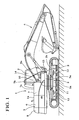
FIG. 1 is a side view of a hydraulic shovel; -
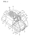
FIG. 2 is a perspective view showing the surrounding of a fuel tank; -
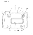
FIG. 3 is a front view of a dressing cover; -
FIG. 4A is a left side view of the dressing cover,FIG. 4B is a sectional view along X-X ofFIG. 3 , andFIG. 4C is a right side view of the dressing cover; -
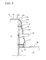
FIG. 5 is a view showing attachment of the dressing cover; and -
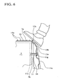
FIG. 6 is an enlarged view of a portion ofFIG. 5 . -
- 7
- fuel tank
- 7a
- upper surface of fuel tank
- 7b
- front surface of fuel tank
- 11
- dressing cover
- 11e
- inclined surface of dressing cover
- 15
- upper surface plate
- 15b
- hung-down portion of upper surface plate
- Next, an embodiment of the present invention will be described with reference to the drawings. In the drawings,
reference numeral 1 denotes a hydraulic shovel as an example of a construction machine. Thehydraulic shovel 1 includes a crawler-type lower travelingbody 2 and an upper turningbody 3 supported turnably on the lower travelingbody 2. The upper turningbody 3 includes afront work portion 4 for performing work such as excavation, a cab 5, anengine room 6 in which various devices such as an engine and a pump unit not shown are housed, afuel tank 7, acounterweight 8, and astorage box 9 for storing pail cans and tools, etc. - The
storage box 9 is disposed at the front end portion on the left side (left side as viewed from the front of the upper turningbody 3, the same applies to the following description) of the upper turningbody 3. The fuel tank (which is an example of the tank of the present invention) 7 is disposed on the rear side of thestorage box 9, with theupper surface 7a of thefuel tank 7 forming a substantially flux machine body upper surface 1a in conjunction with the upper surface of theengine room 6 and the upper surface of thecounterweight 8. When work is performed such as maintenance and refueling of the devices inside theengine room 6, theupper surface 7a of thefuel tank 7 is used as a scaffold or walkway by a worker. - On the other hand, the
upper surface 9a of thestorage box 9 is configured so as to open and close in order to store objects such as pail cans to be put in and pulled out of thestorage box 9. The height of theupper surface 9a of thestorage box 9 is designed to be lower than theupper surface 7a of thefuel tank 7. Further, to thefront surface 7b of thefuel tank 7, at a substantially intermediate height between theupper surface 7a of thefuel tank 7 and theupper surface 9a of thestorage box 9, a climbingstep 10, which a worker puts his/her foot on, is attached. A worker can put his/her foot on the climbingstep 10 and go up and down between theupper surface 9a of thestorage box 9 and theupper surface 7a of thefuel tank 7.
As described later, thefront surface 7b of thefuel tank 7 is covered by a dressingcover 11. The dressingcover 11 includes astep opening 1 If through which the climbingstep 10 penetrates. The climbingstep 10 attached to thefront surface 7b of thefuel tank 7 is provided so as to penetrate through the step opening 11f of the dressingcover 11 and project forward of the dressingcover 11. - Further, the
reference numeral 12 denotes a step attached to aframe 2a of thelower traveling body 2, thereference numeral 13 denotes a step attached to amount frame 3a of theupper turning body 3. A worker can access theupper surface 9a of thestorage box 9 from the ground by passing over the upper surfaces of thesteps reference numeral 14 is a handrail to be gripped by a worker when the worker goes up and down. One end side of thehandrail 14 is supported on the front side left end portion of themount frame 3a of theupper turning body 3, and the other end side is supported on the left side end portion of theupper surface 7a of thefuel tank 7. - Here, to the
upper surface 7a of thefuel tank 7, anupper surface plate 15 having a plurality ofantiskid protrusions 15a is attached. The front side edge portion of theupper surface plate 15 is bent downward and slightly hung down from theupper surface 7a of thefuel tank 7. At thecorner portion 15c on the upper end of the hung-downportion 15b, anantiskid protrusion 15a is also formed so as to prevent a worker from slipping even when the worker puts his/her foot on thecorner portion 15c of theupper surface plate 15. - Surface plates with an antiskid function are also attached to the upper surface of the
engine room 6 forming the machine body upper surface 1 a in conjunction with theupper surface 7a of thefuel tank 7 and theupper surface 9a of thestorage box 9 although these face plates are not shown. Accordingly, a worker is prevented from slipping when the worker gets onto and off the machine body upper surface 1a or performs work. - On the other hand, the
front surface 7b of thefuel tank 7 is a tank side surface on the side where a worker who gets onto and off theupper surface 7a of thefuel tank 7 from theupper surface 9a of thestorage box 9 passes. As described above, to the front surface, the climbingstep 10 is attached, and thefront surface 7b of thefuel tank 7 is covered by a dressingcover 11. - The dressing
cover 11 is provided for improving the external appearance by hiding weld marks, etc., on thefront surface 7b of thefuel tank 7. The dressingcover 11 includes afront surface 11a, aleft surface 11b, aright surface 11c, and alower surface 11d, and has a substantially rectangular triangle shape in a side view, and the rear surface side opposed to thefront surface 7b of thefuel tank 7 is open. - The
front surface 11a of the dressingcover 11 is inclined so as to become closer to thefront surface 7b of thefuel tank 7 toward the upper side. The upper portion of thefront surface 11a is formed by aninclined surface 11e with an inclination angle set so as not to allow a worker going up and down between theupper surface 9a of thestorage box 9 and theupper surface 7a of thefuel tank 7 to step onto the upper portion. Specifically, the upper portion of thefront surface 11a of the dressingcover 11 is formed by a sharp-pointedinclined surface 11e which becomes closer to thefront surface 7b of thefuel tank 7 toward the upper side so that a worker going up and down cannot step onto the upper portion. Theinclined surface 11e is formed across the entire upper portion of thefront surface 11a except for portions on which thehandrail 14 is disposed and which are unlikely to be stepped on by a worker (the left side end portion of the dressingcover 11 in the present embodiment). - Further, the upper end position of the
inclined surface 11e is lower than theupper surface 7a of thefuel tank 7. Accordingly, even when a worker puts his/her foot on thecorner portion 15c of theupper surface plate 15, the foot can be reliably prevented from stepping on the upper end of theinclined surface 11e (seeFIG. 6 ). - Here, as described above, the front side edge portion of the
upper surface plate 15 is bent downward and slightly hung down from theupper surface plate 7a of thefuel tank 7, and the lower end of the hung-downportion 15b is designed so as to be positioned slightly lower than the upper end position of theinclined surface 11e. Accordingly, by the hung-downportion 15b of theupper surface plate 15, the fueltank front surface 7b between the upper end of theinclined surface 11e and the fuel tankupper surface 7a is covered. - In the
front surface 11a of the dressingcover 11, as described above, the step opening 11f through which the climbingstep 10 penetrates is open, and throughholes 11g forbolts 16 for attaching the dressingcover 11 to thefront surface 7b of thefuel tank 7 are open at four positions in total. By screwing thebolts 16 inserted into the throughholes 11g from the front side of the dressingcover 11 intoscrew hole portions 7c formed in thefront surface 7b of thefuel tank 7, the dressingcover 11 can be attached to thefront surface 7b of thefuel tank 7. - In the present embodiment configured as described above, when a worker performs a work such as maintenance or refueling by getting onto the machine body upper surface 1a, the worker passes over the
upper surface 9a of thestorage box 9 disposed ahead of thefuel tank 7 and gets onto and off theupper surface 7a of thefuel tank 7. Thefront surface 7b of the fuel tank 7 (the tank side surface on the side the worker passes to get onto and off theupper surface 7a of the fuel tank 7) is covered by the dressingcover 11. The upper portion of the dressingcover 11 is formed by a sharp-pointedinclined surface 11e which becomes closer to thefront surface 7b of thefuel tank 7 toward the upper side. That is, theinclined surface 11e is used with an inclination angle set so as not to allow the worker who gets onto and off theupper surface 7a of thefuel tank 7 to step on the upper portion. - As a result, a worker who gets onto and off the
upper surface 7a of thefuel tank 7 can be reliably prevented from stepping on the upper portion of the dressingcover 11. Therefore, it is not necessary to structure the dressingcover 11 such that the dressingcover 11 withstands having a worker step on it (e.g., strength and attachment). Therefore, the dressingcover 11 can be made light in weight and inexpensive, and does not need to have an antiskid function, thus greatly contributing to cost reduction. - Further, the
inclined surface 11e is formed across the entire upper portion of the dressingcover 11 except for the portions unlikely to be stepped on by a worker who gets onto and off theupper surface 7a of the fuel tank 7 (in the present embodiment, the left side end portion which is provided with ahandrail 14 and unlikely to be stepped on by a worker). Therefore, the worker can be prevented from stepping on thedressing cover 11 across the entire upper portion of the dressingcover 11. - Further, the upper end position of the
inclined surface 11e is lower than theupper surface 7a of thefuel tank 7. As a result, the risk of stepping on the upper end of theinclined surface 11e by a worker's foot put on theupper surface 7a of thefuel tank 7 can be reliably prevented. - To the
upper surface 7a of thefuel tank 7, theupper surface plate 15 with a plurality ofantiskid protrusions 15a is attached. The front side edge portion (edge portion on the side provided with the dressing cover 11) of theupper surface plate 15 is bent downward and slightly hung down from theupper surface 7a of thefuel tank 7. By the hung-downportion 15b, the fueltank front surface 7b between the upper end of theinclined surface 11a of the dressingcover 11 and the fuel tankupper surface 7a is covered. Accordingly, as described above, although the upper end position of theinclined surface 11e is made lower than theupper surface 7a of thefuel tank 7, the upper portion of thefront surface 7b of thefuel tank 7 is not exposed, and excellent external appearance can be obtained. - The present invention relates to the technical field of a dressing cover structure provided for covering a tank side surface in a construction machine, which allows a worker to get onto and off an upper surface of a tank. With the configuration of the present invention, a worker who gets onto and off the tank upper surface can be reliably prevented from stepping on the upper portion of the dressing cover. It is thus not necessary to make the structure withstand stepping on by a worker (e.g., strength and attachment), and the dressing cover can be made light in weight and inexpensive. Further, the dressing cover does not need to be provided with an antiskid function, which greatly contributes to cost reduction.
Claims (4)
- A dressing cover (11) structure for a construction machine, in which a worker is allowed to get onto and off an upper surface (1a; 7a; 9a) of a tank (7), and a dressing cover (11) covers a side surface of the tank (7) on a side where the worker passes to get onto and off the upper surface (1a; 7a; 9a) of the tank (7),
characterized in that an upper portion of the dressing cover (11) is formed by a sharp-pointed inclined surface (11e) which becomes closer to the side surface (7b) of the tank (7) toward the upper side so as not to allow the worker who gets onto and off the upper surface (1a; 7a; 9a) of the tank (7) to step on the upper portion of the dressing cover (11). - The dressing cover (11) structure for a construction machine according to claim 1, wherein:the inclined surface (11e) of the dressing cover (11) is formed across the entire upper portion of the dressing cover (11) except portions on which a handrail (14) is disposed and which are unlikely to be stepped on by the worker who gets onto and off the upper surface (1a; 7a; 9a) of the tank (7).
- The dressing cover (11) structure for a construction machine according to claim 1 or 2, wherein:the upper end position of the inclined surface (11e) of the dressing cover (11) is lower than the upper surface (1a; 7a; 9a) of the tank (7).
- The dressing cover (11) structure for a construction machine according to claim 3, wherein:an upper surface plate (15) with an antiskid function is attached to the upper surface (1a; 7a; 9a) of the tank (7),an edge portion of the upper surface plate (15) at a side of the dressing cover (11) is bent downward to be hung down from the upper surface (1a; 7a; 9a) of the tank (7), andsuch hung-down portion (15b) covers the side surface of the tank (7) between the upper end of the inclined surface (11e) of the dressing cover (11) and the upper surface (1a; 7a; 9a) of the tank (7).
Applications Claiming Priority (2)
| Application Number | Priority Date | Filing Date | Title |
|---|---|---|---|
| JP2008045716A JP4925351B2 (en) | 2008-02-27 | 2008-02-27 | Decorative cover structure in construction machinery |
| PCT/JP2008/003785 WO2009107181A1 (en) | 2008-02-27 | 2008-12-16 | Decorative cover structure for construction machine |
Publications (3)
| Publication Number | Publication Date |
|---|---|
| EP2246486A1 EP2246486A1 (en) | 2010-11-03 |
| EP2246486A4 EP2246486A4 (en) | 2011-05-25 |
| EP2246486B1 true EP2246486B1 (en) | 2012-12-05 |
Family
ID=41015595
Family Applications (1)
| Application Number | Title | Priority Date | Filing Date |
|---|---|---|---|
| EP08872774A Active EP2246486B1 (en) | 2008-02-27 | 2008-12-16 | Decorative cover structure for construction machine |
Country Status (5)
| Country | Link |
|---|---|
| US (1) | US8454043B2 (en) |
| EP (1) | EP2246486B1 (en) |
| JP (1) | JP4925351B2 (en) |
| CN (1) | CN101952518B (en) |
| WO (1) | WO2009107181A1 (en) |
Families Citing this family (11)
| Publication number | Priority date | Publication date | Assignee | Title |
|---|---|---|---|---|
| WO2012118182A1 (en) * | 2011-03-02 | 2012-09-07 | 株式会社小松製作所 | Oil storage tank and construction vehicle |
| JP5956833B2 (en) * | 2012-05-29 | 2016-07-27 | 日立建機株式会社 | Construction machinery |
| JP6122255B2 (en) * | 2012-06-01 | 2017-04-26 | キャタピラー エス エー アール エル | Construction machinery |
| EP2679429B9 (en) * | 2012-06-27 | 2016-08-17 | Caterpillar Inc. | Construction machines and fuel tanks for construction machines |
| JP5181076B1 (en) * | 2012-08-03 | 2013-04-10 | 株式会社小松製作所 | Excavator |
| CN104114776B (en) * | 2013-02-18 | 2016-01-20 | 株式会社小松制作所 | Hydraulic crawler excavator |
| JP5867485B2 (en) * | 2013-11-20 | 2016-02-24 | コベルコ建機株式会社 | Construction machinery |
| JP6303717B2 (en) * | 2014-03-28 | 2018-04-04 | コベルコ建機株式会社 | Construction machinery |
| US10415211B2 (en) * | 2015-02-23 | 2019-09-17 | Komatsu Ltd. | Hydraulic excavator having handrail and camera |
| US20160040389A1 (en) * | 2015-10-20 | 2016-02-11 | Caterpillar Sarl | Serviceable anti-skid structure |
| US10399499B2 (en) * | 2017-10-25 | 2019-09-03 | Caterpillar Paving Products Inc. | Service access walkway for a rotary mixer machine |
Family Cites Families (10)
| Publication number | Priority date | Publication date | Assignee | Title |
|---|---|---|---|---|
| US4203611A (en) * | 1978-07-10 | 1980-05-20 | J-Mark, Inc. | Running board for light trucks |
| JPH10292429A (en) * | 1997-04-16 | 1998-11-04 | Hitachi Constr Mach Co Ltd | Handrail for construction machine |
| JP4130723B2 (en) * | 2000-03-21 | 2008-08-06 | 日立建機株式会社 | Construction machinery |
| JP2002256593A (en) * | 2001-03-01 | 2002-09-11 | Shin Caterpillar Mitsubishi Ltd | Elevating step structure in construction machine |
| CN2491362Y (en) * | 2001-07-25 | 2002-05-15 | 三一重工股份有限公司 | Integrated oil tank |
| US6913286B2 (en) * | 2002-04-26 | 2005-07-05 | Kwik Tek, Inc. | Multi-purpose adjustable carrier for all-terrain vehicles |
| JP2005248618A (en) | 2004-03-05 | 2005-09-15 | Hitachi Constr Mach Co Ltd | Step device of working machine |
| JP2006051867A (en) * | 2004-08-10 | 2006-02-23 | Sumitomo (Shi) Construction Machinery Manufacturing Co Ltd | Non-slip structure for construction machine |
| JP4422668B2 (en) * | 2005-10-19 | 2010-02-24 | ヤンマー株式会社 | Tractor loader backhoe frame structure |
| JP4437471B2 (en) * | 2005-12-19 | 2010-03-24 | 住友建機株式会社 | Construction machine step structure |
-
2008
- 2008-02-27 JP JP2008045716A patent/JP4925351B2/en active Active
- 2008-12-16 US US12/867,157 patent/US8454043B2/en active Active
- 2008-12-16 EP EP08872774A patent/EP2246486B1/en active Active
- 2008-12-16 WO PCT/JP2008/003785 patent/WO2009107181A1/en active Application Filing
- 2008-12-16 CN CN2008801266363A patent/CN101952518B/en not_active Expired - Fee Related
Also Published As
| Publication number | Publication date |
|---|---|
| JP2009203675A (en) | 2009-09-10 |
| CN101952518A (en) | 2011-01-19 |
| EP2246486A1 (en) | 2010-11-03 |
| JP4925351B2 (en) | 2012-04-25 |
| CN101952518B (en) | 2012-08-22 |
| EP2246486A4 (en) | 2011-05-25 |
| WO2009107181A1 (en) | 2009-09-03 |
| US8454043B2 (en) | 2013-06-04 |
| US20110018308A1 (en) | 2011-01-27 |
Similar Documents
| Publication | Publication Date | Title |
|---|---|---|
| EP2246486B1 (en) | Decorative cover structure for construction machine | |
| EP2218834B1 (en) | Construction machine with a toolbox structure | |
| EP2045399B1 (en) | Heavy equipment having tool box opening in forward direction of the equipment | |
| EP1911890A2 (en) | Construction machine | |
| EP2924180B1 (en) | Construction machine with a reducing agent tank | |
| EP2136005B1 (en) | Construction machine comprising an upper structure with a handrail | |
| EP2886725B1 (en) | Construction machine | |
| JP4437471B2 (en) | Construction machine step structure | |
| KR101717059B1 (en) | Cab for work vehicle and a method of manufacturing same | |
| CN109414987B (en) | Resin fuel tank mounting structure and construction machine | |
| JP5257117B2 (en) | Construction machine step structure | |
| JP5148565B2 (en) | Excavator | |
| WO2002070827A1 (en) | Lifting/lowering step structure for construction machines | |
| JP4175985B2 (en) | Step and construction machinery | |
| JP4130723B2 (en) | Construction machinery | |
| US20060158006A1 (en) | Construction machine and projecting object of the same | |
| WO2011148945A1 (en) | Construction machinery | |
| JP2007154477A (en) | Split front guard | |
| JP5956833B2 (en) | Construction machinery | |
| KR101688499B1 (en) | Construction machine | |
| JP4437472B2 (en) | Construction machine step structure | |
| JPH10292429A (en) | Handrail for construction machine | |
| JP4291212B2 (en) | Swivel construction machine | |
| JP5368415B2 (en) | Construction machinery | |
| JPH044910Y2 (en) |
Legal Events
| Date | Code | Title | Description |
|---|---|---|---|
| PUAI | Public reference made under article 153(3) epc to a published international application that has entered the european phase |
Free format text: ORIGINAL CODE: 0009012 |
|
| 17P | Request for examination filed |
Effective date: 20100805 |
|
| AK | Designated contracting states |
Kind code of ref document: A1 Designated state(s): AT BE BG CH CY CZ DE DK EE ES FI FR GB GR HR HU IE IS IT LI LT LU LV MC MT NL NO PL PT RO SE SI SK TR |
|
| AX | Request for extension of the european patent |
Extension state: AL BA MK RS |
|
| A4 | Supplementary search report drawn up and despatched |
Effective date: 20110427 |
|
| DAX | Request for extension of the european patent (deleted) | ||
| 17Q | First examination report despatched |
Effective date: 20111227 |
|
| GRAP | Despatch of communication of intention to grant a patent |
Free format text: ORIGINAL CODE: EPIDOSNIGR1 |
|
| GRAS | Grant fee paid |
Free format text: ORIGINAL CODE: EPIDOSNIGR3 |
|
| GRAA | (expected) grant |
Free format text: ORIGINAL CODE: 0009210 |
|
| AK | Designated contracting states |
Kind code of ref document: B1 Designated state(s): AT BE BG CH CY CZ DE DK EE ES FI FR GB GR HR HU IE IS IT LI LT LU LV MC MT NL NO PL PT RO SE SI SK TR |
|
| REG | Reference to a national code |
Ref country code: GB Ref legal event code: FG4D |
|
| REG | Reference to a national code |
Ref country code: CH Ref legal event code: EP |
|
| REG | Reference to a national code |
Ref country code: AT Ref legal event code: REF Ref document number: 587374 Country of ref document: AT Kind code of ref document: T Effective date: 20121215 |
|
| REG | Reference to a national code |
Ref country code: IE Ref legal event code: FG4D |
|
| REG | Reference to a national code |
Ref country code: DE Ref legal event code: R096 Ref document number: 602008020700 Country of ref document: DE Effective date: 20130131 |
|
| REG | Reference to a national code |
Ref country code: AT Ref legal event code: MK05 Ref document number: 587374 Country of ref document: AT Kind code of ref document: T Effective date: 20121205 |
|
| PG25 | Lapsed in a contracting state [announced via postgrant information from national office to epo] |
Ref country code: LT Free format text: LAPSE BECAUSE OF FAILURE TO SUBMIT A TRANSLATION OF THE DESCRIPTION OR TO PAY THE FEE WITHIN THE PRESCRIBED TIME-LIMIT Effective date: 20121205 Ref country code: SE Free format text: LAPSE BECAUSE OF FAILURE TO SUBMIT A TRANSLATION OF THE DESCRIPTION OR TO PAY THE FEE WITHIN THE PRESCRIBED TIME-LIMIT Effective date: 20121205 Ref country code: HR Free format text: LAPSE BECAUSE OF FAILURE TO SUBMIT A TRANSLATION OF THE DESCRIPTION OR TO PAY THE FEE WITHIN THE PRESCRIBED TIME-LIMIT Effective date: 20121205 Ref country code: ES Free format text: LAPSE BECAUSE OF FAILURE TO SUBMIT A TRANSLATION OF THE DESCRIPTION OR TO PAY THE FEE WITHIN THE PRESCRIBED TIME-LIMIT Effective date: 20130316 Ref country code: FI Free format text: LAPSE BECAUSE OF FAILURE TO SUBMIT A TRANSLATION OF THE DESCRIPTION OR TO PAY THE FEE WITHIN THE PRESCRIBED TIME-LIMIT Effective date: 20121205 Ref country code: NO Free format text: LAPSE BECAUSE OF FAILURE TO SUBMIT A TRANSLATION OF THE DESCRIPTION OR TO PAY THE FEE WITHIN THE PRESCRIBED TIME-LIMIT Effective date: 20130305 |
|
| REG | Reference to a national code |
Ref country code: NL Ref legal event code: VDEP Effective date: 20121205 |
|
| REG | Reference to a national code |
Ref country code: LT Ref legal event code: MG4D |
|
| PG25 | Lapsed in a contracting state [announced via postgrant information from national office to epo] |
Ref country code: GR Free format text: LAPSE BECAUSE OF FAILURE TO SUBMIT A TRANSLATION OF THE DESCRIPTION OR TO PAY THE FEE WITHIN THE PRESCRIBED TIME-LIMIT Effective date: 20130306 Ref country code: PL Free format text: LAPSE BECAUSE OF FAILURE TO SUBMIT A TRANSLATION OF THE DESCRIPTION OR TO PAY THE FEE WITHIN THE PRESCRIBED TIME-LIMIT Effective date: 20121205 Ref country code: LV Free format text: LAPSE BECAUSE OF FAILURE TO SUBMIT A TRANSLATION OF THE DESCRIPTION OR TO PAY THE FEE WITHIN THE PRESCRIBED TIME-LIMIT Effective date: 20121205 Ref country code: SI Free format text: LAPSE BECAUSE OF FAILURE TO SUBMIT A TRANSLATION OF THE DESCRIPTION OR TO PAY THE FEE WITHIN THE PRESCRIBED TIME-LIMIT Effective date: 20121205 |
|
| PG25 | Lapsed in a contracting state [announced via postgrant information from national office to epo] |
Ref country code: AT Free format text: LAPSE BECAUSE OF FAILURE TO SUBMIT A TRANSLATION OF THE DESCRIPTION OR TO PAY THE FEE WITHIN THE PRESCRIBED TIME-LIMIT Effective date: 20121205 |
|
| PG25 | Lapsed in a contracting state [announced via postgrant information from national office to epo] |
Ref country code: SK Free format text: LAPSE BECAUSE OF FAILURE TO SUBMIT A TRANSLATION OF THE DESCRIPTION OR TO PAY THE FEE WITHIN THE PRESCRIBED TIME-LIMIT Effective date: 20121205 Ref country code: MC Free format text: LAPSE BECAUSE OF NON-PAYMENT OF DUE FEES Effective date: 20121231 Ref country code: BG Free format text: LAPSE BECAUSE OF FAILURE TO SUBMIT A TRANSLATION OF THE DESCRIPTION OR TO PAY THE FEE WITHIN THE PRESCRIBED TIME-LIMIT Effective date: 20130305 Ref country code: BE Free format text: LAPSE BECAUSE OF FAILURE TO SUBMIT A TRANSLATION OF THE DESCRIPTION OR TO PAY THE FEE WITHIN THE PRESCRIBED TIME-LIMIT Effective date: 20121205 Ref country code: EE Free format text: LAPSE BECAUSE OF FAILURE TO SUBMIT A TRANSLATION OF THE DESCRIPTION OR TO PAY THE FEE WITHIN THE PRESCRIBED TIME-LIMIT Effective date: 20121205 Ref country code: IS Free format text: LAPSE BECAUSE OF FAILURE TO SUBMIT A TRANSLATION OF THE DESCRIPTION OR TO PAY THE FEE WITHIN THE PRESCRIBED TIME-LIMIT Effective date: 20130405 Ref country code: CZ Free format text: LAPSE BECAUSE OF FAILURE TO SUBMIT A TRANSLATION OF THE DESCRIPTION OR TO PAY THE FEE WITHIN THE PRESCRIBED TIME-LIMIT Effective date: 20121205 |
|
| REG | Reference to a national code |
Ref country code: CH Ref legal event code: PL |
|
| PG25 | Lapsed in a contracting state [announced via postgrant information from national office to epo] |
Ref country code: NL Free format text: LAPSE BECAUSE OF FAILURE TO SUBMIT A TRANSLATION OF THE DESCRIPTION OR TO PAY THE FEE WITHIN THE PRESCRIBED TIME-LIMIT Effective date: 20121205 Ref country code: PT Free format text: LAPSE BECAUSE OF FAILURE TO SUBMIT A TRANSLATION OF THE DESCRIPTION OR TO PAY THE FEE WITHIN THE PRESCRIBED TIME-LIMIT Effective date: 20130405 Ref country code: RO Free format text: LAPSE BECAUSE OF FAILURE TO SUBMIT A TRANSLATION OF THE DESCRIPTION OR TO PAY THE FEE WITHIN THE PRESCRIBED TIME-LIMIT Effective date: 20121205 |
|
| REG | Reference to a national code |
Ref country code: IE Ref legal event code: MM4A |
|
| PLBE | No opposition filed within time limit |
Free format text: ORIGINAL CODE: 0009261 |
|
| STAA | Information on the status of an ep patent application or granted ep patent |
Free format text: STATUS: NO OPPOSITION FILED WITHIN TIME LIMIT |
|
| PG25 | Lapsed in a contracting state [announced via postgrant information from national office to epo] |
Ref country code: DK Free format text: LAPSE BECAUSE OF FAILURE TO SUBMIT A TRANSLATION OF THE DESCRIPTION OR TO PAY THE FEE WITHIN THE PRESCRIBED TIME-LIMIT Effective date: 20121205 Ref country code: IE Free format text: LAPSE BECAUSE OF NON-PAYMENT OF DUE FEES Effective date: 20121216 Ref country code: CH Free format text: LAPSE BECAUSE OF NON-PAYMENT OF DUE FEES Effective date: 20121231 Ref country code: LI Free format text: LAPSE BECAUSE OF NON-PAYMENT OF DUE FEES Effective date: 20121231 |
|
| 26N | No opposition filed |
Effective date: 20130906 |
|
| GBPC | Gb: european patent ceased through non-payment of renewal fee |
Effective date: 20130305 |
|
| PG25 | Lapsed in a contracting state [announced via postgrant information from national office to epo] |
Ref country code: MT Free format text: LAPSE BECAUSE OF FAILURE TO SUBMIT A TRANSLATION OF THE DESCRIPTION OR TO PAY THE FEE WITHIN THE PRESCRIBED TIME-LIMIT Effective date: 20121205 Ref country code: CY Free format text: LAPSE BECAUSE OF FAILURE TO SUBMIT A TRANSLATION OF THE DESCRIPTION OR TO PAY THE FEE WITHIN THE PRESCRIBED TIME-LIMIT Effective date: 20121205 |
|
| REG | Reference to a national code |
Ref country code: FR Ref legal event code: ST Effective date: 20131108 |
|
| PG25 | Lapsed in a contracting state [announced via postgrant information from national office to epo] |
Ref country code: IT Free format text: LAPSE BECAUSE OF FAILURE TO SUBMIT A TRANSLATION OF THE DESCRIPTION OR TO PAY THE FEE WITHIN THE PRESCRIBED TIME-LIMIT Effective date: 20121205 |
|
| REG | Reference to a national code |
Ref country code: DE Ref legal event code: R097 Ref document number: 602008020700 Country of ref document: DE Effective date: 20130906 |
|
| PG25 | Lapsed in a contracting state [announced via postgrant information from national office to epo] |
Ref country code: GB Free format text: LAPSE BECAUSE OF NON-PAYMENT OF DUE FEES Effective date: 20130305 Ref country code: FR Free format text: LAPSE BECAUSE OF NON-PAYMENT OF DUE FEES Effective date: 20130205 |
|
| PG25 | Lapsed in a contracting state [announced via postgrant information from national office to epo] |
Ref country code: TR Free format text: LAPSE BECAUSE OF FAILURE TO SUBMIT A TRANSLATION OF THE DESCRIPTION OR TO PAY THE FEE WITHIN THE PRESCRIBED TIME-LIMIT Effective date: 20121205 |
|
| PG25 | Lapsed in a contracting state [announced via postgrant information from national office to epo] |
Ref country code: LU Free format text: LAPSE BECAUSE OF NON-PAYMENT OF DUE FEES Effective date: 20121216 |
|
| PG25 | Lapsed in a contracting state [announced via postgrant information from national office to epo] |
Ref country code: HU Free format text: LAPSE BECAUSE OF FAILURE TO SUBMIT A TRANSLATION OF THE DESCRIPTION OR TO PAY THE FEE WITHIN THE PRESCRIBED TIME-LIMIT Effective date: 20081216 |
|
| P01 | Opt-out of the competence of the unified patent court (upc) registered |
Effective date: 20230517 |
|
| PGFP | Annual fee paid to national office [announced via postgrant information from national office to epo] |
Ref country code: DE Payment date: 20231121 Year of fee payment: 16 |