EP2246255B1 - Système de commande d'embrayage de frein combiné et avion à voilure tournante l'utilisant - Google Patents
Système de commande d'embrayage de frein combiné et avion à voilure tournante l'utilisant Download PDFInfo
- Publication number
- EP2246255B1 EP2246255B1 EP10157515.7A EP10157515A EP2246255B1 EP 2246255 B1 EP2246255 B1 EP 2246255B1 EP 10157515 A EP10157515 A EP 10157515A EP 2246255 B1 EP2246255 B1 EP 2246255B1
- Authority
- EP
- European Patent Office
- Prior art keywords
- brake
- recited
- brake system
- drive
- drive system
- Prior art date
- Legal status (The legal status is an assumption and is not a legal conclusion. Google has not performed a legal analysis and makes no representation as to the accuracy of the status listed.)
- Not-in-force
Links
Images


Classifications
-
- B—PERFORMING OPERATIONS; TRANSPORTING
- B64—AIRCRAFT; AVIATION; COSMONAUTICS
- B64C—AEROPLANES; HELICOPTERS
- B64C27/00—Rotorcraft; Rotors peculiar thereto
- B64C27/04—Helicopters
- B64C27/12—Rotor drives
- B64C27/14—Direct drive between power plant and rotor hub
-
- F—MECHANICAL ENGINEERING; LIGHTING; HEATING; WEAPONS; BLASTING
- F16—ENGINEERING ELEMENTS AND UNITS; GENERAL MEASURES FOR PRODUCING AND MAINTAINING EFFECTIVE FUNCTIONING OF MACHINES OR INSTALLATIONS; THERMAL INSULATION IN GENERAL
- F16H—GEARING
- F16H3/00—Toothed gearings for conveying rotary motion with variable gear ratio or for reversing rotary motion
- F16H3/44—Toothed gearings for conveying rotary motion with variable gear ratio or for reversing rotary motion using gears having orbital motion
Definitions
- the present disclosure relates to a drive system suitable for use with, e.g., a rotary-wing aircraft, and more particularly to a gearbox which selectively operates as a brake system for an input (e.g., from a main gearbox of a rotary-wing aircraft) and a brake system for an output (e.g., a translational thrust system of the rotary-wing aircraft).
- a gearbox which selectively operates as a brake system for an input (e.g., from a main gearbox of a rotary-wing aircraft) and a brake system for an output (e.g., a translational thrust system of the rotary-wing aircraft).
- Rotary-wing aircraft such as helicopters often include rotor brake systems to brake the rotation of the main and tail rotor system when the rotary-wing aircraft is on the ground. Although effective, rotor brake systems are operated relatively infrequently. The aircraft must therefore carry a relatively significant weight for a dedicated system which is operated relatively infrequently.
- US 3 977 812 A shows a compound helicopter having a rotor blade and a small wing, possessing a rear propulsion propeller adjacent to the tail rotor.
- the tail gearbox is driven through a drive train coupled to the main rotor drive shaft. In such aircraft the tail rotor is in operation when the propulsion propeller is turning, and vice versa.
- a mechanism is provided herein for stopping or feathering the tail rotor when driving the propulsion propeller, or for stopping the propulsion propeller when the tail rotor is in operation.
- US 3 035 789 A shows a convertible aircraft comprising a fuselage, wing structure pivotally supported for free rotation about an axis transverse to the fuselage, coaxial rotor propeller sets each comprising a separate rotor and a separate propeller carried by the wing structure, engine means for driving the rotor-propeller sets, and cyclic pitch control means for the rotors to effect automatic wing structure pivoting about said axis in accord with selected helicopter and airplane flight conditions.
- a drive system for a rotary-wing aircraft according to the invention includes the features of independent claim 1.
- a method of braking a main rotor system of a rotary wing aircraft according to the invention includes the features of independent claim 13.
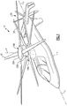
- FIG 1 schematically illustrates an exemplary high speed vertical takeoff and landing (VTOL) rotary-wing aircraft 10 having a counter-rotating, coaxial rotor system 12 which rotates about an axis of rotation A.
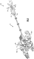
- the aircraft 10 includes an airframe 14 which supports a drive system 16 ( Figure 2 ) that generally includes the rotor system 12 as well as a translational thrust system 30 which provides translational thrust generally parallel to an aircraft longitudinal axis L while the main rotor system 12 operates in an unloaded reverse flow state during a high-speed forward flight profile.
- VTOL vertical takeoff and landing
- the rotor system 12 includes an upper rotor system 18A and a lower rotor system 18B.
- Each rotor system 18A, 18B includes a multiple of rotor blades 20 mounted to a respective rotor hub 22A, 22B for rotation about a rotor axis of rotation A. Any number of blades 20 may be used with the rotor system 12.
- the main rotor assembly 12 is driven about the axis of rotation A through a main gearbox (MGB) 24 by a multi-engine powerplant system 26 - here having two engine packages ENG1, ENG2.
- the multi-engine powerplant system 26 generates the power available for flight operations and couples such power to the main rotor assembly 12 and the translational thrust system 30 through the MGB 24.
- the MGB 24 may be interposed between the powerplant system 26, the rotor system 12 and the translational thrust system 30.
- the translational thrust system 30 in one non-limiting embodiment may be mounted to the rear of the airframe 14 with the rotational axis T oriented substantially horizontal and parallel to the aircraft longitudinal axis L to provide thrust for high-speed flight. It should be understood that other configurations of the translational thrust system such as a propeller system mounted to each side of the air frame may alternatively be utilized.
- the translational thrust system 30 includes a pusher propeller system 32.
- a portion of the drive system 16 downstream of the MGB 24 includes a combined gearbox 34.
- the combined gearbox 34 selectively operates as a clutch and a brake for operation of the translational thrust system 30 with the MGB 24.
- the combined gearbox 34 also operates to provide a rotor brake function for the main rotor system 12.
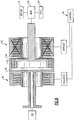
- the combined gearbox 34 generally includes an input 40 (see also Figure 2 ), a second brake system 42, a planetary gear system 44, a first brake system 46 and an output 48 (see also Figure 2 ) generally defined along an axis W which is generally parallel to rotational axis T.
- the input 40 is generally upstream of the combined gearbox 34 relative the MGB 24 and the output 48 is downstream of the combined gearbox 34 and upstream of the pusher propeller system 32 ( Figure 2 ).
- the functions of the second brake system 42 and the first brake system 46 respectively include transferring torque from an input shaft to an output shaft (clutching) or stopping and holding a load (braking). Though offered as separate brake components, their functions may be combined into a single unit disclosed herein.
- the second brake system 42 and the first brake system 46 may be categorized by the technique used to engage or stop the load such as friction, electromagnetic, mechanical lockup, etc, and by the method used to actuate such as mechanical, electric, pneumatic, hydraulic, self-activating, etc. It should be understood that various second brake systems and first brake systems may be utilized to include but not to be limited to mechanical, electrically, hydraulic and various combinations thereof.
- the input 40 is located within the drive system 34 downstream of the MGB 24.
- the output 48 is located within the drive system 34 upstream of the translational thrust system 30.
- the combined gearbox 34 is located just upstream of the pusher propeller system 32. It should be understood that various interfaces may be utilized to mount the combined gearbox 34 within the drive system 34.
- the input 40 is mounted to a sun gear 50 which is in meshing engagement with a multiple of planet gears 52.
- the multiple of planet gears 52 are supported on a planet carrier 54.
- the multiple of planet gears 52 are in meshing engagement with an output ring gear 56 mounted to the output 48.
- the second brake system 42 includes a second brake plate assembly 58 fixed to the planet carrier 54 ( Figure 5 ) and a second clutch actuator 60 fixed to ground such as the aircraft airframe 14.
- the second clutch actuator 60 selectively engages the second brake plate assembly 58 such that the planet carrier 54 is stationary during engagement. Power is thereby driven from the sun gear 50 though the multiple of planet gears 52 and into the output ring gear 56.
- the overall reduction ratio between the input 40 and the output 48 is the ratio of the radius of the sun gear 50 to output ring gear 56.
- the first brake system 46 includes a first brake plate assembly 62 fixed to the output ring gear 56 ( Figure 5 ) and a first brake actuator 64 which is fixed to ground such as the aircraft airframe 14.
- the first brake actuator 64 selectively engages the first brake plate assembly 62 such that the output ring gear 56 is stationary and the planet carrier 54 is free to rotate during engagement. Power is thereby driven from the sun gear 50 and into the multiple of planet gears 52 which freely rotate but drive nothing.
- selective operation of the second brake system 42 and the first brake system 46 within the combined gearbox 34 may be performed through a translational thrust system algorithm.
- the "brake system” is the first brake system 46 and the “clutch system” is the second brake system 42.
- the functions of the translational thrust system algorithm are disclosed in terms of functional block diagrams, and it should be understood by those skilled in the art with the benefit of this disclosure that these functions may be enacted in either dedicated hardware circuitry or programmed software routines capable of execution in a microprocessor based electronics control embodiment such as a control module M.
- the module may be a portion of a flight control computer, a portion of a central vehicle control, an interactive vehicle dynamics module, a stand-alone line replaceable unit or other system.
- the module typically includes a processor, a memory and an interface.
- the processor may, for example only, be any type of known microprocessor having desired performance characteristics.
- the memory may, for example only, includes UVPROM, EEPROM, FLASH, RAM, ROM, DVD, CD, a hard drive, or other computer readable medium which may store data and the control algorithms for operation of the minimal actuation power algorithm as described herein.
- the interface facilitates communication with the other avionics and systems.
- the aircraft is on the ground such that the second brake system 42 and the first brake system 46 are applied ( Figure 7 ). It should be understood that applied as utilized herein may take various forms to rotationally lock the particular system 42, 46. With both the second brake system 42 and the first brake system 46 applied, the combined gearbox 34 provides a brake function for the main rotor system 12.
- the multi-engine powerplant system 26 is started and the second brake system 42 is released such that the main rotor system 12 may spin-up through the MGB 24.
- power from the MGB 24 drives the sun gear 50 within the multiple of planet gears 52 which freely rotate but drive nothing.
- the first brake system 46 is released and the second brake system 42 is applied to spin-up and absorb power from the MGB 24 into the translational thrust system 30 ( Figure 8 ).
- the sun gear 50 drives the multiple of planet gears 52.
- the multiple of planet gears 52 drive the output ring gear 56 to drive the output 48 and thus power the translational thrust system 30.
- the general difference between the first brake system 46 and the second brake system 42 is that the first brake system 46 need only perform a brake operation of the translational thrust system 30, however, the second brake system 42 may be required to feather-in power from the MGB 24 in a smooth clutch like motion to spin-up the translational thrust system 30.
- the second brake system 42 may therefore be of a somewhat different construction than the first brake system 46 such as, for example, to include additional brake plates.
- the translational thrust system 30 is assisted in spin-up from airflow therethrough when in a flight condition which facilitates the smooth clutch like motion.
- failure within either the first brake system 46 or the second brake system 42 results in a mechanical fail-safe condition in which neither the translational thrust system 30 nor rotor brake functionality will be active such that the aircraft can continue normal flight operations with the main rotor system 12 driven through the MGB 24.
- the translational thrust system 30 may be designed to absorb more power from the MGB 24 than the main rotor system 12 such that application of a rotor first brake system through the combined gearbox 34 downstream of the MGB 24 will brake the main rotor system 12.
Claims (15)
- Système d'entraînement (16) pour avion à voilure tournante comprenant :un système d'engrenage planétaire (44) qui comprend un engrenage solaire (50) en prise d'engrènement avec un multiple d'engrenages planétaires (52), ledit multiple d'engrenages planétaires (52) étant supporté sur un porte-satellites (54), ledit multiple d'engrenages planétaires (52) étant en prise d'engrènement avec une couronne dentée de sortie (56) ;une entrée (40) fixée audit engrenage solaire (50) dudit système d'engrenage planétaire (44) pour tourner avec elle ;une sortie (48) fixée à ladite couronne dentée de sortie (56) pour tourner avec elle, un système de poussée en translation (30) étant entraîné par ladite sortie (48) ;un premier système de freinage (46) pouvant être actionné sélectivement pour verrouiller en rotation ladite couronne dentée de sortie (56) ; etun second système de freinage (42) pouvant être actionné sélectivement pour verrouiller en rotation ledit porte-satellites dudit système d'engrenage planétaire (44).
- Système d'entraînement (16) selon la revendication 1, dans lequel ledit second système de freinage (42) comprend un ensemble de plaque de frein (58) fixé audit porte-satellites (54) .
- Système d'entraînement (16) selon la revendication 2, dans lequel ledit second système de freinage (42) comprend un actionneur d'embrayage (60) configuré pour être fixé au sol, ledit actionneur d'embrayage (60) pouvant être actionné sélectivement pour verrouiller en rotation ledit second ensemble de plaque de frein (58).
- Système d'entraînement (16) selon la revendication 3, dans lequel ledit second actionneur d'embrayage (60) est configuré pour être fixé à une cellule d'avion à voilure tournante (10).
- Système d'entraînement (16) selon l'une quelconque des revendications 1 à 4, dans lequel ledit premier système de freinage (46) comprend un ensemble de plaque de frein (62) fixé à ladite couronne dentée de sortie (56).
- Système d'entraînement (16) selon la revendication 5, dans lequel ledit premier système de freinage (46) comprend un actionneur de frein (64) configuré pour être fixé au sol, ledit actionneur de frein (60) pouvant être actionné sélectivement pour verrouiller en rotation ledit ensemble de plaque de frein (62).
- Système d'entraînement (16) selon la revendication 6, dans lequel ledit actionneur de frein (64) est configuré pour être fixé à une cellule d'avion à voilure tournante (10).
- Système d'entraînement (16) selon l'une quelconque des revendications 1 à 7, dans lequel un axe de rotation du système de rotor principal est transversal par rapport audit axe de rotation du système de poussée en translation.
- Système d'entraînement (16) selon l'une quelconque des revendications 1 à 8, dans lequel ledit premier système de freinage (46) et ledit second système de freinage (42) sont actionnés mécaniquement.
- Système d'entraînement (16) selon l'une quelconque des revendications 1 à 9, dans lequel ledit premier système de freinage (46) et ledit second système de freinage (42) sont actionnés électriquement.
- Système d'entraînement (16) selon l'une quelconque des revendications 1 à 10, dans lequel ledit premier système de freinage (46) et ledit second système de freinage (42) sont actionnés hydrauliquement.
- Système d'entraînement (16) selon l'une quelconque des revendications 1 à 11, dans lequel ledit premier système de freinage (46) et ledit second système de freinage (42) sont actionnés pneumatiquement.
- Procédé de freinage d'un système de rotor principal (12) d'un avion à voilure tournante (10) avec un système d'entraînement selon l'une quelconque des revendications 1 à 12, comprenant :l'entraînement d'un système de rotor principal (12) à travers une boîte de vitesse principale (24) ; etl'actionnement sélectif du second système de freinage (42) comme du premier système de freinage (46) en aval de la boîte de vitesse principale (24) pour freiner le système de rotor principal (12).
- Procédé selon la revendication 13, comprenant en outre :
l'application sélective du premier système de freinage (46) et la libération du second système de freinage (42) pour freiner un système de poussée en translation (30) autrement entraîné par la boîte de vitesse principale (24). - Procédé selon la revendication 13 ou 14, comprenant en outre :
l'application sélective du second système de freinage (42) et la libération du premier système de freinage (46) pour entraîner un système de poussée en translation par la boîte de vitesse principale (24).
Applications Claiming Priority (1)
| Application Number | Priority Date | Filing Date | Title |
|---|---|---|---|
| US17395409P | 2009-04-29 | 2009-04-29 |
Publications (3)
| Publication Number | Publication Date |
|---|---|
| EP2246255A2 EP2246255A2 (fr) | 2010-11-03 |
| EP2246255A3 EP2246255A3 (fr) | 2017-03-08 |
| EP2246255B1 true EP2246255B1 (fr) | 2018-12-26 |
Family
ID=42246203
Family Applications (1)
| Application Number | Title | Priority Date | Filing Date |
|---|---|---|---|
| EP10157515.7A Not-in-force EP2246255B1 (fr) | 2009-04-29 | 2010-03-24 | Système de commande d'embrayage de frein combiné et avion à voilure tournante l'utilisant |
Country Status (2)
| Country | Link |
|---|---|
| US (2) | US8475323B2 (fr) |
| EP (1) | EP2246255B1 (fr) |
Cited By (1)
| Publication number | Priority date | Publication date | Assignee | Title |
|---|---|---|---|---|
| US11592068B2 (en) | 2020-06-10 | 2023-02-28 | Rolls-Royce Corporation | Clutch assembly brake |
Families Citing this family (5)
| Publication number | Priority date | Publication date | Assignee | Title |
|---|---|---|---|---|
| EP2246255B1 (fr) | 2009-04-29 | 2018-12-26 | Sikorsky Aircraft Corporation | Système de commande d'embrayage de frein combiné et avion à voilure tournante l'utilisant |
| US8827204B2 (en) * | 2012-01-12 | 2014-09-09 | Hamilton Sundstrand Corporation | Clutch system for rotary-wing aircraft with secondary thrust system |
| WO2015031434A1 (fr) * | 2013-08-28 | 2015-03-05 | Sikorsky Aircraft Corporation | Boîte d'engrenages de propulseur légère |
| WO2016053408A1 (fr) * | 2014-10-01 | 2016-04-07 | Sikorsky Aircraft Corporation | Variation de signature acoustique d'aéronef mettant en oeuvre un embrayage |
| US10822076B2 (en) | 2014-10-01 | 2020-11-03 | Sikorsky Aircraft Corporation | Dual rotor, rotary wing aircraft |
Family Cites Families (30)
| Publication number | Priority date | Publication date | Assignee | Title |
|---|---|---|---|---|
| US716180A (en) * | 1901-06-13 | 1902-12-16 | Joseph F Coupe | Transforming-gear. |
| US737830A (en) * | 1902-09-04 | 1903-09-01 | Otho C Duryea | Hoist. |
| US1851146A (en) | 1930-03-20 | 1932-03-29 | Continental Illinois Bank & Tr | Automatic clutch |
| US2037766A (en) * | 1931-09-09 | 1936-04-21 | Autogiro Co Of America | Aircraft having autorotative sustaining means |
| US2838913A (en) * | 1950-07-15 | 1958-06-17 | Gen Motors Corp | Aircraft power system and clutch control therefor |
| US3035789A (en) * | 1957-11-27 | 1962-05-22 | Arthur M Young | Convertiplane |
| US3190414A (en) * | 1963-02-21 | 1965-06-22 | Chicago Aerial Ind Inc | Combination motor-transmission-brake |
| US3161241A (en) * | 1963-08-08 | 1964-12-15 | Ingersoll Rand Co | Rotary power hammer |
| US3977812A (en) * | 1975-11-17 | 1976-08-31 | The United States Of America As Represented By The Secretary Of The Army | Compound helicopter drive means |
| US4046235A (en) | 1976-04-19 | 1977-09-06 | Western Gear Corporation | Automatic load brake |
| US4216848A (en) | 1977-09-06 | 1980-08-12 | Hitachi, Ltd. | Centrifugal braking device |
| US4219107A (en) | 1977-12-13 | 1980-08-26 | Nasa | Speed control device for a heavy duty shaft |
| US4642029A (en) * | 1985-06-17 | 1987-02-10 | General Motors Corporation | Brake for counter rotating bladed members |
| US4798052A (en) | 1987-05-08 | 1989-01-17 | Allied-Signal Inc. | Constant-clearance brake piston system with braking pressure intensifier |
| US4976669A (en) * | 1989-07-20 | 1990-12-11 | Williams International Corporation | Dual output planetary gear system |
| JP3100216B2 (ja) | 1991-07-18 | 2000-10-16 | 株式会社シマノ | 釣り用リールのブレーキ機構 |
| IT1267971B1 (it) | 1994-01-11 | 1997-02-20 | Gf Gestioni Ind Srl | Dispositivo di frenatura per un rotore di un elicottero |
| US5853152A (en) | 1997-04-29 | 1998-12-29 | Sikorsky Aircraft Corporation | Collective detent system for vertical takeoff flight operations |
| US5855471A (en) | 1997-06-17 | 1999-01-05 | Sikorsky Aircraft Corporation | Helicopter rotor brake assembly |
| IT1293677B1 (it) | 1997-08-01 | 1999-03-08 | Finmeccanica Spa | Freno rotore per un elicottero. |
| US6193464B1 (en) | 1998-12-02 | 2001-02-27 | Mcdonnell Douglas Helicopter Company, | Active brake control for rotor/wing aircraft |
| US6019578A (en) | 1998-12-18 | 2000-02-01 | Sikorsky Aircraft Corporation | Variable diameter rotor blade actuation system |
| US6030177A (en) | 1998-12-18 | 2000-02-29 | Sikorsky Aircraft Corporation | Drive system for a variable diameter tilt rotor |
| JP4345146B2 (ja) * | 1999-07-29 | 2009-10-14 | アイシン精機株式会社 | 変速装置 |
| US6920965B2 (en) * | 2000-10-18 | 2005-07-26 | Continental Teves Ag & Co. Ohg | Spot-type disc brake with a spring assembly for a brake pad |
| US6428443B1 (en) * | 2001-01-29 | 2002-08-06 | Delphi Oracle Corp. | Split torque epicyclic gearing |
| DE10343055B4 (de) | 2003-09-16 | 2007-03-29 | Eurocopter Deutschland Gmbh | Rotorbremse |
| FR2864027B1 (fr) | 2003-12-19 | 2006-02-10 | Eurocopter France | Dispositif de freinage du rotor d'un helicoptere ou analogue associant un mecanisme de freinage principal a disque et un mecanisme de freinage secondaire sous grand vent |
| US7083142B2 (en) | 2004-04-21 | 2006-08-01 | Sikorsky Aircraft Corporation | Compact co-axial rotor system for a rotary wing aircraft and a control system thereof |
| EP2246255B1 (fr) | 2009-04-29 | 2018-12-26 | Sikorsky Aircraft Corporation | Système de commande d'embrayage de frein combiné et avion à voilure tournante l'utilisant |
-
2010
- 2010-03-24 EP EP10157515.7A patent/EP2246255B1/fr not_active Not-in-force
- 2010-04-13 US US12/758,874 patent/US8475323B2/en active Active
-
2013
- 2013-06-13 US US13/917,050 patent/US8613686B2/en active Active
Non-Patent Citations (1)
| Title |
|---|
| None * |
Cited By (1)
| Publication number | Priority date | Publication date | Assignee | Title |
|---|---|---|---|---|
| US11592068B2 (en) | 2020-06-10 | 2023-02-28 | Rolls-Royce Corporation | Clutch assembly brake |
Also Published As
| Publication number | Publication date |
|---|---|
| US20100279815A1 (en) | 2010-11-04 |
| EP2246255A2 (fr) | 2010-11-03 |
| EP2246255A3 (fr) | 2017-03-08 |
| US8613686B2 (en) | 2013-12-24 |
| US8475323B2 (en) | 2013-07-02 |
| US20130274061A1 (en) | 2013-10-17 |
Similar Documents
| Publication | Publication Date | Title |
|---|---|---|
| JP4727724B2 (ja) | 高速回転翼航空機用のロータ駆動装置および制御システム | |
| US8931732B2 (en) | Electric powered rotary-wing aircraft | |
| EP3738887B1 (fr) | Double entrée de moteur avec embrayage à roue libre | |
| US8613686B2 (en) | Combination brake clutch drive system and rotary-wing aircraft using same | |
| EP1954564B1 (fr) | Boite de transmission a vitesse variable comprenant un systeme de rotor de queue a vitesse independamment variable pour un aeronef a voilure tournante | |
| JP4681048B2 (ja) | 回転翼航空機用の可変変速機 | |
| EP3495260B1 (fr) | Systèmes de propulsion de rotor double pour aéronef à rotors basculants | |
| KR101390458B1 (ko) | 회전 날개를 가지는 하이브리드 항공기 | |
| US10106255B2 (en) | Rotary pylon conversion actuator for tiltrotor aircraft | |
| US9290266B2 (en) | Speed control assembly and methods of using same | |
| US8083172B2 (en) | Combination spar and trunnion structure for a tilt rotor aircraft | |
| US20150375860A1 (en) | Tilt-rotor vertical-lift aircraft | |
| WO2009126905A1 (fr) | Actionnement d'un basculement pour un giravion | |
| EP3038906B1 (fr) | Boîte d'engrenages de propulseur légère | |
| EP3933228B1 (fr) | Arbres d'entrée et de sortie coaxiaux étanches | |
| US10745118B2 (en) | Variable ratio gearbox for a rotary wing aircraft tail rotor |
Legal Events
| Date | Code | Title | Description |
|---|---|---|---|
| PUAI | Public reference made under article 153(3) epc to a published international application that has entered the european phase |
Free format text: ORIGINAL CODE: 0009012 |
|
| AK | Designated contracting states |
Kind code of ref document: A2 Designated state(s): AT BE BG CH CY CZ DE DK EE ES FI FR GB GR HR HU IE IS IT LI LT LU LV MC MK MT NL NO PL PT RO SE SI SK SM TR |
|
| AX | Request for extension of the european patent |
Extension state: AL BA ME RS |
|
| PUAL | Search report despatched |
Free format text: ORIGINAL CODE: 0009013 |
|
| AK | Designated contracting states |
Kind code of ref document: A3 Designated state(s): AT BE BG CH CY CZ DE DK EE ES FI FR GB GR HR HU IE IS IT LI LT LU LV MC MK MT NL NO PL PT RO SE SI SK SM TR |
|
| AX | Request for extension of the european patent |
Extension state: AL BA ME RS |
|
| RIC1 | Information provided on ipc code assigned before grant |
Ipc: B64C 27/14 20060101AFI20170201BHEP Ipc: F16H 3/44 20060101ALI20170201BHEP |
|
| STAA | Information on the status of an ep patent application or granted ep patent |
Free format text: STATUS: REQUEST FOR EXAMINATION WAS MADE |
|
| 17P | Request for examination filed |
Effective date: 20170907 |
|
| RBV | Designated contracting states (corrected) |
Designated state(s): AT BE BG CH CY CZ DE DK EE ES FI FR GB GR HR HU IE IS IT LI LT LU LV MC MK MT NL NO PL PT RO SE SI SK SM TR |
|
| RIC1 | Information provided on ipc code assigned before grant |
Ipc: F16H 3/44 20060101ALI20180404BHEP Ipc: B64C 27/14 20060101AFI20180404BHEP |
|
| GRAP | Despatch of communication of intention to grant a patent |
Free format text: ORIGINAL CODE: EPIDOSNIGR1 |
|
| STAA | Information on the status of an ep patent application or granted ep patent |
Free format text: STATUS: GRANT OF PATENT IS INTENDED |
|
| INTG | Intention to grant announced |
Effective date: 20180718 |
|
| GRAS | Grant fee paid |
Free format text: ORIGINAL CODE: EPIDOSNIGR3 |
|
| GRAA | (expected) grant |
Free format text: ORIGINAL CODE: 0009210 |
|
| STAA | Information on the status of an ep patent application or granted ep patent |
Free format text: STATUS: THE PATENT HAS BEEN GRANTED |
|
| AK | Designated contracting states |
Kind code of ref document: B1 Designated state(s): AT BE BG CH CY CZ DE DK EE ES FI FR GB GR HR HU IE IS IT LI LT LU LV MC MK MT NL NO PL PT RO SE SI SK SM TR |
|
| REG | Reference to a national code |
Ref country code: GB Ref legal event code: FG4D |
|
| REG | Reference to a national code |
Ref country code: CH Ref legal event code: EP |
|
| REG | Reference to a national code |
Ref country code: DE Ref legal event code: R096 Ref document number: 602010056006 Country of ref document: DE |
|
| REG | Reference to a national code |
Ref country code: AT Ref legal event code: REF Ref document number: 1081050 Country of ref document: AT Kind code of ref document: T Effective date: 20190115 |
|
| REG | Reference to a national code |
Ref country code: IE Ref legal event code: FG4D |
|
| PG25 | Lapsed in a contracting state [announced via postgrant information from national office to epo] |
Ref country code: LT Free format text: LAPSE BECAUSE OF FAILURE TO SUBMIT A TRANSLATION OF THE DESCRIPTION OR TO PAY THE FEE WITHIN THE PRESCRIBED TIME-LIMIT Effective date: 20181226 Ref country code: BG Free format text: LAPSE BECAUSE OF FAILURE TO SUBMIT A TRANSLATION OF THE DESCRIPTION OR TO PAY THE FEE WITHIN THE PRESCRIBED TIME-LIMIT Effective date: 20190326 Ref country code: HR Free format text: LAPSE BECAUSE OF FAILURE TO SUBMIT A TRANSLATION OF THE DESCRIPTION OR TO PAY THE FEE WITHIN THE PRESCRIBED TIME-LIMIT Effective date: 20181226 Ref country code: NO Free format text: LAPSE BECAUSE OF FAILURE TO SUBMIT A TRANSLATION OF THE DESCRIPTION OR TO PAY THE FEE WITHIN THE PRESCRIBED TIME-LIMIT Effective date: 20190326 Ref country code: LV Free format text: LAPSE BECAUSE OF FAILURE TO SUBMIT A TRANSLATION OF THE DESCRIPTION OR TO PAY THE FEE WITHIN THE PRESCRIBED TIME-LIMIT Effective date: 20181226 Ref country code: FI Free format text: LAPSE BECAUSE OF FAILURE TO SUBMIT A TRANSLATION OF THE DESCRIPTION OR TO PAY THE FEE WITHIN THE PRESCRIBED TIME-LIMIT Effective date: 20181226 |
|
| REG | Reference to a national code |
Ref country code: NL Ref legal event code: MP Effective date: 20181226 |
|
| REG | Reference to a national code |
Ref country code: LT Ref legal event code: MG4D |
|
| PG25 | Lapsed in a contracting state [announced via postgrant information from national office to epo] |
Ref country code: SE Free format text: LAPSE BECAUSE OF FAILURE TO SUBMIT A TRANSLATION OF THE DESCRIPTION OR TO PAY THE FEE WITHIN THE PRESCRIBED TIME-LIMIT Effective date: 20181226 Ref country code: GR Free format text: LAPSE BECAUSE OF FAILURE TO SUBMIT A TRANSLATION OF THE DESCRIPTION OR TO PAY THE FEE WITHIN THE PRESCRIBED TIME-LIMIT Effective date: 20190327 |
|
| REG | Reference to a national code |
Ref country code: AT Ref legal event code: MK05 Ref document number: 1081050 Country of ref document: AT Kind code of ref document: T Effective date: 20181226 |
|
| PG25 | Lapsed in a contracting state [announced via postgrant information from national office to epo] |
Ref country code: NL Free format text: LAPSE BECAUSE OF FAILURE TO SUBMIT A TRANSLATION OF THE DESCRIPTION OR TO PAY THE FEE WITHIN THE PRESCRIBED TIME-LIMIT Effective date: 20181226 |
|
| PG25 | Lapsed in a contracting state [announced via postgrant information from national office to epo] |
Ref country code: PT Free format text: LAPSE BECAUSE OF FAILURE TO SUBMIT A TRANSLATION OF THE DESCRIPTION OR TO PAY THE FEE WITHIN THE PRESCRIBED TIME-LIMIT Effective date: 20190426 Ref country code: IT Free format text: LAPSE BECAUSE OF FAILURE TO SUBMIT A TRANSLATION OF THE DESCRIPTION OR TO PAY THE FEE WITHIN THE PRESCRIBED TIME-LIMIT Effective date: 20181226 Ref country code: CZ Free format text: LAPSE BECAUSE OF FAILURE TO SUBMIT A TRANSLATION OF THE DESCRIPTION OR TO PAY THE FEE WITHIN THE PRESCRIBED TIME-LIMIT Effective date: 20181226 Ref country code: PL Free format text: LAPSE BECAUSE OF FAILURE TO SUBMIT A TRANSLATION OF THE DESCRIPTION OR TO PAY THE FEE WITHIN THE PRESCRIBED TIME-LIMIT Effective date: 20181226 Ref country code: ES Free format text: LAPSE BECAUSE OF FAILURE TO SUBMIT A TRANSLATION OF THE DESCRIPTION OR TO PAY THE FEE WITHIN THE PRESCRIBED TIME-LIMIT Effective date: 20181226 |
|
| PG25 | Lapsed in a contracting state [announced via postgrant information from national office to epo] |
Ref country code: IS Free format text: LAPSE BECAUSE OF FAILURE TO SUBMIT A TRANSLATION OF THE DESCRIPTION OR TO PAY THE FEE WITHIN THE PRESCRIBED TIME-LIMIT Effective date: 20190426 Ref country code: RO Free format text: LAPSE BECAUSE OF FAILURE TO SUBMIT A TRANSLATION OF THE DESCRIPTION OR TO PAY THE FEE WITHIN THE PRESCRIBED TIME-LIMIT Effective date: 20181226 Ref country code: SK Free format text: LAPSE BECAUSE OF FAILURE TO SUBMIT A TRANSLATION OF THE DESCRIPTION OR TO PAY THE FEE WITHIN THE PRESCRIBED TIME-LIMIT Effective date: 20181226 Ref country code: EE Free format text: LAPSE BECAUSE OF FAILURE TO SUBMIT A TRANSLATION OF THE DESCRIPTION OR TO PAY THE FEE WITHIN THE PRESCRIBED TIME-LIMIT Effective date: 20181226 Ref country code: SM Free format text: LAPSE BECAUSE OF FAILURE TO SUBMIT A TRANSLATION OF THE DESCRIPTION OR TO PAY THE FEE WITHIN THE PRESCRIBED TIME-LIMIT Effective date: 20181226 |
|
| REG | Reference to a national code |
Ref country code: DE Ref legal event code: R097 Ref document number: 602010056006 Country of ref document: DE |
|
| PG25 | Lapsed in a contracting state [announced via postgrant information from national office to epo] |
Ref country code: AT Free format text: LAPSE BECAUSE OF FAILURE TO SUBMIT A TRANSLATION OF THE DESCRIPTION OR TO PAY THE FEE WITHIN THE PRESCRIBED TIME-LIMIT Effective date: 20181226 Ref country code: DK Free format text: LAPSE BECAUSE OF FAILURE TO SUBMIT A TRANSLATION OF THE DESCRIPTION OR TO PAY THE FEE WITHIN THE PRESCRIBED TIME-LIMIT Effective date: 20181226 Ref country code: MC Free format text: LAPSE BECAUSE OF FAILURE TO SUBMIT A TRANSLATION OF THE DESCRIPTION OR TO PAY THE FEE WITHIN THE PRESCRIBED TIME-LIMIT Effective date: 20181226 |
|
| REG | Reference to a national code |
Ref country code: CH Ref legal event code: PL |
|
| PLBE | No opposition filed within time limit |
Free format text: ORIGINAL CODE: 0009261 |
|
| STAA | Information on the status of an ep patent application or granted ep patent |
Free format text: STATUS: NO OPPOSITION FILED WITHIN TIME LIMIT |
|
| PG25 | Lapsed in a contracting state [announced via postgrant information from national office to epo] |
Ref country code: LU Free format text: LAPSE BECAUSE OF NON-PAYMENT OF DUE FEES Effective date: 20190324 |
|
| 26N | No opposition filed |
Effective date: 20190927 |
|
| REG | Reference to a national code |
Ref country code: BE Ref legal event code: MM Effective date: 20190331 |
|
| PG25 | Lapsed in a contracting state [announced via postgrant information from national office to epo] |
Ref country code: CH Free format text: LAPSE BECAUSE OF NON-PAYMENT OF DUE FEES Effective date: 20190331 Ref country code: LI Free format text: LAPSE BECAUSE OF NON-PAYMENT OF DUE FEES Effective date: 20190331 Ref country code: IE Free format text: LAPSE BECAUSE OF NON-PAYMENT OF DUE FEES Effective date: 20190324 |
|
| PG25 | Lapsed in a contracting state [announced via postgrant information from national office to epo] |
Ref country code: SI Free format text: LAPSE BECAUSE OF FAILURE TO SUBMIT A TRANSLATION OF THE DESCRIPTION OR TO PAY THE FEE WITHIN THE PRESCRIBED TIME-LIMIT Effective date: 20181226 Ref country code: BE Free format text: LAPSE BECAUSE OF NON-PAYMENT OF DUE FEES Effective date: 20190331 |
|
| PG25 | Lapsed in a contracting state [announced via postgrant information from national office to epo] |
Ref country code: TR Free format text: LAPSE BECAUSE OF FAILURE TO SUBMIT A TRANSLATION OF THE DESCRIPTION OR TO PAY THE FEE WITHIN THE PRESCRIBED TIME-LIMIT Effective date: 20181226 |
|
| PGFP | Annual fee paid to national office [announced via postgrant information from national office to epo] |
Ref country code: DE Payment date: 20200327 Year of fee payment: 11 Ref country code: GB Payment date: 20200327 Year of fee payment: 11 |
|
| PG25 | Lapsed in a contracting state [announced via postgrant information from national office to epo] |
Ref country code: MT Free format text: LAPSE BECAUSE OF NON-PAYMENT OF DUE FEES Effective date: 20190324 |
|
| PGFP | Annual fee paid to national office [announced via postgrant information from national office to epo] |
Ref country code: FR Payment date: 20200325 Year of fee payment: 11 |
|
| PG25 | Lapsed in a contracting state [announced via postgrant information from national office to epo] |
Ref country code: CY Free format text: LAPSE BECAUSE OF FAILURE TO SUBMIT A TRANSLATION OF THE DESCRIPTION OR TO PAY THE FEE WITHIN THE PRESCRIBED TIME-LIMIT Effective date: 20181226 |
|
| PG25 | Lapsed in a contracting state [announced via postgrant information from national office to epo] |
Ref country code: HU Free format text: LAPSE BECAUSE OF FAILURE TO SUBMIT A TRANSLATION OF THE DESCRIPTION OR TO PAY THE FEE WITHIN THE PRESCRIBED TIME-LIMIT; INVALID AB INITIO Effective date: 20100324 |
|
| REG | Reference to a national code |
Ref country code: DE Ref legal event code: R119 Ref document number: 602010056006 Country of ref document: DE |
|
| GBPC | Gb: european patent ceased through non-payment of renewal fee |
Effective date: 20210324 |
|
| PG25 | Lapsed in a contracting state [announced via postgrant information from national office to epo] |
Ref country code: GB Free format text: LAPSE BECAUSE OF NON-PAYMENT OF DUE FEES Effective date: 20210324 Ref country code: FR Free format text: LAPSE BECAUSE OF NON-PAYMENT OF DUE FEES Effective date: 20210331 Ref country code: DE Free format text: LAPSE BECAUSE OF NON-PAYMENT OF DUE FEES Effective date: 20211001 |
|
| PG25 | Lapsed in a contracting state [announced via postgrant information from national office to epo] |
Ref country code: MK Free format text: LAPSE BECAUSE OF FAILURE TO SUBMIT A TRANSLATION OF THE DESCRIPTION OR TO PAY THE FEE WITHIN THE PRESCRIBED TIME-LIMIT Effective date: 20181226 |