EP2244428B1 - Communication apparatus for transmitting data through a plurality of data-paths - Google Patents
Communication apparatus for transmitting data through a plurality of data-paths Download PDFInfo
- Publication number
- EP2244428B1 EP2244428B1 EP10159481A EP10159481A EP2244428B1 EP 2244428 B1 EP2244428 B1 EP 2244428B1 EP 10159481 A EP10159481 A EP 10159481A EP 10159481 A EP10159481 A EP 10159481A EP 2244428 B1 EP2244428 B1 EP 2244428B1
- Authority
- EP
- European Patent Office
- Prior art keywords
- card
- primary
- data
- communication apparatus
- route
- Prior art date
- Legal status (The legal status is an assumption and is not a legal conclusion. Google has not performed a legal analysis and makes no representation as to the accuracy of the status listed.)
- Not-in-force
Links
Images


Classifications
-
- H—ELECTRICITY
- H04—ELECTRIC COMMUNICATION TECHNIQUE
- H04L—TRANSMISSION OF DIGITAL INFORMATION, e.g. TELEGRAPHIC COMMUNICATION
- H04L45/00—Routing or path finding of packets in data switching networks
-
- H—ELECTRICITY
- H04—ELECTRIC COMMUNICATION TECHNIQUE
- H04L—TRANSMISSION OF DIGITAL INFORMATION, e.g. TELEGRAPHIC COMMUNICATION
- H04L45/00—Routing or path finding of packets in data switching networks
- H04L45/24—Multipath
- H04L45/243—Multipath using M+N parallel active paths
-
- H—ELECTRICITY
- H04—ELECTRIC COMMUNICATION TECHNIQUE
- H04L—TRANSMISSION OF DIGITAL INFORMATION, e.g. TELEGRAPHIC COMMUNICATION
- H04L45/00—Routing or path finding of packets in data switching networks
- H04L45/24—Multipath
- H04L45/245—Link aggregation, e.g. trunking
-
- H—ELECTRICITY
- H04—ELECTRIC COMMUNICATION TECHNIQUE
- H04L—TRANSMISSION OF DIGITAL INFORMATION, e.g. TELEGRAPHIC COMMUNICATION
- H04L45/00—Routing or path finding of packets in data switching networks
- H04L45/28—Routing or path finding of packets in data switching networks using route fault recovery
-
- H—ELECTRICITY
- H04—ELECTRIC COMMUNICATION TECHNIQUE
- H04L—TRANSMISSION OF DIGITAL INFORMATION, e.g. TELEGRAPHIC COMMUNICATION
- H04L45/00—Routing or path finding of packets in data switching networks
- H04L45/58—Association of routers
- H04L45/583—Stackable routers
Definitions
- the present invention relates to a communication apparatus for transmitting data through a plurality of data-paths.
- a communication system in which base stations are connected to each other through multiple data-paths by using a multi-homing method has been put into practical use.
- S3G Super 3G
- a communication system in which base stations are connected to each other through multiple data-paths by using a multi-homing method has been put into practical use.
- Japanese Laid-Open Patent Application Publication No. 2000-209278 and 2006-279467 disclose about a communication system in which a multi-homing method is employed.
- a network within a company can be connected to another network outside the company through a plurality of data-paths, for example, using a plurality of ISPs (Internet Service Providers).
- ISPs Internet Service Providers
- a communication apparatus such as a base station
- a card for handling SCTP Stream Control Transmission Protocol
- the card may have, for example, two link ports each connected to a link port of another communication apparatus with which the base station communicates.
- the card may be configured to include a SCTP handler that terminates a SCTP signal.
- one of the two link ports is used for a primary data-path and the other one for a secondary data-path where a global address is assigned to each of the two link ports.
- Data is transmitted and received through the primary data-path under normal conditions, and the secondary data-path is used as an alternate path when the primary data-path is disconnected, for example, due to a failure.
- the secondary data-path is used as an alternate path when the primary data-path is disconnected, for example, due to a failure.
- a communication apparatus such as a base station
- Adopting a redundant card requires each of primary and secondary data-paths to be accommodated in a different card.
- a multi-homing method may not be applied since the primary and secondary data-paths are handled independently by each of SCTP handlers of two different cards.
- an access controller of the card which is normally configured to provide services such as call processing, to perform a multi-homing communication.
- this causes another problem that the load of the access controller becomes higher, thereby exerting an adverse effect on providing the above-mentioned services such as call processing.
- the card may be assigned with one global address and one local address.
- a multi-homing method according to SCTP uses two global addresses each assigned to one of primary and secondary data-paths.
- the SCTP handler of the card may try to start a communication with another communication apparatus using both the global address and the local address which are assigned to the card.
- the communication using the local address fails since the local address is effective only within the communication apparatus.
- a multi-homing communication with another communication apparatus may not be performed. This case is also undesirable from the aspect of security because the local address for the card of the communication apparatus may flow out into the network.
- WO 02/096035 discloses a data communications network having a primary router, a secondary router and a peer router.
- the primary and peer routers conduct a peer session to exchange information regarding the current state of the network topology.
- the secondary router monitors the peer session to maintain awareness of the current state of the network topology and replaces the primary router upon detecting a failure of the primary router.
- a communication apparatus for transmitting data through a plurality of data-paths as defined in claim 1.
- Preferred features are defined In the dependent claims.
- FIG. 1 is a diagram illustrating a configuration example of a communication apparatus, according to an embodiment
- FIG. 2 is a block diagram illustrating a configuration example of a signal processor of a primary card, according to an embodiment
- FIG. 3 is a block diagram illustrating a configuration example of a signal processor of a secondary card, according to an embodiment
- FIG. 4 is a diagram illustrating an example of an operational flowchart of primary and secondary cards, according to an embodiment
- FIG. 5 is a schematic diagram illustrating an example of data encapsulated by a secondary card, according to an embodiment
- FIG. 6 is a diagram illustrating an example of an operational flowchart of a secondary card when transmitting secondary data to another communication apparatus, according to an embodiment
- FIG. 7 is a schematic diagram illustrating an example of data decapsulated by a secondary card, according to an embodiment
- FIG. 8 is a diagram illustrating an example of information stored in a memory of a primary card, according to an embodiment
- FIG. 9 is a diagram illustrating an example of information stored in a memory of a secondary card, according to an embodiment
- FIG. 10 is a schematic diagram illustrating an operational example of a communication apparatus when a failure has occurred in a primary card, according to an embodiment
- FIG. 11 is a schematic diagram illustrating an operational example of a communication apparatus when the failure has recovered, according to an embodiment
- FIG. 12 is a schematic diagram illustrating an example of an operation of a communication apparatus when a failure has occurred in a secondary card, according to an embodiment
- FIG. 13 is a diagram illustrating an example of an operational flowchart for starting up one of first and second cards, according to an embodiment
- FIG. 14 is a schematic diagram illustrating an example of a procedure for setting a value to mode information when a first card starts up, according to an embodiment
- FIG. 15 is a schematic diagram illustrating an operation example for monitoring operating states of first and second cards by an access controller, according to an embodiment
- FIG. 16 is a schematic diagram illustrating an operation example for monitoring operating states of first and second cards by an access controller, according to an embodiment
- FIG. 17 is a schematic diagram illustrating an operation example for maintaining a first card, according to an embodiment
- FIG. 18 is a schematic diagram illustrating an operation example for monitoring operating states of first and second cards by a setting part, according to an embodiment
- FIG. 19 is a schematic diagram illustrating an operation example for monitoring operating states of first and second cards by a setting part, according to an embodiment.
- FIG. 20 is a diagram illustrating a configuration example of a communication system, according to an embodiment.
- a communication tunnel is formed through a card-to-card link between first and second cards. This allows one of the first and second cards to perform a communication with another communication apparatus through the other one of the first and second cards using the communication tunnel, and a multi-homing communication using a plurality of data-paths can be performed with a redundant configuration of the first and second cards.
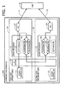
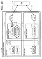
- FIG. 1 is a diagram illustrating a configuration example of a communication apparatus, according to an embodiment.
- a communication apparatus 100 may be, for example, an evolutional Node B (eNB) that communicates with a higher level system. As depicted in FIG. 1 , the communication apparatus 100 may be configured to include a first card 110, a second card 120, and a L2 switch 130. The L2 switch 130 functions as a card-to-card link between the first and second cards. The communication apparatus 100 performs transmission of data between the communication apparatus 100 and another communication apparatus (for example, a MME 10 as depicted in FIG. 1 ) through a first route 11 connected to the first card 110 and a second route connected to the second card 120.
- eNB evolutional Node B
- a pair of one global address and one local address are assigned to each of the first and second cards 110, 120.
- A be a global address assigned to the first card 110 and let “B” be a global address assigned to the second card 120.
- the first card 110 includes, for example, an access controller 111, a signal processor 112, and a NIC (network interface card) 114.
- the signal processor 112 may be configured to include, for example, a SCTP handler 113 as a protocol handler, an encapsulator 241, and decapsulator 242.
- the second card 120 includes, for example, an access controller 121, a signal processor 122, and a NIC 124.
- the signal processor 122 may be configured to include, for example, a SCTP handler 123 as a protocol handler, an encapsulator 341, and decapsulator 342.
- the first card 110 and the second card 120 communicate with each other via the L2 SWITCH 130 (Layer 2 Switch) that functions as a card-to-card link between the first and second cards.
- Layer 2 Switch Layer 2 Switch
- the access controller 111 is a controller for controlling the first card 110
- the access controller 121 is a controller for controlling the second card 120.
- one of the access controllers 111, 121 is in an active state and the other one is in a standby state.
- a card in which the access controller is in an active state is referred to as "a primary card”
- a card in which the access controller is in a standby state is referred to as "a secondary card”.
- a primary card a card in which the access controller is in a standby state
- a secondary card a card in which the access controller is in a standby state
- the access controller 111 in an active state operates as a main controller for controlling both the first and second cards. That is, in this case, the first card 110 including the access controller 111 of an active state is operated as a primary card that controls both the first and second cards.
- the access controller 111 of the first card 110 (the primary card) may provide services, such as call control service and a handover service, in cooperation with a SCTP handler 113 of the first card 110. These services may be provided, for example, in accordance with the 3GPP/LTE.
- the access controller 121 of the second card 120 (the secondary card), which is at present in a standby state, remains in the standby state until the access controller 111, which is at present in an active state, turns into an OOS (Out Of Service) state, for example, due to a failure or a maintenance operation.
- OOS Out Of Service
- the access controller 121 of the secondary card 120 shifts to an active state, in other words, the second card 120 becomes a primary card that controls both the first and second cards.
- the signal processor 112 of the first card 110 may be, for example, a NWP (Network Processor) having a security function.
- the signal processor 112 includes a protocol handler 113 for handling a given protocol that establishes a plurality of data-paths and performs a transmission of data through the established plurality of data-paths.
- a SCTP is used as the given protocol
- a SCTP handler 113 that terminates the SCTP is depicted as an example of a protocol handler.
- the SCTP handler 113 performs a multi-homing communication with the MME 10 using a first route 11 connected to the first card 110 and a second route 12 connected to the second card 120.
- a multi-homing communication requires two data-paths each established along a different transmission-route.
- One of the two data-paths is used for transmitting primary data and hereinafter referred to as "a primary data-path”.
- the other one of the two data-paths is used as a backup data-path for the primary data-path or may be used for transmitting secondary data, and hereinafter referred to as "a secondary data-path”.
- the primary data-path is established along a primary transmission-route that is set to connect the SCTP handler 113, a NIC 114, and a first route 11 connected to the first card 120.
- the secondary data-path is established along a secondary transmission-route that is set to connect the SCTP handler 113, the encapsulator 241 and the decapsulator 242 of the signal processor 112, the L2 switch 130 (a card-to-card link), the encapsulator 341 and the decapsulator 342 of the signal processor 122, a NIC 124, and a second route 12 connected to the second card 120.
- the SCTP handler 113 when establishing two data-paths from the SCTP handler 113 to the MME 10, issues two connection requests (INIT) to the MME 10, notifying the MME 10 of the global address "A" assigned to the first card 110 and the global address "B" assigned to the second card 120.
- IIT connection requests
- the SCTP handler 113 of the first card 110 starts a multi-homing communication with MME 10.
- the SCTP handler 113 monitors each state of the primary and secondary data-paths, and determines one of the primary and secondary data-paths to be a data-path through which primary data is to be transmitted. For example, the SCTP handler 113 transmits primary data through the primary data-path under normal conditions, and determines the existing secondary data-path to be a new primary data-path when a failure has occurred in the existing primary data-path so as to transmit the primary data through the new primary data-path.
- the primary card 110 sets a primary transmission-route through which a primary data-path is to be established, and sets a secondary transmission-route through which a secondary data-path is to be established.
- the primary data-route is set as a route, from the SCTP handler 113 to the MME 10, that passes through the NIC 114 and the first-route 11 connected to the first card 110, as mentioned above.
- the secondary transmission-route is set as a route, from the SCTP handler 113 to the MME 10, that passes through the L2 switch 130, the signal processor 122, and the NIC 124, as mentioned above.
- the SCTP handler 113 of the first card 110 (a primary card) sends primary data to the MME 10 through the primary data-path that is established along the primary transmission-route.
- the signal processor 112 of the first card 110 transmits the primary data to the MME 10 through the primary data-path using, as a source address of the primary data, the global address "A" assigned to the first card 110.
- the SCTP handler 113 of the first card 110 sends secondary data to the MME 10 through the secondary data-path that is established along the secondary transmission-route.
- the signal processor 112 of the first card 110 encapsulates the secondary data, and transfers the encapsulated secondary data to the second card 120 (a secondary card) via the card-to-card link (in the case, the L2 switch 130).
- the signal processor 112 of the first card 110 may be configured to transfer the encapsulated secondary data to the secondary card 120 using, as a destination address of the secondary data, the local address "b" assigned to the second card 120.
- the signal processor 122 of the second card 120 Upon receiving the encapsulated secondary data from the first card 110, the signal processor 122 of the second card 120 decapsulates the received encapsulated secondary data.
- the signal processor 122 of the second card 120 may be configured to receive secondary data that is transferred from the first card 110 using, as a destination address of the secondary data, the local address "b" assigned to the second card 120.
- signal processor 122 of the second card 120 transmits the decapsulated secondary data, that sis, the original secondary data to the MME 10 via NIC 124 through the second route 12 connected to the second card 120.
- the signal processor 122 may be configured to transmit the secondary data using, as a source address of the secondary data, the global address "B" assigned to the second card 120.
- the SCTP handler 113 of the first card 110 receives primary data that is transmitted from MME 10 through the primary data-path.
- the signal processor 112 may be configured to receive the primary data using, as a destination address of the primary data, the global address "A" assigned to the first card 110.
- the SCTP handler 113 of the first card 110 receives secondary data that is transmitted from MME 10 through the secondary data-path.
- the signal processor 122 of the second card 120 receives secondary data that is transmitted from MME 10 through the second route 12 connected to the second card 120.
- the signal processor 122 may be configured to receive the secondary data using, as a destination address of the secondary data, the global address "B" assigned to the second card 120.
- the signal processor 122 encapsulates the received secondary data, and transfer the encapsulated secondary data to the first card 110 via the card-to-card link (the L2 switch 130).
- the signal processer 122 may be configured to transfer the encapsulated secondary data to the first card 110 using, as a destination address of the secondary data, the local address "a" assigned to the first card 110.
- the signal processor 112 of the first card 110 Upon receiving the encapsulated secondary data from the second card 120, the signal processor 112 of the first card 110 decapsulates the encapsulated secondary data. Next, the decapsulated secondary data, that is, the original secondary data is sent to the SCTP handler 113.
- the signal processor 112 of the first card 110 may be configured to receive secondary data that is transferred from the second card 120 using, as a destination address of the secondary data, the local address "a" assigned to the first card 110.
- a signal processor 122 of the second card 120 is, for example, a NWP having a security function.
- the signal processor 122 includes a SCTP handler 123 that terminates SCTP.
- the SCTP handler 123 of the second card 120 is not activated, as depicted with dotted lines in FIG. 1 , since the access controller 121 of the second card 120 is in a standby state, in other words, the second card 120 is a secondary card.
- the L2 switch 130 functions as a card-to-card link through which a communication tunnel is formed so that secondary data is transferred between the first card 110 (a primary card) and the second card 120 (a secondary card).
- the first card 110 and the second card 120 transfer the encapsulated secondary data to each other via the communication tunnel formed through the L2 switch 130.
- data can be transferred between the first and second cards more efficiently than the case where NAT (Network Address Translation) or NAPT (Network Address Port Translation) are employed.
- the primary card 110 performs a transmission of primary data between the primary card 110 and another communication apparatus (for example, the MME 10) through a primary data-path that is established along the primary transmission-route.
- the primary card 110 performs a transmission of secondary data between the primary card 110 and another communication apparatus (for example, the MME 10) through a secondary data-path that is established along the secondary transmission-route.
- the secondary transmission-route may be set as a transmission-route from the protocol handler of the primary card (for example, the SCTP handler 113) to another communication apparatus (for example, the MME 10) that passes through a card-to-card link (for example, the L2 switch 130), the secondary card 120, and a second route 12 connected to the secondary card 120.
- the communication apparatus 100 may be configured to concurrently transmit both primary and secondary data between a communication apparatus and another communication apparatus, using a plurality of data-paths: a primary data-path and a secondary data-path.
- a MME 10 indicates a Mobility Management Entity (MME) that is a node positioned at a higher level than a base station (such as eNB) in a hierarchical network.
- MME Mobility Management Entity
- the MME 10 performs a mobility control, such as paging and managing areas in which a location of a terminal is to be registered.
- a mobility control such as paging and managing areas in which a location of a terminal is to be registered.
- two global addresses "C" and "D" are assigned to MME 10 in order to transmit primary and secondary data between the communication apparatus 100 and the MME 10 through two data-paths.
- the communication apparatus 100 has two global addresses: "A" and "B".
- the MME 10 can transmit primary data to the communication apparatus 100 through primary data-path using as a destination address the global address "A" assigned to the primary card 110, and transmit the secondary data to the communication apparatus 100 through the secondary data-path using as a destination address the global address "B" assigned to the secondary card 120.
- FIG. 2 is a block diagram illustrating a configuration example of a signal processor of a primary card, according to an embodiment.
- the signal processor 112 of the first card 110 may be configured to include a SCTP handler 113, a primary transmitter 211, a secondary transmitter 212, a route switch 220, a network transmitter 231, a network receiver 232, an encapsulator 241, a decapsulator 242, a tunnel transmitter 251, a tunnel receiver 252, a primary receiver 261, a secondary receiver 262, a memory 270, and a setting part 280.
- the SCTP handler 113 sends, to the primary transmitter 211, primary data that is to be transmitted from the communication apparatus 100 through a primary data-path, and sends, to the secondary transmitter 212, secondary data that is to be transmitted from the communication apparatus 100 through a secondary data-path. Further, the SCTP handler 113 performs SCTP terminating process, on primary data received from the primary receiver 261 and on secondary data received from the secondary receiver 262.
- the primary transmitter 211 and the secondary transmitter 212 send data received from the SCTP handler 113, to the route switch 220.
- the route switch 220 reads out a route switch information 272 from the memory 270, and switches a connection route through which data is conveyed. Since the first card 110 is a primary card in the case, the route switch 220 sends primary data received from the primary transmitter 211 to the network transmitter 231, and sends secondary data received from the secondary transmitter 212 to the encapsulator 241. Further, the route switch 220 sends primary data received from the network receiver 232 to the primary receiver 261, and sends secondary data received from the decapsulator 242 to the secondary receiver 262.
- the network transmitter 231 transmits primary data received from the route switch 220 to a MME 10 via a NIC 114.
- the network receiver 232 receives primary data transmitted from the MME 10 via the NIC 114, and sends the received primary data to the route switch 220.
- the encapsulator 241 encapsulates secondary data received from the route switch 220, and sends the encapsulated secondary data to the tunnel transmitter 251.
- the decapsulator 242 decapsulates secondary data received from the tunnel receiver 252, and sends the decapsulated secondary data to the route switch 220.
- the tunnel transmitter 251 transfers secondary data received from the encapsulator 241 to the second card 120 via the L2 switch 130.
- the tunnel receiver 252 receives secondary data that has been transferred from the second card 120 via the L2 switch 130, and sends the received secondary data to the decapsulator 242.
- the primary receiver 261 sends primary data received from the route switch 220 to the SCTP handler 113
- the secondary receiver 262 sends secondary data received from the route switch 220 to the SCTP handler 113.
- the memory 270 stores mode information 271 and route switch information 272.
- the mode information 271 is information indicating an operating mode of the first card 110. Operating modes includes a primary mode, a secondary mode, and an out of service (OOS) mode.
- the primary mode, the secondary mode, and the OOS mode mean that the access controller of the own card is in an active state, a standby state, and an OOS state, respectively.
- the mode information 271 indicates a primary mode.
- the route switch information 272 is information indicating a state of route connections that are switched by the route switch 220.
- the setting part 280 sets values to the mode information 271 and the route switching information 272 under control of the access controller 111 of the first card 110 and the access controller 121 of the second card 120.
- FIG. 3 is a block diagram illustrating a configuration example of a signal processor of a secondary card, according to an embodiment.
- the signal processor 122 of the second card 120 may be configured to include a SCTP handler 123, a primary transmitter 311, a secondary transmitter 312, a route switch 320, a network transmitter 331, a network receiver 332, an encapsulator 341, a decapsulator 342, a tunnel transmitter 351, a tunnel receiver 352, a primary receiver 361, a secondary receiver 362, a memory 370, and a setting part 380.
- the access controller 121 of the second card 120 is in a standby state. Therefore, the SCTP handler 123, the primary transmitter 311, the secondary transmitter 312, the primary receiver 361, and the secondary receiver 362 of the second card 120 are not operating, as depicted with dotted lines in FIG. 3 .
- the route switch 320 reads out route switch information 372 from the memory 370, and switches a route connection via which data is to be conveyed based on the rout switch information 372. For example, the route switch 320 set a route connection so that secondary data received from the network receiver 332 is transferred to the encapsulator 341, and secondary data received from the decapsulator 342 is transferred to the network transmitter 331.
- the network transmitter 331 transmits the secondary data received from the route switch 320 to the MME 10 via the NIC 124, and the network receiver 332 receives the secondary data transmitted from the MME 10 via the NIC 124, and sends the received secondary data to the route switch 320.
- the encapsulator 341 encapsulates the secondary data received from the route switch 320, and sends the encapsulated secondary data to the tunnel transmitter 351.
- the decapsulator 342 decapsulates the secondary data received from the tunnel receiver 352, and sends the decapsulated secondary data to the route switch 320.
- the tunnel transmitter 351 transfers the secondary data received from the encapsulator 341 to the first card 110 via the L2 switch 130.
- the tunnel receiver 352 receives the secondary data transferred from the first card 110 via the L2 switch 130, and sends the received secondary data to the decapsulator 342.
- the memory 370 stores mode information 371 and route switch information 372.
- the mode information 371 is information indicating an operating mode of the second card 120. In the case, the mode information 371 indicates a secondary mode meaning that the access controller 121 of the second card 120 is in a standby state.
- the route switch information 372 is information indicating a state of route connections switched by the route switch 320.
- the setting part 380 sets values to the mode information 371 and the route switch information 372, under control of the access controller 111 of the first card 110 and the access controller 121 of the second card 120.
- the primary transmission-route along which a primary data-path is to be established may be set by the route switch 220 of the primary card 110 and the route switch 320 of the secondary card 120.
- the secondary transmission-route along which a secondary data-path is to be established may be set by the route switch 220 of the primary card 110 and the route switch 320 of the secondary card 120.
- the SCTP handler 113 of the primary card 110 establishes a primary data-path through which primary data is to be transmitted, along the primary transmission-route, and establishes a secondary data-path through which primary data is to be transmitted, along the secondary transmission-route.
- a multi-homing communication may be performed between the communication apparatus 100 and another communication apparatus (such as the MME 10) using two different cards (primary and secondary cards) included in the communication apparatus 100.
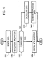
- FIG. 4 is a diagram illustrating an example of an operational flowchart of primary and secondary cards, according to an embodiment.
- Each of the primary card 110 and the secondary card 120 upon receiving data from the MME 10, performs the following operations.
- one of primary and secondary cards receives data that is transmitted from the MME 10 (in step S401), and obtains mode information from the memory (in step S402). Next, it is determined whether or not the own card is a primary card (in a primary mode), based on the obtained mode information (in step S403).
- step S403 When it is determined that the own card is a primary card (YES in step S403), SCTP processing is performed on the data received in step S401 (in step S404), and processing is ended.
- step S404 When it is determined that the own card is not a primary card (NO in step S403), the data received in step S401 is encapsulated (in step S405), and the encapsulated data is transferred to the other one of the primary and secondary cards (in step S406), and processing is ended.
- the following is an example of operational steps of a first card 110.
- the first card 110 reads out mode information 271 from a memory 270 (in step S402), and determines, in this case, that the own card (first card 110) is a primary card since the mode information 271 indicates a primary mode (in step S403). Then, the first card 110 performs SCTP processing on the received data since the first card 110 is a primary card (in step S404).
- the second card 120 reads out mode information 371 from a memory 370 (in step S402), and determines, in this case, that the own card (second card 120) is a secondary card since the mode information 371 indicates a secondary mode (in step S403). Then, the second card 120 (secondary card) encapsulates the received data (in step S405), and transfers the encapsulated data to the primary card 110 (in step S406).
- the primary card in the case, the first card 110 may be configured to perform SCTP processing on both the primary and secondary data that are transmitted from the MME 10 to the communication apparatus 100 through the two data-paths.
- FIG. 5 is a schematic diagram illustrating an example of data encapsulated by a secondary card, according to an embodiment.
- data 510 indicates secondary data that is transmitted from a MME 10 and received by the secondary card 120.
- Data 520 is obtained by encapsulating the data 510.
- the data 510 includes SCTP data 511 storing a SCTP header and a payload, an IP header 512, and a L2 header 513.
- the IP header 512 indicates that a source IP address of the data 510 (denoted by "SRC IP ADDRESS”) is a global address "C” (denoted by "GLOBAL IP C”) assigned to the MME 10, and that a destination IP address of the data 510 (denoted by "DST IP ADDRESS”) is a global address "B" (denoted by "GLOBAL IP B”) assigned to the secondary card 120.
- the L2 header 513 indicates that a source MAC address (denoted by "SRC MAC ADDRESS”) is a global address "C” (denoted by "GLOBAL MAC C”) assigned to the MME 10, and that a destination MAC address (denoted by "DST MAC ADDRESS”) is a global address "B" (denoted by "GLOBAL MAC B”) assigned to the second card 120.
- the secondary card 120 encapsulates the data 510 by removing the L2 header 513 from the data 510 and by adding an IP header 522 and a L2 header 523 to the data 510 from which the L2 header 513 has been removed, to generate the data 520. Further, the secondary card 120 inserts into the L2 header 523 an identifier indicating that the data 520 is to be transferred through a communication tunnel set through the card-to-card link between the primary and secondary cards.
- the IP header 522 indicates that a source IP address (denoted by "SRC IP ADDRESS”) is a local address "b" (denoted by "LOCAL IP b") assigned to the second card 120, and that a destination IP address (denoted by "DST IP ADDRESS”) is a local address "a" (denoted by "LOCAL IP a") assigned to the first card 110.
- the IP header 523 indicates that a source MAC address (denoted by "SRC MAC ADDRESS”) is a local address "b" (denoted by “LOCAL MAC b") assigned to the second card 120, and that a destination MAC address (denoted by "DST MAC ADDRESS”) is a local address "a” (denoted by "LOCAL MAC a") assigned to the first card 110.
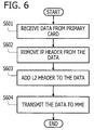
- FIG. 6 is a diagram illustrating an example of an operational flowchart of a secondary card when transmitting secondary data to another communication apparatus, according to an embodiment.
- a first card 110 (a primary card) transfers secondary data to a second card 120 (a secondary card)
- the second card 120 performs the following operations so as to transmit the received secondary data to another communication apparatus.
- the second card 120 receives secondary data transferred from a primary card of the first card 110 (in step S601), and then removes the IP header from the secondary data received in step S601 (in step S602).
- a secondary card of the second card 120 adds a L2 header to the secondary data from which the IP header has been removed in step S602 (in step S603), and then transmits to the MME 10 the secondary data to which the L2 header has been added, in step S604.
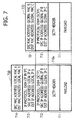
- FIG. 7 is a schematic diagram illustrating an example of data decapsulated by a secondary card, according to an embodiment.
- data 710 is data received by the secondary card 120 in step S601 of FIG. 6
- data 720 is data decapsulated by the secondary card 120 in steps S602 and S603 of FIG. 6 .
- the data 710 includes an IP encapsulated part 710a, an IP header 713, and a L2 header 714.
- the IP encapsulated part 710a which is a part encapsulated by the primary card, includes SCTP data 711 and an IP header 712, and the SCTP data 711 includes a payload and a SCTP header.
- the IP header 712 indicates that a source IP address (denoted by "SRC IP ADDRESS”) is a global address "B" (denoted by "GLOBAL IP B") assigned to the second card 120, and that a destination IP address (denoted by "DST IP ADDRESS”) is a global address "C” (denoted by "GLOBAL IP C”) assigned to the MME 10.
- the IP header 713 indicates that a source IP address (denoted by "SRC IP ADDRESS”) is a local address "a” (denoted by "LOCAL IP a") assigned to the first card 110, and that a destination IP address (denoted by "DST IP ADDRESS”) is a local address "b" (denoted by "LOCAL IP b") assigned to the second card 120.
- SRC IP ADDRESS source IP address
- DST IP ADDRESS local address assigned to the second card 120.
- the L2 header 714 indicates that a source MAC address (denoted by "SRC MAC ADDRESS”) is a local address "a” (denoted by “LOCAL MAC a") assigned to the first card 110, and that a destination MAC address (denoted by "DST MAC ADDRESS”) is a local address "b" (denoted by "LOCAL MAC b") assigned to the second card 120.
- the second card 120 performs decapsulation by removing the IP header 713 from the data 710 and adding the L2 header 721 in replacement of the L2 header 714, so as to generate the data 720.
- the L2 header 721 indicates that a source MAC address (denoted by "SRC MAC ADDRESS”) is a global address "B" (denoted by "GLOBAL MAC B") assigned to the second card 120, and that a destination MAC address (denoted by "DST MAC ADDRESS”) is a global address "C" (denoted by "GLOBAL MAC C”) assigned to the MME 10.
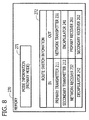
- FIG. 8 is a diagram illustrating an example of information stored in a memory of a primary card, according to an embodiment.
- the mode information 271 which is stored in the memory 270 of the first card 110, indicates a primary mode, meaning that the first card 110 is a primary card.
- the route switch information 272 of the memory 270 stores information on route connections controlled by the route switch 220, in which input interface information (stored in an "IN" column) of the route switch 220 is associated with output interface information (stored in an "OUT" column) of the route switch 220.
- an input interface connected to the primary transmitter 211 (stored in the "IN” column) is associated with an output interface connected to the network transmitter 231 (stored in the "OUT” column), and an interface connected to the secondary transmitter 212 (stored in the "IN” column) is associated with an output interface connected to the encapsulator 241 (stored in the "OUT” column).
- an input interface connected to the network receiver 232 (stored in the "IN” column) is associated with an output interface connected to the primary receiver 261 (stored in the "OUT” column), and an input interface connected to the decapsulator 242 (stored in the "IN” column) is associated with an output interface connected to the secondary receiver 262 (stored in the "OUT” column).
- the route switch 220 of the primary card 110 may be configured to perform route switching as depicted in FIG. 3 by reading out the route switch information 272 from the memory 270 and switching a route connection via which data is to be conveyed in accordance with the route switch information 272.
- FIG. 9 is a diagram illustrating an example of information stored in a memory of a secondary card, according to an embodiment.
- the mode information 371 which is stored in the memory 370 of the second card 120, is indicating a secondary mode, meaning that the second card 120 is a secondary card.
- the route switch information 372 of the memory 370 stores information on route connections of the route switch 320, in which input interface information (stored in an "IN" column) of the route switch 320 is associated with output interface information (stored in an "OUT" column) of the route switch 320.
- an input interface connected to the network receiver 332 (stored in the "IN” column) is associated with an output interface connected to the encapsulator 241 (stored in the "OUT” column), and an interface connected to the decapsulator 342 (stored in "IN” column) is associated with the network transmitter 331 (stored in the "OUT” column).
- the route switch 320 may be configured to perform route switching as depicted in FIG. 3 by reading out the route switch information 372 from the memory 370 and switching a route connection via which data is to be conveyed in accordance with the route switch information 372.
- primary and secondary transmission-routes may be set by the primary and secondary cards.
- FIG. 10 is a schematic diagram illustrating an operational example of a communication apparatus when a failure has occurred in a primary card, according to an embodiment.
- the protocol handler in the case, the SCTP handler 113 of the primary card 110 is performing transmission of primary data between the primary card 110 and the MME 10 through a primary data-path established along a primary transmission-route including a first route 11, while performing transmission of secondary data between the primary card 110 and the MME 10 through a secondary data-path established along a secondary transmission-route including the card-to-card link (in the case, a L2 switch 130) and a second route 12.
- the access controller 121 of the secondary card 120 detects a failure that has occurred in the primary card 110. The method for detecting a failure will be described later, for example, with reference to FIGs. 15 and 16 .
- the second card 120 Upon detecting a failure in the first card 110 (a primary card), the second card 120 is determined to be a new primary card. Then the access controller 121 of the second card 120 (a secondary card) changes the operating state thereof from a standby state to an active state, and invokes the signal processor 122 of the second card 120 which activates the protocol handler (in the case, the SCTP handler 123) included therein.
- the new primary card of second card 120 sets a new primary transmission-route connecting the SCTP handler 123, a NIC 124, and a second route 12. Thereafter, the signal processor 122 of the new primary card (the second card 120) starts a communication with the MME 10 without using a multi-homing method.
- the signal processor 122 of the new primary card 120 establishes a new primary data-path between the new primary card 120 and the MME 10 along a new primary transmission-route, and performs transmission of primary data through the new primary data-path.
- the new primary card 120 does not perform transmission of secondary data due to the failure in the first card 110, processes such as encapsulation and decapsulation which are needed for transferring secondary data between the first and second cards are not performed.
- the communication apparatus 100 is able to maintain the communication with the MME 10 even if a failure has occurred in the existing primary card 110 of the communication apparatus 100.
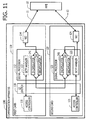
- FIG. 11 is a schematic diagram illustrating an operational example of a communication apparatus when the failure has recovered, according to an embodiment.
- the failure in the first card 110 depicted in FIG. 10 has recovered.
- the access controller 121 of the second card 120 (the new primary card) remains in the active state even when the failure in the first card 110 has recovered. Therefore, the access controller 121 becomes a main controller for controlling the whole communication apparatus 100.
- the first card 110 which was not being operated due to the failure, is determined to be a secondary card, and the access controller 111 of the first card 110 changes the operational state thereof into a standby state.
- the access controller 121 of the second card 120 sets a secondary transmission-route for establishing a secondary data-path.
- the secondary transmission-route is set so as to connect the SCTP handler 123, the encapsulator 341 and the decapsulator 342 of the signal processor 122, the L2 switch 130 (a card-to-card link), the encapsulator 241 and the decapsulator 242 of the signal processor 112, the NIC 114, and the first route 11 connected to the first card 110.
- the second card 120 (the new primary card) performs a multi-homing communication with the MME 10 by establishing a secondary data-path along the secondary transmission-route, and by transmitting secondary data through the established secondary data-path.
- the SCTP handler 123 (the protocol handler) of the second card 120 establishes a secondary data-path along the secondary transmission-route, and performs a multi-homing communication with the MME 10 by transmitting the primary and secondary data through the existing primary data-path established along the existing primary transmission-route, and through the secondary data-path established along the newly-set secondary transmission-route, respectively.
- the SCTP handler 123 transmits primary data to the MME 10 using, as a source address thereof, a global address "B" assigned to the second card 120. Further, the signal processor 122 of the second card 120 encapsulates secondary data, and transfers the encapsulated secondary data to the first card 110 via the L2 switch 130. In the case, the signal processor 122 may be configured to transfer secondary data to the first card 110 using, as a destination address thereof, a local address "a" assigned to the first card 110.
- the SCTP handler 123 of the second card 120 receives primary data that is transmitted from the MME 10 through the existing primary data-path.
- the signal processor 122 of the second card 120 may be configured to receive primary data that is transmitted from the MME 10 through the second route 12 using, as a destination address, a global address "B" assigned to the second card 120.
- the SCTP handler 123 receives secondary data through the secondary data-path.
- the signal processor 122 may be configured to receive secondary data that is transferred from the first card 110 using, as a destination address thereof, a local address "b" assigned to the second card 120.
- the SCTP handler 113 of the first card 110 is not operated since the access controller 111 of the first card 110 is being in a standby state, that is, the first card 110 is a secondary card.
- the signal processor 112 of the first card 110 receives secondary data that is encapsulated by the second card 120 and transferred from the second card 120, and decapsulates the received secondary data.
- the signal processor 112 may be configured to receive secondary data that is transferred from the second card 120 via the L2 switch 130 using, as a destination address, a local address "a" assigned to the first card 110.
- the signal processor 112 transmits the decapsulated secondary data to the MME 10 via the NIC 114 through the first route 11.
- the signal processor 112 may be configured to transmit the decapsulated secondary data to the MME 10 using, as a source address, a global address "A" assigned to the first card 110.
- the signal processor 112 of the first card 110 receives secondary data transmitted from the MME 10 through the secondary data-path established along the newly-set secondary transmission-route.
- the signal processor 112 may be configured to receive secondary data that is transmitted from the MME 10 using, as a destination address, a global address "A" assigned to the first card 110.
- the signal processor 112 of the first card 110 encapsulates the received secondary data and transfers the encapsulated secondary data to the second card 120 via the L2 switch 130.
- the signal processor 112 may be configured to transfer the encapsulated secondary data to the second card 120 using, as a destination address, a local address "b" assigned to the second card 120.
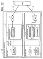
- FIG. 12 is a schematic diagram illustrating an example of an operation of a communication apparatus when a failure has occurred in a secondary card, according to an embodiment.
- a first card 110 is a primary card and a second card 120 is a secondary card.
- the access controller 111 of the first card 110 detects the failure in the second card 120 (a secondary card). The method for detecting a failure will be described later, for example, with reference to FIGs. 15 and 16 .
- the SCTP handler 113 of the signal processor 112 starts a communication with the MME 10 without using a multi-homing method.
- the SCTP handler 113 communicates with the MME 10 through the existing primary data-path established along the existing primary transmission-route that includes the NIC 114 and the first route 11.
- processes such as encapsulation or decapsulation required for transmitting secondary data are not performed since the second card 120 is not operated properly due to the failure occurrence.
- the communication apparatus 100 is able to maintain a communication with the MME 10 through the existing primary data-path even though a failure has occurred in the secondary card (in the case, the second card 120).
- the access controller 111 of the first card 110 detects the recovery of the failure in the second card 120, and then the SCTP handler 113 of the first card 110 starts a multi-homing communication with the MME 10.
- the communication apparatus 100 since the operation of the communication apparatus 100 is similar to that depicted in FIG. 1 , the detailed description thereof is skipped here.
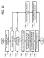
- FIG. 13 is a diagram illustrating an example of an operational flowchart for starting up one of first and second cards, according to an embodiment.
- Each of the first card 110 and the second card 120 performs the following operations at the time of startup.
- a value indicating an "out of service” (OOS) mode is set to mode information 271 or 371 (in step S1301).
- OOS output of service
- it is determined whether or not the own card has the smallest ID number among all the cards within the communication apparatus 100 in step S1303).
- the own card turns into a primary card (in step S1304), and then a value indicating a primary mode is set to the mode information thereof (in step S1305).
- a value indicating a secondary mode is set to the mode information of the other card within the communication apparatus 100 (in step S1306), and then a communication service (for example, a communication with the MME 10) provided by the signal processor of the own card (the signal processor 112 or the signal processor 122) is started (in step S1307).
- a communication service for example, a communication with the MME 10
- step S1302 When there exists a primary card within the communication apparatus 100 (YES in step S1302) or when the own card does not have the smallest ID number among all the cards within the communication apparatus 100 (NO in step S1303), the own card turns into a secondary card (in step S1308), and starts to monitor operating states of the other card (for example, whether the other card is alive or no) within the communication apparatus 100 (in step S1309).
- the number "1" may be assigned to the first card 110 and the number "2" may be assigned to the second card 120.
- the first card 110 determines that the own card has the smallest ID number among all the cards within the communication apparatus 100 (YES in step S1303)
- the second card 120 determines that the own card does not have the smallest ID number among all the cards within the communication apparatus 100 (NO in step S1303).
- a value indicating an OOS (Out Of Service) mode is set to the mode information 271 in step S1301. Further, in step S1302, the first card 110 proceeds to step S1303 when it is determined that the second card 120 is not a primary card, or proceeds to step S1308 when it is determined that the second card 120 is a primary card.
- OOS Out Of Service
- the first card 110 in step S1305, sets a value indicating a primary mode to the mode information 271 in the memory 270 of the first card 110, and, in step S1306, the first card 110 sets a value indicating a secondary mode to the mode information 371 in the memory 370 of the second card 120.
- the second card 120 sets a value indicating an OOS mode to the mode information 371 in step S1301. Further, in step S1302, the second card 120 proceeds to step S1303 when it is determined that the first card 110 is not a primary card (for example, the first card 110 being a secondary card), and proceeds to step S1308 when it is determined that the first card 110 is a primary card.
- step S1305 the second card 120 sets a value indicating a primary mode to the mode information 371 in the memory 370 of the second card 120, and, in step S1306, the second card 120 sets a value indicating a secondary mode to the mode information 271 in the memory 270 of the first card 110.
- FIG. 14 is a schematic diagram illustrating an example of a procedure for setting a value to mode information when a first card starts up, according to an embodiment.
- FIG. 14 represents parts of the communication apparatus 100 that are relevant to the procedure for setting a value to the mode information.
- the access controller 111 of the first card 110 sets a value indicating a primary mode to the mode information 271 in the memory 270 by outputting a control signal 1411 to a setting part 280 of the first card 110 when executing the step S1305 of FIG. 13 .
- the access controller 111 of the first card 110 sets a value indicating a secondary mode to the mode information 371 in the memory 370 by outputting a control signal 1412 to the setting part 380 of the second card 120 when executing the step S1306 of FIG. 13 .
- the access controller 111 of the first card may be configured to set values to both the mode information 271 and 371 by controlling both the setting part 280 of the first card 110 and the setting part 380 of the second card 120.
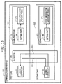
- FIG. 15 is a schematic diagram illustrating an operation example for monitoring operating states of first and second cards by an access controller, according to an embodiment.
- operating states for example, whether a card is alive or not
- heart beat signals 1511 and 1512 are exchanged between the access controllers 111 and 121 via the L2 switch 130.
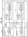
- FIG. 16 is a schematic diagram illustrating an operation example for monitoring operating states of first and second cards by an access controller, according to an embodiment.
- a heart beat signal 1512 which is sent from the access controller 111 to the access controller 121, failed to reach the access controller 121 due to a failure occurrence in the access controller 111.
- the access controller 121 of the second card 120 may be configured to determine a failure occurrence in the access controller 111 of the first card 110 when the access controller 121 has not received the heart beat signal 1512 from the access controller 111 for a given time period.
- the accesses controller 121 of the second card 120 shifts its operating state from a standby state to an active state, and set a value indicating a secondary mode to the mode information 271 of the first card 110 by sending a control signal 1611 to the setting part 280 of the first card 110 via thy L2 switch 130. Further, the accesses controller 121 sets a value indicating a primary mode to the mode information 371 of the second card 120 by sending a control signal 1612 to the setting part 380 of the second card 120.
- the access controller 121 of the second card 120 sets primary and secondary transmission-routes by controlling the signal processor 122, and invokes the SCTP handler 123 of the second card 120.
- a second route 12 connected to the second card 120 is used as a part of a primary transmission-route
- a first route 11 connected to the first card 110 is used as a part of a secondary transmission-route.
- primary and secondary data-paths are established along the primary and secondary transmission-routes, respectively.
- operation for a multi-homing communication is similar to that described in FIG. 11 , and the detailed description about the operation is omitted here.
- the first card 110 when a failure has occurred in the first card 110 such that the access controller 121 of the second card 120 is not able to control the signal processor 112 of the first card 110, the first card 110 may be configured to autonomously shift its operating mode to an OOS mode, thereby setting a value indicting an OOS mode to the mode information 271.
- the secondary transmission-route and the secondary data-path established along the secondary transmission-route may be broken. Accordingly, a multi-homing communication with the MME 10 may not be performed.
- FIG. 17 is a schematic diagram illustrating an operation example for maintaining a first card, according to an embodiment.
- the first card 110 is operated as a primary card and the second card 120 is operated as a secondary card.
- the access controller 111 of the first card 110 shifts its operating state from an active state to an OOS state, and sends a switch signal 1710 to the access controller 121 of the second card 120 via the L2 switch 130.
- the access controller 121 of the second card 120 Upon receiving the switch signal 1710 from the access controller 111, the access controller 121 of the second card 120 shifts its operating state from a standby state to an active state. Then, the access controller 121 of the second card 120 sets a value indicating a secondary mode to the mode information 271 of the first card 110 by sending a control signal 1721 to the setting part 280 of the first card 110 via the L2 switch 130, and sets a value indicating a primary mode to the mode information 371 of the second card 120 card by sending a control signal 1722 to the setting part 380 of the second card, as depicted in FIG. 17 .
- the access controller 121 of the second card 120 sets primary and secondary transmission-routes by controlling the signal processors 112 and 122, and activates the SCTP handler 123 of the second card 120, so as to perform a multi-homing communication.
- a second route 12 connected to the second card 120 is used as a part of the primary transmission-route
- a first route 11 connected to the first card 110 is used as a part of the secondary transmission-route
- primary and secondary paths are established along the primary and secondary transmission-routes, respectively.
- the operation for the multi-homing communication is similar to that described in FIG. 11 , and the detailed description about the operation is skipped here.
- FIG. 18 is a schematic diagram illustrating an operation example for monitoring operating states of first and second cards by a setting part, according to an embodiment.
- the setting part 280 of the first card 110 monitors the operating state (for example, whether alive or not) of the access controller 111, by sending a health check signal 1811 to the access controller 111 and monitoring reception of a response to the health check signal 1811 from the access controller 111.
- the setting part 280 monitors the operating state of the access controller 121 of the second card 120, by sending a health check signal 1812 to the access controller 121 and monitoring reception of a response to the health check signal 1812 from the access controller 121.
- the setting part 380 of the second card 120 monitors the operating state (whether alive or not) of the access controller 121 of the second card 120, by sending a health check signal 1821 to the access controller 121 and monitoring reception of a response to the health check signal 1821 from the access controller 121. Further, the setting part 380 monitors an operating state (whether alive or not) for the access controller 111 of the first card 110, by sending a health check signal 1822 to the access controller 111 and monitoring reception of a response to the health check signal 1822 from the access controller 111.
- health check signals and responses thereto are transmitted via the L2 switch 130 between the first and second cards.
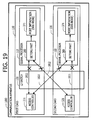
- FIG. 19 is a schematic diagram illustrating an operation example for monitoring operating states of first and second cards by a setting part, according to an embodiment.
- the setting part 280 determines that a failure has occurred in both the access controllers 111 and 121 when a response to a health check signal has not been received from each of the access controllers 111 and 121 for a given time period.
- the setting part 280 Upon determining that failures have occurred in both the access controllers 111 and 121, the setting part 280 sets a value indicating an OOS mode to the mode information 271, as depicted in FIG. 19 .
- the setting part 380 determines that a failure has occurred in both the access controllers 111 and 121 when a response to a health check signal is not received from each of the access controllers 111 and 121 for a given time period. Then the setting part 380 sets a value indicating an OOS mode to the mode information 371, as depicted in FIG. 19 .
- a value indicating a secondary mode may be set to both the mode information 271 and 371 since none of the access controller 111 and 121 are operated normally.
- data received from the MME 10 by the first card 110 may be transferred to the second card 120 and may be returned back to the MME 10 by the second card 120.
- data received from the MME 10 by the second card 120 may be transferred to the first card 110 and may be returned back to the MME 10 by the first card 120.
- the route switch 220 of the signal processor 112 may be configured to discard data received from the primary transmitter 211 when a value indicating an OOS mode is being set to the mode information 271.
- the route switch 320 of the signal processor 122 may be configured to discard data that was received from the network receiver 332 when a value indicating an OOS mode is being set to the mode information 371.
- the failure When a failure has occurred in one of the access controller 111 or 121, the failure may be detected by the other one of the access controllers 111 or 121 which is being operated in a active state. Therefore, data received from the MME 10 may be processed properly.
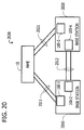
- FIG. 20 is a diagram illustrating a configuration example of a communication system, according to an embodiment.
- a 3G communication system is depicted as a communication system 2000 according to an embodiment.
- the communication system 2000 may be configured to include a MME 10, base stations 2010 and 2020.
- the base station 2010 may be configured to include a communication apparatus 100-1 for performing a multi-homing communication with the MME 10 through a pair of data-paths (denoted by "2011" in FIG. 20 ). Further, the base station 2010 may be configured to include a communication apparatus 100-2 for performing a multi-homing communication with the base station 2020 through a pair of data-paths (denoted by "2012" in FIG. 20 ).
- the base station 2020 may be configured to include a communication apparatus 100-3 for performing a multi-homing communication with the MME 10 through a pair of data-paths (denoted by "2021" in FIG. 20 ). Further, the base station 2020 may be configured to include a communication apparatus 100-4 for performing a multi-homing communication with the base station 2010 through a pair of data-paths (denoted by "2012" in FIG. 20 ).
- multi-homing communications may be performed among communication devices, such as the MME 10, the base station 2010, and the base station 2020, by applying a communication apparatus 100 of the present invention, to each of the base stations 2010 and 2020.
- the communication apparatus 100 of the present invention may be configured to communicate with not only a MME 10 but also other communication devices such as base stations 2010 and 2020. It is also possible to perform a multi-homing communication between base stations 2010 and 2020 by equipping each of the base stations 2010 and 2020 with a communication apparatus 100 of the present invention.
- a communication tunnel may be formed between a primary card and a secondary card.
- the communication apparatus 100 transmits primary data to be transmitted through a primary data-path, from the primary card through one of first and second routes connected to the primary card. Further, the communication apparatus 100 transmits secondary data to be transmitted through a secondary data-path, from the primary card by transferring the secondary data from the primary card to the secondary card via the communication tunnel so that the secondary data is transmitted from the secondary card through the other one of the first and second routes connected to the secondary card.
- a multi-homing communication may be performed with improved reliability by using a redundant configuration of the primary and secondary cards.
- a protocol handler such as a SCTP handler is not activated, reducing electrical power consumptions.
- Primary and secondary cards form a communication tunnel between the primary and secondary cards by transferring data to each other using a local address assigned to each of the primary and secondary cards. Therefore, source and destination addresses of the transferred data are fixed, allowing the communication apparatus to transfer data between the primary and secondary cards without implementing a complicated routing control part such as a NAT or a NATP. This also allows a stable and high-speed data transfer, and the size of a communication apparatus may be reduced.
- a communication apparatus allows a multi-homing communication with improved reliability by using a redundant configuration of primary and secondary cards.
- FIG. 1 a configuration in which a communication apparatus 100 communicates with a MME 10 is described.
- communication devices with which the communication apparatus 100 communicates may be a base station (as depicted in FIG. 20 ) or communication devices other than a base station.
Landscapes
- Engineering & Computer Science (AREA)
- Computer Networks & Wireless Communication (AREA)
- Signal Processing (AREA)
- Data Exchanges In Wide-Area Networks (AREA)
- Telephonic Communication Services (AREA)
Description
- The present invention relates to a communication apparatus for transmitting data through a plurality of data-paths.
- As typified by S3G (Super 3G), a communication system in which base stations are connected to each other through multiple data-paths by using a multi-homing method, has been put into practical use. For example, Japanese Laid-Open Patent Application Publication No.
2000-209278 2006-279467 - According to a multi-homing method, a communication apparatus, such as a base station, is typically configured to include a card for handling SCTP (Stream Control Transmission Protocol) which is a protocol corresponding to a transmission layer. The card may have, for example, two link ports each connected to a link port of another communication apparatus with which the base station communicates. The card may be configured to include a SCTP handler that terminates a SCTP signal. In the case, one of the two link ports is used for a primary data-path and the other one for a secondary data-path where a global address is assigned to each of the two link ports. Data is transmitted and received through the primary data-path under normal conditions, and the secondary data-path is used as an alternate path when the primary data-path is disconnected, for example, due to a failure. Here, it is also possible to distribute a communication load by using both the primary and secondary data-paths concurrently.
- However, in the case where a card has only one link port for communicating with another communication apparatus, the above mentioned multi-homing communication may not be attained. Therefore, to perform a multi-homing communication, each of primary and secondary data-paths needs to be accommodated in a different card. Further, a communication apparatus, such as a base station, may be configured to include a redundant card so as to keep communication even if a failure has occurred in some cards. Adopting a redundant card requires each of primary and secondary data-paths to be accommodated in a different card. However, if each of primary and secondary data-paths is accommodated in a different card, a multi-homing method may not be applied since the primary and secondary data-paths are handled independently by each of SCTP handlers of two different cards.
- In order to avoid the above problem, it may be possible to configure an access controller of the card, which is normally configured to provide services such as call processing, to perform a multi-homing communication. However, this causes another problem that the load of the access controller becomes higher, thereby exerting an adverse effect on providing the above-mentioned services such as call processing.
- Further, in the case of a card having only one link port for communicating with another communication apparatus, the card may be assigned with one global address and one local address. A multi-homing method according to SCTP uses two global addresses each assigned to one of primary and secondary data-paths. In this case, when a setting for a multi-homing communication has been done within the card, the SCTP handler of the card may try to start a communication with another communication apparatus using both the global address and the local address which are assigned to the card. However, the communication using the local address fails since the local address is effective only within the communication apparatus. As a result, a multi-homing communication with another communication apparatus may not be performed. This case is also undesirable from the aspect of security because the local address for the card of the communication apparatus may flow out into the network.
WO 02/096035 - Accordingly, it is an object In one aspect of the invention to perform a multi-homing communication with improving the reliability using a redundant card configuration.
- According to an aspect of the invention, there is provided a communication apparatus for transmitting data through a plurality of data-paths as defined in
claim 1. Preferred features are defined In the dependent claims. - The object and advantages of the invention will be realized and attained by means of the elements and combinations particularly pointed out in the claims.
- It is to be understood that both the foregoing general description and following detailed description are exemplary and explanatory and are not restrictive of the invention, as claimed.
-
FIG. 1 is a diagram illustrating a configuration example of a communication apparatus, according to an embodiment; -
FIG. 2 is a block diagram illustrating a configuration example of a signal processor of a primary card, according to an embodiment; -
FIG. 3 is a block diagram illustrating a configuration example of a signal processor of a secondary card, according to an embodiment; -
FIG. 4 is a diagram illustrating an example of an operational flowchart of primary and secondary cards, according to an embodiment; -
FIG. 5 is a schematic diagram illustrating an example of data encapsulated by a secondary card, according to an embodiment; -
FIG. 6 is a diagram illustrating an example of an operational flowchart of a secondary card when transmitting secondary data to another communication apparatus, according to an embodiment; -
FIG. 7 is a schematic diagram illustrating an example of data decapsulated by a secondary card, according to an embodiment; -
FIG. 8 is a diagram illustrating an example of information stored in a memory of a primary card, according to an embodiment; -
FIG. 9 is a diagram illustrating an example of information stored in a memory of a secondary card, according to an embodiment; -
FIG. 10 is a schematic diagram illustrating an operational example of a communication apparatus when a failure has occurred in a primary card, according to an embodiment; -
FIG. 11 is a schematic diagram illustrating an operational example of a communication apparatus when the failure has recovered, according to an embodiment; -
FIG. 12 is a schematic diagram illustrating an example of an operation of a communication apparatus when a failure has occurred in a secondary card, according to an embodiment; -
FIG. 13 is a diagram illustrating an example of an operational flowchart for starting up one of first and second cards, according to an embodiment; -
FIG. 14 is a schematic diagram illustrating an example of a procedure for setting a value to mode information when a first card starts up, according to an embodiment; -
FIG. 15 is a schematic diagram illustrating an operation example for monitoring operating states of first and second cards by an access controller, according to an embodiment; -
FIG. 16 is a schematic diagram illustrating an operation example for monitoring operating states of first and second cards by an access controller, according to an embodiment; -
FIG. 17 is a schematic diagram illustrating an operation example for maintaining a first card, according to an embodiment; -
FIG. 18 is a schematic diagram illustrating an operation example for monitoring operating states of first and second cards by a setting part, according to an embodiment; -
FIG. 19 is a schematic diagram illustrating an operation example for monitoring operating states of first and second cards by a setting part, according to an embodiment; and -
FIG. 20 is a diagram illustrating a configuration example of a communication system, according to an embodiment. - According to an embodiment, a communication tunnel is formed through a card-to-card link between first and second cards. This allows one of the first and second cards to perform a communication with another communication apparatus through the other one of the first and second cards using the communication tunnel, and a multi-homing communication using a plurality of data-paths can be performed with a redundant configuration of the first and second cards.
-
FIG. 1 is a diagram illustrating a configuration example of a communication apparatus, according to an embodiment. - A
communication apparatus 100 may be, for example, an evolutional Node B (eNB) that communicates with a higher level system. As depicted inFIG. 1 , thecommunication apparatus 100 may be configured to include afirst card 110, asecond card 120, and aL2 switch 130. The L2 switch 130 functions as a card-to-card link between the first and second cards. Thecommunication apparatus 100 performs transmission of data between thecommunication apparatus 100 and another communication apparatus (for example, aMME 10 as depicted inFIG. 1 ) through afirst route 11 connected to thefirst card 110 and a second route connected to thesecond card 120. - A pair of one global address and one local address are assigned to each of the first and
second cards first card 110 and let "B" be a global address assigned to thesecond card 120. - The
first card 110 includes, for example, anaccess controller 111, asignal processor 112, and a NIC (network interface card) 114. Thesignal processor 112 may be configured to include, for example, aSCTP handler 113 as a protocol handler, anencapsulator 241, anddecapsulator 242. Thesecond card 120 includes, for example, anaccess controller 121, asignal processor 122, and aNIC 124. Thesignal processor 122 may be configured to include, for example, aSCTP handler 123 as a protocol handler, anencapsulator 341, anddecapsulator 342. Here, thefirst card 110 and thesecond card 120 communicate with each other via the L2 SWITCH 130 (Layer 2 Switch) that functions as a card-to-card link between the first and second cards. - The
access controller 111 is a controller for controlling thefirst card 110, and theaccess controller 121 is a controller for controlling thesecond card 120. Under normal conditions, one of theaccess controllers access controller 111 of thefirst card 110 is in an active state and theaccess controller 121 of thesecond card 120 is in a standby state, in other words, thefirst card 110 is a primary card and thesecond card 120 is a secondary card. - The
access controller 111 in an active state operates as a main controller for controlling both the first and second cards. That is, in this case, thefirst card 110 including theaccess controller 111 of an active state is operated as a primary card that controls both the first and second cards. Theaccess controller 111 of the first card 110 (the primary card) may provide services, such as call control service and a handover service, in cooperation with aSCTP handler 113 of thefirst card 110. These services may be provided, for example, in accordance with the 3GPP/LTE. - The
access controller 121 of the second card 120 (the secondary card), which is at present in a standby state, remains in the standby state until theaccess controller 111, which is at present in an active state, turns into an OOS (Out Of Service) state, for example, due to a failure or a maintenance operation. When theaccess controller 111 of theprimary card 110 turns into an OOS state, theaccess controller 121 of thesecondary card 120 shifts to an active state, in other words, thesecond card 120 becomes a primary card that controls both the first and second cards. - The
signal processor 112 of thefirst card 110 may be, for example, a NWP (Network Processor) having a security function. Thesignal processor 112 includes aprotocol handler 113 for handling a given protocol that establishes a plurality of data-paths and performs a transmission of data through the established plurality of data-paths. In the example of theFIG. 1 , a SCTP is used as the given protocol, and aSCTP handler 113 that terminates the SCTP is depicted as an example of a protocol handler. TheSCTP handler 113 performs a multi-homing communication with theMME 10 using afirst route 11 connected to thefirst card 110 and asecond route 12 connected to thesecond card 120. A multi-homing communication requires two data-paths each established along a different transmission-route. One of the two data-paths is used for transmitting primary data and hereinafter referred to as "a primary data-path". The other one of the two data-paths is used as a backup data-path for the primary data-path or may be used for transmitting secondary data, and hereinafter referred to as "a secondary data-path". - In the example depicted in
FIG. 1 , the primary data-path is established along a primary transmission-route that is set to connect theSCTP handler 113, aNIC 114, and afirst route 11 connected to thefirst card 120. Further, the secondary data-path is established along a secondary transmission-route that is set to connect theSCTP handler 113, theencapsulator 241 and thedecapsulator 242 of thesignal processor 112, the L2 switch 130 (a card-to-card link), theencapsulator 341 and thedecapsulator 342 of thesignal processor 122, aNIC 124, and asecond route 12 connected to thesecond card 120. - In the example of
FIG. 1 , when establishing two data-paths from theSCTP handler 113 to theMME 10, theSCTP handler 113 issues two connection requests (INIT) to theMME 10, notifying theMME 10 of the global address "A" assigned to thefirst card 110 and the global address "B" assigned to thesecond card 120. - Thereafter, upon receiving an acknowledge (ACK) from the
MME 10, theSCTP handler 113 of thefirst card 110 starts a multi-homing communication withMME 10. TheSCTP handler 113 monitors each state of the primary and secondary data-paths, and determines one of the primary and secondary data-paths to be a data-path through which primary data is to be transmitted. For example, theSCTP handler 113 transmits primary data through the primary data-path under normal conditions, and determines the existing secondary data-path to be a new primary data-path when a failure has occurred in the existing primary data-path so as to transmit the primary data through the new primary data-path. - The
primary card 110 sets a primary transmission-route through which a primary data-path is to be established, and sets a secondary transmission-route through which a secondary data-path is to be established. In the case, the primary data-route is set as a route, from theSCTP handler 113 to theMME 10, that passes through theNIC 114 and the first-route 11 connected to thefirst card 110, as mentioned above. The secondary transmission-route is set as a route, from theSCTP handler 113 to theMME 10, that passes through theL2 switch 130, thesignal processor 122, and theNIC 124, as mentioned above. - The
SCTP handler 113 of the first card 110 (a primary card) sends primary data to theMME 10 through the primary data-path that is established along the primary transmission-route. For example, thesignal processor 112 of thefirst card 110 transmits the primary data to theMME 10 through the primary data-path using, as a source address of the primary data, the global address "A" assigned to thefirst card 110. - The
SCTP handler 113 of the first card 110 (a primary card) sends secondary data to theMME 10 through the secondary data-path that is established along the secondary transmission-route. For example, thesignal processor 112 of thefirst card 110 encapsulates the secondary data, and transfers the encapsulated secondary data to the second card 120 (a secondary card) via the card-to-card link (in the case, the L2 switch 130). In the case, thesignal processor 112 of thefirst card 110 may be configured to transfer the encapsulated secondary data to thesecondary card 120 using, as a destination address of the secondary data, the local address "b" assigned to thesecond card 120. Upon receiving the encapsulated secondary data from thefirst card 110, thesignal processor 122 of thesecond card 120 decapsulates the received encapsulated secondary data. In the case, thesignal processor 122 of thesecond card 120 may be configured to receive secondary data that is transferred from thefirst card 110 using, as a destination address of the secondary data, the local address "b" assigned to thesecond card 120. Next,signal processor 122 of thesecond card 120 transmits the decapsulated secondary data, that sis, the original secondary data to theMME 10 viaNIC 124 through thesecond route 12 connected to thesecond card 120. In the case, thesignal processor 122 may be configured to transmit the secondary data using, as a source address of the secondary data, the global address "B" assigned to thesecond card 120. - The
SCTP handler 113 of the first card 110 (a primary card) receives primary data that is transmitted fromMME 10 through the primary data-path. In the case, thesignal processor 112 may be configured to receive the primary data using, as a destination address of the primary data, the global address "A" assigned to thefirst card 110. - The
SCTP handler 113 of the first card 110 (a primary card) receives secondary data that is transmitted fromMME 10 through the secondary data-path. For example, thesignal processor 122 of thesecond card 120 receives secondary data that is transmitted fromMME 10 through thesecond route 12 connected to thesecond card 120. In the case, thesignal processor 122 may be configured to receive the secondary data using, as a destination address of the secondary data, the global address "B" assigned to thesecond card 120. Next, thesignal processor 122 encapsulates the received secondary data, and transfer the encapsulated secondary data to thefirst card 110 via the card-to-card link (the L2 switch 130). In the case, thesignal processer 122 may be configured to transfer the encapsulated secondary data to thefirst card 110 using, as a destination address of the secondary data, the local address "a" assigned to thefirst card 110. Upon receiving the encapsulated secondary data from thesecond card 120, thesignal processor 112 of thefirst card 110 decapsulates the encapsulated secondary data. Next, the decapsulated secondary data, that is, the original secondary data is sent to theSCTP handler 113. In the case, thesignal processor 112 of thefirst card 110 may be configured to receive secondary data that is transferred from thesecond card 120 using, as a destination address of the secondary data, the local address "a" assigned to thefirst card 110. - A
signal processor 122 of thesecond card 120 is, for example, a NWP having a security function. Thesignal processor 122 includes aSCTP handler 123 that terminates SCTP. In the example depicted inFIG. 1 , theSCTP handler 123 of thesecond card 120 is not activated, as depicted with dotted lines inFIG. 1 , since theaccess controller 121 of thesecond card 120 is in a standby state, in other words, thesecond card 120 is a secondary card. - As mentioned above, the
L2 switch 130 functions as a card-to-card link through which a communication tunnel is formed so that secondary data is transferred between the first card 110 (a primary card) and the second card 120 (a secondary card). Thefirst card 110 and thesecond card 120 transfer the encapsulated secondary data to each other via the communication tunnel formed through theL2 switch 130. According to the way mentioned above, data can be transferred between the first and second cards more efficiently than the case where NAT (Network Address Translation) or NAPT (Network Address Port Translation) are employed. - Further, as mentioned above, the
primary card 110 performs a transmission of primary data between theprimary card 110 and another communication apparatus (for example, the MME 10) through a primary data-path that is established along the primary transmission-route. At the same time, theprimary card 110 performs a transmission of secondary data between theprimary card 110 and another communication apparatus (for example, the MME 10) through a secondary data-path that is established along the secondary transmission-route. The secondary transmission-route may be set as a transmission-route from the protocol handler of the primary card (for example, the SCTP handler 113) to another communication apparatus (for example, the MME 10) that passes through a card-to-card link (for example, the L2 switch 130), thesecondary card 120, and asecond route 12 connected to thesecondary card 120. Thus, thecommunication apparatus 100 may be configured to concurrently transmit both primary and secondary data between a communication apparatus and another communication apparatus, using a plurality of data-paths: a primary data-path and a secondary data-path. - In the example depicted in
FIG. 1 , aMME 10 indicates a Mobility Management Entity (MME) that is a node positioned at a higher level than a base station (such as eNB) in a hierarchical network. TheMME 10 performs a mobility control, such as paging and managing areas in which a location of a terminal is to be registered. In the case, for example, two global addresses "C" and "D" are assigned toMME 10 in order to transmit primary and secondary data between thecommunication apparatus 100 and theMME 10 through two data-paths. - From the view point of the
MME 10, thecommunication apparatus 100 has two global addresses: "A" and "B". In the case, theMME 10 can transmit primary data to thecommunication apparatus 100 through primary data-path using as a destination address the global address "A" assigned to theprimary card 110, and transmit the secondary data to thecommunication apparatus 100 through the secondary data-path using as a destination address the global address "B" assigned to thesecondary card 120. -
FIG. 2 is a block diagram illustrating a configuration example of a signal processor of a primary card, according to an embodiment. InFIG. 2 , it is assumed that thefirst card 110 is a primary card and thesecond card 120 is a secondary card. As depicted inFIG. 2 , thesignal processor 112 of thefirst card 110 may be configured to include aSCTP handler 113, aprimary transmitter 211, asecondary transmitter 212, aroute switch 220, anetwork transmitter 231, anetwork receiver 232, anencapsulator 241, adecapsulator 242, atunnel transmitter 251, atunnel receiver 252, aprimary receiver 261, asecondary receiver 262, amemory 270, and asetting part 280. - The
SCTP handler 113 sends, to theprimary transmitter 211, primary data that is to be transmitted from thecommunication apparatus 100 through a primary data-path, and sends, to thesecondary transmitter 212, secondary data that is to be transmitted from thecommunication apparatus 100 through a secondary data-path. Further, theSCTP handler 113 performs SCTP terminating process, on primary data received from theprimary receiver 261 and on secondary data received from thesecondary receiver 262. - The
primary transmitter 211 and thesecondary transmitter 212 send data received from theSCTP handler 113, to theroute switch 220. - The
route switch 220 reads out aroute switch information 272 from thememory 270, and switches a connection route through which data is conveyed. Since thefirst card 110 is a primary card in the case, theroute switch 220 sends primary data received from theprimary transmitter 211 to thenetwork transmitter 231, and sends secondary data received from thesecondary transmitter 212 to theencapsulator 241. Further, theroute switch 220 sends primary data received from thenetwork receiver 232 to theprimary receiver 261, and sends secondary data received from thedecapsulator 242 to thesecondary receiver 262. - The
network transmitter 231 transmits primary data received from theroute switch 220 to aMME 10 via aNIC 114. Thenetwork receiver 232 receives primary data transmitted from theMME 10 via theNIC 114, and sends the received primary data to theroute switch 220. - The
encapsulator 241 encapsulates secondary data received from theroute switch 220, and sends the encapsulated secondary data to thetunnel transmitter 251. Thedecapsulator 242 decapsulates secondary data received from thetunnel receiver 252, and sends the decapsulated secondary data to theroute switch 220. - The
tunnel transmitter 251 transfers secondary data received from theencapsulator 241 to thesecond card 120 via theL2 switch 130. Thetunnel receiver 252 receives secondary data that has been transferred from thesecond card 120 via theL2 switch 130, and sends the received secondary data to thedecapsulator 242. - The
primary receiver 261 sends primary data received from theroute switch 220 to theSCTP handler 113, and thesecondary receiver 262 sends secondary data received from theroute switch 220 to theSCTP handler 113. - The
memory 270stores mode information 271 and route switchinformation 272. Themode information 271 is information indicating an operating mode of thefirst card 110. Operating modes includes a primary mode, a secondary mode, and an out of service (OOS) mode. The primary mode, the secondary mode, and the OOS mode mean that the access controller of the own card is in an active state, a standby state, and an OOS state, respectively. In the example depicted inFIG. 2 , themode information 271 indicates a primary mode. Theroute switch information 272 is information indicating a state of route connections that are switched by theroute switch 220. The settingpart 280 sets values to themode information 271 and theroute switching information 272 under control of theaccess controller 111 of thefirst card 110 and theaccess controller 121 of thesecond card 120. -
FIG. 3 is a block diagram illustrating a configuration example of a signal processor of a secondary card, according to an embodiment. InFIG. 3 , it is assumed that thefirst card 110 is a primary card and thesecond card 120 is a secondary card. As depicted inFIG. 3 , thesignal processor 122 of thesecond card 120 may be configured to include aSCTP handler 123, aprimary transmitter 311, asecondary transmitter 312, aroute switch 320, anetwork transmitter 331, anetwork receiver 332, anencapsulator 341, adecapsulator 342, atunnel transmitter 351, atunnel receiver 352, aprimary receiver 361, asecondary receiver 362, amemory 370, and asetting part 380. - In this case, it is assumed that the
access controller 121 of thesecond card 120 is in a standby state. Therefore, theSCTP handler 123, theprimary transmitter 311, thesecondary transmitter 312, theprimary receiver 361, and thesecondary receiver 362 of thesecond card 120 are not operating, as depicted with dotted lines inFIG. 3 . - The
route switch 320 reads outroute switch information 372 from thememory 370, and switches a route connection via which data is to be conveyed based on therout switch information 372. For example, theroute switch 320 set a route connection so that secondary data received from thenetwork receiver 332 is transferred to theencapsulator 341, and secondary data received from thedecapsulator 342 is transferred to thenetwork transmitter 331. - The
network transmitter 331 transmits the secondary data received from theroute switch 320 to theMME 10 via theNIC 124, and thenetwork receiver 332 receives the secondary data transmitted from theMME 10 via theNIC 124, and sends the received secondary data to theroute switch 320. - The
encapsulator 341 encapsulates the secondary data received from theroute switch 320, and sends the encapsulated secondary data to thetunnel transmitter 351. Thedecapsulator 342 decapsulates the secondary data received from thetunnel receiver 352, and sends the decapsulated secondary data to theroute switch 320. - The
tunnel transmitter 351 transfers the secondary data received from theencapsulator 341 to thefirst card 110 via theL2 switch 130. Thetunnel receiver 352 receives the secondary data transferred from thefirst card 110 via theL2 switch 130, and sends the received secondary data to thedecapsulator 342. - The
memory 370stores mode information 371 and route switchinformation 372. Themode information 371 is information indicating an operating mode of thesecond card 120. In the case, themode information 371 indicates a secondary mode meaning that theaccess controller 121 of thesecond card 120 is in a standby state. Theroute switch information 372 is information indicating a state of route connections switched by theroute switch 320. The settingpart 380 sets values to themode information 371 and theroute switch information 372, under control of theaccess controller 111 of thefirst card 110 and theaccess controller 121 of thesecond card 120. - According to the above mentioned data flows of the primary and secondary data, as depicted in
FIGs. 2 and3 , the primary transmission-route along which a primary data-path is to be established may be set by theroute switch 220 of theprimary card 110 and theroute switch 320 of thesecondary card 120. Similarly, the secondary transmission-route along which a secondary data-path is to be established may be set by theroute switch 220 of theprimary card 110 and theroute switch 320 of thesecondary card 120. Thereafter, theSCTP handler 113 of theprimary card 110 establishes a primary data-path through which primary data is to be transmitted, along the primary transmission-route, and establishes a secondary data-path through which primary data is to be transmitted, along the secondary transmission-route. As mentioned above, a multi-homing communication may be performed between thecommunication apparatus 100 and another communication apparatus (such as the MME 10) using two different cards (primary and secondary cards) included in thecommunication apparatus 100. -
FIG. 4 is a diagram illustrating an example of an operational flowchart of primary and secondary cards, according to an embodiment. Each of theprimary card 110 and thesecondary card 120, upon receiving data from theMME 10, performs the following operations. - First, one of primary and secondary cards receives data that is transmitted from the MME 10 (in step S401), and obtains mode information from the memory (in step S402). Next, it is determined whether or not the own card is a primary card (in a primary mode), based on the obtained mode information (in step S403).
- When it is determined that the own card is a primary card (YES in step S403), SCTP processing is performed on the data received in step S401 (in step S404), and processing is ended. When it is determined that the own card is not a primary card (NO in step S403), the data received in step S401 is encapsulated (in step S405), and the encapsulated data is transferred to the other one of the primary and secondary cards (in step S406), and processing is ended.
- The following is an example of operational steps of a
first card 110. Thefirst card 110 reads outmode information 271 from a memory 270 (in step S402), and determines, in this case, that the own card (first card 110) is a primary card since themode information 271 indicates a primary mode (in step S403). Then, thefirst card 110 performs SCTP processing on the received data since thefirst card 110 is a primary card (in step S404). - The following is an example of operational steps of a
second card 120. Thesecond card 120 reads outmode information 371 from a memory 370 (in step S402), and determines, in this case, that the own card (second card 120) is a secondary card since themode information 371 indicates a secondary mode (in step S403). Then, the second card 120 (secondary card) encapsulates the received data (in step S405), and transfers the encapsulated data to the primary card 110 (in step S406). - According to the above steps, when primary data is transmitted from the
MME 10 to thefirst card 110 using as a destination address a global address "A" assigned to thefirst card 110, SCTP processing on the received primary data is performed by thefirst card 110. Further, when secondary data is transmitted from theMME 10 to thesecond card 120 using as a destination address a global address "B" assigned to thesecond card 120, the received secondary data is transferred from thesecond card 120 to thefirst card 110 via a card-to-card link (the L2 switch 130), and then the SCTP processing on the secondary data is performed by thefirst card 110. Thus, the primary card (in the case, the first card 110) may be configured to perform SCTP processing on both the primary and secondary data that are transmitted from theMME 10 to thecommunication apparatus 100 through the two data-paths. -
FIG. 5 is a schematic diagram illustrating an example of data encapsulated by a secondary card, according to an embodiment. InFIG. 5 ,data 510 indicates secondary data that is transmitted from aMME 10 and received by thesecondary card 120.Data 520 is obtained by encapsulating thedata 510. Thedata 510 includesSCTP data 511 storing a SCTP header and a payload, anIP header 512, and aL2 header 513. - In the example depicted in
FIG. 5 , theIP header 512 indicates that a source IP address of the data 510 (denoted by "SRC IP ADDRESS") is a global address "C" (denoted by "GLOBAL IP C") assigned to theMME 10, and that a destination IP address of the data 510 (denoted by "DST IP ADDRESS") is a global address "B" (denoted by "GLOBAL IP B") assigned to thesecondary card 120. - Further, in the example depicted in
FIG. 5 , theL2 header 513 indicates that a source MAC address (denoted by "SRC MAC ADDRESS") is a global address "C" (denoted by "GLOBAL MAC C") assigned to theMME 10, and that a destination MAC address (denoted by "DST MAC ADDRESS") is a global address "B" (denoted by "GLOBAL MAC B") assigned to thesecond card 120. - The
secondary card 120 encapsulates thedata 510 by removing theL2 header 513 from thedata 510 and by adding anIP header 522 and aL2 header 523 to thedata 510 from which theL2 header 513 has been removed, to generate thedata 520. Further, thesecondary card 120 inserts into theL2 header 523 an identifier indicating that thedata 520 is to be transferred through a communication tunnel set through the card-to-card link between the primary and secondary cards. - In the example depicted in
FIG. 5 , theIP header 522 indicates that a source IP address (denoted by "SRC IP ADDRESS") is a local address "b" (denoted by "LOCAL IP b") assigned to thesecond card 120, and that a destination IP address (denoted by "DST IP ADDRESS") is a local address "a" (denoted by "LOCAL IP a") assigned to thefirst card 110. - Further, the
IP header 523 indicates that a source MAC address (denoted by "SRC MAC ADDRESS") is a local address "b" (denoted by "LOCAL MAC b") assigned to thesecond card 120, and that a destination MAC address (denoted by "DST MAC ADDRESS") is a local address "a" (denoted by "LOCAL MAC a") assigned to thefirst card 110. -
FIG. 6 is a diagram illustrating an example of an operational flowchart of a secondary card when transmitting secondary data to another communication apparatus, according to an embodiment. When a first card 110 (a primary card) transfers secondary data to a second card 120 (a secondary card), thesecond card 120 performs the following operations so as to transmit the received secondary data to another communication apparatus. - First, the
second card 120 receives secondary data transferred from a primary card of the first card 110 (in step S601), and then removes the IP header from the secondary data received in step S601 (in step S602). Next, a secondary card of thesecond card 120 adds a L2 header to the secondary data from which the IP header has been removed in step S602 (in step S603), and then transmits to theMME 10 the secondary data to which the L2 header has been added, in step S604. -
FIG. 7 is a schematic diagram illustrating an example of data decapsulated by a secondary card, according to an embodiment. In the example ofFIG. 7 ,data 710 is data received by thesecondary card 120 in step S601 ofFIG. 6 , anddata 720 is data decapsulated by thesecondary card 120 in steps S602 and S603 ofFIG. 6 . - The
data 710 includes an IP encapsulatedpart 710a, anIP header 713, and aL2 header 714. The IP encapsulatedpart 710a, which is a part encapsulated by the primary card, includesSCTP data 711 and anIP header 712, and theSCTP data 711 includes a payload and a SCTP header. - In the example depicted in
FIG. 7 , theIP header 712 indicates that a source IP address (denoted by "SRC IP ADDRESS") is a global address "B" (denoted by "GLOBAL IP B") assigned to thesecond card 120, and that a destination IP address (denoted by "DST IP ADDRESS") is a global address "C" (denoted by "GLOBAL IP C") assigned to theMME 10. - In the example depicted in
FIG. 7 , theIP header 713 indicates that a source IP address (denoted by "SRC IP ADDRESS") is a local address "a" (denoted by "LOCAL IP a") assigned to thefirst card 110, and that a destination IP address (denoted by "DST IP ADDRESS") is a local address "b" (denoted by "LOCAL IP b") assigned to thesecond card 120. - The
L2 header 714 indicates that a source MAC address (denoted by "SRC MAC ADDRESS") is a local address "a" (denoted by "LOCAL MAC a") assigned to thefirst card 110, and that a destination MAC address (denoted by "DST MAC ADDRESS") is a local address "b" (denoted by "LOCAL MAC b") assigned to thesecond card 120. - The
second card 120 performs decapsulation by removing theIP header 713 from thedata 710 and adding theL2 header 721 in replacement of theL2 header 714, so as to generate thedata 720. - In the example depicted in
FIG. 7 , theL2 header 721 indicates that a source MAC address (denoted by "SRC MAC ADDRESS") is a global address "B" (denoted by "GLOBAL MAC B") assigned to thesecond card 120, and that a destination MAC address (denoted by "DST MAC ADDRESS") is a global address "C" (denoted by "GLOBAL MAC C") assigned to theMME 10. -
FIG. 8 is a diagram illustrating an example of information stored in a memory of a primary card, according to an embodiment. In the example depicted inFIG. 8 , themode information 271, which is stored in thememory 270 of thefirst card 110, indicates a primary mode, meaning that thefirst card 110 is a primary card. Theroute switch information 272 of thememory 270 stores information on route connections controlled by theroute switch 220, in which input interface information (stored in an "IN" column) of theroute switch 220 is associated with output interface information (stored in an "OUT" column) of theroute switch 220. - For example, in the
route switch information 272, an input interface connected to the primary transmitter 211 (stored in the "IN" column) is associated with an output interface connected to the network transmitter 231 (stored in the "OUT" column), and an interface connected to the secondary transmitter 212 (stored in the "IN" column) is associated with an output interface connected to the encapsulator 241 (stored in the "OUT" column). - Further, in the
route switch information 272, an input interface connected to the network receiver 232 (stored in the "IN" column) is associated with an output interface connected to the primary receiver 261 (stored in the "OUT" column), and an input interface connected to the decapsulator 242 (stored in the "IN" column) is associated with an output interface connected to the secondary receiver 262 (stored in the "OUT" column). As mentioned above, theroute switch 220 of theprimary card 110 may be configured to perform route switching as depicted inFIG. 3 by reading out theroute switch information 272 from thememory 270 and switching a route connection via which data is to be conveyed in accordance with theroute switch information 272. -
FIG. 9 is a diagram illustrating an example of information stored in a memory of a secondary card, according to an embodiment. In the example depicted inFIG. 9 , themode information 371, which is stored in thememory 370 of thesecond card 120, is indicating a secondary mode, meaning that thesecond card 120 is a secondary card. Theroute switch information 372 of thememory 370 stores information on route connections of theroute switch 320, in which input interface information (stored in an "IN" column) of theroute switch 320 is associated with output interface information (stored in an "OUT" column) of theroute switch 320. - For example, in the
route switch information 372, an input interface connected to the network receiver 332 (stored in the "IN" column) is associated with an output interface connected to the encapsulator 241 (stored in the "OUT" column), and an interface connected to the decapsulator 342 (stored in "IN" column) is associated with the network transmitter 331 (stored in the "OUT" column). As mentioned above, theroute switch 320 may be configured to perform route switching as depicted inFIG. 3 by reading out theroute switch information 372 from thememory 370 and switching a route connection via which data is to be conveyed in accordance with theroute switch information 372. - According to the route switch information mentioned above with reference to
FIGs 8 and9 , primary and secondary transmission-routes may be set by the primary and secondary cards. -
FIG. 10 is a schematic diagram illustrating an operational example of a communication apparatus when a failure has occurred in a primary card, according to an embodiment. In the case, it is assumed that thefirst card 110 is a primary card and thesecond card 120 is a secondary card. Further, the protocol handler (in the case, the SCTP handler 113) of theprimary card 110 is performing transmission of primary data between theprimary card 110 and theMME 10 through a primary data-path established along a primary transmission-route including afirst route 11, while performing transmission of secondary data between theprimary card 110 and theMME 10 through a secondary data-path established along a secondary transmission-route including the card-to-card link (in the case, a L2 switch 130) and asecond route 12. InFIG. 10 , theaccess controller 121 of thesecondary card 120 detects a failure that has occurred in theprimary card 110. The method for detecting a failure will be described later, for example, with reference toFIGs. 15 and16 . - Upon detecting a failure in the first card 110 (a primary card), the
second card 120 is determined to be a new primary card. Then theaccess controller 121 of the second card 120 (a secondary card) changes the operating state thereof from a standby state to an active state, and invokes thesignal processor 122 of thesecond card 120 which activates the protocol handler (in the case, the SCTP handler 123) included therein. The new primary card ofsecond card 120 sets a new primary transmission-route connecting theSCTP handler 123, aNIC 124, and asecond route 12. Thereafter, thesignal processor 122 of the new primary card (the second card 120) starts a communication with theMME 10 without using a multi-homing method. That is, thesignal processor 122 of the newprimary card 120 establishes a new primary data-path between the newprimary card 120 and theMME 10 along a new primary transmission-route, and performs transmission of primary data through the new primary data-path. In the case, since the newprimary card 120 does not perform transmission of secondary data due to the failure in thefirst card 110, processes such as encapsulation and decapsulation which are needed for transferring secondary data between the first and second cards are not performed. As mentioned above, thecommunication apparatus 100 is able to maintain the communication with theMME 10 even if a failure has occurred in the existingprimary card 110 of thecommunication apparatus 100. -
FIG. 11 is a schematic diagram illustrating an operational example of a communication apparatus when the failure has recovered, according to an embodiment. InFIG. 11 , it is assumed that the failure in thefirst card 110 depicted inFIG. 10 has recovered. In the case, theaccess controller 121 of the second card 120 (the new primary card) remains in the active state even when the failure in thefirst card 110 has recovered. Therefore, theaccess controller 121 becomes a main controller for controlling thewhole communication apparatus 100. Meanwhile, thefirst card 110, which was not being operated due to the failure, is determined to be a secondary card, and theaccess controller 111 of thefirst card 110 changes the operational state thereof into a standby state. Further, upon detecting recovery of thefirst card 110 from the failure, theaccess controller 121 of the second card 120 (the new primary card) sets a secondary transmission-route for establishing a secondary data-path. In the case, the secondary transmission-route is set so as to connect theSCTP handler 123, theencapsulator 341 and thedecapsulator 342 of thesignal processor 122, the L2 switch 130 (a card-to-card link), theencapsulator 241 and thedecapsulator 242 of thesignal processor 112, theNIC 114, and thefirst route 11 connected to thefirst card 110. Thereafter, the second card 120 (the new primary card) performs a multi-homing communication with theMME 10 by establishing a secondary data-path along the secondary transmission-route, and by transmitting secondary data through the established secondary data-path. - As mentioned above, the SCTP handler 123 (the protocol handler) of the
second card 120 establishes a secondary data-path along the secondary transmission-route, and performs a multi-homing communication with theMME 10 by transmitting the primary and secondary data through the existing primary data-path established along the existing primary transmission-route, and through the secondary data-path established along the newly-set secondary transmission-route, respectively. - Here, the
SCTP handler 123 transmits primary data to theMME 10 using, as a source address thereof, a global address "B" assigned to thesecond card 120. Further, thesignal processor 122 of thesecond card 120 encapsulates secondary data, and transfers the encapsulated secondary data to thefirst card 110 via theL2 switch 130. In the case, thesignal processor 122 may be configured to transfer secondary data to thefirst card 110 using, as a destination address thereof, a local address "a" assigned to thefirst card 110. - The
SCTP handler 123 of thesecond card 120 receives primary data that is transmitted from theMME 10 through the existing primary data-path. In the case, thesignal processor 122 of thesecond card 120 may be configured to receive primary data that is transmitted from theMME 10 through thesecond route 12 using, as a destination address, a global address "B" assigned to thesecond card 120. Further, theSCTP handler 123 receives secondary data through the secondary data-path. For example, thesignal processor 122 may be configured to receive secondary data that is transferred from thefirst card 110 using, as a destination address thereof, a local address "b" assigned to thesecond card 120. - In the case, the
SCTP handler 113 of thefirst card 110 is not operated since theaccess controller 111 of thefirst card 110 is being in a standby state, that is, thefirst card 110 is a secondary card. Thesignal processor 112 of thefirst card 110 receives secondary data that is encapsulated by thesecond card 120 and transferred from thesecond card 120, and decapsulates the received secondary data. For example, thesignal processor 112 may be configured to receive secondary data that is transferred from thesecond card 120 via theL2 switch 130 using, as a destination address, a local address "a" assigned to thefirst card 110. Further, thesignal processor 112 transmits the decapsulated secondary data to theMME 10 via theNIC 114 through thefirst route 11. In the case, thesignal processor 112 may be configured to transmit the decapsulated secondary data to theMME 10 using, as a source address, a global address "A" assigned to thefirst card 110. - Further, the
signal processor 112 of thefirst card 110 receives secondary data transmitted from theMME 10 through the secondary data-path established along the newly-set secondary transmission-route. For example, thesignal processor 112 may be configured to receive secondary data that is transmitted from theMME 10 using, as a destination address, a global address "A" assigned to thefirst card 110. Then, thesignal processor 112 of thefirst card 110 encapsulates the received secondary data and transfers the encapsulated secondary data to thesecond card 120 via theL2 switch 130. In the case, thesignal processor 112 may be configured to transfer the encapsulated secondary data to thesecond card 120 using, as a destination address, a local address "b" assigned to thesecond card 120. -
FIG. 12 is a schematic diagram illustrating an example of an operation of a communication apparatus when a failure has occurred in a secondary card, according to an embodiment. InFIG. 12 , it is assumed that afirst card 110 is a primary card and asecond card 120 is a secondary card. As depicted inFIG. 12 , upon occurrence of a failure in thesecond card 120, theaccess controller 111 of the first card 110 (a primary card) detects the failure in the second card 120 (a secondary card). The method for detecting a failure will be described later, for example, with reference toFIGs. 15 and16 . - When the
access controller 111 of thefirst card 110 detects a failure in thesecond card 120, theSCTP handler 113 of thesignal processor 112 starts a communication with theMME 10 without using a multi-homing method. In the case, theSCTP handler 113 communicates with theMME 10 through the existing primary data-path established along the existing primary transmission-route that includes theNIC 114 and thefirst route 11. Here, processes such as encapsulation or decapsulation required for transmitting secondary data are not performed since thesecond card 120 is not operated properly due to the failure occurrence. In this way, thecommunication apparatus 100 is able to maintain a communication with theMME 10 through the existing primary data-path even though a failure has occurred in the secondary card (in the case, the second card 120). - When the failure in the secondary card (the second card 120) depicted in
FIG. 12 has recovered, theaccess controller 111 of the first card 110 (a primary card) detects the recovery of the failure in thesecond card 120, and then theSCTP handler 113 of thefirst card 110 starts a multi-homing communication with theMME 10. In the case, since the operation of thecommunication apparatus 100 is similar to that depicted inFIG. 1 , the detailed description thereof is skipped here. -
FIG. 13 is a diagram illustrating an example of an operational flowchart for starting up one of first and second cards, according to an embodiment. Each of thefirst card 110 and thesecond card 120 performs the following operations at the time of startup. - First, a value indicating an "out of service" (OOS) mode is set to
mode information 271 or 371 (in step S1301). Next, it is determined whether or not there exists a primary card within the communication apparatus 100 (in step S1302). When there exist no primary card within the communication apparatus 100 (NO in step S1302), it is determined whether or not the own card has the smallest ID number among all the cards within the communication apparatus 100 (in step S1303). When the own card has the smallest ID number (YES in step S1303), the own card turns into a primary card (in step S1304), and then a value indicating a primary mode is set to the mode information thereof (in step S1305). - Next, a value indicating a secondary mode is set to the mode information of the other card within the communication apparatus 100 (in step S1306), and then a communication service (for example, a communication with the MME 10) provided by the signal processor of the own card (the
signal processor 112 or the signal processor 122) is started (in step S1307). - When there exists a primary card within the communication apparatus 100 (YES in step S1302) or when the own card does not have the smallest ID number among all the cards within the communication apparatus 100 (NO in step S1303), the own card turns into a secondary card (in step S1308), and starts to monitor operating states of the other card (for example, whether the other card is alive or no) within the communication apparatus 100 (in step S1309).
- In
FIG. 13 , it is assumed that a different identification number is beforehand assigned to each of cards within thecommunication apparatus 100. For example, the number "1" may be assigned to thefirst card 110 and the number "2" may be assigned to thesecond card 120. In this case, thefirst card 110 determines that the own card has the smallest ID number among all the cards within the communication apparatus 100 (YES in step S1303), and thesecond card 120 determines that the own card does not have the smallest ID number among all the cards within the communication apparatus 100 (NO in step S1303). - In the case of the
first card 110, a value indicating an OOS (Out Of Service) mode is set to themode information 271 in step S1301. Further, in step S1302, thefirst card 110 proceeds to step S1303 when it is determined that thesecond card 120 is not a primary card, or proceeds to step S1308 when it is determined that thesecond card 120 is a primary card. - Further, the
first card 110, in step S1305, sets a value indicating a primary mode to themode information 271 in thememory 270 of thefirst card 110, and, in step S1306, thefirst card 110 sets a value indicating a secondary mode to themode information 371 in thememory 370 of thesecond card 120. - In a manner similar to the
first card 110, thesecond card 120 sets a value indicating an OOS mode to themode information 371 in step S1301. Further, in step S1302, thesecond card 120 proceeds to step S1303 when it is determined that thefirst card 110 is not a primary card (for example, thefirst card 110 being a secondary card), and proceeds to step S1308 when it is determined that thefirst card 110 is a primary card. - Next, in step S1305, the
second card 120 sets a value indicating a primary mode to themode information 371 in thememory 370 of thesecond card 120, and, in step S1306, thesecond card 120 sets a value indicating a secondary mode to themode information 271 in thememory 270 of thefirst card 110. -
FIG. 14 is a schematic diagram illustrating an example of a procedure for setting a value to mode information when a first card starts up, according to an embodiment.FIG. 14 represents parts of thecommunication apparatus 100 that are relevant to the procedure for setting a value to the mode information. - In
FIG. 14 , it is assumed that thefirst card 110 has the ID smaller than thesecond card 120 and is started up when thesecond card 120 is not being a primary card. In the case, for example, theaccess controller 111 of thefirst card 110 sets a value indicating a primary mode to themode information 271 in thememory 270 by outputting acontrol signal 1411 to asetting part 280 of thefirst card 110 when executing the step S1305 ofFIG. 13 . Further, theaccess controller 111 of thefirst card 110 sets a value indicating a secondary mode to themode information 371 in thememory 370 by outputting acontrol signal 1412 to the settingpart 380 of thesecond card 120 when executing the step S1306 ofFIG. 13 . In this way, theaccess controller 111 of the first card may be configured to set values to both themode information part 280 of thefirst card 110 and the settingpart 380 of thesecond card 120. -
FIG. 15 is a schematic diagram illustrating an operation example for monitoring operating states of first and second cards by an access controller, according to an embodiment. After the startup processing depicted inFIG. 13 has been done, operating states (for example, whether a card is alive or not) of first and second cards within thecommunication apparatus 100 may be monitored by exchanging heart beat signals between theaccess controllers FIG. 15 , heart beat signals 1511 and 1512 are exchanged between theaccess controllers L2 switch 130. -
FIG. 16 is a schematic diagram illustrating an operation example for monitoring operating states of first and second cards by an access controller, according to an embodiment. In the example depicted inFIG. 16 , it is assumed that aheart beat signal 1512, which is sent from theaccess controller 111 to theaccess controller 121, failed to reach theaccess controller 121 due to a failure occurrence in theaccess controller 111. In the case, theaccess controller 121 of thesecond card 120 may be configured to determine a failure occurrence in theaccess controller 111 of thefirst card 110 when theaccess controller 121 has not received the heart beatsignal 1512 from theaccess controller 111 for a given time period. - Upon determining a failure occurrence, the
accesses controller 121 of thesecond card 120 shifts its operating state from a standby state to an active state, and set a value indicating a secondary mode to themode information 271 of thefirst card 110 by sending acontrol signal 1611 to the settingpart 280 of thefirst card 110 via thyL2 switch 130. Further, theaccesses controller 121 sets a value indicating a primary mode to themode information 371 of thesecond card 120 by sending acontrol signal 1612 to the settingpart 380 of thesecond card 120. - Next, the
access controller 121 of the second card 120 (a primary card) sets primary and secondary transmission-routes by controlling thesignal processor 122, and invokes theSCTP handler 123 of thesecond card 120. In the case, asecond route 12 connected to thesecond card 120 is used as a part of a primary transmission-route, and afirst route 11 connected to thefirst card 110 is used as a part of a secondary transmission-route. Thereafter, primary and secondary data-paths are established along the primary and secondary transmission-routes, respectively. In this case, operation for a multi-homing communication is similar to that described inFIG. 11 , and the detailed description about the operation is omitted here. - In the example depicted in
FIG. 16 , when a failure has occurred in thefirst card 110 such that theaccess controller 121 of thesecond card 120 is not able to control thesignal processor 112 of thefirst card 110, thefirst card 110 may be configured to autonomously shift its operating mode to an OOS mode, thereby setting a value indicting an OOS mode to themode information 271. In this case, the secondary transmission-route and the secondary data-path established along the secondary transmission-route may be broken. Accordingly, a multi-homing communication with theMME 10 may not be performed. -
FIG. 17 is a schematic diagram illustrating an operation example for maintaining a first card, according to an embodiment. In the case, it is assumed that, as an initial state, thefirst card 110 is operated as a primary card and thesecond card 120 is operated as a secondary card. Upon receiving a protection command, theaccess controller 111 of thefirst card 110 shifts its operating state from an active state to an OOS state, and sends aswitch signal 1710 to theaccess controller 121 of thesecond card 120 via theL2 switch 130. - Upon receiving the
switch signal 1710 from theaccess controller 111, theaccess controller 121 of thesecond card 120 shifts its operating state from a standby state to an active state. Then, theaccess controller 121 of thesecond card 120 sets a value indicating a secondary mode to themode information 271 of thefirst card 110 by sending acontrol signal 1721 to the settingpart 280 of thefirst card 110 via theL2 switch 130, and sets a value indicating a primary mode to themode information 371 of thesecond card 120 card by sending acontrol signal 1722 to the settingpart 380 of the second card, as depicted inFIG. 17 . - Next, the
access controller 121 of thesecond card 120 sets primary and secondary transmission-routes by controlling thesignal processors SCTP handler 123 of thesecond card 120, so as to perform a multi-homing communication. In the case, asecond route 12 connected to thesecond card 120 is used as a part of the primary transmission-route, and afirst route 11 connected to thefirst card 110 is used as a part of the secondary transmission-route, and primary and secondary paths are established along the primary and secondary transmission-routes, respectively.
The operation for the multi-homing communication is similar to that described inFIG. 11 , and the detailed description about the operation is skipped here. -
FIG. 18 is a schematic diagram illustrating an operation example for monitoring operating states of first and second cards by a setting part, according to an embodiment. InFIG. 18 , it is assumed that thefirst card 110 is operated as a primary card, and thesecond card 120 is operated as a secondary card, as an initial state. The settingpart 280 of thefirst card 110 monitors the operating state (for example, whether alive or not) of theaccess controller 111, by sending ahealth check signal 1811 to theaccess controller 111 and monitoring reception of a response to thehealth check signal 1811 from theaccess controller 111. Further, the settingpart 280 monitors the operating state of theaccess controller 121 of thesecond card 120, by sending ahealth check signal 1812 to theaccess controller 121 and monitoring reception of a response to thehealth check signal 1812 from theaccess controller 121. - The setting
part 380 of thesecond card 120 monitors the operating state (whether alive or not) of theaccess controller 121 of thesecond card 120, by sending ahealth check signal 1821 to theaccess controller 121 and monitoring reception of a response to thehealth check signal 1821 from theaccess controller 121. Further, the settingpart 380 monitors an operating state (whether alive or not) for theaccess controller 111 of thefirst card 110, by sending ahealth check signal 1822 to theaccess controller 111 and monitoring reception of a response to thehealth check signal 1822 from theaccess controller 111. Here, health check signals and responses thereto are transmitted via theL2 switch 130 between the first and second cards. -
FIG. 19 is a schematic diagram illustrating an operation example for monitoring operating states of first and second cards by a setting part, according to an embodiment. In the example depicted inFIG. 19 , it is assumed that a failure has occurred in both of theaccess controllers part 280 determines that a failure has occurred in both theaccess controllers access controllers - Upon determining that failures have occurred in both the
access controllers part 280 sets a value indicating an OOS mode to themode information 271, as depicted inFIG. 19 . - In a way similar to the case of the setting
part 280, the settingpart 380 determines that a failure has occurred in both theaccess controllers access controllers part 380 sets a value indicating an OOS mode to themode information 371, as depicted inFIG. 19 . - When a failure has occurred in both the
access controller mode information access controller MME 10 by thefirst card 110 may be transferred to thesecond card 120 and may be returned back to theMME 10 by thesecond card 120. Similarly, data received from theMME 10 by thesecond card 120 may be transferred to thefirst card 110 and may be returned back to theMME 10 by thefirst card 120. - In order to prevent data received from the
MME 10, from returning back to theMME 10, theroute switch 220 of thesignal processor 112 may be configured to discard data received from theprimary transmitter 211 when a value indicating an OOS mode is being set to themode information 271. In the same way, theroute switch 320 of thesignal processor 122 may be configured to discard data that was received from thenetwork receiver 332 when a value indicating an OOS mode is being set to themode information 371. - When a failure has occurred in one of the
access controller access controllers MME 10 may be processed properly. -
FIG. 20 is a diagram illustrating a configuration example of a communication system, according to an embodiment. InFIG. 20 , an example of a 3G communication system is depicted as acommunication system 2000 according to an embodiment. Thecommunication system 2000, for example, may be configured to include aMME 10,base stations base station 2010 may be configured to include a communication apparatus 100-1 for performing a multi-homing communication with theMME 10 through a pair of data-paths (denoted by "2011" inFIG. 20 ). Further, thebase station 2010 may be configured to include a communication apparatus 100-2 for performing a multi-homing communication with thebase station 2020 through a pair of data-paths (denoted by "2012" inFIG. 20 ). - The
base station 2020 may be configured to include a communication apparatus 100-3 for performing a multi-homing communication with theMME 10 through a pair of data-paths (denoted by "2021" inFIG. 20 ). Further, thebase station 2020 may be configured to include a communication apparatus 100-4 for performing a multi-homing communication with thebase station 2010 through a pair of data-paths (denoted by "2012" inFIG. 20 ). - As mentioned above, multi-homing communications may be performed among communication devices, such as the
MME 10, thebase station 2010, and thebase station 2020, by applying acommunication apparatus 100 of the present invention, to each of thebase stations communication apparatus 100 of the present invention may be configured to communicate with not only aMME 10 but also other communication devices such asbase stations base stations base stations communication apparatus 100 of the present invention. - In a
communication apparatus 100 according to an embodiment of the present invention, a communication tunnel may be formed between a primary card and a secondary card. Thecommunication apparatus 100 transmits primary data to be transmitted through a primary data-path, from the primary card through one of first and second routes connected to the primary card. Further, thecommunication apparatus 100 transmits secondary data to be transmitted through a secondary data-path, from the primary card by transferring the secondary data from the primary card to the secondary card via the communication tunnel so that the secondary data is transmitted from the secondary card through the other one of the first and second routes connected to the secondary card. Thus, a multi-homing communication may be performed with improved reliability by using a redundant configuration of the primary and secondary cards. Further, in the secondary card, a protocol handler such as a SCTP handler is not activated, reducing electrical power consumptions. - Primary and secondary cards form a communication tunnel between the primary and secondary cards by transferring data to each other using a local address assigned to each of the primary and secondary cards. Therefore, source and destination addresses of the transferred data are fixed, allowing the communication apparatus to transfer data between the primary and secondary cards without implementing a complicated routing control part such as a NAT or a NATP. This also allows a stable and high-speed data transfer, and the size of a communication apparatus may be reduced.
- As described above, a communication apparatus according to the present invention allows a multi-homing communication with improved reliability by using a redundant configuration of primary and secondary cards. In the example of
FIG. 1 , a configuration in which acommunication apparatus 100 communicates with aMME 10 is described. However, communication devices with which thecommunication apparatus 100 communicates may be a base station (as depicted inFIG. 20 ) or communication devices other than a base station. - All examples and conditional language recited herein are intended for pedagogical purposes to aid the reader in understanding the invention and the concepts contributed by the inventor to furthering the art, and are to be construed as being without limitation to such specifically recited examples and conditions, nor does the organization of such examples in the specification relate to a showing of the superiority and inferiority of the invention. Although the embodiment(s) of the present inventions have been described in detail, it should be understood that the various changes, substitutions, and alterations could be made hereto without departing from the scope of the invention.
Claims (8)
- A communication apparatus (100) for transmitting data through a plurality of data-paths, comprisinga first card (110) connected to another communication apparatus (10) through a first route (11) connected to the first card;a second card (120) connected to the another communication apparatus (10) through a second route (12) connected to the second card; anda card-to-card link (130) connecting the first and second cards within the communication apparatus, whereineach of the first and second cards includes a protocol handler (113, 123) configured to establish, based on a given protocol, a plurality of data-paths, and to perform transmission of data through the established plurality of data-paths,one of the first and second cards is determined to be a primary card that controls transmission of data between the communication apparatus (100) and the another communication apparatus (10), and the other one of the first and second cards is determined to be a secondary card that is operated under control of the primary card,the primary card is operable to set a primary transmission-route for establishing a primary data-path for transmitting primary data and a secondary transmission-route for establishing a secondary data-path for transmitting secondary data, the primary transmission-route connecting the primary card and the another communication apparatus (10) via the one of the first (11) and second (12) routes connected to the primary card, the secondary transmission-route connecting the primary card and the another communication apparatus (10) via the card-to-card link (130) and the one of the first (11) and second (12) routes connected to the secondary card, andthe primary card is further operable to activate the protocol handler (113, 123) included therein to establish the primary and secondary data-paths along the primary and secondary transmission-routes, respectively, between the activated protocol handler and the another communication apparatus (10) on the basis of the given protocol; characterized in thata local address (a, b) for transferring data between the first (110) and second (120) cards within the communication apparatus is assigned to each of the first (110) and second (120) cards,the secondary data is encapsulated with a header including the local addresses (a, b) assigned to the first (110) and second (120) cards, andthe primary and secondary cards are operable to transfer the encapsulated secondary data between the primary and secondary cards via the card-to-card link (130), based on the local addresses stored in the header of the encapsulated secondary data.
- The communication apparatus (100) of claim 1, wherein
a global address (A, B) for communicating with the another communication apparatus (10) is assigned to each of the first (110) and second (120) cards; and
the protocol handler (113, 123) of the primary card is configured to establish the primary and secondary data-paths using the respective global addresses assigned to the primary and secondary cards. - The communication apparatus (100) of claim 2, wherein
the primary card is configured to transmit the primary data to the another communication apparatus (10) through the one of the first and second routes connected to the primary card using, as a source address of the primary data, the global address (A, B) assigned to the primary card, and
the secondary card is configured to transmit the secondary data transferred from the primary card to the another communication apparatus (10) through the one of the first and second routes connected to the secondary card using, as a source address of the secondary data, the global address (A, B) assigned to the secondary card. - The communication apparatus (100) of claim 2, wherein
the secondary card is configured to receive the secondary data from the another communication apparatus (10) through the one of the first and second routes connected to the secondary card using, as a destination address, the global address (A, B) assigned to the secondary card, and to transfer the received secondary data to the primary card via the card-to-card link (130) using, as a destination address of the secondary data, the local address (a, b) assigned to the primary card; and
the primary card is configured to receive the primary data from the another communication apparatus (10) through the one of the first and second routes connected to the primary card using, as destination address of the primary data, the global address (A, B) assigned to the primary card. - The communication apparatus (100) of claim 1, wherein,
upon detecting a failure in the primary card, the secondary card is determined to be a new primary card that sets a new primary transmission-route;
the new primary card activates the protocol handler (113, 123) included therein; and
the activated protocol handler (113, 123) of the new primary card establishes a new primary data-path along the new primary transmission-route so as to perform transmission of the primary data between the new primary card and the another communication apparatus (10) through the established new primary data-path. - The communication apparatus (100) of claim 5, wherein,
upon detecting recovery from the failure, the new primary card determines the one of the first (110) and second (120) cards that has recovered from the failure to be a new secondary card, and sets a new secondary transmission-route for establishing a new secondary data-path, the new secondary transmission-route connecting the new primary card and the another communication apparatus (10) via the card-to-card link (130) and the one of the first (11) and second (12) routes connected to the secondary card; and
the protocol handler (113, 123) of the new primary card establishes the new secondary data-path along the new secondary transmission-route so as to perform transmission of the secondary data between the new primary card and the another communication apparatus (10) through the new secondary data-path. - The communication apparatus (100) of claim 1, wherein
upon detecting a failure in the secondary card, the primary card disables the secondary transmission-route; and
the primary card maintains the primary transmission-route so as to maintain transmission of the primary data between the primary card and the another communication apparatus (10) through the primary data-path. - The communication apparatus (100) of claim 1, wherein
upon detecting failures in both the primary and secondary cards, the primary and secondary cards discard data received via one of the first and second routes so as to prevent the received data from returning back to the another communication apparatus (10) via the other one of the first and second routes.
Applications Claiming Priority (1)
| Application Number | Priority Date | Filing Date | Title |
|---|---|---|---|
| JP2009104067A JP5310227B2 (en) | 2009-04-22 | 2009-04-22 | Communication device |
Publications (2)
| Publication Number | Publication Date |
|---|---|
| EP2244428A1 EP2244428A1 (en) | 2010-10-27 |
| EP2244428B1 true EP2244428B1 (en) | 2012-07-25 |
Family
ID=42317998
Family Applications (1)
| Application Number | Title | Priority Date | Filing Date |
|---|---|---|---|
| EP10159481A Not-in-force EP2244428B1 (en) | 2009-04-22 | 2010-04-09 | Communication apparatus for transmitting data through a plurality of data-paths |
Country Status (3)
| Country | Link |
|---|---|
| US (1) | US9143426B2 (en) |
| EP (1) | EP2244428B1 (en) |
| JP (1) | JP5310227B2 (en) |
Families Citing this family (3)
| Publication number | Priority date | Publication date | Assignee | Title |
|---|---|---|---|---|
| JP5310227B2 (en) * | 2009-04-22 | 2013-10-09 | 富士通株式会社 | Communication device |
| JP5573188B2 (en) * | 2010-01-20 | 2014-08-20 | 富士通株式会社 | Communication system and control method |
| US9565132B2 (en) | 2011-12-27 | 2017-02-07 | Intel Corporation | Multi-protocol I/O interconnect including a switching fabric |
Family Cites Families (16)
| Publication number | Priority date | Publication date | Assignee | Title |
|---|---|---|---|---|
| US5602839A (en) * | 1995-11-09 | 1997-02-11 | International Business Machines Corporation | Adaptive and dynamic message routing system for multinode wormhole networks |
| JPH1141246A (en) * | 1997-07-22 | 1999-02-12 | Fujitsu Ltd | Duplex system for network connection device |
| JP2000209278A (en) * | 1999-01-12 | 2000-07-28 | Fujitsu Ltd | Router and packet relay system using the router |
| JP2001186191A (en) * | 1999-12-24 | 2001-07-06 | Fujitsu Ltd | Router and packet relay system using router |
| US7031263B1 (en) * | 2000-02-08 | 2006-04-18 | Cisco Technology, Inc. | Method and apparatus for network management system |
| US6879559B1 (en) * | 2000-10-31 | 2005-04-12 | Chiaro Networks, Ltd. | Router line card protection using one-for-N redundancy |
| US20020176355A1 (en) * | 2001-05-22 | 2002-11-28 | Alan Mimms | Snooping standby router |
| ATE400970T1 (en) | 2003-04-03 | 2008-07-15 | Hewlett Packard Development Co | METHOD AND ARRANGEMENT FOR CHANGING CONNECTIONS BETWEEN SIGNALING PROCESSES |
| JP4153502B2 (en) | 2005-03-29 | 2008-09-24 | 富士通株式会社 | Communication device and logical link error detection method |
| US7778230B2 (en) * | 2005-08-02 | 2010-08-17 | WAAU Inc. | Mobile router device |
| US7616563B1 (en) * | 2005-08-31 | 2009-11-10 | Chelsio Communications, Inc. | Method to implement an L4-L7 switch using split connections and an offloading NIC |
| CN101051995B (en) * | 2006-06-05 | 2012-07-04 | 华为技术有限公司 | Protection switching method based on no connection network |
| JP4880761B2 (en) * | 2006-12-29 | 2012-02-22 | テレフオンアクチーボラゲット エル エム エリクソン(パブル) | Data provision method |
| US8305879B2 (en) * | 2007-03-30 | 2012-11-06 | International Business Machines Corporation | Peripheral component switch having automatic link failover |
| JP5018280B2 (en) * | 2007-07-04 | 2012-09-05 | 富士通株式会社 | SONET / SDH equipment |
| JP5310227B2 (en) * | 2009-04-22 | 2013-10-09 | 富士通株式会社 | Communication device |
-
2009
- 2009-04-22 JP JP2009104067A patent/JP5310227B2/en not_active Expired - Fee Related
-
2010
- 2010-04-09 US US12/757,114 patent/US9143426B2/en not_active Expired - Fee Related
- 2010-04-09 EP EP10159481A patent/EP2244428B1/en not_active Not-in-force
Also Published As
| Publication number | Publication date |
|---|---|
| US9143426B2 (en) | 2015-09-22 |
| US20100274907A1 (en) | 2010-10-28 |
| EP2244428A1 (en) | 2010-10-27 |
| JP2010258587A (en) | 2010-11-11 |
| JP5310227B2 (en) | 2013-10-09 |
Similar Documents
| Publication | Publication Date | Title |
|---|---|---|
| US8467356B2 (en) | Wireless communication system and base station | |
| US8125939B2 (en) | Base station apparatus, communication method and mobile communication system for restraining traffic quantity | |
| US20190215190A1 (en) | VXLAN Packet Forwarding Method, Device, and System | |
| EP2523403B1 (en) | Network system and network redundancy method | |
| JP2006013827A (en) | Packet transfer apparatus | |
| US9288140B2 (en) | Multichassis failover and recovery for MLPPP wireless backhaul | |
| JP4922972B2 (en) | Communications system | |
| KR102050910B1 (en) | Method and system to enable re-routing for home networks upon connectivity failure | |
| CN102448095A (en) | Dual homing protection method and equipment | |
| JP6795043B2 (en) | Gateway devices, network address translators, communication systems, communication methods, and programs | |
| JP2016535498A (en) | Data transmission system providing improved resiliency | |
| US20150195125A1 (en) | Announcement Method, Device and System | |
| EP2244428B1 (en) | Communication apparatus for transmitting data through a plurality of data-paths | |
| JP2019009638A (en) | Radio communication device, system, and method | |
| CN106664247B (en) | Communication device, communication system, and communication method | |
| CN113498621B (en) | Fault recovery for multiple UE devices | |
| JP5441566B2 (en) | Communication terminal, communication system, and node switching method | |
| JPH1141246A (en) | Duplex system for network connection device | |
| JP3787048B2 (en) | Packet relay device redundancy configuration system and packet relay device redundancy configuration method | |
| JP2005033485A (en) | Method and device for relaying data, and data relay system using the device | |
| WO2022056932A1 (en) | Resource efficiency enhancements for iab networks | |
| JP3936319B2 (en) | Communication confirmation method, data relay device, data relay system | |
| CN106790227B (en) | Method for constructing network management and control bus by adopting service + agent mode in IP communication network | |
| WO2021194840A1 (en) | Resource efficient user plane redundancy control method with selective buffered qos flows | |
| CN116668352A (en) | State indication method, device and storage medium |
Legal Events
| Date | Code | Title | Description |
|---|---|---|---|
| PUAI | Public reference made under article 153(3) epc to a published international application that has entered the european phase |
Free format text: ORIGINAL CODE: 0009012 |
|
| AK | Designated contracting states |
Kind code of ref document: A1 Designated state(s): AT BE BG CH CY CZ DE DK EE ES FI FR GB GR HR HU IE IS IT LI LT LU LV MC MK MT NL NO PL PT RO SE SI SK SM TR |
|
| AX | Request for extension of the european patent |
Extension state: AL BA ME RS |
|
| 17P | Request for examination filed |
Effective date: 20110420 |
|
| GRAP | Despatch of communication of intention to grant a patent |
Free format text: ORIGINAL CODE: EPIDOSNIGR1 |
|
| RIC1 | Information provided on ipc code assigned before grant |
Ipc: H04L 12/56 20060101AFI20120124BHEP |
|
| GRAS | Grant fee paid |
Free format text: ORIGINAL CODE: EPIDOSNIGR3 |
|
| GRAA | (expected) grant |
Free format text: ORIGINAL CODE: 0009210 |
|
| AK | Designated contracting states |
Kind code of ref document: B1 Designated state(s): AT BE BG CH CY CZ DE DK EE ES FI FR GB GR HR HU IE IS IT LI LT LU LV MC MK MT NL NO PL PT RO SE SI SK SM TR |
|
| REG | Reference to a national code |
Ref country code: GB Ref legal event code: FG4D |
|
| REG | Reference to a national code |
Ref country code: CH Ref legal event code: EP |
|
| REG | Reference to a national code |
Ref country code: AT Ref legal event code: REF Ref document number: 568090 Country of ref document: AT Kind code of ref document: T Effective date: 20120815 Ref country code: IE Ref legal event code: FG4D |
|
| REG | Reference to a national code |
Ref country code: DE Ref legal event code: R096 Ref document number: 602010002270 Country of ref document: DE Effective date: 20120920 |
|
| REG | Reference to a national code |
Ref country code: NL Ref legal event code: VDEP Effective date: 20120725 |
|
| REG | Reference to a national code |
Ref country code: AT Ref legal event code: MK05 Ref document number: 568090 Country of ref document: AT Kind code of ref document: T Effective date: 20120725 |
|
| REG | Reference to a national code |
Ref country code: LT Ref legal event code: MG4D Effective date: 20120725 |
|
| PG25 | Lapsed in a contracting state [announced via postgrant information from national office to epo] |
Ref country code: CY Free format text: LAPSE BECAUSE OF FAILURE TO SUBMIT A TRANSLATION OF THE DESCRIPTION OR TO PAY THE FEE WITHIN THE PRESCRIBED TIME-LIMIT Effective date: 20120725 Ref country code: IS Free format text: LAPSE BECAUSE OF FAILURE TO SUBMIT A TRANSLATION OF THE DESCRIPTION OR TO PAY THE FEE WITHIN THE PRESCRIBED TIME-LIMIT Effective date: 20121125 Ref country code: AT Free format text: LAPSE BECAUSE OF FAILURE TO SUBMIT A TRANSLATION OF THE DESCRIPTION OR TO PAY THE FEE WITHIN THE PRESCRIBED TIME-LIMIT Effective date: 20120725 Ref country code: HR Free format text: LAPSE BECAUSE OF FAILURE TO SUBMIT A TRANSLATION OF THE DESCRIPTION OR TO PAY THE FEE WITHIN THE PRESCRIBED TIME-LIMIT Effective date: 20120725 Ref country code: LT Free format text: LAPSE BECAUSE OF FAILURE TO SUBMIT A TRANSLATION OF THE DESCRIPTION OR TO PAY THE FEE WITHIN THE PRESCRIBED TIME-LIMIT Effective date: 20120725 Ref country code: BE Free format text: LAPSE BECAUSE OF FAILURE TO SUBMIT A TRANSLATION OF THE DESCRIPTION OR TO PAY THE FEE WITHIN THE PRESCRIBED TIME-LIMIT Effective date: 20120725 Ref country code: NO Free format text: LAPSE BECAUSE OF FAILURE TO SUBMIT A TRANSLATION OF THE DESCRIPTION OR TO PAY THE FEE WITHIN THE PRESCRIBED TIME-LIMIT Effective date: 20121025 Ref country code: FI Free format text: LAPSE BECAUSE OF FAILURE TO SUBMIT A TRANSLATION OF THE DESCRIPTION OR TO PAY THE FEE WITHIN THE PRESCRIBED TIME-LIMIT Effective date: 20120725 |
|
| PG25 | Lapsed in a contracting state [announced via postgrant information from national office to epo] |
Ref country code: PT Free format text: LAPSE BECAUSE OF FAILURE TO SUBMIT A TRANSLATION OF THE DESCRIPTION OR TO PAY THE FEE WITHIN THE PRESCRIBED TIME-LIMIT Effective date: 20121126 Ref country code: LV Free format text: LAPSE BECAUSE OF FAILURE TO SUBMIT A TRANSLATION OF THE DESCRIPTION OR TO PAY THE FEE WITHIN THE PRESCRIBED TIME-LIMIT Effective date: 20120725 Ref country code: SE Free format text: LAPSE BECAUSE OF FAILURE TO SUBMIT A TRANSLATION OF THE DESCRIPTION OR TO PAY THE FEE WITHIN THE PRESCRIBED TIME-LIMIT Effective date: 20120725 Ref country code: PL Free format text: LAPSE BECAUSE OF FAILURE TO SUBMIT A TRANSLATION OF THE DESCRIPTION OR TO PAY THE FEE WITHIN THE PRESCRIBED TIME-LIMIT Effective date: 20120725 Ref country code: SI Free format text: LAPSE BECAUSE OF FAILURE TO SUBMIT A TRANSLATION OF THE DESCRIPTION OR TO PAY THE FEE WITHIN THE PRESCRIBED TIME-LIMIT Effective date: 20120725 Ref country code: GR Free format text: LAPSE BECAUSE OF FAILURE TO SUBMIT A TRANSLATION OF THE DESCRIPTION OR TO PAY THE FEE WITHIN THE PRESCRIBED TIME-LIMIT Effective date: 20121026 |
|
| PG25 | Lapsed in a contracting state [announced via postgrant information from national office to epo] |
Ref country code: NL Free format text: LAPSE BECAUSE OF FAILURE TO SUBMIT A TRANSLATION OF THE DESCRIPTION OR TO PAY THE FEE WITHIN THE PRESCRIBED TIME-LIMIT Effective date: 20120725 |
|
| PG25 | Lapsed in a contracting state [announced via postgrant information from national office to epo] |
Ref country code: ES Free format text: LAPSE BECAUSE OF FAILURE TO SUBMIT A TRANSLATION OF THE DESCRIPTION OR TO PAY THE FEE WITHIN THE PRESCRIBED TIME-LIMIT Effective date: 20121105 Ref country code: CZ Free format text: LAPSE BECAUSE OF FAILURE TO SUBMIT A TRANSLATION OF THE DESCRIPTION OR TO PAY THE FEE WITHIN THE PRESCRIBED TIME-LIMIT Effective date: 20120725 Ref country code: EE Free format text: LAPSE BECAUSE OF FAILURE TO SUBMIT A TRANSLATION OF THE DESCRIPTION OR TO PAY THE FEE WITHIN THE PRESCRIBED TIME-LIMIT Effective date: 20120725 Ref country code: RO Free format text: LAPSE BECAUSE OF FAILURE TO SUBMIT A TRANSLATION OF THE DESCRIPTION OR TO PAY THE FEE WITHIN THE PRESCRIBED TIME-LIMIT Effective date: 20120725 Ref country code: DK Free format text: LAPSE BECAUSE OF FAILURE TO SUBMIT A TRANSLATION OF THE DESCRIPTION OR TO PAY THE FEE WITHIN THE PRESCRIBED TIME-LIMIT Effective date: 20120725 |
|
| PG25 | Lapsed in a contracting state [announced via postgrant information from national office to epo] |
Ref country code: IT Free format text: LAPSE BECAUSE OF FAILURE TO SUBMIT A TRANSLATION OF THE DESCRIPTION OR TO PAY THE FEE WITHIN THE PRESCRIBED TIME-LIMIT Effective date: 20120725 Ref country code: SK Free format text: LAPSE BECAUSE OF FAILURE TO SUBMIT A TRANSLATION OF THE DESCRIPTION OR TO PAY THE FEE WITHIN THE PRESCRIBED TIME-LIMIT Effective date: 20120725 |
|
| PLBE | No opposition filed within time limit |
Free format text: ORIGINAL CODE: 0009261 |
|
| STAA | Information on the status of an ep patent application or granted ep patent |
Free format text: STATUS: NO OPPOSITION FILED WITHIN TIME LIMIT |
|
| 26N | No opposition filed |
Effective date: 20130426 |
|
| PG25 | Lapsed in a contracting state [announced via postgrant information from national office to epo] |
Ref country code: BG Free format text: LAPSE BECAUSE OF FAILURE TO SUBMIT A TRANSLATION OF THE DESCRIPTION OR TO PAY THE FEE WITHIN THE PRESCRIBED TIME-LIMIT Effective date: 20121025 |
|
| REG | Reference to a national code |
Ref country code: DE Ref legal event code: R097 Ref document number: 602010002270 Country of ref document: DE Effective date: 20130426 |
|
| PG25 | Lapsed in a contracting state [announced via postgrant information from national office to epo] |
Ref country code: MC Free format text: LAPSE BECAUSE OF FAILURE TO SUBMIT A TRANSLATION OF THE DESCRIPTION OR TO PAY THE FEE WITHIN THE PRESCRIBED TIME-LIMIT Effective date: 20120725 |
|
| REG | Reference to a national code |
Ref country code: IE Ref legal event code: MM4A |
|
| PG25 | Lapsed in a contracting state [announced via postgrant information from national office to epo] |
Ref country code: IE Free format text: LAPSE BECAUSE OF NON-PAYMENT OF DUE FEES Effective date: 20130409 |
|
| REG | Reference to a national code |
Ref country code: CH Ref legal event code: PL |
|
| PG25 | Lapsed in a contracting state [announced via postgrant information from national office to epo] |
Ref country code: CH Free format text: LAPSE BECAUSE OF NON-PAYMENT OF DUE FEES Effective date: 20140430 Ref country code: LI Free format text: LAPSE BECAUSE OF NON-PAYMENT OF DUE FEES Effective date: 20140430 |
|
| PG25 | Lapsed in a contracting state [announced via postgrant information from national office to epo] |
Ref country code: MT Free format text: LAPSE BECAUSE OF FAILURE TO SUBMIT A TRANSLATION OF THE DESCRIPTION OR TO PAY THE FEE WITHIN THE PRESCRIBED TIME-LIMIT Effective date: 20120725 |
|
| PG25 | Lapsed in a contracting state [announced via postgrant information from national office to epo] |
Ref country code: SM Free format text: LAPSE BECAUSE OF FAILURE TO SUBMIT A TRANSLATION OF THE DESCRIPTION OR TO PAY THE FEE WITHIN THE PRESCRIBED TIME-LIMIT Effective date: 20120725 |
|
| PG25 | Lapsed in a contracting state [announced via postgrant information from national office to epo] |
Ref country code: TR Free format text: LAPSE BECAUSE OF FAILURE TO SUBMIT A TRANSLATION OF THE DESCRIPTION OR TO PAY THE FEE WITHIN THE PRESCRIBED TIME-LIMIT Effective date: 20120725 |
|
| PG25 | Lapsed in a contracting state [announced via postgrant information from national office to epo] |
Ref country code: MK Free format text: LAPSE BECAUSE OF FAILURE TO SUBMIT A TRANSLATION OF THE DESCRIPTION OR TO PAY THE FEE WITHIN THE PRESCRIBED TIME-LIMIT Effective date: 20120725 Ref country code: LU Free format text: LAPSE BECAUSE OF NON-PAYMENT OF DUE FEES Effective date: 20130409 Ref country code: HU Free format text: LAPSE BECAUSE OF FAILURE TO SUBMIT A TRANSLATION OF THE DESCRIPTION OR TO PAY THE FEE WITHIN THE PRESCRIBED TIME-LIMIT; INVALID AB INITIO Effective date: 20100409 |
|
| REG | Reference to a national code |
Ref country code: FR Ref legal event code: PLFP Year of fee payment: 7 |
|
| REG | Reference to a national code |
Ref country code: FR Ref legal event code: PLFP Year of fee payment: 8 |
|
| REG | Reference to a national code |
Ref country code: FR Ref legal event code: PLFP Year of fee payment: 9 |
|
| PGFP | Annual fee paid to national office [announced via postgrant information from national office to epo] |
Ref country code: GB Payment date: 20180329 Year of fee payment: 9 |
|
| PGFP | Annual fee paid to national office [announced via postgrant information from national office to epo] |
Ref country code: FR Payment date: 20180315 Year of fee payment: 9 |
|
| PGFP | Annual fee paid to national office [announced via postgrant information from national office to epo] |
Ref country code: DE Payment date: 20180327 Year of fee payment: 9 |
|
| REG | Reference to a national code |
Ref country code: DE Ref legal event code: R119 Ref document number: 602010002270 Country of ref document: DE |
|
| GBPC | Gb: european patent ceased through non-payment of renewal fee |
Effective date: 20190409 |
|
| PG25 | Lapsed in a contracting state [announced via postgrant information from national office to epo] |
Ref country code: DE Free format text: LAPSE BECAUSE OF NON-PAYMENT OF DUE FEES Effective date: 20191101 Ref country code: GB Free format text: LAPSE BECAUSE OF NON-PAYMENT OF DUE FEES Effective date: 20190409 |
|
| PG25 | Lapsed in a contracting state [announced via postgrant information from national office to epo] |
Ref country code: FR Free format text: LAPSE BECAUSE OF NON-PAYMENT OF DUE FEES Effective date: 20190430 |