EP2244372B1 - Switching device for a wind power plant - Google Patents
Switching device for a wind power plant Download PDFInfo
- Publication number
- EP2244372B1 EP2244372B1 EP09012812.5A EP09012812A EP2244372B1 EP 2244372 B1 EP2244372 B1 EP 2244372B1 EP 09012812 A EP09012812 A EP 09012812A EP 2244372 B1 EP2244372 B1 EP 2244372B1
- Authority
- EP
- European Patent Office
- Prior art keywords
- rotor
- current
- circuit
- wind energy
- energy plant
- Prior art date
- Legal status (The legal status is an assumption and is not a legal conclusion. Google has not performed a legal analysis and makes no representation as to the accuracy of the status listed.)
- Expired - Lifetime
Links
- 230000001105 regulatory effect Effects 0.000 claims description 9
- 238000000034 method Methods 0.000 claims description 8
- 230000001939 inductive effect Effects 0.000 claims description 5
- 230000001276 controlling effect Effects 0.000 claims description 2
- 230000002238 attenuated effect Effects 0.000 claims 3
- 239000003990 capacitor Substances 0.000 description 5
- 230000001965 increasing effect Effects 0.000 description 4
- 230000006641 stabilisation Effects 0.000 description 4
- 238000011105 stabilization Methods 0.000 description 4
- 230000033228 biological regulation Effects 0.000 description 2
- 230000004048 modification Effects 0.000 description 2
- 238000012986 modification Methods 0.000 description 2
- 230000000306 recurrent effect Effects 0.000 description 2
- 238000000926 separation method Methods 0.000 description 2
- 238000006243 chemical reaction Methods 0.000 description 1
- 238000010276 construction Methods 0.000 description 1
- 230000008878 coupling Effects 0.000 description 1
- 238000010168 coupling process Methods 0.000 description 1
- 238000005859 coupling reaction Methods 0.000 description 1
- 230000003247 decreasing effect Effects 0.000 description 1
- 230000001419 dependent effect Effects 0.000 description 1
- 238000011161 development Methods 0.000 description 1
- 230000018109 developmental process Effects 0.000 description 1
- 230000005284 excitation Effects 0.000 description 1
- 238000011084 recovery Methods 0.000 description 1
- 230000000717 retained effect Effects 0.000 description 1
Images


Classifications
-
- H—ELECTRICITY
- H02—GENERATION; CONVERSION OR DISTRIBUTION OF ELECTRIC POWER
- H02P—CONTROL OR REGULATION OF ELECTRIC MOTORS, ELECTRIC GENERATORS OR DYNAMO-ELECTRIC CONVERTERS; CONTROLLING TRANSFORMERS, REACTORS OR CHOKE COILS
- H02P9/00—Arrangements for controlling electric generators for the purpose of obtaining a desired output
- H02P9/10—Control effected upon generator excitation circuit to reduce harmful effects of overloads or transients, e.g. sudden application of load, sudden removal of load, sudden change of load
- H02P9/105—Control effected upon generator excitation circuit to reduce harmful effects of overloads or transients, e.g. sudden application of load, sudden removal of load, sudden change of load for increasing the stability
-
- F—MECHANICAL ENGINEERING; LIGHTING; HEATING; WEAPONS; BLASTING
- F03—MACHINES OR ENGINES FOR LIQUIDS; WIND, SPRING, OR WEIGHT MOTORS; PRODUCING MECHANICAL POWER OR A REACTIVE PROPULSIVE THRUST, NOT OTHERWISE PROVIDED FOR
- F03D—WIND MOTORS
- F03D9/00—Adaptations of wind motors for special use; Combinations of wind motors with apparatus driven thereby; Wind motors specially adapted for installation in particular locations
- F03D9/20—Wind motors characterised by the driven apparatus
- F03D9/25—Wind motors characterised by the driven apparatus the apparatus being an electrical generator
- F03D9/255—Wind motors characterised by the driven apparatus the apparatus being an electrical generator connected to electrical distribution networks; Arrangements therefor
-
- Y—GENERAL TAGGING OF NEW TECHNOLOGICAL DEVELOPMENTS; GENERAL TAGGING OF CROSS-SECTIONAL TECHNOLOGIES SPANNING OVER SEVERAL SECTIONS OF THE IPC; TECHNICAL SUBJECTS COVERED BY FORMER USPC CROSS-REFERENCE ART COLLECTIONS [XRACs] AND DIGESTS
- Y02—TECHNOLOGIES OR APPLICATIONS FOR MITIGATION OR ADAPTATION AGAINST CLIMATE CHANGE
- Y02E—REDUCTION OF GREENHOUSE GAS [GHG] EMISSIONS, RELATED TO ENERGY GENERATION, TRANSMISSION OR DISTRIBUTION
- Y02E10/00—Energy generation through renewable energy sources
- Y02E10/70—Wind energy
- Y02E10/72—Wind turbines with rotation axis in wind direction
Definitions
- the invention relates to a particular intended for use in a wind turbine with variable speed circuitry comprising a double-fed asynchronous generator, an additional resistor and a converter.
- DASM double-fed asynchronous machines
- JP 7 194 196 A describes a conversion for a double-fed asynchronous generator of a wind turbine, which is temporarily switched off in the event of a network short-circuit from the grid. To avoid overvoltage in this period of time, energy is dissipated via a resistor. A similar converter for a hydrogenerator is off JP 7 067 393 known.
- JP 2001 268 992 describes a double-fed asynchronous generator with a converter for a hydrogenerator.
- the inverter is put back into operation in the event of a short circuit to the mains support before the short circuit is terminated.
- the invention has for its object to provide a circuit arrangement for use in wind turbines with an asynchronous, by means of which the increased request levels of modern wind turbines, especially in terms of grid stabilization, can be met.
- a circuit arrangement in which the additional resistance can be regulated by means of a fast switch such that the converter is at least partially temporarily switched off in the event of a short circuit, in order to temporarily take over the rotor current by means of the additional resistor, and after decay of the rotor short-circuit current for active coupling of a short-circuit current back into the network is switchable.
- capacitive current or inductive current is supplied in the short circuit in the event of a network short circuit, because the network can be optimally stabilized depending on the requirements of the network operator.
- a capacitive current is desired to power the inductive power consumers.
- the increased network requirements during operation of the equipped with an asynchronous generator wind turbine for grid stabilization can be optimally met, because in the case of a network short circuit on the medium voltage level no separation from the network occurs.
- a run as a variable load resistor additional resistance or crow bar, which is equipped with the additional resistance has been inserted, which absorbs the rotor short-circuit energy at the onset of Netzkurz gleichfalls and then, after the short-circuit current has disappeared, is switched off.
- the load resistance is controlled by a switch that can be switched off, in particular, which is in particular not a naturally commutated thyristor.
- the existing rotor inverter of the four-quadrant inverter is briefly deactivated immediately after the onset of the network short circuit and after the short circuit compensation process, the threshold is advantageously below a rotor inverter rated current again activated and then feeds the required power during the network short circuit and recurrent mains voltage Network.
- Also particularly advantageous is a circuit arrangement with a two-point controller, for controlling the additional resistance, because a very simple, fast and robust control can be constructed thereby.
- a further modification proves to be particularly useful if the control of the active switch with a pulse width modulation with a fixed clock frequency, because in this way a digital control can be done with a fixed clock frequency.
- an additional impedance is temporarily inserted in the stator circuit in order to limit the stator and rotor current.
- the stator and rotor current can be limited at recurring mains voltage.
- a fast contactor is used so as to bridge the additional impedance in normal operation and to generate no losses.
- circuit arrangement can be carried out in a particularly advantageous manner so that a regulated resistance is operated at the intermediate circuit of the inverter, because thereby some components in the crowbar can be saved and the control of the rotor inverter permanently measures the rotor phase current.
- Another particularly advantageous embodiment of the invention is also achieved when a regulated resistance is operated both in the crowbar and on the DC link of the inverter. This ensures that a power distribution takes place and smaller individual switches can be used. Towards the end of the compensation process of the rotor short-circuit current takes over the acquisition of the entire rotor current, and the control of the rotor inverter then measures the entire phase current.
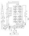
- FIG. 1 shows a circuit arrangement according to the invention.
- a switch V15 such as IGBT, GTO, IGCT
- the crowbar is completely inactive.
- the full rotor current flows into an inverter and is regulated by this. If a mains short circuit occurs on the medium voltage, an asynchronous generator supplies a short-circuit compensation short-circuit due to the full excitation.
- the current is limited only by the stray inductances of the asynchronous generator and medium-voltage transformer, the maximum current reaching the following value: I stator ⁇ 1.8 • U network Xtr + X ⁇ 1 + X ⁇ 2 ⁇ '
- X tr is the total leakage impedance of the transformer
- X1 is the leakage impedance of the stator
- X2 ' is the leakage impedance of the rotor.
- the maximum stator current in the case of a short circuit at the medium voltage is in practice of the order of magnitude of up to 8 times the rated stator current.
- the rotor current is transformer coupled to the stator current and also reaches up to 8 times the nominal rotor current. This high compensation current can not be technically meaningfully guided or absorbed by the inverter.
- a rotor inverter is shut down due to the overcurrent.
- the rotor current continues to flow through freewheeling diodes of the rotor inverter and charges a DC link C3.
- the voltage rises across a capacitor C10 in the crowbar.
- the switch V15 Upon reaching a voltage limit across the capacitor C10, the switch V15 is turned on.
- a resistor R15 takes over the entire rectified rotor current, and the voltage across the capacitor C10 drops below the voltage limit, so that the switch V15 is turned off.
- the voltage then rises again via the capacitor C10, due to the rotor current, and the switch V15 is switched on again.
- the rate of change of current and thus also the clock frequency are determined by L15.
- the clock frequency is up to the kHz range and can not be done by natural commutation of thyristors, since the rotor frequency is a maximum of 15 Hz.
- the switch V15 If the compensation current falls below the rated rotor current, the switch V15 is completely switched off and the rotor current commutates back into the converter.
- the inverter starts its operation and regulation and actively feeds into the short circuit. While the adjustable resistor is active, the mains inverter can be switched off, but it is also the simultaneous operation possible.
- a thyristor V10 is provided in the Crow-Bar, which automatically measures the voltage and, in the event of a failure, is ignited by the switch V15 or in the case of a direct generator short circuit. L10 prevents a too fast current increase, so as not to destroy the thyristor V10. In doing so, D10 prevents a fast discharge from a capacitor C10 through the switch V15.
- the control of the switch V15 can either be done directly in the crowbar or by the control card of the inverter.
- a possible short circuit is in Fig. 2 shown, wherein the dashed line represents the medium voltage and the solid line represents the mains voltage.
- the short circuit occurs at the moment 0 msec. on.
- the current jumps immediately to the maximum value and then stops, due to the compensation process from.
- the high current is absorbed by the crow-bar or resistor.
- the current is again taken over and regulated by the inverter.
- the generator is over-excited and supplies capacitive reactive power to the grid during the mains short-circuit. But it can also be fed inductive current in the short circuit.
- the default can be chosen freely. Due to the voltage drop across the medium-voltage transformer, the mains voltage is ⁇ 20% of the nominal voltage.
- the voltage does not rise abruptly to the nominal value but via a dU / dt edge. Due to the edge steepness of the recurring mains voltage and the time constant of the generator, a dynamic overcurrent occurs in the stator and rotor. This overcurrent must be able to be supplied by the inverter and will not cause the rotor inverter to trip. If the edge steepness is too great or if there is a phase error between the generator voltage and the recurrent mains voltage, then the dynamic overcurrent or equalizing current becomes too high, the rotor inverter is switched off.
- the controllable resistance also takes over the compensation current for a short time and after falling below the rated rotor current, the resistor is switched off and the rotor inverter takes over its control again. During the voltage dip and at recurring Voltage, the variable resistor is activated in a short time. The rotor inverter is switched off during this time.
- an additional impedance for example, a resistor or a choke
- a resistor or a choke can be inserted into the stator circuit.
- a contactor K20 is inserted between the medium-voltage transformer and the generator-inverter system. Over the contactor K20 there is a resistor R20 in parallel. If the short circuit occurs, the contactor K20 is opened and the stator current flows through the resistor R20.
- FIG. 4 the voltage-time curve with additional resistance.
- the stator current is limited and sounds faster than just with the regulated crow bar.
- the contactor must switch very fast, so that the resistance is active for very short voltage drops. It can also be an anti-parallel thyristor with natural commutation are used, for example, a shutdown of 6.7 msec. at 50 Hz. This gives a fast switch, but has the disadvantage of high losses compared to the contactor solution.
- the switch In the FIG. 4 is the switch after 10 msec. open. After the compensation process, the inverter takes over the regulation again. Due to the additional voltage drop across the resistor, the residual supply voltage is higher than without additional impedance in the stator. With the recurring voltage, the additional resistor limits the dynamic stator current increase and allows higher voltage edges or lower overcurrents.
- the free-wheeling diodes of IGBT modules are not designed for very high pulse currents. Therefore, the components of the controlled resistance were placed in the crowbar.
- a circuit arrangement with powerful freewheeling diodes shows FIG. 5 , Switch V15 is directly coupled to the DC link of the inverter and directly controls the DC link voltage. This would simplify the entire construction. The additional standard Crow Bar is retained for extreme situations.
- the additional resistor must be designed for all extreme situations.
- the rotor inverters IGBTs are switched off and the rotor short-circuit current flows through the freewheeling diodes into the DC link.
- the additional resistor is activated and the short-circuit energy is absorbed in the additional resistor.
- the rotor inverter is reactivated and the additional resistor will be switched off. It is also possible to first switch off the auxiliary resistor and switch on the rotor inverter. It is also possible to operate the additional resistor and the rotor inverter simultaneously.
Description
Die Erfindung betrifft eine insbesondere zum Einsatz bei einer Windenergieanlage mit variabler Drehzahl bestimmte Schaltungsanordnung umfassend einen doppeltgespeisten Asynchrongenerator, einen Zusatzwiderstand und einen Umrichter.The invention relates to a particular intended for use in a wind turbine with variable speed circuitry comprising a double-fed asynchronous generator, an additional resistor and a converter.
Solche zum Einsatz bei drehzahlvariablen Windenergieanlagen vorgesehene Schaltungsanordnungen werden in der Praxis vielfach eingesetzt und zählen daher durch offenkundige Vorbenutzung zum Stand der Technik. Im Betrieb erweist es sich jedoch beim Einsatz doppeltgespeister Asynchronmaschinen (DASM) als hinderlich, dass diese sich im Falle eines Netzkurzschlusses auf der Mittelspannungsebene vom Netz trennen. Daher kann die erwünschte Netzstabilisierung durch eine Windkraftanlage, die mit einer doppeltgespeisten Asynchronmaschine betrieben wird, nicht realisiert werden.Such provided for use in variable-speed wind turbines circuits are widely used in practice and therefore include by prior public use of the prior art. In operation, however, the use of double-fed asynchronous machines (DASM) proves to be an obstacle to their disconnection from the grid in the event of a grid short-circuit on the medium voltage level. Therefore, the desired network stabilization can not be realized by a wind turbine operated with a double-fed asynchronous machine.
In der Vergangenheit erfolgte die erforderliche Netzstabilisierung daher durch die Netzbetreiber mit konventionellen Kraftwerken. Aufgrund der schnell steigenden Anzahl der Windkraftanlagen und der damit verbundenen rasch ansteigenden Leistung, die inzwischen die Größe konventioneller Kraftwerke erreicht haben, müssen jedoch auch die Anforderungen der Windkraftanlagen an diejenigen der konventionellen Kraftwerke angepasst werden. Insbesondere wird zunehmend eine dauerhafte Netzkoppelung verlangt, damit die Windenergieanlage während und nach beendetem Mittelspannungsnetzkurzschluss das Netz wieder aufbauen und stabilisieren kann.In the past, network stabilization was therefore required by the grid operators with conventional power plants. Due to the rapidly increasing number of wind turbines and the associated rapidly increasing performance, which have now reached the size of conventional power plants, but also the requirements of wind turbines must be adapted to those of conventional power plants. In particular, a permanent grid connection is increasingly required so that the wind turbine can rebuild and stabilize the grid during and after completion of medium-voltage grid short circuit.
Der Erfindung liegt die Aufgabe zugrunde, eine Schaltungsanordnung zum Einsatz bei Windkraftanlagen mit einer Asynchronmaschine zu schaffen, mittels der die erhöhten Anforderngen an moderne Windkraftanlagen, insbesondere hinsichtlich der Netzstabilisierung, erfüllt werden können.The invention has for its object to provide a circuit arrangement for use in wind turbines with an asynchronous, by means of which the increased request levels of modern wind turbines, especially in terms of grid stabilization, can be met.
Diese Aufgabe wird erfindungsgemäß mit einer Schaltungsanordnung gemäß den Merkmalen des Patentanspruchs 1 gelöst. Die Unteransprüche betreffen besonders zweckmäßige Weiterbildungen der Erfindung.This object is achieved with a circuit arrangement according to the features of claim 1. The subclaims relate to particularly expedient developments of the invention.
Erfindungsgemäß ist also eine Schaltungsanordnung vorgesehen, bei welcher der Zusatzwiderstand mittels eines schnellen Schalters derart regelbar ist, dass der Umrichter im Netzkurzschlussfall zumindest teilweise vorübergehend abschaltbar ist, um den Rotorstrom mittels des Zusatzwiderstandes kurzzeitig zu übernehmen, und nach Abklingen des Rotorkurzschlussstromes zur aktiven Einkopplung eines Kurzschlussstromes ins Netz wieder zuschaltbar ist.According to the invention, therefore, a circuit arrangement is provided in which the additional resistance can be regulated by means of a fast switch such that the converter is at least partially temporarily switched off in the event of a short circuit, in order to temporarily take over the rotor current by means of the additional resistor, and after decay of the rotor short-circuit current for active coupling of a short-circuit current back into the network is switchable.
Mit der erfindungsgemäßen Schaltungsanordnung wird im Netzkurzschlussfall kapazitiver Strom oder induktiver Strom in den Kurzschluss geliefert, weil dadurch je nach Anforderung der Netzbetreiber das Netz optimal stabilisiert werden kann. Üblicherweise wird ein kapazitiver Strom erwünscht, um die induktiven Netzverbraucher zu versorgen.With the circuit arrangement according to the invention, capacitive current or inductive current is supplied in the short circuit in the event of a network short circuit, because the network can be optimally stabilized depending on the requirements of the network operator. Typically, a capacitive current is desired to power the inductive power consumers.
Wenn bei wiederkehrender Netzspannung der Rotorwechselrichter abgeschaltet und ein Überstrom dann durch den regelbaren Widerstand übernommen wird, um nach Abklingen des Überstromes und Abschalten des geregelten Widerstandes den Rotorstrom aktiv zu übernehmen, wird eine mögliche Abschaltng bzw, Netztrennung der Windenergieanlage bei insbesondere plötzlich wiederkehrender Netzspannung vermieden.If the rotor inverter is switched off and an overcurrent is then taken over by the controllable resistor in order to actively take over the rotor current after the overcurrent has ceased and the regulated resistor has been switched off, a possible shutdown or network separation of the wind energy plant is avoided, in particular with suddenly recurring mains voltage.
Hierdurch können die erhöhten Netzanforderungen im Betrieb der mit einem Asynchrongenerator ausgestatteten Windkraftanlage zur Netzstabilisierung optimal erfüllt werden, weil dabei im Falle eines Netzkurzschlusses auf der Mittelspannungsebene keine Trennung vom Netz eintritt. Hierzu ist im Rotorkreis beispielsweise ein als regelbarer Lastwiderstand ausgeführter Zusatzwiderstand oder ein Crow-Bar, der hierzu mit dem Zusatzwiderstand ausgestattet ist, eingefügt worden, der beim Eintreten des Netzkurzschlussfalls die Rotorkurzschlussenergie aufnimmt und anschließend, nach Abklingen des Kurzschlussstromes, abgeschaltet wird. Der Lastwiderstand wird mit einem insbesondere aktiv abschaltbaren Schalter geregelt, der insbesondere kein natürlich kommutierter Thyristor ist. Der vorhandehe Rotorwechselrichter des Vier-Quadranten-Umrichters wird sofort nach Eintreten des Netzkurzschlusses kurzzeitig deaktiviert und nach Abklingen des Kurzschlussausgleichsvorganges, wobei der Schwellenwert vorteilhafter Weise unterhalb eines Rotorwechselrichternennstromes liegt, wieder aktiviert und speist dann währen des Netzkurzschlusses und bei wiederkehrender Netzspannung die erforderliche Leistung in das Netz.As a result, the increased network requirements during operation of the equipped with an asynchronous generator wind turbine for grid stabilization can be optimally met, because in the case of a network short circuit on the medium voltage level no separation from the network occurs. For this purpose, in the rotor circuit, for example, a run as a variable load resistor additional resistance or crow bar, which is equipped with the additional resistance, has been inserted, which absorbs the rotor short-circuit energy at the onset of Netzkurzschlussfalls and then, after the short-circuit current has disappeared, is switched off. The load resistance is controlled by a switch that can be switched off, in particular, which is in particular not a naturally commutated thyristor. The existing rotor inverter of the four-quadrant inverter is briefly deactivated immediately after the onset of the network short circuit and after the short circuit compensation process, the threshold is advantageously below a rotor inverter rated current again activated and then feeds the required power during the network short circuit and recurrent mains voltage Network.
Als besonders vorteilhaft erweist sich dabei eine Abwandlung der vorliegenden Erfindung, bei welcher die Schaltungsanordnung mehrere abhängig oder unabhängig voneinander schaltbare Widerstände aufweist. Hierdurch wird erreicht, dass der hohe Rotorkurzschlussstrom, der häufig 1000 A übersteigt, auf mehrere Schalter aufgeteilt werden kann, da diese abschaltbaren Schalter für den Gesamtstrom sehr aufwendig parallel geschaltet werden müssen.In this case, a modification of the present invention in which the circuit arrangement has a number of dependent or independently switchable resistors proves particularly advantageous. This ensures that the high rotor short-circuit current, which often exceeds 1000 A, can be divided among several switches, as these switchable switch for the total current very expensive to be connected in parallel.
Besonders vorteilhaft ist auch eine Schaltungsanordnung mit einem Zweipunktregler, zur Regelung des Zusatzwiderstandes, weil dadurch eine sehr einfache, schnelle und robuste Regelung aufgebaut werden kann.Also particularly advantageous is a circuit arrangement with a two-point controller, for controlling the additional resistance, because a very simple, fast and robust control can be constructed thereby.
Hierbei erweist sich eine weitere Abwandlung als besonders zweckmäßig, wenn die Regelung des aktiven Schalters mit einer Pulsweitenmodulation mit einer festen Taktfrequenz erfolgt, weil auf diese Weise eine digitale Regelung mit einer festen Taktfrequenz erfolgen kann.In this case, a further modification proves to be particularly useful if the control of the active switch with a pulse width modulation with a fixed clock frequency, because in this way a digital control can be done with a fixed clock frequency.
Weiterhin ist es auch besonders Erfolg versprechend, wenn die Regelung des aktiven Schalters mit einem P-Regler, PI-Regler oder PID-Regler erfolgt. Hierdurch wird erreicht, dass beim Eintreten des Netzkurzschlusses der Rotorkurzschlussstrom bzw. die Rotorklemmspannung optimal geregelt werden können.Furthermore, it is also particularly promising, if the control of the active switch with a P-controller, PI controller or PID controller takes place. This ensures that the rotor short-circuit current or the rotor clamping voltage can be optimally controlled when the mains short circuit occurs.
Außerdem ist nach einer weiteren besonders vorteilhaften Ausgestaltung im Statorkreis kurzzeitig eine Zusatzimpedanz eingefügt, um den Stator und Rotorstrom zu begrenzen. Durch das bedarfsweise Einfügen der Zusatzimpedanz kann der Stator- und Rotorstrom bei wiederkehrender Netzspannung begrenzt werden.In addition, according to a further particularly advantageous embodiment, an additional impedance is temporarily inserted in the stator circuit in order to limit the stator and rotor current. By inserting the additional impedance as needed, the stator and rotor current can be limited at recurring mains voltage.
Besonders zweckmäßig ist auch eine Ausführungsform, bei der im Statorkreis parallel zur Zusatzimpedanz ein schnelles Schütz eingesetzt ist, um so die Zusatzimpedanz im normalen Betrieb zu überbrücken und keine Verluste zu erzeugen.Particularly useful is also an embodiment in which in the stator circuit parallel to the additional impedance, a fast contactor is used so as to bridge the additional impedance in normal operation and to generate no losses.
Ferner ist es auch besonders Erfolg versprechend, wenn im Statorkreis parallel zum Widerstand zumindest ein Thyristor mit natürlicher Kommutierung eingesetzt ist. Hierdurch wird erreicht, dass, verglichen mit aktiv abschaltbaren Schaltern, reduzierte Verluste im Normalbetrieb entstehen und die Kosten geringer sind.Furthermore, it is also particularly promising if at least one thyristor with natural commutation is used in the stator circuit parallel to the resistor. This ensures that, compared with active turn-off switches, reduced losses occur in normal operation and the costs are lower.
Weiterhin kann die Schaltungsanordnung in besonders vorteilhafter Weise so ausgeführt sein, dass am Zwischenkreis des Umrichters ein geregelter Widerstand betrieben wird, weil dadurch einige Bauteile in der Crow-Bar gespart werden können und die Regelung des Rotorwechselrichters dauerhaft den Rotorphasenstrom misst.Furthermore, the circuit arrangement can be carried out in a particularly advantageous manner so that a regulated resistance is operated at the intermediate circuit of the inverter, because thereby some components in the crowbar can be saved and the control of the rotor inverter permanently measures the rotor phase current.
Eine andere besonders zweckmäßige Ausgestaltung der Erfindung wird auch dann erreicht, wenn sowohl in der Crow-Bar als auch am Zwischenkreis des Umrichters ein geregelter Widerstand betrieben wird. Hierdurch wird erreicht, dass eine Leistungsaufteilung erfolgt und kleinere Einzelschalter eingesetzt werden können. Gegen Ende des Ausgleichsvorganges des Rotorkurzschlussstromes erfolgt die Übernahme des gesamten Rotorstromes, und die Regelung des Rotorwechselrichters misst dann den gesamten Phasenstrom.Another particularly advantageous embodiment of the invention is also achieved when a regulated resistance is operated both in the crowbar and on the DC link of the inverter. This ensures that a power distribution takes place and smaller individual switches can be used. Towards the end of the compensation process of the rotor short-circuit current takes over the acquisition of the entire rotor current, and the control of the rotor inverter then measures the entire phase current.
Die Erfindung lässt verschiedene Ausführungsformen zu. Zur weiteren Verdeutlichung ihres Grundprinzips ist eine davon in der Zeichnung dargestellt und wird nachfolgend beschrieben. Diese zeigt in
- Fig.1
- eine erfindungsgemäße Schaltungsanordnung;
- Fig.2
- einen möglichen Kurzschlussverlauf;
- Fig.3
- Schaltungsanordnung mit regelbarem Rotorwiderstand und Zusatzstatorwiderstand;
- Fig.4
- einen Spannungs- und Strom-Zeitverlauf mit Zusatzwiderstand;
- Fig.5
- Schaltungsanordnung mit verstärkten Inverterdioden und regelbarem Lastwiderstand im Zwischenkreis.
- Fig.1
- a circuit arrangement according to the invention;
- Fig.2
- a possible short circuit course;
- Figure 3
- Circuit arrangement with controllable rotor resistance and additional stator resistance;
- Figure 4
- a voltage and current time course with additional resistance;
- Figure 5
- Circuit arrangement with amplified inverter diodes and controllable load resistance in the DC link.

Dabei ist Xtr die gesamte Streuimpedanz des Transformators, X1 die Streuimpedanz des Stators und X2' die Streuimpedanz des Rotors. Der maximale Statorstrom liegt bei einem Kurzschluss an der Mittelspannung in der Praxis in der Größenordnung von bis zu dem 8-fachen Statornennstrom. Der Rotorstrom ist transformatorisch mit dem Statorstrom gekoppelt und erreicht auch bis zu dem 8-fachen des Rotornennstromes. Dieser hohe Ausgleichstrom kann nicht technisch sinnvoll vom Umrichter geführt bzw. aufgenommen werden. Beim Eintritt des Kurzschlusses wird ein Rotorwechselrichter bedingt durch den Überstrom abgeschaltet. Der Rotorstrom fließt weiter über Freilaufdioden des Rotorwechselrichters und lädt einen Zwischenkreis C3 auf. Gleichzeitig steigt die Spannung über einen Kondensator C10 in der Crow-Bar. Beim Erreichen eines Spannungsgrenzwertes über den Kondensator C10 wird der Schalter V15 eingeschaltet. Ein Widerstand R15 übernimmt den gesamten gleichgerichteten Rotorstrom, und die Spannung über den Kondensator C10 sinkt unter den Spannungsgrenzwert, so dass der Schalter V15 abgeschaltet wird. Die Spannung steigt anschließend über den Kondensator C10, bedingt durch den Rotorstrom, wieder an und der Schalter V15 wird wieder eingeschaltet. Die Stromänderungsgeschwindigkeit und damit auch die Taktfrequenz werden durch L15 bestimmt. Die Taktfrequenz liegt bis in den kHz-Bereich und kann nicht durch natürliche Kommutierung von Thyristoren erfolgen, da die Rotorfrequenz bei maximal 15 Hz liegt. Mit dieser Zweipunkt-Regelung wird eine konstante Gegenspannung für die Rotorspannung erzeugt und der Ausgleichstrom klingt bedingt durch die konstant hohe Gegenspannung in kürzester Zeit ab. Der gesamte Strom ist vom Rotorwechselrichter in die Crow-Bar kommutiert. Der Umrichterstrom ist nahe null. Der Crow-Bar Strom wird von der Steuerkarte gemessen und ausgewertet. Der Lastwiderstand ist für den maximalen Strom ausgelegt und die Einschaltdauer des Schalters V15 ist anfangs nahe 100 %. Mit sinkendem Ausgleichstrom wird die Einschaltdauer geringer und liegt beim Rotornennstrom bei ca. 12 %, was in etwa 1/8 des maximalen Stromes entspricht. Denkbar wären auch mehrere Widerstände, die einzeln zu und abgeschaltet werden können. Unterschreitet der Ausgleichstrom den Rotornennstrom, so wird der Schalter V15 ganz abgeschaltet und der Rotorstrom kommutiert in den Umrichter zurück. Der Umrichter nimmt seinen Betrieb und die Regelung auf und speist aktiv in den Kurzschluss. Während der regelbare Widerstand aktiv ist, kann der Netzwechselrichter abgeschaltet werden, es ist aber auch der gleichzeitige Betrieb möglich. In der Crow-Bar ist aus Sicherheitsgründen ein Thyristor V10 vorgesehen, der selbständig die Spannung misst und bei Versagen von dem Schalter V15 oder beim direkten Generatorkurzschluss gezündet wird. L10 verhindert einen zu schnellen Stromanstieg, um den Thyristor V10 nicht zu zerstören. Dabei verhindert D10 eine Schnellentladung von einem Kondensator C10 durch den Schalter V15. Die Regelung des Schalters V15 kann entweder direkt in der Crow-Bar oder durch die Steuerkarte des Umrichters erfolgen.Where X tr is the total leakage impedance of the transformer, X1 is the leakage impedance of the stator and X2 'is the leakage impedance of the rotor. The maximum stator current in the case of a short circuit at the medium voltage is in practice of the order of magnitude of up to 8 times the rated stator current. The rotor current is transformer coupled to the stator current and also reaches up to 8 times the nominal rotor current. This high compensation current can not be technically meaningfully guided or absorbed by the inverter. When the short circuit occurs, a rotor inverter is shut down due to the overcurrent. The rotor current continues to flow through freewheeling diodes of the rotor inverter and charges a DC link C3. At the same time, the voltage rises across a capacitor C10 in the crowbar. Upon reaching a voltage limit across the capacitor C10, the switch V15 is turned on. A resistor R15 takes over the entire rectified rotor current, and the voltage across the capacitor C10 drops below the voltage limit, so that the switch V15 is turned off. The voltage then rises again via the capacitor C10, due to the rotor current, and the switch V15 is switched on again. The rate of change of current and thus also the clock frequency are determined by L15. The clock frequency is up to the kHz range and can not be done by natural commutation of thyristors, since the rotor frequency is a maximum of 15 Hz. With this two-point control, a constant counter voltage for the rotor voltage is generated and the compensation current sounds due to the constant high counter voltage in no time. The entire current is commutated by the rotor inverter into the crowbar. The inverter current is close to zero. The Crow-Bar current is measured and evaluated by the control card. The load resistance is for the maximum Current designed and the duty cycle of the switch V15 is initially close to 100%. With decreasing compensation current, the duty cycle is lower and is at the rotor rated current at about 12%, which corresponds to about 1/8 of the maximum current. Also conceivable would be several resistors that can be turned on and off individually. If the compensation current falls below the rated rotor current, the switch V15 is completely switched off and the rotor current commutates back into the converter. The inverter starts its operation and regulation and actively feeds into the short circuit. While the adjustable resistor is active, the mains inverter can be switched off, but it is also the simultaneous operation possible. For safety reasons, a thyristor V10 is provided in the Crow-Bar, which automatically measures the voltage and, in the event of a failure, is ignited by the switch V15 or in the case of a direct generator short circuit. L10 prevents a too fast current increase, so as not to destroy the thyristor V10. In doing so, D10 prevents a fast discharge from a capacitor C10 through the switch V15. The control of the switch V15 can either be done directly in the crowbar or by the control card of the inverter.
Ein möglicher Kurzschlussverlauf ist in
Bei extrem schnellen Spannungsanstiegszeiten kann in den Statorkreis eine Zusatzimpedanz, beispielsweise durch einen Widerstand oder eine Drossel, eingefügt werden. Ein solches System ist in der
In der
Die Freilaufdioden von IGBT-Modulen sind nicht für sehr hohe Pulsströme ausgelegt. Daher wurden die Bauteile des geregelten Widerstandes in die Crow-Bar gelegt. Eine Schaltungsanordnung mit leistungsstarken Freilaufdioden zeigt
Denkbar ist auch der völlige Verzicht der Crow-Bar. In diesem Fall muss der Zusatzwiderstand für alle Extremsituationen ausgelegt werden. Im Kurzschlussfall werden die Rotorwechselrichter IGBTs abgeschaltet und der Rotorkurzschlussstrom fließt durch die Freilaufdioden in den Zwischenkreis. Beim Überschreiten eines Grenzwertes wird der Zusatzwiderstand aktiviert und die Kurzschlussenergie im Zusatzwiderstand aufgenommen. Nach Abklingen des Kurzschlussstromes wird der Rotorwechselrichter wieder aktiviert und der Zusatzwiderstand wird abgeschaltet. Es kann auch zuerst der Zusatzwiderstand abgeschaltet und der Rotorwechselrichter zugeschaltet werden. Es ist auch ein gleichzeitiger Betrieb des Zusatzwiderstandes und des Rotorwechselrichters möglich.Also possible is the complete renunciation of the Crow-Bar. In this case, the additional resistor must be designed for all extreme situations. In the event of a short circuit, the rotor inverters IGBTs are switched off and the rotor short-circuit current flows through the freewheeling diodes into the DC link. When a limit value is exceeded, the additional resistor is activated and the short-circuit energy is absorbed in the additional resistor. After the short-circuit current has subsided, the rotor inverter is reactivated and the additional resistor will be switched off. It is also possible to first switch off the auxiliary resistor and switch on the rotor inverter. It is also possible to operate the additional resistor and the rotor inverter simultaneously.
Claims (17)
- Variable speed wind energy plant having a switching arrangement comprising a double feed asynchronous generator, an additional resistance and a frequency converter with a rotor switching rectifier, whereby the switching arrangement includes a switch (V15) and means to control the operation of the additional resistance (R15), so that the rotor switching rectifier can be temporarily disconnected in the event of a network short-circuit and the rotor current can be provided briefly by the additional resistance,
characterised in that, after the rotor short-circuit current has attenuated, the rotor switching rectifier can be switched again to actively couple a short-circuit current into the network, that the switching arrangement is arranged in such a way that in the event of a network short-circuit, a capacitive current or an inductive current can be fed to the short-circuit from the wind energy plant, and that the rotor switching rectifier can also be disconnected when the network voltage returns in order to absorb excess current through the additional resistance (R15) and the additional resistance (R15) can be disconnected after the excess current has attenuated and the rotor current can be picked up by the rotor switching rectifier. - Wind energy plant according to Claim 1, characterised in that the frequency converter can be switched on once the attenuation of the rotor short-circuit current falls below a nominal rotor switching current level.
- Wind energy plant according to Claims 1 or 2, characterised in that the switching arrangement comprises a number of resistances (R15), which can be switched dependently or independently of each other.
- Wind energy plant according to at least one of the preceding claims, characterised by a two-position controller to control the additional resistance (R15).
- Wind energy plant according to at least one of the preceding claims, characterised in that the control of the switch (V15) is effected by means of pulse width modulation with a fixed pulse rate.
- Wind energy plant according to at least one of the preceding claims, characterised in that the additional resistance (R15) is in the form of a component of a crow-bar.
- Wind energy plant according to Claim 6, characterised in that the switch (V15) is a forced operation switch and that the means of controlling the operation of the crow-bar are so designed to operate the switch (V15).
- Wind energy plant according to Claim 6 or 7, characterised in that the crow-bar switch (V15) is controlled directly by the frequency converter card.
- Wind energy plant according to at least one of the preceding claims, characterised in that an additional impedance (R20) is temporarily inserted into the stator circuit in order to limit the stator and the rotor current.
- Wind energy plant according to at least one of the preceding claims, characterised in that a fast-action protection (K20) is inserted into the stator circuit in parallel to the resistance (R20).
- Wind energy plant according to at least one of the preceding claims, characterised in that at least one thyristor with natural commutation is inserted into the stator circuit in parallel to the resistance (R20).
- Wind energy plant according to at least one of the preceding claims, characterised in that an additional resistance (R15) is arranged in the intermediary circuit of the frequency converter.
- Wind energy plant according to at least one of the above Claims 6 to 10, characterised in that an additional resistance (R15) is arranged in both the crowbar and the frequency converter.
- Process for the operation of a variable speed wind energy plant comprising a switching arrangement with a double-feed asynchronous generator, an additional resistance (R15) and a frequency converter with a rotor switching rectifier, whereby the switching arrangement encompasses a switch (V15) and means to regulate the operation of the additional resistance (R15), so that the frequency converter is temporarily disconnected in the event of a network short-circuit and the rotor current supply is briefly taken over by the additional resistance (R15), characterised in that after the rotor short-circuit current has attenuated the rotor switching rectifier is switched to actively couple a short-circuit current into the network, that in the event of a network short-circuit a capacitive or an inductive current is fed to the short-circuit by the switching arrangement and that the rotor switching rectifier is disconnected when the network voltage is reinstated in order to absorb any excess current by the additional resistance (R15) and that the resistance (R15) is disconnected after the attenuation of this excess current and the rotor current feed is taken over by the rotor switching rectifier.
- Process according to Claim 14, characterised in that the additional resistance (R15) is regulated by a switch (V15).
- Process according to Claim 15, characterised in that the switch (V15) is controlled by a two-position controller.
- Process according to any one of the Claims 14 to 16, characterised in that the switch (V15) is regulated by pulse width modulation with a fixed pulse frequency.
Applications Claiming Priority (3)
| Application Number | Priority Date | Filing Date | Title |
|---|---|---|---|
| DE10203468 | 2002-01-29 | ||
| DE10206828A DE10206828A1 (en) | 2002-01-29 | 2002-02-18 | Circuit arrangement for use in a wind turbine |
| EP03704240A EP1470633A1 (en) | 2002-01-29 | 2003-01-23 | Circuit to be used in a wind power plant |
Related Parent Applications (4)
| Application Number | Title | Priority Date | Filing Date |
|---|---|---|---|
| WOPCT/DE03/00172 Previously-Filed-Application | 2003-01-23 | ||
| EP03704240.5 Division | 2003-01-23 | ||
| PCT/DE2003/000172 Previously-Filed-Application WO2003065567A1 (en) | 2002-01-29 | 2003-01-23 | Circuit to be used in a wind power plant |
| EP03704240A Division EP1470633A1 (en) | 2002-01-29 | 2003-01-23 | Circuit to be used in a wind power plant |
Publications (3)
| Publication Number | Publication Date |
|---|---|
| EP2244372A2 EP2244372A2 (en) | 2010-10-27 |
| EP2244372A3 EP2244372A3 (en) | 2012-04-25 |
| EP2244372B1 true EP2244372B1 (en) | 2015-03-04 |
Family
ID=27588133
Family Applications (1)
| Application Number | Title | Priority Date | Filing Date |
|---|---|---|---|
| EP09012812.5A Expired - Lifetime EP2244372B1 (en) | 2002-01-29 | 2003-01-23 | Switching device for a wind power plant |
Country Status (3)
| Country | Link |
|---|---|
| EP (1) | EP2244372B1 (en) |
| DE (1) | DE10206828A1 (en) |
| ES (1) | ES2533471T3 (en) |
Families Citing this family (14)
| Publication number | Priority date | Publication date | Assignee | Title |
|---|---|---|---|---|
| ES2310685T3 (en) * | 2002-09-24 | 2009-01-16 | Ids Holding Ag | GENERATOR SYSTEM WITH A GENERATOR COUPLED DIRECTLY TO THE NETWORK AND PROCEDURE TO CONTROL NETWORK FAILURES. |
| PT1499009E (en) * | 2003-07-15 | 2008-01-14 | Gamesa Innovation & Tech Sl | Control and protection of a doubly-fed induction generator system |
| AT504808B1 (en) | 2003-11-14 | 2009-08-15 | Bernecker & Rainer Ind Elektro | SYNCHRONOUS MACHINE |
| ES2245608B1 (en) | 2004-06-30 | 2007-03-01 | Gamesa Eolica S.A. | PROCEDURE AND DEVICE TO AVOID THE DISCONNECTION OF A NETWORK ELECTRICAL POWER GENERATION PARK. |
| DE102004033680B4 (en) * | 2004-07-09 | 2009-03-12 | Wobben, Aloys, Dipl.-Ing. | load resistance |
| US7859125B2 (en) | 2004-12-28 | 2010-12-28 | Vestas Wind Systems A/S | Method of controlling a wind turbine connected to an electric utility grid |
| DE102005046962A1 (en) * | 2005-09-30 | 2007-04-12 | Siemens Ag | Control system and method for controlling a permanently excited electric motor |
| DE102007017870B4 (en) | 2007-04-13 | 2022-03-31 | Senvion Gmbh | Method for operating a wind turbine in the event of overvoltages in the network |
| ES2337749B1 (en) * | 2007-07-18 | 2011-05-06 | Zigor Corporacion,S.A. | SYSTEM TO GUARANTEE THE CONTINUITY OF OPERATION OF AEROGENERATORS BEFORE TENSION HOLES. |
| JP4801779B2 (en) | 2007-12-14 | 2011-10-26 | 三菱重工業株式会社 | Wind power generator |
| DE102008026621A1 (en) * | 2008-02-15 | 2009-08-20 | Converteam Technology Ltd., Rugby | Single or multi-phase electrical circuit for switching current produced via alternating current or three-phase power controller, has controller with valves designed as disconnectable valves, where device is connected parallel to valves |
| CH701746A2 (en) * | 2009-09-03 | 2011-03-15 | Ids Holding Ag | Generator system with direct netzgekoppeltem generator and method for driving through grid disturbances. |
| CH701753A1 (en) * | 2009-09-03 | 2011-03-15 | Ids Holding Ag | Speed variable generator system for use in e.g. hydro power plant, has voltage limiter attached at secondary side of generator such that secondary sided current is derived during high current through frequency converter |
| DK2639449T3 (en) * | 2012-03-15 | 2016-03-21 | Siemens Ag | Electrical yaw drive for a wind turbine, the wind turbine and method for operating a wind turbine |
Family Cites Families (3)
| Publication number | Priority date | Publication date | Assignee | Title |
|---|---|---|---|---|
| JP3100805B2 (en) * | 1993-08-24 | 2000-10-23 | 東京電力株式会社 | Overvoltage protection device for variable speed pumped storage power generation system |
| JP3348944B2 (en) * | 1993-12-27 | 2002-11-20 | 株式会社東芝 | Control device for winding induction machine |
| JP2001268992A (en) * | 2000-03-17 | 2001-09-28 | Toshiba Corp | Variable speed controller |
-
2002
- 2002-02-18 DE DE10206828A patent/DE10206828A1/en not_active Withdrawn
-
2003
- 2003-01-23 EP EP09012812.5A patent/EP2244372B1/en not_active Expired - Lifetime
- 2003-01-23 ES ES09012812.5T patent/ES2533471T3/en not_active Expired - Lifetime
Also Published As
| Publication number | Publication date |
|---|---|
| EP2244372A3 (en) | 2012-04-25 |
| EP2244372A2 (en) | 2010-10-27 |
| DE10206828A1 (en) | 2003-08-14 |
| ES2533471T3 (en) | 2015-04-10 |
Similar Documents
| Publication | Publication Date | Title |
|---|---|---|
| EP1470633A1 (en) | Circuit to be used in a wind power plant | |
| EP1557925B1 (en) | Power converter apparatus and related driving method for generators with dynamically varying output power | |
| DE10114075B4 (en) | Power converter circuitry for dynamically variable power output generators | |
| DE60317183T2 (en) | Control and protection device for a double-fed induction generator system | |
| EP1921738B1 (en) | Method and device to control a dc-ac converter, particularly for a wind energy plant | |
| EP2244372B1 (en) | Switching device for a wind power plant | |
| WO2008116769A2 (en) | Method and device for operating an asynchronous motor with double feeds under transient grid voltage changes | |
| DE19735742B4 (en) | Over- and under-synchronous power converter cascade | |
| DE102011000459B4 (en) | Method for supplying reactive current with a converter and converter arrangement and energy supply system | |
| EP2200169B1 (en) | Method for starting a doubly-fed induction machine | |
| CH701746A2 (en) | Generator system with direct netzgekoppeltem generator and method for driving through grid disturbances. | |
| EP1561275B1 (en) | Generator system having a generator that is directly coupled to the mains, and method for controlling mains interruptions | |
| WO2009012776A2 (en) | Double-fed asynchronous generator and method for its operation | |
| EP2117108B1 (en) | Method for starting a system for generating electrical energy | |
| WO2012019834A2 (en) | Converter system and method for operating such a converter system | |
| DE102018105683A1 (en) | Method for operating an electronic circuit breaker of an inverter | |
| WO2009030692A1 (en) | Method and control unit for the short circuit current reduction in a double-fed asynchronous machine | |
| WO2020160841A1 (en) | Drive system with inverter and electric motor and method for operating a drive system | |
| EP3758214A1 (en) | Motor starter and method for starting an electric motor | |
| WO2003028203A1 (en) | Cascade with electronic disconnection and an enlarged rotational speed range | |
| EP1011189B1 (en) | Method and circuit for adjusting the intermediate link voltage to the supply voltage | |
| DE102011051732B3 (en) | Wind turbine | |
| EP2479859A1 (en) | Safety circuit | |
| DE102008064079A1 (en) | Electrical circuit producing method for producing electrical energy in e.g. gas turbine-power plant, involves interconnecting two poles of intermediate circuit by adjustable resistor when intermediate circuit voltage increases | |
| DE2237233C3 (en) | Circuit arrangement for a induction machine |
Legal Events
| Date | Code | Title | Description |
|---|---|---|---|
| PUAI | Public reference made under article 153(3) epc to a published international application that has entered the european phase |
Free format text: ORIGINAL CODE: 0009012 |
|
| AC | Divisional application: reference to earlier application |
Ref document number: 1470633 Country of ref document: EP Kind code of ref document: P |
|
| AK | Designated contracting states |
Kind code of ref document: A2 Designated state(s): AT BE BG CH CY CZ DE DK EE ES FI FR GB GR HU IE IT LI LU MC NL PT SE SI SK TR |
|
| PUAL | Search report despatched |
Free format text: ORIGINAL CODE: 0009013 |
|
| AK | Designated contracting states |
Kind code of ref document: A3 Designated state(s): AT BE BG CH CY CZ DE DK EE ES FI FR GB GR HU IE IT LI LU MC NL PT SE SI SK TR |
|
| RIC1 | Information provided on ipc code assigned before grant |
Ipc: H02P 9/10 20060101AFI20120316BHEP |
|
| RAP1 | Party data changed (applicant data changed or rights of an application transferred) |
Owner name: VESTAS WIND SYSTEMS A/S |
|
| 17P | Request for examination filed |
Effective date: 20121018 |
|
| 17Q | First examination report despatched |
Effective date: 20121210 |
|
| GRAP | Despatch of communication of intention to grant a patent |
Free format text: ORIGINAL CODE: EPIDOSNIGR1 |
|
| INTG | Intention to grant announced |
Effective date: 20141031 |
|
| GRAS | Grant fee paid |
Free format text: ORIGINAL CODE: EPIDOSNIGR3 |
|
| GRAA | (expected) grant |
Free format text: ORIGINAL CODE: 0009210 |
|
| AC | Divisional application: reference to earlier application |
Ref document number: 1470633 Country of ref document: EP Kind code of ref document: P |
|
| AK | Designated contracting states |
Kind code of ref document: B1 Designated state(s): AT BE BG CH CY CZ DE DK EE ES FI FR GB GR HU IE IT LI LU MC NL PT SE SI SK TR |
|
| REG | Reference to a national code |
Ref country code: GB Ref legal event code: FG4D Free format text: NOT ENGLISH |
|
| REG | Reference to a national code |
Ref country code: CH Ref legal event code: EP |
|
| REG | Reference to a national code |
Ref country code: IE Ref legal event code: FG4D Free format text: LANGUAGE OF EP DOCUMENT: GERMAN |
|
| REG | Reference to a national code |
Ref country code: ES Ref legal event code: FG2A Ref document number: 2533471 Country of ref document: ES Kind code of ref document: T3 Effective date: 20150410 |
|
| REG | Reference to a national code |
Ref country code: AT Ref legal event code: REF Ref document number: 714631 Country of ref document: AT Kind code of ref document: T Effective date: 20150415 |
|
| REG | Reference to a national code |
Ref country code: DE Ref legal event code: R096 Ref document number: 50315221 Country of ref document: DE Effective date: 20150416 |
|
| REG | Reference to a national code |
Ref country code: CH Ref legal event code: PCOW Free format text: NEW ADDRESS: HEDEAGER 42, 8200 AARHUS N (DK) |
|
| RAP2 | Party data changed (patent owner data changed or rights of a patent transferred) |
Owner name: VESTAS WIND SYSTEMS A/S |
|
| REG | Reference to a national code |
Ref country code: NL Ref legal event code: VDEP Effective date: 20150304 |
|
| PG25 | Lapsed in a contracting state [announced via postgrant information from national office to epo] |
Ref country code: FI Free format text: LAPSE BECAUSE OF FAILURE TO SUBMIT A TRANSLATION OF THE DESCRIPTION OR TO PAY THE FEE WITHIN THE PRESCRIBED TIME-LIMIT Effective date: 20150304 Ref country code: SE Free format text: LAPSE BECAUSE OF FAILURE TO SUBMIT A TRANSLATION OF THE DESCRIPTION OR TO PAY THE FEE WITHIN THE PRESCRIBED TIME-LIMIT Effective date: 20150304 |
|
| PG25 | Lapsed in a contracting state [announced via postgrant information from national office to epo] |
Ref country code: GR Free format text: LAPSE BECAUSE OF FAILURE TO SUBMIT A TRANSLATION OF THE DESCRIPTION OR TO PAY THE FEE WITHIN THE PRESCRIBED TIME-LIMIT Effective date: 20150605 |
|
| PG25 | Lapsed in a contracting state [announced via postgrant information from national office to epo] |
Ref country code: NL Free format text: LAPSE BECAUSE OF FAILURE TO SUBMIT A TRANSLATION OF THE DESCRIPTION OR TO PAY THE FEE WITHIN THE PRESCRIBED TIME-LIMIT Effective date: 20150304 |
|
| PG25 | Lapsed in a contracting state [announced via postgrant information from national office to epo] |
Ref country code: CZ Free format text: LAPSE BECAUSE OF FAILURE TO SUBMIT A TRANSLATION OF THE DESCRIPTION OR TO PAY THE FEE WITHIN THE PRESCRIBED TIME-LIMIT Effective date: 20150304 Ref country code: PT Free format text: LAPSE BECAUSE OF FAILURE TO SUBMIT A TRANSLATION OF THE DESCRIPTION OR TO PAY THE FEE WITHIN THE PRESCRIBED TIME-LIMIT Effective date: 20150706 Ref country code: SK Free format text: LAPSE BECAUSE OF FAILURE TO SUBMIT A TRANSLATION OF THE DESCRIPTION OR TO PAY THE FEE WITHIN THE PRESCRIBED TIME-LIMIT Effective date: 20150304 Ref country code: EE Free format text: LAPSE BECAUSE OF FAILURE TO SUBMIT A TRANSLATION OF THE DESCRIPTION OR TO PAY THE FEE WITHIN THE PRESCRIBED TIME-LIMIT Effective date: 20150304 |
|
| REG | Reference to a national code |
Ref country code: DE Ref legal event code: R097 Ref document number: 50315221 Country of ref document: DE |
|
| PG25 | Lapsed in a contracting state [announced via postgrant information from national office to epo] |
Ref country code: IT Free format text: LAPSE BECAUSE OF FAILURE TO SUBMIT A TRANSLATION OF THE DESCRIPTION OR TO PAY THE FEE WITHIN THE PRESCRIBED TIME-LIMIT Effective date: 20150304 |
|
| PLBE | No opposition filed within time limit |
Free format text: ORIGINAL CODE: 0009261 |
|
| STAA | Information on the status of an ep patent application or granted ep patent |
Free format text: STATUS: NO OPPOSITION FILED WITHIN TIME LIMIT |
|
| PG25 | Lapsed in a contracting state [announced via postgrant information from national office to epo] |
Ref country code: DK Free format text: LAPSE BECAUSE OF FAILURE TO SUBMIT A TRANSLATION OF THE DESCRIPTION OR TO PAY THE FEE WITHIN THE PRESCRIBED TIME-LIMIT Effective date: 20150304 |
|
| REG | Reference to a national code |
Ref country code: FR Ref legal event code: PLFP Year of fee payment: 14 |
|
| 26N | No opposition filed |
Effective date: 20151207 |
|
| PG25 | Lapsed in a contracting state [announced via postgrant information from national office to epo] |
Ref country code: SI Free format text: LAPSE BECAUSE OF FAILURE TO SUBMIT A TRANSLATION OF THE DESCRIPTION OR TO PAY THE FEE WITHIN THE PRESCRIBED TIME-LIMIT Effective date: 20150304 |
|
| PG25 | Lapsed in a contracting state [announced via postgrant information from national office to epo] |
Ref country code: BE Free format text: LAPSE BECAUSE OF NON-PAYMENT OF DUE FEES Effective date: 20160131 |
|
| PG25 | Lapsed in a contracting state [announced via postgrant information from national office to epo] |
Ref country code: LU Free format text: LAPSE BECAUSE OF FAILURE TO SUBMIT A TRANSLATION OF THE DESCRIPTION OR TO PAY THE FEE WITHIN THE PRESCRIBED TIME-LIMIT Effective date: 20160123 |
|
| REG | Reference to a national code |
Ref country code: CH Ref legal event code: PL |
|
| PG25 | Lapsed in a contracting state [announced via postgrant information from national office to epo] |
Ref country code: MC Free format text: LAPSE BECAUSE OF FAILURE TO SUBMIT A TRANSLATION OF THE DESCRIPTION OR TO PAY THE FEE WITHIN THE PRESCRIBED TIME-LIMIT Effective date: 20150304 |
|
| PG25 | Lapsed in a contracting state [announced via postgrant information from national office to epo] |
Ref country code: LI Free format text: LAPSE BECAUSE OF NON-PAYMENT OF DUE FEES Effective date: 20160131 Ref country code: CH Free format text: LAPSE BECAUSE OF NON-PAYMENT OF DUE FEES Effective date: 20160131 |
|
| REG | Reference to a national code |
Ref country code: IE Ref legal event code: MM4A |
|
| REG | Reference to a national code |
Ref country code: FR Ref legal event code: PLFP Year of fee payment: 15 |
|
| PG25 | Lapsed in a contracting state [announced via postgrant information from national office to epo] |
Ref country code: IE Free format text: LAPSE BECAUSE OF NON-PAYMENT OF DUE FEES Effective date: 20160123 |
|
| REG | Reference to a national code |
Ref country code: AT Ref legal event code: MM01 Ref document number: 714631 Country of ref document: AT Kind code of ref document: T Effective date: 20160123 |
|
| PG25 | Lapsed in a contracting state [announced via postgrant information from national office to epo] |
Ref country code: AT Free format text: LAPSE BECAUSE OF NON-PAYMENT OF DUE FEES Effective date: 20160123 |
|
| REG | Reference to a national code |
Ref country code: FR Ref legal event code: PLFP Year of fee payment: 16 |
|
| PG25 | Lapsed in a contracting state [announced via postgrant information from national office to epo] |
Ref country code: HU Free format text: LAPSE BECAUSE OF FAILURE TO SUBMIT A TRANSLATION OF THE DESCRIPTION OR TO PAY THE FEE WITHIN THE PRESCRIBED TIME-LIMIT; INVALID AB INITIO Effective date: 20030123 Ref country code: CY Free format text: LAPSE BECAUSE OF FAILURE TO SUBMIT A TRANSLATION OF THE DESCRIPTION OR TO PAY THE FEE WITHIN THE PRESCRIBED TIME-LIMIT Effective date: 20150304 |
|
| PG25 | Lapsed in a contracting state [announced via postgrant information from national office to epo] |
Ref country code: TR Free format text: LAPSE BECAUSE OF FAILURE TO SUBMIT A TRANSLATION OF THE DESCRIPTION OR TO PAY THE FEE WITHIN THE PRESCRIBED TIME-LIMIT Effective date: 20150304 |
|
| PG25 | Lapsed in a contracting state [announced via postgrant information from national office to epo] |
Ref country code: BG Free format text: LAPSE BECAUSE OF FAILURE TO SUBMIT A TRANSLATION OF THE DESCRIPTION OR TO PAY THE FEE WITHIN THE PRESCRIBED TIME-LIMIT Effective date: 20150304 |
|
| PGFP | Annual fee paid to national office [announced via postgrant information from national office to epo] |
Ref country code: GB Payment date: 20220118 Year of fee payment: 20 Ref country code: DE Payment date: 20220329 Year of fee payment: 20 |
|
| PGFP | Annual fee paid to national office [announced via postgrant information from national office to epo] |
Ref country code: FR Payment date: 20220126 Year of fee payment: 20 Ref country code: ES Payment date: 20220211 Year of fee payment: 20 |
|
| REG | Reference to a national code |
Ref country code: DE Ref legal event code: R071 Ref document number: 50315221 Country of ref document: DE |
|
| REG | Reference to a national code |
Ref country code: GB Ref legal event code: PE20 Expiry date: 20230122 |
|
| REG | Reference to a national code |
Ref country code: ES Ref legal event code: FD2A Effective date: 20230509 |
|
| PG25 | Lapsed in a contracting state [announced via postgrant information from national office to epo] |
Ref country code: GB Free format text: LAPSE BECAUSE OF EXPIRATION OF PROTECTION Effective date: 20230122 |
|
| P01 | Opt-out of the competence of the unified patent court (upc) registered |
Effective date: 20230521 |
|
| PG25 | Lapsed in a contracting state [announced via postgrant information from national office to epo] |
Ref country code: ES Free format text: LAPSE BECAUSE OF EXPIRATION OF PROTECTION Effective date: 20230124 |