EP2244324A1 - Cambered flow-field plate - Google Patents
Cambered flow-field plate Download PDFInfo
- Publication number
- EP2244324A1 EP2244324A1 EP09169517A EP09169517A EP2244324A1 EP 2244324 A1 EP2244324 A1 EP 2244324A1 EP 09169517 A EP09169517 A EP 09169517A EP 09169517 A EP09169517 A EP 09169517A EP 2244324 A1 EP2244324 A1 EP 2244324A1
- Authority
- EP
- European Patent Office
- Prior art keywords
- flow
- cell
- fuel
- field plate
- field
- Prior art date
- Legal status (The legal status is an assumption and is not a legal conclusion. Google has not performed a legal analysis and makes no representation as to the accuracy of the status listed.)
- Granted
Links
- 239000000446 fuel Substances 0.000 claims abstract description 86
- 239000007800 oxidant agent Substances 0.000 claims description 16
- 230000001590 oxidative effect Effects 0.000 claims description 16
- 230000001747 exhibiting effect Effects 0.000 claims description 5
- 239000012528 membrane Substances 0.000 description 31
- 239000007789 gas Substances 0.000 description 22
- 238000009792 diffusion process Methods 0.000 description 18
- QVGXLLKOCUKJST-UHFFFAOYSA-N atomic oxygen Chemical compound [O] QVGXLLKOCUKJST-UHFFFAOYSA-N 0.000 description 8
- 239000001301 oxygen Substances 0.000 description 8
- 229910052760 oxygen Inorganic materials 0.000 description 8
- 239000001257 hydrogen Substances 0.000 description 7
- 229910052739 hydrogen Inorganic materials 0.000 description 7
- 239000000463 material Substances 0.000 description 7
- OKKJLVBELUTLKV-UHFFFAOYSA-N Methanol Chemical compound OC OKKJLVBELUTLKV-UHFFFAOYSA-N 0.000 description 6
- PXHVJJICTQNCMI-UHFFFAOYSA-N Nickel Chemical compound [Ni] PXHVJJICTQNCMI-UHFFFAOYSA-N 0.000 description 6
- 229910000831 Steel Inorganic materials 0.000 description 6
- 239000010959 steel Substances 0.000 description 6
- UFHFLCQGNIYNRP-UHFFFAOYSA-N Hydrogen Chemical compound [H][H] UFHFLCQGNIYNRP-UHFFFAOYSA-N 0.000 description 5
- 230000008878 coupling Effects 0.000 description 5
- 238000010168 coupling process Methods 0.000 description 5
- 238000005859 coupling reaction Methods 0.000 description 5
- 238000007789 sealing Methods 0.000 description 5
- 239000003054 catalyst Substances 0.000 description 4
- 230000000875 corresponding effect Effects 0.000 description 4
- XLYOFNOQVPJJNP-UHFFFAOYSA-N water Substances O XLYOFNOQVPJJNP-UHFFFAOYSA-N 0.000 description 4
- OKTJSMMVPCPJKN-UHFFFAOYSA-N Carbon Chemical compound [C] OKTJSMMVPCPJKN-UHFFFAOYSA-N 0.000 description 3
- 238000006243 chemical reaction Methods 0.000 description 3
- 229910002804 graphite Inorganic materials 0.000 description 3
- 239000010439 graphite Substances 0.000 description 3
- 150000002500 ions Chemical class 0.000 description 3
- 229910052759 nickel Inorganic materials 0.000 description 3
- 239000011248 coating agent Substances 0.000 description 2
- 238000000576 coating method Methods 0.000 description 2
- -1 hydrogen ions Chemical class 0.000 description 2
- 230000002787 reinforcement Effects 0.000 description 2
- RYGMFSIKBFXOCR-UHFFFAOYSA-N Copper Chemical compound [Cu] RYGMFSIKBFXOCR-UHFFFAOYSA-N 0.000 description 1
- 239000003570 air Substances 0.000 description 1
- 230000004888 barrier function Effects 0.000 description 1
- 238000005452 bending Methods 0.000 description 1
- 239000007795 chemical reaction product Substances 0.000 description 1
- 239000004020 conductor Substances 0.000 description 1
- 230000001276 controlling effect Effects 0.000 description 1
- 229910052802 copper Inorganic materials 0.000 description 1
- 239000010949 copper Substances 0.000 description 1
- 230000002596 correlated effect Effects 0.000 description 1
- 230000007547 defect Effects 0.000 description 1
- 230000000694 effects Effects 0.000 description 1
- 230000005611 electricity Effects 0.000 description 1
- 239000003792 electrolyte Substances 0.000 description 1
- 150000002431 hydrogen Chemical class 0.000 description 1
- 238000004519 manufacturing process Methods 0.000 description 1
- 239000005518 polymer electrolyte Substances 0.000 description 1
Images


Classifications
-
- H—ELECTRICITY
- H01—ELECTRIC ELEMENTS
- H01M—PROCESSES OR MEANS, e.g. BATTERIES, FOR THE DIRECT CONVERSION OF CHEMICAL ENERGY INTO ELECTRICAL ENERGY
- H01M8/00—Fuel cells; Manufacture thereof
- H01M8/02—Details
- H01M8/0202—Collectors; Separators, e.g. bipolar separators; Interconnectors
- H01M8/0258—Collectors; Separators, e.g. bipolar separators; Interconnectors characterised by the configuration of channels, e.g. by the flow field of the reactant or coolant
- H01M8/0263—Collectors; Separators, e.g. bipolar separators; Interconnectors characterised by the configuration of channels, e.g. by the flow field of the reactant or coolant having meandering or serpentine paths
-
- H—ELECTRICITY
- H01—ELECTRIC ELEMENTS
- H01M—PROCESSES OR MEANS, e.g. BATTERIES, FOR THE DIRECT CONVERSION OF CHEMICAL ENERGY INTO ELECTRICAL ENERGY
- H01M8/00—Fuel cells; Manufacture thereof
- H01M8/02—Details
- H01M8/0202—Collectors; Separators, e.g. bipolar separators; Interconnectors
- H01M8/0247—Collectors; Separators, e.g. bipolar separators; Interconnectors characterised by the form
-
- C—CHEMISTRY; METALLURGY
- C01—INORGANIC CHEMISTRY
- C01B—NON-METALLIC ELEMENTS; COMPOUNDS THEREOF; METALLOIDS OR COMPOUNDS THEREOF NOT COVERED BY SUBCLASS C01C
- C01B3/00—Hydrogen; Gaseous mixtures containing hydrogen; Separation of hydrogen from mixtures containing it; Purification of hydrogen
- C01B3/02—Production of hydrogen or of gaseous mixtures containing a substantial proportion of hydrogen
-
- C—CHEMISTRY; METALLURGY
- C25—ELECTROLYTIC OR ELECTROPHORETIC PROCESSES; APPARATUS THEREFOR
- C25B—ELECTROLYTIC OR ELECTROPHORETIC PROCESSES FOR THE PRODUCTION OF COMPOUNDS OR NON-METALS; APPARATUS THEREFOR
- C25B15/00—Operating or servicing cells
- C25B15/08—Supplying or removing reactants or electrolytes; Regeneration of electrolytes
-
- C—CHEMISTRY; METALLURGY
- C25—ELECTROLYTIC OR ELECTROPHORETIC PROCESSES; APPARATUS THEREFOR
- C25B—ELECTROLYTIC OR ELECTROPHORETIC PROCESSES FOR THE PRODUCTION OF COMPOUNDS OR NON-METALS; APPARATUS THEREFOR
- C25B9/00—Cells or assemblies of cells; Constructional parts of cells; Assemblies of constructional parts, e.g. electrode-diaphragm assemblies; Process-related cell features
- C25B9/60—Constructional parts of cells
- C25B9/65—Means for supplying current; Electrode connections; Electric inter-cell connections
-
- H—ELECTRICITY
- H01—ELECTRIC ELEMENTS
- H01M—PROCESSES OR MEANS, e.g. BATTERIES, FOR THE DIRECT CONVERSION OF CHEMICAL ENERGY INTO ELECTRICAL ENERGY
- H01M8/00—Fuel cells; Manufacture thereof
-
- H—ELECTRICITY
- H01—ELECTRIC ELEMENTS
- H01M—PROCESSES OR MEANS, e.g. BATTERIES, FOR THE DIRECT CONVERSION OF CHEMICAL ENERGY INTO ELECTRICAL ENERGY
- H01M8/00—Fuel cells; Manufacture thereof
- H01M8/02—Details
- H01M8/0202—Collectors; Separators, e.g. bipolar separators; Interconnectors
- H01M8/0258—Collectors; Separators, e.g. bipolar separators; Interconnectors characterised by the configuration of channels, e.g. by the flow field of the reactant or coolant
-
- H—ELECTRICITY
- H01—ELECTRIC ELEMENTS
- H01M—PROCESSES OR MEANS, e.g. BATTERIES, FOR THE DIRECT CONVERSION OF CHEMICAL ENERGY INTO ELECTRICAL ENERGY
- H01M8/00—Fuel cells; Manufacture thereof
- H01M8/02—Details
- H01M8/0271—Sealing or supporting means around electrodes, matrices or membranes
- H01M8/0273—Sealing or supporting means around electrodes, matrices or membranes with sealing or supporting means in the form of a frame
-
- H—ELECTRICITY
- H01—ELECTRIC ELEMENTS
- H01M—PROCESSES OR MEANS, e.g. BATTERIES, FOR THE DIRECT CONVERSION OF CHEMICAL ENERGY INTO ELECTRICAL ENERGY
- H01M8/00—Fuel cells; Manufacture thereof
- H01M8/02—Details
- H01M8/0271—Sealing or supporting means around electrodes, matrices or membranes
- H01M8/0276—Sealing means characterised by their form
-
- H—ELECTRICITY
- H01—ELECTRIC ELEMENTS
- H01M—PROCESSES OR MEANS, e.g. BATTERIES, FOR THE DIRECT CONVERSION OF CHEMICAL ENERGY INTO ELECTRICAL ENERGY
- H01M8/00—Fuel cells; Manufacture thereof
- H01M8/02—Details
- H01M8/0271—Sealing or supporting means around electrodes, matrices or membranes
- H01M8/028—Sealing means characterised by their material
- H01M8/0284—Organic resins; Organic polymers
-
- H—ELECTRICITY
- H01—ELECTRIC ELEMENTS
- H01M—PROCESSES OR MEANS, e.g. BATTERIES, FOR THE DIRECT CONVERSION OF CHEMICAL ENERGY INTO ELECTRICAL ENERGY
- H01M8/00—Fuel cells; Manufacture thereof
- H01M8/02—Details
- H01M8/0271—Sealing or supporting means around electrodes, matrices or membranes
- H01M8/0286—Processes for forming seals
-
- H—ELECTRICITY
- H01—ELECTRIC ELEMENTS
- H01M—PROCESSES OR MEANS, e.g. BATTERIES, FOR THE DIRECT CONVERSION OF CHEMICAL ENERGY INTO ELECTRICAL ENERGY
- H01M8/00—Fuel cells; Manufacture thereof
- H01M8/02—Details
- H01M8/0289—Means for holding the electrolyte
-
- H—ELECTRICITY
- H01—ELECTRIC ELEMENTS
- H01M—PROCESSES OR MEANS, e.g. BATTERIES, FOR THE DIRECT CONVERSION OF CHEMICAL ENERGY INTO ELECTRICAL ENERGY
- H01M8/00—Fuel cells; Manufacture thereof
- H01M8/02—Details
- H01M8/0297—Arrangements for joining electrodes, reservoir layers, heat exchange units or bipolar separators to each other
-
- H—ELECTRICITY
- H01—ELECTRIC ELEMENTS
- H01M—PROCESSES OR MEANS, e.g. BATTERIES, FOR THE DIRECT CONVERSION OF CHEMICAL ENERGY INTO ELECTRICAL ENERGY
- H01M8/00—Fuel cells; Manufacture thereof
- H01M8/10—Fuel cells with solid electrolytes
- H01M2008/1095—Fuel cells with polymeric electrolytes
-
- H—ELECTRICITY
- H01—ELECTRIC ELEMENTS
- H01M—PROCESSES OR MEANS, e.g. BATTERIES, FOR THE DIRECT CONVERSION OF CHEMICAL ENERGY INTO ELECTRICAL ENERGY
- H01M8/00—Fuel cells; Manufacture thereof
- H01M8/02—Details
- H01M8/0202—Collectors; Separators, e.g. bipolar separators; Interconnectors
- H01M8/0204—Non-porous and characterised by the material
- H01M8/0206—Metals or alloys
-
- H—ELECTRICITY
- H01—ELECTRIC ELEMENTS
- H01M—PROCESSES OR MEANS, e.g. BATTERIES, FOR THE DIRECT CONVERSION OF CHEMICAL ENERGY INTO ELECTRICAL ENERGY
- H01M8/00—Fuel cells; Manufacture thereof
- H01M8/02—Details
- H01M8/0202—Collectors; Separators, e.g. bipolar separators; Interconnectors
- H01M8/0204—Non-porous and characterised by the material
- H01M8/0213—Gas-impermeable carbon-containing materials
-
- H—ELECTRICITY
- H01—ELECTRIC ELEMENTS
- H01M—PROCESSES OR MEANS, e.g. BATTERIES, FOR THE DIRECT CONVERSION OF CHEMICAL ENERGY INTO ELECTRICAL ENERGY
- H01M8/00—Fuel cells; Manufacture thereof
- H01M8/02—Details
- H01M8/0202—Collectors; Separators, e.g. bipolar separators; Interconnectors
- H01M8/0204—Non-porous and characterised by the material
- H01M8/0223—Composites
- H01M8/0228—Composites in the form of layered or coated products
-
- H—ELECTRICITY
- H01—ELECTRIC ELEMENTS
- H01M—PROCESSES OR MEANS, e.g. BATTERIES, FOR THE DIRECT CONVERSION OF CHEMICAL ENERGY INTO ELECTRICAL ENERGY
- H01M8/00—Fuel cells; Manufacture thereof
- H01M8/10—Fuel cells with solid electrolytes
- H01M8/1009—Fuel cells with solid electrolytes with one of the reactants being liquid, solid or liquid-charged
- H01M8/1011—Direct alcohol fuel cells [DAFC], e.g. direct methanol fuel cells [DMFC]
-
- Y—GENERAL TAGGING OF NEW TECHNOLOGICAL DEVELOPMENTS; GENERAL TAGGING OF CROSS-SECTIONAL TECHNOLOGIES SPANNING OVER SEVERAL SECTIONS OF THE IPC; TECHNICAL SUBJECTS COVERED BY FORMER USPC CROSS-REFERENCE ART COLLECTIONS [XRACs] AND DIGESTS
- Y02—TECHNOLOGIES OR APPLICATIONS FOR MITIGATION OR ADAPTATION AGAINST CLIMATE CHANGE
- Y02E—REDUCTION OF GREENHOUSE GAS [GHG] EMISSIONS, RELATED TO ENERGY GENERATION, TRANSMISSION OR DISTRIBUTION
- Y02E60/00—Enabling technologies; Technologies with a potential or indirect contribution to GHG emissions mitigation
- Y02E60/30—Hydrogen technology
- Y02E60/50—Fuel cells
Definitions
- the invention relates to a flow-field plate, particularly for a fuel cell or a reformer cell.
- Fuel cells are devices for converting energy of a chemical reaction into electricity. When operating, a fuel and an oxidant are steadily supplied to the cell. Fuel and oxidant react in the presence of an electrolyte, such that the cell produces electrical current at its anode side and outputs a reaction product at its cathode.
- a single conventional fuel cell typically produces a low voltage, i.e. typically in the range from 0.5 Volts to 1.2 Volts, at a comparatively high current, wherein the current depends on the size of the reaction area, i.e. theoretically up to 3 Amperes per square centimetre (3A/cm 2 ) of active area in the cell. As the active area, i.e.
- the area of the membrane electrode assembly in a modern fuel cell may easily exceed an area of 100cm 2 , a single cell theoretically may output a current of up to 300 A at a low voltage of typically below 1.0 Volts.
- these high currents at a low voltage are difficult to handle, since the voltage of one fuel cell is to low for modern applications.
- a plurality of cells are connected in series, the voltages of the cells thus adding. Further to being electrically coupled the cells are connected in series with respect to the supply of fuel and an oxidant, the draining fuel line of one cell being the supply line of a next cell. Similarly the fuel cells may be connected in series with respect to the oxidant.
- Conventional fuel cells typically are of flat, planar shape and in many cases exhibit a rectangular shape.
- a serial connection of a plurality of fuel cells forms a stack, wherein the flat fuel cells are stacked one upon another thus forming a cuboid having the footprint of a single fuel cell and the height corresponding to the number of stacked fuel cells.
- Said stack of fuel cells thus forms an easy to handle plurality of fuel cells providing a high output current at a convenient voltage.
- the fuel cells of said stack conventionally are firmly connected in order to apply a mechanical pressure onto the fuel cells and in order to provide a sufficient mechanical strength to the components of fuel cells, i.e. the membrane and gas diffusion layers.
- the stacking of the cells is also conveniently used for applying a mechanical pressure onto the sidewalls of each fuel cell, which effectuates the flow-field plates of a fuel cell being pressed against a gas diffusion layer, thus lowering the ohmic contact resistance for dissipating the produced current. Accordingly said pressure is desired for enabling or at least improving the operation of the cells as described in more detail below.
- a reformer cell which can be considered as a reverse fuel cell, may have a very similar design as the described embodiments of fuel cells
- the invention as described below is not limited to a fuel cell, but can be applied to a flow-field plate of a reformer cell analogously.
- the invention relates to and is disclosed for a flow-field plate usable in a fuel cell or a reformer cell.
- FIG. 1 schematically depicts a cross sectional view of a fuel cell 100, wherein the depicted fuel cell may be of any arbitrary fuel cell type.
- the described embodiment relates to any fuel cell comprising a membrane electrode assembly, abbreviated as MEA, and at least one gas diffusion layer, abbreviated GDL, and a pair of flow-field plates surrounding these layers.
- the fuel cell may be a low temperature or high temperature fuel cell comprising a proton exchange membrane (PEM).
- PEM proton exchange membrane
- the fuel cell may be fuelled by hydrogen and oxygen or air, i.e. the oxygen from the air; or the fuel cell may be a so-called direct methanol fuel cell (DMFC), which is fuelled by methanol and oxygen, or the oxygen comprised in the air; or the fuel cell may be of any other type.
- DMFC direct methanol fuel cell
- the depicted fuel cell comprises a proton exchange membrane 110, which adjoins at both of its sides to gas diffusion layers (GDLs) 120a, 120b, which in turn adjoin to a first flow-field plate 130a and a second flow-field plate 130b at their outer faces.
- GDLs gas diffusion layers
- the proton exchange membrane is a semi permeable membrane allowing the ions to pass from the anode side through the membrane to the cathode, where the ions combine with the oxidant.
- PEMFC proton exchange membrane fuel cell
- the cell is fuelled with hydrogen and air, wherein hydrogen is supplied to the anode side and oxygen or air as oxidant is supplied to the cathode side.
- PEM in some literature abbreviates "polymer electrolyte membrane", wherein said membrane fulfils the purpose of the semi-permeable membrane.
- flow-field plates 130a, 130b serve as anode and cathode, i.e. for collecting the electrons produced by ionizing the fuel and conducting electrical current. Plates 130a and 130b accordingly may have electrical connectors for connecting the cell to an electric circuit.
- the anode and cathode may be implemented as a layer of conducting material applied on the faces of membrane 110, the anode and cathode having an electrical coupling to the outside of the cell.
- the fuel i.e. the hydrogen
- the resulting electrons are captured by the anode and the hydrogen ions, i.e. protons, travel through membrane 110 to the cathode side of the membrane, where they combine with the supplied oxidant, i.e. oxygen or oxygen as contained in air in the case of hydrogen as fuel, to produce water.
- Said reaction is accelerated by a catalyst, which in one embodiment may be applied as a coating to the membrane, said membrane comprising at least one layer of catalyst at the anode side, optionally another layer of catalyst on the cathode side of the membrane.
- membrane 110 is covered at both sides by gas diffusion layers (GDLs) 120a, 120b.
- GDLs gas diffusion layers
- the gas diffusion layers help to manage the produced water on the cathode side, since a fuel cell allows an appropriate amount of water to contact membrane 110 to keep that humidified.
- the GDLs promote the exit of water from the cathode to help eliminate flooding of the cell, which would stop any operation of the cell.
- the GDLs separate the membrane, where the fuel is split and the electrons are produced, from flow-field plates 130a, 130b, which serve as electrodes in the depicted embodiment, the GDLs must enable a transport of the electrons to electrodes.
- the gas diffusion layers accordingly must electrically couple the electrodes to the membrane, particularly to the catalyst on the membrane. To reduce the electrical resistance between anode and cathode, i.e. between the flow-field plates over GDLs and membrane, a contact pressure of the flow-field plates onto the GDLs is required.
- the gas diffusion layers must couple the membrane to the flow-field plates thermally for dissipating heat, which is produced when ionizing the fuel. Since a maximum temperature of a fuel cell must not be exceeded in order to prevent damaging of the fuel cell, and furthermore for controlling the temperature of the fuel cell to an optimum operating temperature, the gas diffusion layers also serve as a thermal coupling between membrane 110 and flow-field plates 130a, 130b. Similar as described above for the electrical coupling, the thermal coupling requires at least a minimum contact pressure of the flow-field plates 130a, 130b to the gas diffusion layers 120a, 120b and the membrane 110.
- a contact pressure between the flow-field plates and the gas diffusion layers furthermore is required in order to force the flow of gases through the flow field channels 140a, 140b.
- the fuel and the oxidant i.e. gasiform hydrogen and air or gasiform oxygen in this embodiment, are supplied to the fuel cell through openings - not shown in fig. 1 - in the flow-field plates. Both the fuel and the oxidant then either travel through the channels 140a, 140b of the flow field in the flow-field plates until it reaches the respective outlet opening at the end of the flow-field channels or they travel through the gas diffusion layer to the membrane where the fuel is ionized on the anode side and the oxidant combines with the ionized fuel ions on the cathode side.
- a flow of fuel or oxidant taking a shortcut from the inlet to the outlet without travelling through the channels but bypassing the barriers separating the channels is undesirable.
- At least one of the opposing flow-field plates exhibits a cambering in its relaxed state, the flow-field plate thus exhibiting a three dimensional curvature, which produces a contact pressure on the inner volume of the cell in its assembled state.
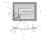
- Figures 2a, 2b depict an embodiment of flow-field plate 200, wherein fig. 2a depicts a front view of a flow-field plate and fig. 2b depicts a cross sectional view along cut line A - A'.
- Flow-field plate 200 may be considered as one embodiment of plate 130a, 130b as of fig. 1 , i.e. the plate may be suitable for the anode and the cathode side.
- the fuel cell in one embodiment may have a square or quadrangular shape as depicted.
- the fuel cell may have any arbitrary shape including any rounded or circular shape.
- Flow-field plate 200 as depicted in fig. 2a exhibits at least one inlet opening 210 for supplying fuel or oxidant and at least one channel for conducting fuel or oxidant.
- the openings 210 lead into channels 220, which conduct the fuel/oxidant to the at least one outlet opening 230.
- the plurality of meandering channels 220 i.e. the flow-field, optionally may be surrounded by a circumferential boundary area 240, which in the figure is depicted as the dashed area.
- Boundary area 240 in one embodiment may be used for connecting two flow-field plates or for applying the cell into an attachment, wherein the attachment touches the boundary area only.
- Fig. 2b depicts a cross sectional view along cut line A - A' through flow-field plate 200 exhibiting a cambering at least in x-direction.
- the flow-field plate in x-direction accordingly forms a curvature. Since the material of the flow-field plate is flexible and due to the pulling of the boundary area to an opposing plate, the flow-field plate will exhibit a contact pressure on its opposing plate as it is deformed on assembly of the fuel cell. In this way the cambering of the flow-field plate effectuates a desired contact pressure onto an opposing plate.
- the flow-field plate may also exhibit a cambering in the y-direction.
- boundary area 240 may not exhibit any cambering, but instead is plain flat, such that it does not effectuate a contact pressure.
- Said boundary area in one embodiment may be used to mechanically join opposing flow-field plates.
- cambering of the flow-field plate may not be uniform across the surface area of the plate. Instead the cambering may have any three-dimensional structure, wherein said three-dimensional structure may depend on the design of the flow-field, the material of the flow-field plate, the desired contact pressure and other factors. In one embodiment the cambering may be modelled and calculated using a finite-element modelling and calculation.
- the flow-field plate Due to the cambering the flow-field plate exhibits a curvature in the cambered area, i.e. except the circumferential boundary area 240. As illustrated the curvature is nonuniform across the cambered area.
- section 260 exhibits a cambering different from that of section 261, which in turn is different from the curvature of section 262.
- Said different cambering of areas of the flow-field plate in one embodiment may depend on the design of the flow-field. Due to the structuring of the gas flow channels in the flow-field, the channel sidewalls 221 a, 221 b effectuate a reinforcement of the flow-field plate in the direction of the channels, whereas they have a much smaller reinforcement effect when bending the plate perpendicular to the direction of the channel sidewalls. Consequently, since the cambering of the flow-field plate in sections 260 and 262 respectively is perpendicular to the direction of the gas flow channels, i.e.
- first curvature radius R1 as illustrated by arrows 270, 272.
- Curvature radius R1 differs from curvature radius R2 as illustrated by arrow 271, since the cambering of section 261 is parallel to the direction of the gas flow channels, i.e. parallel to the direction of the corresponding channel sidewalls.
- the curvature of the plate also depends on specifics of the material used, particularly on the rigidity of the material.
- the flow-field plate may be produced from steel, particularly from corrosive-resistant steel.
- the flow-field plate may exhibit a layered structure comprising at least two layers of material.
- the flow-field plate may comprise a layer of steel and a layer of nickel on the flow-field side of the plate.
- the steel layer essentially may provide the mechanical properties of the flow-field plate such as the mechanical stability, rigidity and the geometrical shape of the plate including the flow-field. Said steel layer is then nickelized during production, such that the steel layer receives a nickel coating at least on its flow-field side.
- the flow-field plate may comprise a layer for improving electrical conductivity of the plate, i.e. a layer of copper. Said layer may be applied to the outside of the plate and/or below the optional nickel layer at the flow-field side of the plate.
- the flow-field plate may be produced from graphite or may comprise a layer of graphite for incorporating graphite specific properties into the flow-field plate.
- Figures 3a and 3b schematically depict a fuel cell 300, wherein fig. 3a depicts the flow-field plates 310a and 310b in their relaxed position, i.e. before assembling the cell.
- Cell 300 may furthermore comprise a semi-permeable membrane 320 as well as first and second gas diffusion layers 330a, 330b as described above with reference to fig. 1 .
- Flow-field plates 310a and 310b exhibit a cambering effectuating a curvature in their relaxed state, wherein the curvature of the two opposing plates may be mirror-inverted as depicted in the figure.
- the invention may not be limited in this regard.
- only one of the two facing flow-field plates may be cambered as described above, whereas the residual plate is plain flat and advantageously stiff and non-deformable in order to resist a contact pressure caused by the cambering of the opposing flow field plate.
- Flow-field plates 310a, 310b exhibit a flow-field and corresponding channel sidewalls 311 a and 311 b respectively.
- a sealing means 340a, 340b may be applied before the cell is assembled, wherein said sealing means seals the inner volume of the cell against its surrounding once the cell is assembled.
- Said sealing means advantageously is of an electrically isolating material.
- each flow-field plate may optionally exhibit a flat circumferential boundary area 360a and 360b respectively.
- Said circumferential boundary area may be of particular use when assembling the cell, i.e. for clamping the cell parts together.
- both flow-field plates comprise a circumferential boundary area 360a, 360b respectively, wherein the width of the boundary area may be the same.
- the cambered areas 350a and 350b may have the same dimensions, whereas the circumferential area 360b of one of the flow-field plates, i.e. of flow-field plate 310b in fig. 3a , may have a significantly wider extension.
- Figure 3b depicts the fuel cell 300 in its assembled state, i.e. wherein flow-field plates 310a, 310b at their circumferential boundary areas are mechanically clamped.
- the flow-field plates essentially do not show a curvature any more but apply a contact pressure on gas diffusion layers 330a and 330b respectively.
- channel sidewalls 311 a and 311 b i.e. the front face of the channels sidewalls, are pressed on the gas diffusion layers thus preventing the flow of the gasiform fuel or oxidant to shortcut the way through the flow-field channels.
- said pressure also enables or improves the electrical and thermal connection of the flow-field plates 310a, 310b to membrane 320 in order enable a flow of electrical current and for dissipating thermal heat produced when operating the cell.
- the fuel or reformer cell comprises at least one flow-field plate exhibiting a cambering in its relaxed condition for producing a contact pressure when assembled in said cell.
- At least one electrical isolator 340a, b and/or 370 may separate the flow-field plates in the assembled state.
- fig. 3b shows one of a plurality of possible solutions for clamping the flow-field plates 310a and 310b together, wherein all solutions have in common, that the clamping force is applied to the circumferential boundary area of the flow-field plates.
- the boundary areas of the opposing flow-field plates are not identical, but the boundary area 360b of plate 310b is wider.
- said boundary area 360b is flanged or crimped, such that it encompasses the boundary area 360a of plate 310a at least partially, wherein the plates are isolated for example by isolator 370.
- the boundary areas 360a, 360b of the two opposing flow-field plates may have the same width.
- an additional clamp is used, wherein the clamp jaws attach to the boundary areas thus pulling these together.
- Said additional clamp may be either of electrically isolating material or an isolating layer may be applied to electrically isolate the flow-field plates from each other.
Abstract

Description
- The invention relates to a flow-field plate, particularly for a fuel cell or a reformer cell.
- Fuel cells are devices for converting energy of a chemical reaction into electricity. When operating, a fuel and an oxidant are steadily supplied to the cell. Fuel and oxidant react in the presence of an electrolyte, such that the cell produces electrical current at its anode side and outputs a reaction product at its cathode. A single conventional fuel cell typically produces a low voltage, i.e. typically in the range from 0.5 Volts to 1.2 Volts, at a comparatively high current, wherein the current depends on the size of the reaction area, i.e. theoretically up to 3 Amperes per square centimetre (3A/cm2) of active area in the cell. As the active area, i.e. the area of the membrane electrode assembly in a modern fuel cell, may easily exceed an area of 100cm2, a single cell theoretically may output a current of up to 300 A at a low voltage of typically below 1.0 Volts. Technically these high currents at a low voltage are difficult to handle, since the voltage of one fuel cell is to low for modern applications.
- For generating higher voltages in conventional fuel cell systems a plurality of cells are connected in series, the voltages of the cells thus adding. Further to being electrically coupled the cells are connected in series with respect to the supply of fuel and an oxidant, the draining fuel line of one cell being the supply line of a next cell. Similarly the fuel cells may be connected in series with respect to the oxidant.
- Conventional fuel cells typically are of flat, planar shape and in many cases exhibit a rectangular shape. Conventionally a serial connection of a plurality of fuel cells forms a stack, wherein the flat fuel cells are stacked one upon another thus forming a cuboid having the footprint of a single fuel cell and the height corresponding to the number of stacked fuel cells. Said stack of fuel cells thus forms an easy to handle plurality of fuel cells providing a high output current at a convenient voltage. The fuel cells of said stack conventionally are firmly connected in order to apply a mechanical pressure onto the fuel cells and in order to provide a sufficient mechanical strength to the components of fuel cells, i.e. the membrane and gas diffusion layers.
- In order to remove one of the fuel cells from the stack, for example in case of a defect, the corresponding electrical lines and supply lines have to be disconnected and the mechanical fixing of the stack must be unlocked. Accordingly removing of a single cell from the stack causes a comparatively high effort. Furthermore the number of fuel cells cannot be adapted as desired without considerable effort, since the electrical couplings and supply lines have to be adjusted to any change in the number of fuel cells. As a consequence stacks of fuel cells typically are available comprising a predefined and nearly unchangeable number of cells.
- In conventional stacks of fuel cells the stacking of the cells is also conveniently used for applying a mechanical pressure onto the sidewalls of each fuel cell, which effectuates the flow-field plates of a fuel cell being pressed against a gas diffusion layer, thus lowering the ohmic contact resistance for dissipating the produced current. Accordingly said pressure is desired for enabling or at least improving the operation of the cells as described in more detail below. However, it is a trade-off between providing a high mechanical pressure on a fuel cell for allowing a good ohmic contact and destroying a cell by said pressure.
- Consequently an alternative solution for applying a contact pressure from the flow-field plates on the gas diffusion layers is desired.
- In the following the invention is disclosed with respect to the accompanying figures, wherein
- Fig. 1
- depicts a schematic cross sectional view through a fuel cell;
- Figs. 2a, 2b
- depicts a schematic front view and a cross sectional view of a flow-field plate;
- Figs.3a, 3b
- depict a fuel cell before and after assembly.
- The following description particularly relates to fuel cells. However, since a reformer cell, which can be considered as a reverse fuel cell, may have a very similar design as the described embodiments of fuel cells, the invention as described below is not limited to a fuel cell, but can be applied to a flow-field plate of a reformer cell analogously. Hence, the invention relates to and is disclosed for a flow-field plate usable in a fuel cell or a reformer cell.
-
Figure 1 schematically depicts a cross sectional view of afuel cell 100, wherein the depicted fuel cell may be of any arbitrary fuel cell type. In order to elucidate the technical background of the invention, the described embodiment relates to any fuel cell comprising a membrane electrode assembly, abbreviated as MEA, and at least one gas diffusion layer, abbreviated GDL, and a pair of flow-field plates surrounding these layers. Generally the fuel cell may be a low temperature or high temperature fuel cell comprising a proton exchange membrane (PEM). The fuel cell may be fuelled by hydrogen and oxygen or air, i.e. the oxygen from the air; or the fuel cell may be a so-called direct methanol fuel cell (DMFC), which is fuelled by methanol and oxygen, or the oxygen comprised in the air; or the fuel cell may be of any other type. - The depicted fuel cell comprises a
proton exchange membrane 110, which adjoins at both of its sides to gas diffusion layers (GDLs) 120a, 120b, which in turn adjoin to a first flow-field plate 130a and a second flow-field plate 130b at their outer faces. - The proton exchange membrane is a semi permeable membrane allowing the ions to pass from the anode side through the membrane to the cathode, where the ions combine with the oxidant. In operation, for example when considering a so-called proton exchange membrane fuel cell (PEMFC), the cell is fuelled with hydrogen and air, wherein hydrogen is supplied to the anode side and oxygen or air as oxidant is supplied to the cathode side. Note that PEM in some literature abbreviates "polymer electrolyte membrane", wherein said membrane fulfils the purpose of the semi-permeable membrane.
- In the depicted embodiment flow-
field plates Plates membrane 110, the anode and cathode having an electrical coupling to the outside of the cell. - When the fuel, i.e. the hydrogen, is ionized at the anode side of membrane, the resulting electrons are captured by the anode and the hydrogen ions, i.e. protons, travel through
membrane 110 to the cathode side of the membrane, where they combine with the supplied oxidant, i.e. oxygen or oxygen as contained in air in the case of hydrogen as fuel, to produce water. Said reaction is accelerated by a catalyst, which in one embodiment may be applied as a coating to the membrane, said membrane comprising at least one layer of catalyst at the anode side, optionally another layer of catalyst on the cathode side of the membrane. - As illustrated,
membrane 110 is covered at both sides by gas diffusion layers (GDLs) 120a, 120b. The gas diffusion layers help to manage the produced water on the cathode side, since a fuel cell allows an appropriate amount of water to contactmembrane 110 to keep that humidified. In addition, the GDLs promote the exit of water from the cathode to help eliminate flooding of the cell, which would stop any operation of the cell. Since the GDLs separate the membrane, where the fuel is split and the electrons are produced, from flow-field plates - Furthermore, the gas diffusion layers must couple the membrane to the flow-field plates thermally for dissipating heat, which is produced when ionizing the fuel. Since a maximum temperature of a fuel cell must not be exceeded in order to prevent damaging of the fuel cell, and furthermore for controlling the temperature of the fuel cell to an optimum operating temperature, the gas diffusion layers also serve as a thermal coupling between
membrane 110 and flow-field plates field plates gas diffusion layers membrane 110. - A contact pressure between the flow-field plates and the gas diffusion layers furthermore is required in order to force the flow of gases through the
flow field channels fig. 1 - in the flow-field plates. Both the fuel and the oxidant then either travel through thechannels - Hence, there is a need for the flow-field plates to apply a contact pressure onto the gas diffusion layers, or more generally speaking, on the inner volume of the cell.
- For applying a contact pressure at least one of the opposing flow-field plates exhibits a cambering in its relaxed state, the flow-field plate thus exhibiting a three dimensional curvature, which produces a contact pressure on the inner volume of the cell in its assembled state.
-
Figures 2a, 2b depict an embodiment of flow-field plate 200, whereinfig. 2a depicts a front view of a flow-field plate andfig. 2b depicts a cross sectional view along cut line A - A'. Flow-field plate 200 may be considered as one embodiment ofplate fig. 1 , i.e. the plate may be suitable for the anode and the cathode side. - Note that the fuel cell in one embodiment may have a square or quadrangular shape as depicted. However, the fuel cell may have any arbitrary shape including any rounded or circular shape.
- Flow-
field plate 200 as depicted infig. 2a exhibits at least oneinlet opening 210 for supplying fuel or oxidant and at least one channel for conducting fuel or oxidant. Theopenings 210 lead intochannels 220, which conduct the fuel/oxidant to the at least oneoutlet opening 230. - The plurality of meandering
channels 220, i.e. the flow-field, optionally may be surrounded by acircumferential boundary area 240, which in the figure is depicted as the dashed area.Boundary area 240 in one embodiment may be used for connecting two flow-field plates or for applying the cell into an attachment, wherein the attachment touches the boundary area only. On saidboundary area 240 at least one circumferential sealing means 250 may be applied. -
Fig. 2b depicts a cross sectional view along cut line A - A' through flow-field plate 200 exhibiting a cambering at least in x-direction. The flow-field plate in x-direction accordingly forms a curvature. Since the material of the flow-field plate is flexible and due to the pulling of the boundary area to an opposing plate, the flow-field plate will exhibit a contact pressure on its opposing plate as it is deformed on assembly of the fuel cell. In this way the cambering of the flow-field plate effectuates a desired contact pressure onto an opposing plate. - Note that the flow-field plate may also exhibit a cambering in the y-direction.
- In one embodiment the
boundary area 240 may not exhibit any cambering, but instead is plain flat, such that it does not effectuate a contact pressure. Said boundary area in one embodiment may be used to mechanically join opposing flow-field plates. - Note that the cambering of the flow-field plate may not be uniform across the surface area of the plate. Instead the cambering may have any three-dimensional structure, wherein said three-dimensional structure may depend on the design of the flow-field, the material of the flow-field plate, the desired contact pressure and other factors. In one embodiment the cambering may be modelled and calculated using a finite-element modelling and calculation.
- Due to the cambering the flow-field plate exhibits a curvature in the cambered area, i.e. except the
circumferential boundary area 240. As illustrated the curvature is nonuniform across the cambered area. In the depictedembodiment section 260 exhibits a cambering different from that ofsection 261, which in turn is different from the curvature of section 262. - Said different cambering of areas of the flow-field plate in one embodiment may depend on the design of the flow-field. Due to the structuring of the gas flow channels in the flow-field, the channel sidewalls 221 a, 221 b effectuate a reinforcement of the flow-field plate in the direction of the channels, whereas they have a much smaller reinforcement effect when bending the plate perpendicular to the direction of the channel sidewalls. Consequently, since the cambering of the flow-field plate in
sections 260 and 262 respectively is perpendicular to the direction of the gas flow channels, i.e. perpendicular to the correlated sidewalls 221 a and 221 b respectively, the cambering results in first curvature radius R1 as illustrated byarrows section 261 is parallel to the direction of the gas flow channels, i.e. parallel to the direction of the corresponding channel sidewalls. - The curvature of the plate also depends on specifics of the material used, particularly on the rigidity of the material. In one embodiment the flow-field plate may be produced from steel, particularly from corrosive-resistant steel. In alternative embodiments the flow-field plate may exhibit a layered structure comprising at least two layers of material. In one alternative embodiment, the flow-field plate may comprise a layer of steel and a layer of nickel on the flow-field side of the plate. The steel layer essentially may provide the mechanical properties of the flow-field plate such as the mechanical stability, rigidity and the geometrical shape of the plate including the flow-field. Said steel layer is then nickelized during production, such that the steel layer receives a nickel coating at least on its flow-field side. In a second alternative embodiment the flow-field plate may comprise a layer for improving electrical conductivity of the plate, i.e. a layer of copper. Said layer may be applied to the outside of the plate and/or below the optional nickel layer at the flow-field side of the plate. In still another alternative the flow-field plate may be produced from graphite or may comprise a layer of graphite for incorporating graphite specific properties into the flow-field plate.
-
Figures 3a and 3b schematically depict afuel cell 300, whereinfig. 3a depicts the flow-field plates Cell 300 may furthermore comprise asemi-permeable membrane 320 as well as first and secondgas diffusion layers fig. 1 . - Flow-
field plates - Flow-
field plates corresponding channel sidewalls - Besides a cambered area 350 each flow-field plate may optionally exhibit a flat
circumferential boundary area circumferential boundary area cambered areas circumferential area 360b of one of the flow-field plates, i.e. of flow-field plate 310b infig. 3a , may have a significantly wider extension. -
Figure 3b depicts thefuel cell 300 in its assembled state, i.e. wherein flow-field plates - In this state the flow-field plates essentially do not show a curvature any more but apply a contact pressure on
gas diffusion layers particular channel sidewalls field plates membrane 320 in order enable a flow of electrical current and for dissipating thermal heat produced when operating the cell. - Hence, the fuel or reformer cell comprises at least one flow-field plate exhibiting a cambering in its relaxed condition for producing a contact pressure when assembled in said cell.
- In order to prevent an electrical shortcut between the flow-field plates, which in this depicted embodiment also serve as electrodes, and for sealing the inner volume of the cell against a surrounding atmosphere at least one
electrical isolator 340a, b and/or 370 may separate the flow-field plates in the assembled state. - Note that
fig. 3b shows one of a plurality of possible solutions for clamping the flow-field plates boundary area 360b ofplate 310b is wider. For mechanically clamping the flow-field plates, saidboundary area 360b is flanged or crimped, such that it encompasses theboundary area 360a ofplate 310a at least partially, wherein the plates are isolated for example byisolator 370. - In an alternative embodiment, which is not shown in the figures, the
boundary areas - In this way the cambering of the flow-field plates applies a contact pressure on the gas diffusion layer, wherein the amount of applied pressure may be adjusted by the amount of cambering. Accordingly there is no need for applying said contact pressure from outside of the cell. A single fuel cell is thus ready for operation without being mounted in a stack of fuel cells for applying said pressure.
Claims (8)
- Fuel or reformer cell (300) comprising at least one flow-field plate (310a) exhibiting a cambering in its relaxed condition for producing a contact pressure when assembled in said cell (300).
- Fuel or reformer cell (300) of claim 1 wherein the flow-field plate (310a) exhibits a non-cambered circumferential boundary area (360a).
- Fuel or reformer cell (300) of any preceding claim wherein the flow-field plate (310a) exhibits inlet and outlet openings (210, 230) for supplying and draining off fuel or oxidant.
- Fuel or reformer cell (300) of any preceding claim, wherein the flow-field plate (310a) serves as either cathode or anode.
- Fuel or reformer cell (300) of any preceding claim, further comprising a second flow-field plate (310b) exhibiting a cambering in its relaxed condition for producing a contact pressure when assembled in said cell (300).
- Fuel or reformer cell (300) of claim 5, wherein the flow-field plates (310a, 310b) are clamped together at their circumferential boundary areas (360a, 360b).
- Fuel or reformer cell of claim 5, wherein both flow-field plates (310a, 310b) exhibit a circumferential boundary area (360a, 360b), wherein the circumferential boundary areas are of different width.
- Fuel or reformer cell (300) of claim 7, wherein the boundary area (360b) of one of the flow-field plates is crimped or spun over to encompass the boundary area (360a) of the residual flow-field plate (310a).
Applications Claiming Priority (1)
| Application Number | Priority Date | Filing Date | Title |
|---|---|---|---|
| DE102009017779A DE102009017779A1 (en) | 2009-04-20 | 2009-04-20 | Modular fuel cell system |
Publications (2)
| Publication Number | Publication Date |
|---|---|
| EP2244324A1 true EP2244324A1 (en) | 2010-10-27 |
| EP2244324B1 EP2244324B1 (en) | 2013-11-27 |
Family
ID=42262398
Family Applications (3)
| Application Number | Title | Priority Date | Filing Date |
|---|---|---|---|
| EP09169525A Withdrawn EP2244325A3 (en) | 2009-04-20 | 2009-09-04 | Fuel cell comprising a crimped flow-field plate |
| EP09169517.1A Active EP2244324B1 (en) | 2009-04-20 | 2009-09-04 | Cambered Flow-field Plate |
| EP10715786.9A Active EP2422397B1 (en) | 2009-04-20 | 2010-04-16 | Fuel cell system |
Family Applications Before (1)
| Application Number | Title | Priority Date | Filing Date |
|---|---|---|---|
| EP09169525A Withdrawn EP2244325A3 (en) | 2009-04-20 | 2009-09-04 | Fuel cell comprising a crimped flow-field plate |
Family Applications After (1)
| Application Number | Title | Priority Date | Filing Date |
|---|---|---|---|
| EP10715786.9A Active EP2422397B1 (en) | 2009-04-20 | 2010-04-16 | Fuel cell system |
Country Status (3)
| Country | Link |
|---|---|
| EP (3) | EP2244325A3 (en) |
| DE (1) | DE102009017779A1 (en) |
| WO (1) | WO2010121955A2 (en) |
Families Citing this family (6)
| Publication number | Priority date | Publication date | Assignee | Title |
|---|---|---|---|---|
| DE102010028961A1 (en) * | 2010-05-12 | 2011-11-17 | Trumpf Werkzeugmaschinen Gmbh + Co. Kg | Modular fuel cell system |
| DE102010024318A1 (en) * | 2010-06-18 | 2011-12-22 | Imago-Edv-Systems Gmbh | Modularly constructed housing or support for e.g. lead acid batteries of electric car, has grid for mounting batteries or capacitors, where batteries or capacitors are adapted to plates, adaptors or tensioners with different sizes and types |
| DE102012018243A1 (en) | 2012-09-17 | 2014-03-20 | Propuls Gmbh | Method and system for operating an electrolyzer |
| DE102014221976A1 (en) * | 2014-10-28 | 2016-04-28 | Bayerische Motoren Werke Aktiengesellschaft | Fuel cell system and operating method of a fuel cell system |
| DE102018211408A1 (en) * | 2018-07-10 | 2020-01-16 | Robert Bosch Gmbh | Fuel cell system for a motor vehicle |
| US20230227984A1 (en) * | 2022-01-18 | 2023-07-20 | Bloom Energy Corporation | Compressor integration and safe operation start up for atmospheric operation of soec systems |
Citations (6)
| Publication number | Priority date | Publication date | Assignee | Title |
|---|---|---|---|---|
| US6010317A (en) * | 1998-09-01 | 2000-01-04 | Baxter International Inc. | Electrochemical cell module having an inner and an outer shell with a nested arrangement |
| US20020022382A1 (en) * | 2000-08-18 | 2002-02-21 | Franklin Jerrold E. | Compliant electrical contacts for fuel cell use |
| JP2006004754A (en) * | 2004-06-17 | 2006-01-05 | Nitto Denko Corp | Fuel cell |
| JP2006173090A (en) | 2004-11-17 | 2006-06-29 | Nissan Motor Co Ltd | Manufacturing method of fuel cell stack and fuel cell stack |
| JP2007134202A (en) * | 2005-11-11 | 2007-05-31 | Daihatsu Motor Co Ltd | Fuel cell and its manufacturing method |
| JP2007179789A (en) * | 2005-12-27 | 2007-07-12 | Toyota Motor Corp | Fuel cell |
Family Cites Families (12)
| Publication number | Priority date | Publication date | Assignee | Title |
|---|---|---|---|---|
| JPH01209671A (en) * | 1988-02-16 | 1989-08-23 | Toshiba Corp | Fuel cell of molten carbonate type |
| DE19517042C1 (en) * | 1995-05-10 | 1996-12-05 | Mtu Friedrichshafen Gmbh | Fuel cell arrangement |
| DE19822697C1 (en) * | 1998-05-20 | 1999-10-14 | Fraunhofer Ges Forschung | Fuel cell system based on modular construction |
| DE10012621A1 (en) * | 2000-03-15 | 2001-09-27 | Forschungszentrum Juelich Gmbh | Interconnector for fuel cell has at least one hollow volume bounded at least partly by flexible wall and wholly or partially filled with medium that builds up pressure |
| DE50115623D1 (en) * | 2000-09-27 | 2010-10-21 | Siemens Ag | FUEL CELL SYSTEM |
| US20040043274A1 (en) * | 2001-06-01 | 2004-03-04 | Scartozzi John P. | Fuel cell power system |
| DE102004003670B4 (en) * | 2003-12-12 | 2008-02-14 | Mtu Friedrichshafen Gmbh | Fuel cell assembly having a plurality of interconnected by a distributor module fuel cell modules |
| JP2008530728A (en) * | 2005-02-07 | 2008-08-07 | シーメンス アクチエンゲゼルシヤフト | Method and apparatus for continuously bonding a polymer electrolyte membrane and at least one gas diffusion electrode |
| EP1982364A4 (en) * | 2006-01-23 | 2010-07-07 | Bloom Energy Corp | Modular fuel cell system |
| DE102006048860B4 (en) | 2006-10-16 | 2010-06-10 | Fraunhofer-Gesellschaft zur Förderung der angewandten Forschung e.V. | Fuel cell module and its use |
| JP5170376B2 (en) * | 2007-08-03 | 2013-03-27 | Nok株式会社 | Fuel cell sealing structure |
| DE102008018779B4 (en) * | 2008-04-15 | 2010-11-11 | Diehl Aerospace Gmbh | Fuel cell system, in particular for use on board a commercial aircraft or motor vehicle |
-
2009
- 2009-04-20 DE DE102009017779A patent/DE102009017779A1/en not_active Withdrawn
- 2009-09-04 EP EP09169525A patent/EP2244325A3/en not_active Withdrawn
- 2009-09-04 EP EP09169517.1A patent/EP2244324B1/en active Active
-
2010
- 2010-04-16 EP EP10715786.9A patent/EP2422397B1/en active Active
- 2010-04-16 WO PCT/EP2010/055012 patent/WO2010121955A2/en active Application Filing
Patent Citations (6)
| Publication number | Priority date | Publication date | Assignee | Title |
|---|---|---|---|---|
| US6010317A (en) * | 1998-09-01 | 2000-01-04 | Baxter International Inc. | Electrochemical cell module having an inner and an outer shell with a nested arrangement |
| US20020022382A1 (en) * | 2000-08-18 | 2002-02-21 | Franklin Jerrold E. | Compliant electrical contacts for fuel cell use |
| JP2006004754A (en) * | 2004-06-17 | 2006-01-05 | Nitto Denko Corp | Fuel cell |
| JP2006173090A (en) | 2004-11-17 | 2006-06-29 | Nissan Motor Co Ltd | Manufacturing method of fuel cell stack and fuel cell stack |
| JP2007134202A (en) * | 2005-11-11 | 2007-05-31 | Daihatsu Motor Co Ltd | Fuel cell and its manufacturing method |
| JP2007179789A (en) * | 2005-12-27 | 2007-07-12 | Toyota Motor Corp | Fuel cell |
Also Published As
| Publication number | Publication date |
|---|---|
| WO2010121955A3 (en) | 2011-01-13 |
| WO2010121955A2 (en) | 2010-10-28 |
| EP2244324B1 (en) | 2013-11-27 |
| EP2422397B1 (en) | 2013-06-12 |
| DE102009017779A1 (en) | 2010-10-28 |
| EP2244325A2 (en) | 2010-10-27 |
| EP2244325A3 (en) | 2010-12-22 |
| EP2422397A2 (en) | 2012-02-29 |
Similar Documents
| Publication | Publication Date | Title |
|---|---|---|
| JP2007510273A (en) | Fuel cell end plate assembly | |
| US8921000B2 (en) | Fuel cell | |
| EP1760813B1 (en) | Bipolar plate | |
| EP2244324B1 (en) | Cambered Flow-field Plate | |
| US20110053030A1 (en) | Fuel Cell with Gas Diffusion Layer having Flow Channel and Manufacturing Method Thereof | |
| US20180145341A1 (en) | Component for fuel cell including graphene foam and functioning as flow field and gas diffusion layer | |
| CA2400452C (en) | A fuel cell stack and a method of supplying reactant gases to the fuel cell stack | |
| US9680164B2 (en) | Current collector for fuel cell and stack structure including the same | |
| JP4984459B2 (en) | Fuel cell and resin frame | |
| US20100285386A1 (en) | High power fuel stacks using metal separator plates | |
| JP2001332288A (en) | Fuel cell stack | |
| US9281534B2 (en) | Fuel cell and vehicle including the fuel cell | |
| KR102163539B1 (en) | Membrane-electrode assembly, method for manufacturing the same, and fuel cell stack comprising the same | |
| JP2007193948A (en) | Fuel cell | |
| US11508982B2 (en) | Fuel cell stack | |
| JP2002198059A (en) | Polymer electrolyte fuel cell and its operation method | |
| JP2005141994A (en) | Polyelectrolyte fuel cell | |
| US20230163340A1 (en) | Fuel cell unit | |
| US9385389B2 (en) | Fuel cell | |
| US20060051645A1 (en) | Fuel cell stack with high output current and low output voltage | |
| JP2010212084A (en) | Fuel cell stack and manufacturing method thereof | |
| JP2006012462A (en) | Sealing structure for fuel cell | |
| KR20170077897A (en) | Fuel cell stack having open flow passage | |
| JP5422467B2 (en) | Polymer electrolyte fuel cell | |
| KR101826991B1 (en) | Fuel cell stack |
Legal Events
| Date | Code | Title | Description |
|---|---|---|---|
| PUAI | Public reference made under article 153(3) epc to a published international application that has entered the european phase |
Free format text: ORIGINAL CODE: 0009012 |
|
| AK | Designated contracting states |
Kind code of ref document: A1 Designated state(s): AT BE BG CH CY CZ DE DK EE ES FI FR GB GR HR HU IE IS IT LI LT LU LV MC MK MT NL NO PL PT RO SE SI SK SM TR |
|
| 17P | Request for examination filed |
Effective date: 20110426 |
|
| 17Q | First examination report despatched |
Effective date: 20110719 |
|
| GRAP | Despatch of communication of intention to grant a patent |
Free format text: ORIGINAL CODE: EPIDOSNIGR1 |
|
| RIC1 | Information provided on ipc code assigned before grant |
Ipc: C25B 15/08 20060101ALI20130530BHEP Ipc: C25B 9/04 20060101ALI20130530BHEP Ipc: H01M 8/02 20060101AFI20130530BHEP Ipc: C01B 3/02 20060101ALI20130530BHEP Ipc: H01M 8/10 20060101ALN20130530BHEP Ipc: H01M 8/00 20060101ALI20130530BHEP |
|
| INTG | Intention to grant announced |
Effective date: 20130625 |
|
| GRAS | Grant fee paid |
Free format text: ORIGINAL CODE: EPIDOSNIGR3 |
|
| GRAA | (expected) grant |
Free format text: ORIGINAL CODE: 0009210 |
|
| AK | Designated contracting states |
Kind code of ref document: B1 Designated state(s): AT BE BG CH CY CZ DE DK EE ES FI FR GB GR HR HU IE IS IT LI LT LU LV MC MK MT NL NO PL PT RO SE SI SK SM TR |
|
| REG | Reference to a national code |
Ref country code: GB Ref legal event code: FG4D |
|
| REG | Reference to a national code |
Ref country code: CH Ref legal event code: EP |
|
| REG | Reference to a national code |
Ref country code: AT Ref legal event code: REF Ref document number: 643028 Country of ref document: AT Kind code of ref document: T Effective date: 20131215 |
|
| REG | Reference to a national code |
Ref country code: IE Ref legal event code: FG4D |
|
| REG | Reference to a national code |
Ref country code: DE Ref legal event code: R096 Ref document number: 602009020374 Country of ref document: DE Effective date: 20140123 |
|
| REG | Reference to a national code |
Ref country code: NL Ref legal event code: VDEP Effective date: 20131127 |
|
| REG | Reference to a national code |
Ref country code: AT Ref legal event code: MK05 Ref document number: 643028 Country of ref document: AT Kind code of ref document: T Effective date: 20131127 |
|
| REG | Reference to a national code |
Ref country code: LT Ref legal event code: MG4D |
|
| PG25 | Lapsed in a contracting state [announced via postgrant information from national office to epo] |
Ref country code: NL Free format text: LAPSE BECAUSE OF FAILURE TO SUBMIT A TRANSLATION OF THE DESCRIPTION OR TO PAY THE FEE WITHIN THE PRESCRIBED TIME-LIMIT Effective date: 20131127 Ref country code: SE Free format text: LAPSE BECAUSE OF FAILURE TO SUBMIT A TRANSLATION OF THE DESCRIPTION OR TO PAY THE FEE WITHIN THE PRESCRIBED TIME-LIMIT Effective date: 20131127 Ref country code: HR Free format text: LAPSE BECAUSE OF FAILURE TO SUBMIT A TRANSLATION OF THE DESCRIPTION OR TO PAY THE FEE WITHIN THE PRESCRIBED TIME-LIMIT Effective date: 20131127 Ref country code: IS Free format text: LAPSE BECAUSE OF FAILURE TO SUBMIT A TRANSLATION OF THE DESCRIPTION OR TO PAY THE FEE WITHIN THE PRESCRIBED TIME-LIMIT Effective date: 20140327 Ref country code: LT Free format text: LAPSE BECAUSE OF FAILURE TO SUBMIT A TRANSLATION OF THE DESCRIPTION OR TO PAY THE FEE WITHIN THE PRESCRIBED TIME-LIMIT Effective date: 20131127 Ref country code: NO Free format text: LAPSE BECAUSE OF FAILURE TO SUBMIT A TRANSLATION OF THE DESCRIPTION OR TO PAY THE FEE WITHIN THE PRESCRIBED TIME-LIMIT Effective date: 20140227 Ref country code: FI Free format text: LAPSE BECAUSE OF FAILURE TO SUBMIT A TRANSLATION OF THE DESCRIPTION OR TO PAY THE FEE WITHIN THE PRESCRIBED TIME-LIMIT Effective date: 20131127 |
|
| PG25 | Lapsed in a contracting state [announced via postgrant information from national office to epo] |
Ref country code: CY Free format text: LAPSE BECAUSE OF FAILURE TO SUBMIT A TRANSLATION OF THE DESCRIPTION OR TO PAY THE FEE WITHIN THE PRESCRIBED TIME-LIMIT Effective date: 20131127 Ref country code: AT Free format text: LAPSE BECAUSE OF FAILURE TO SUBMIT A TRANSLATION OF THE DESCRIPTION OR TO PAY THE FEE WITHIN THE PRESCRIBED TIME-LIMIT Effective date: 20131127 Ref country code: ES Free format text: LAPSE BECAUSE OF FAILURE TO SUBMIT A TRANSLATION OF THE DESCRIPTION OR TO PAY THE FEE WITHIN THE PRESCRIBED TIME-LIMIT Effective date: 20131127 Ref country code: BE Free format text: LAPSE BECAUSE OF FAILURE TO SUBMIT A TRANSLATION OF THE DESCRIPTION OR TO PAY THE FEE WITHIN THE PRESCRIBED TIME-LIMIT Effective date: 20131127 Ref country code: LV Free format text: LAPSE BECAUSE OF FAILURE TO SUBMIT A TRANSLATION OF THE DESCRIPTION OR TO PAY THE FEE WITHIN THE PRESCRIBED TIME-LIMIT Effective date: 20131127 |
|
| PG25 | Lapsed in a contracting state [announced via postgrant information from national office to epo] |
Ref country code: PT Free format text: LAPSE BECAUSE OF FAILURE TO SUBMIT A TRANSLATION OF THE DESCRIPTION OR TO PAY THE FEE WITHIN THE PRESCRIBED TIME-LIMIT Effective date: 20140327 |
|
| PG25 | Lapsed in a contracting state [announced via postgrant information from national office to epo] |
Ref country code: EE Free format text: LAPSE BECAUSE OF FAILURE TO SUBMIT A TRANSLATION OF THE DESCRIPTION OR TO PAY THE FEE WITHIN THE PRESCRIBED TIME-LIMIT Effective date: 20131127 |
|
| REG | Reference to a national code |
Ref country code: DE Ref legal event code: R097 Ref document number: 602009020374 Country of ref document: DE |
|
| PG25 | Lapsed in a contracting state [announced via postgrant information from national office to epo] |
Ref country code: CZ Free format text: LAPSE BECAUSE OF FAILURE TO SUBMIT A TRANSLATION OF THE DESCRIPTION OR TO PAY THE FEE WITHIN THE PRESCRIBED TIME-LIMIT Effective date: 20131127 Ref country code: SK Free format text: LAPSE BECAUSE OF FAILURE TO SUBMIT A TRANSLATION OF THE DESCRIPTION OR TO PAY THE FEE WITHIN THE PRESCRIBED TIME-LIMIT Effective date: 20131127 Ref country code: RO Free format text: LAPSE BECAUSE OF FAILURE TO SUBMIT A TRANSLATION OF THE DESCRIPTION OR TO PAY THE FEE WITHIN THE PRESCRIBED TIME-LIMIT Effective date: 20131127 Ref country code: PL Free format text: LAPSE BECAUSE OF FAILURE TO SUBMIT A TRANSLATION OF THE DESCRIPTION OR TO PAY THE FEE WITHIN THE PRESCRIBED TIME-LIMIT Effective date: 20131127 |
|
| PG25 | Lapsed in a contracting state [announced via postgrant information from national office to epo] |
Ref country code: DK Free format text: LAPSE BECAUSE OF FAILURE TO SUBMIT A TRANSLATION OF THE DESCRIPTION OR TO PAY THE FEE WITHIN THE PRESCRIBED TIME-LIMIT Effective date: 20131127 |
|
| PLBE | No opposition filed within time limit |
Free format text: ORIGINAL CODE: 0009261 |
|
| STAA | Information on the status of an ep patent application or granted ep patent |
Free format text: STATUS: NO OPPOSITION FILED WITHIN TIME LIMIT |
|
| 26N | No opposition filed |
Effective date: 20140828 |
|
| REG | Reference to a national code |
Ref country code: DE Ref legal event code: R097 Ref document number: 602009020374 Country of ref document: DE Effective date: 20140828 |
|
| PG25 | Lapsed in a contracting state [announced via postgrant information from national office to epo] |
Ref country code: SI Free format text: LAPSE BECAUSE OF FAILURE TO SUBMIT A TRANSLATION OF THE DESCRIPTION OR TO PAY THE FEE WITHIN THE PRESCRIBED TIME-LIMIT Effective date: 20131127 |
|
| PG25 | Lapsed in a contracting state [announced via postgrant information from national office to epo] |
Ref country code: LU Free format text: LAPSE BECAUSE OF FAILURE TO SUBMIT A TRANSLATION OF THE DESCRIPTION OR TO PAY THE FEE WITHIN THE PRESCRIBED TIME-LIMIT Effective date: 20140904 Ref country code: MC Free format text: LAPSE BECAUSE OF FAILURE TO SUBMIT A TRANSLATION OF THE DESCRIPTION OR TO PAY THE FEE WITHIN THE PRESCRIBED TIME-LIMIT Effective date: 20131127 |
|
| REG | Reference to a national code |
Ref country code: CH Ref legal event code: PL |
|
| GBPC | Gb: european patent ceased through non-payment of renewal fee |
Effective date: 20140904 |
|
| REG | Reference to a national code |
Ref country code: IE Ref legal event code: MM4A |
|
| REG | Reference to a national code |
Ref country code: FR Ref legal event code: ST Effective date: 20150529 |
|
| PG25 | Lapsed in a contracting state [announced via postgrant information from national office to epo] |
Ref country code: GB Free format text: LAPSE BECAUSE OF NON-PAYMENT OF DUE FEES Effective date: 20140904 Ref country code: CH Free format text: LAPSE BECAUSE OF NON-PAYMENT OF DUE FEES Effective date: 20140930 Ref country code: LI Free format text: LAPSE BECAUSE OF NON-PAYMENT OF DUE FEES Effective date: 20140930 |
|
| PG25 | Lapsed in a contracting state [announced via postgrant information from national office to epo] |
Ref country code: IT Free format text: LAPSE BECAUSE OF FAILURE TO SUBMIT A TRANSLATION OF THE DESCRIPTION OR TO PAY THE FEE WITHIN THE PRESCRIBED TIME-LIMIT Effective date: 20131127 Ref country code: IE Free format text: LAPSE BECAUSE OF NON-PAYMENT OF DUE FEES Effective date: 20140904 Ref country code: FR Free format text: LAPSE BECAUSE OF NON-PAYMENT OF DUE FEES Effective date: 20140930 |
|
| PG25 | Lapsed in a contracting state [announced via postgrant information from national office to epo] |
Ref country code: SM Free format text: LAPSE BECAUSE OF FAILURE TO SUBMIT A TRANSLATION OF THE DESCRIPTION OR TO PAY THE FEE WITHIN THE PRESCRIBED TIME-LIMIT Effective date: 20131127 |
|
| PG25 | Lapsed in a contracting state [announced via postgrant information from national office to epo] |
Ref country code: MT Free format text: LAPSE BECAUSE OF FAILURE TO SUBMIT A TRANSLATION OF THE DESCRIPTION OR TO PAY THE FEE WITHIN THE PRESCRIBED TIME-LIMIT Effective date: 20131127 Ref country code: BG Free format text: LAPSE BECAUSE OF FAILURE TO SUBMIT A TRANSLATION OF THE DESCRIPTION OR TO PAY THE FEE WITHIN THE PRESCRIBED TIME-LIMIT Effective date: 20131127 Ref country code: GR Free format text: LAPSE BECAUSE OF FAILURE TO SUBMIT A TRANSLATION OF THE DESCRIPTION OR TO PAY THE FEE WITHIN THE PRESCRIBED TIME-LIMIT Effective date: 20140228 |
|
| PG25 | Lapsed in a contracting state [announced via postgrant information from national office to epo] |
Ref country code: HU Free format text: LAPSE BECAUSE OF FAILURE TO SUBMIT A TRANSLATION OF THE DESCRIPTION OR TO PAY THE FEE WITHIN THE PRESCRIBED TIME-LIMIT; INVALID AB INITIO Effective date: 20090904 Ref country code: TR Free format text: LAPSE BECAUSE OF FAILURE TO SUBMIT A TRANSLATION OF THE DESCRIPTION OR TO PAY THE FEE WITHIN THE PRESCRIBED TIME-LIMIT Effective date: 20131127 |
|
| PG25 | Lapsed in a contracting state [announced via postgrant information from national office to epo] |
Ref country code: MK Free format text: LAPSE BECAUSE OF FAILURE TO SUBMIT A TRANSLATION OF THE DESCRIPTION OR TO PAY THE FEE WITHIN THE PRESCRIBED TIME-LIMIT Effective date: 20131127 |
|
| REG | Reference to a national code |
Ref country code: DE Ref legal event code: R081 Ref document number: 602009020374 Country of ref document: DE Owner name: WESTFAELISCHE HOCHSCHULE, DE Free format text: FORMER OWNERS: FACHHOCHSCHULE GELSENKIRCHEN, 45897 GELSENKIRCHEN, DE; GRAEBENER MASCHINENTECHNIK GMBH & CO. KG, 57250 NETPHEN, DE; PROPULS GMBH, 46240 BOTTROP, DE; RITTER ELEKTRONIK GMBH, 42897 REMSCHEID, DE Ref country code: DE Ref legal event code: R081 Ref document number: 602009020374 Country of ref document: DE Owner name: FACHHOCHSCHULE GELSENKIRCHEN, DE Free format text: FORMER OWNERS: FACHHOCHSCHULE GELSENKIRCHEN, 45897 GELSENKIRCHEN, DE; GRAEBENER MASCHINENTECHNIK GMBH & CO. KG, 57250 NETPHEN, DE; PROPULS GMBH, 46240 BOTTROP, DE; RITTER ELEKTRONIK GMBH, 42897 REMSCHEID, DE Ref country code: DE Ref legal event code: R081 Ref document number: 602009020374 Country of ref document: DE Owner name: HANZA GMBH, DE Free format text: FORMER OWNERS: FACHHOCHSCHULE GELSENKIRCHEN, 45897 GELSENKIRCHEN, DE; GRAEBENER MASCHINENTECHNIK GMBH & CO. KG, 57250 NETPHEN, DE; PROPULS GMBH, 46240 BOTTROP, DE; RITTER ELEKTRONIK GMBH, 42897 REMSCHEID, DE Ref country code: DE Ref legal event code: R081 Ref document number: 602009020374 Country of ref document: DE Owner name: GRAEBENER MASCHINENTECHNIK GMBH & CO. KG, DE Free format text: FORMER OWNERS: FACHHOCHSCHULE GELSENKIRCHEN, 45897 GELSENKIRCHEN, DE; GRAEBENER MASCHINENTECHNIK GMBH & CO. KG, 57250 NETPHEN, DE; PROPULS GMBH, 46240 BOTTROP, DE; RITTER ELEKTRONIK GMBH, 42897 REMSCHEID, DE Ref country code: DE Ref legal event code: R081 Ref document number: 602009020374 Country of ref document: DE Owner name: PROPULS GMBH, DE Free format text: FORMER OWNERS: FACHHOCHSCHULE GELSENKIRCHEN, 45897 GELSENKIRCHEN, DE; GRAEBENER MASCHINENTECHNIK GMBH & CO. KG, 57250 NETPHEN, DE; PROPULS GMBH, 46240 BOTTROP, DE; RITTER ELEKTRONIK GMBH, 42897 REMSCHEID, DE Ref country code: DE Ref legal event code: R082 Ref document number: 602009020374 Country of ref document: DE Representative=s name: KEENWAY PATENTANWAELTE NEUMANN HEINE TARUTTIS , DE |
|
| REG | Reference to a national code |
Ref country code: DE Ref legal event code: R081 Ref document number: 602009020374 Country of ref document: DE Owner name: WESTFAELISCHE HOCHSCHULE, DE Free format text: FORMER OWNERS: FACHHOCHSCHULE GELSENKIRCHEN, 45897 GELSENKIRCHEN, DE; GRAEBENER MASCHINENTECHNIK GMBH & CO. KG, 57250 NETPHEN, DE; HANZA GMBH, 42897 REMSCHEID, DE; PROPULS GMBH, 46240 BOTTROP, DE Ref country code: DE Ref legal event code: R082 Ref document number: 602009020374 Country of ref document: DE Representative=s name: KEENWAY PATENTANWAELTE NEUMANN HEINE TARUTTIS , DE Ref country code: DE Ref legal event code: R081 Ref document number: 602009020374 Country of ref document: DE Owner name: GRAEBENER MASCHINENTECHNIK GMBH & CO. KG, DE Free format text: FORMER OWNERS: FACHHOCHSCHULE GELSENKIRCHEN, 45897 GELSENKIRCHEN, DE; GRAEBENER MASCHINENTECHNIK GMBH & CO. KG, 57250 NETPHEN, DE; HANZA GMBH, 42897 REMSCHEID, DE; PROPULS GMBH, 46240 BOTTROP, DE Ref country code: DE Ref legal event code: R081 Ref document number: 602009020374 Country of ref document: DE Owner name: FACHHOCHSCHULE GELSENKIRCHEN, DE Free format text: FORMER OWNERS: FACHHOCHSCHULE GELSENKIRCHEN, 45897 GELSENKIRCHEN, DE; GRAEBENER MASCHINENTECHNIK GMBH & CO. KG, 57250 NETPHEN, DE; HANZA GMBH, 42897 REMSCHEID, DE; PROPULS GMBH, 46240 BOTTROP, DE Ref country code: DE Ref legal event code: R081 Ref document number: 602009020374 Country of ref document: DE Owner name: PROPULS GMBH, DE Free format text: FORMER OWNERS: FACHHOCHSCHULE GELSENKIRCHEN, 45897 GELSENKIRCHEN, DE; GRAEBENER MASCHINENTECHNIK GMBH & CO. KG, 57250 NETPHEN, DE; HANZA GMBH, 42897 REMSCHEID, DE; PROPULS GMBH, 46240 BOTTROP, DE |
|
| REG | Reference to a national code |
Ref country code: DE Ref legal event code: R081 Ref document number: 602009020374 Country of ref document: DE Owner name: WESTFAELISCHE HOCHSCHULE, DE Free format text: FORMER OWNERS: FACHHOCHSCHULE GELSENKIRCHEN, 45897 GELSENKIRCHEN, DE; GRAEBENER MASCHINENTECHNIK GMBH & CO. KG, 57250 NETPHEN, DE; PROPULS GMBH, 46240 BOTTROP, DE Ref country code: DE Ref legal event code: R081 Ref document number: 602009020374 Country of ref document: DE Owner name: PROPULS GMBH, DE Free format text: FORMER OWNERS: FACHHOCHSCHULE GELSENKIRCHEN, 45897 GELSENKIRCHEN, DE; GRAEBENER MASCHINENTECHNIK GMBH & CO. KG, 57250 NETPHEN, DE; PROPULS GMBH, 46240 BOTTROP, DE |
|
| PGFP | Annual fee paid to national office [announced via postgrant information from national office to epo] |
Ref country code: DE Payment date: 20230920 Year of fee payment: 15 |