EP2244080A1 - Method for monitoring the status of bearings of permanently excited synchronous machines and accompanying status monitoring device - Google Patents
Method for monitoring the status of bearings of permanently excited synchronous machines and accompanying status monitoring device Download PDFInfo
- Publication number
- EP2244080A1 EP2244080A1 EP09158627A EP09158627A EP2244080A1 EP 2244080 A1 EP2244080 A1 EP 2244080A1 EP 09158627 A EP09158627 A EP 09158627A EP 09158627 A EP09158627 A EP 09158627A EP 2244080 A1 EP2244080 A1 EP 2244080A1
- Authority
- EP
- European Patent Office
- Prior art keywords
- frequency response
- condition monitoring
- response analysis
- bearings
- bearing
- Prior art date
- Legal status (The legal status is an assumption and is not a legal conclusion. Google has not performed a legal analysis and makes no representation as to the accuracy of the status listed.)
- Withdrawn
Links
Images


Classifications
-
- G—PHYSICS
- G01—MEASURING; TESTING
- G01M—TESTING STATIC OR DYNAMIC BALANCE OF MACHINES OR STRUCTURES; TESTING OF STRUCTURES OR APPARATUS, NOT OTHERWISE PROVIDED FOR
- G01M13/00—Testing of machine parts
- G01M13/04—Bearings
Definitions
- the invention relates to a method for condition monitoring in fulfilling certain functions of permanent mechanical synchronous machines in the context of a mechanical drive network as well as an associated device for condition monitoring for bearings of permanent-magnet synchronous machines fulfilling specific functions within the framework of a mechanical drive network.
- vibration-based methods in which bearing failures are detected based on the measured machine vibration. These methods have good accuracy and are capable of detecting errors early.
- the vibrations can be detected by vibration sensors, eg. B. on the bearing housing, recorded.
- the vibration travel, the vibration velocity or the vibration acceleration are suitable as measured variables.
- the vibration analysis are the representations in various research by JR Stack, RG Harley and TG Habetler.
- acceleration sensors for vibration detection is very costly, as described by M. Blödt in the doctoral thesis "Condition monitoring of mechanical faults in variable speed induction motor drives.
- MCSA motor current signature analysis
- bearing monitoring by means of oil particle analysis, in which an analysis of the lubricant is carried out.
- a sensor integrated into the oil circuit measures the amount of wear particles in the lubricant.
- the invention is thus based on the object of specifying an improved method of condition monitoring in this context of a mechanical drive network of bearings of permanently excited synchronous machines which fulfill certain functions.
- condition monitoring is carried out drive-based by means of at least one frequency response analysis.
- condition monitoring is to be understood in a very broad sense.
- the method naturally also includes the usual error detection and diagnosis with the individual steps to be performed in the context of the diagnosis, such as signal acquisition, evaluation and the like.
- the method relates to permanent magnet synchronous machines in which permanent magnets are used for field generation.
- the present invention contributes to the development of condition-based maintenance of plants with drive networks, that is, of plants that are equipped with electrical drive technology.
- the condition monitoring concerns bearings which have certain functions in the context of the mechanical drive system. These bearings are thus integrated with regard to specific tasks in the mechanical drive system.
- the state monitoring according to the invention takes place on the basis of the drive, that is, based on the individual drives of the network or starting from control or control units for the respective drives.
- a frequency response analysis is performed.
- Frequency response analyzes can also be made or repeated specifically for changes in the system or signs of errors.
- the condition monitoring according to the invention is thus based on the recording and evaluation of data of one or more frequency response analyzes.
- condition monitoring can be carried out with particular advantage without problems even in synchronous machines in which the air gap is significantly larger in comparison to asynchronous machines.
- the principle of frequency response measurement for the diagnosis of bearing damage has already been described in The thesis by S. Villwock titled “Identification methods for automated commissioning and condition monitoring of electric drives", University of Siegen, 2007, carried out, but the procedure described there on a purely academic level was only bearings, which were also installed in a mechanical drive train and had no function in the mechanical bandage.
- there are no indications in this document of performing state monitoring on a drive-based basis that is, with close reference to the control or regulating devices for the individual drives.
- the relation to the individual drive represents a fundamental further development for the practical usability of the frequency analysis.
- condition monitoring according to the invention can be carried out for rolling bearings, in particular for rotating and / or translatory rolling bearings, and / or for a drive assembly of a mechanical engineering plant and / or a printing press, in particular a newspaper printing press.
- the invention thus enables, for example, the monitoring of the rolling bearings of the drive machines in newspaper printing systems, etc.
- Condition monitoring by means of frequency response analysis can be performed by means of and / or exclusively by means of at least one information available in at least one drive controller of the drive network, in particular by means of a torque-forming component of a stator current calculated optionally from two phase currents and / or by means of a rotor position measured on the motor side and / or or an engine speed actual value signal.
- the current state of bearings can be determined and / or the condition monitoring can be carried out for A-bearings and / or B-bearings of permanent-magnet synchronous machines.
- the current storage condition can be monitored, for example, by carrying out measurements at specific time intervals or continuously or with indications of problems. The measurements can be carried out both for A bearings (ie for the butt and stub side) and for the B part of the bearings, ie the encoder side.
- the condition monitoring according to the invention avoids avoidance, but at least a significant reduction, of unplanned plant shutdowns as a result of bearing damage.
- a technical advantage results in a reduction of the so-called life-cycle costs or an optimization of the maintenance costs, since an optimized utilization of the wear reserve of the machine elements is possible by condition monitoring.
- the machine elements are therefore neither replaced too early nor too late or renewed.
- condition monitoring can be carried out by means of a function implemented in an integrated manner in a drive controller and / or digital signal processor and / or converter.
- the condition monitoring takes place in such a case in the sense of drive-based that the method for monitoring the state of the bearings is implemented as an integrated condition monitoring function in the drives or drive controllers or signal processors that are associated with the respective drives.
- a practical realization of condition monitoring is possible.
- condition monitoring a check for minor and / or known from a real operation bearing damage can be integrated or condition monitoring can include such a review.
- condition monitoring according to the invention is not only possible for severely damaged or artificially damaged bearings, but that, for example, the method according to the invention already makes it possible to diagnose imminent damage. Real, sometimes only light Damaged bearings can thus be correctly classified in the condition monitoring with regard to possible damage or imminent damage.
- the condition monitoring may take into consideration the or at least one relationship between the amplitude of the excitation signal for the frequency response analysis and the expression of at least one indicative of the storage condition indicator and / or optimizing the amplitude of the excitation signal for the frequency response analysis with regard to the expression of at least one of the Storage condition indicative indicator can be performed.
- the amplitude of the excitation signal is specifically selected so that certain indicative of the storage condition indicators such as special deviations, rashes or the like, for example, from a reference curve are easily recognizable and diagnosable.
- certain indicative of the storage condition indicators such as special deviations, rashes or the like, for example, from a reference curve are easily recognizable and diagnosable.
- the more pronounced the indicator can be seen, for example, in a Bode diagram in which a graph for the amount, that is, the amplitude gain, and a graph for the argument, the phase shift, is plotted, the more reliable the bearing damage diagnostics can be performed.
- the condition monitoring can be carried out by means of a measurement in a closed speed control loop and / or considering the mechanical drive network as a two-mass oscillator.
- the closed speed control loop for example, the rotor position of the drive machine and two-phase currents, from which the torque-forming component of the stator current is calculated, can be measured.
- the mechanical bond can be taken into account in the speed control loop as a two-mass oscillator. In this way, specific test bench conditions can be specified.
- the mechanical drive system can be used for frequency response analysis using a Pseudo-Noise Binary Signal (PRBS) are excited and / or in the context of the frequency response analysis, the Welch method can be used to process the measurement signals.
- PRBS Pseudo-Noise Binary Signal
- the Welch method when processing the measurement signals, is used to estimate the signal strength in terms of frequency. Here, a reduction of the noise in the foreground.
- At least one characteristic of a bearing damage frequency and / or change by the range of at least one characteristic frequency and / or at least one change to the range of at least a multiple of a characteristic frequency in the frequency response can be taken into account and / or as indicative of the storage condition a reference frequency response and / or tolerance specifications can be used in the course of an evaluation of a frequency response and / or an algorithm for detecting deviations from a reference frequency response can be used and / or an amplitude and / or phase response can be considered within the frequency response analysis ,
- characteristic error frequencies can be calculated.
- ⁇ AR 2 ⁇ ⁇ z 2 ⁇ ⁇ n 2 ⁇ ⁇ ⁇ 1 - d w d k ⁇ cos ⁇ .
- z indicates the number of rolling elements of the bearing
- ⁇ n represents the mechanical angular velocity of the drive
- d w indicates the rolling element diameter
- d k stands for the cage diameter
- ⁇ represents the pressure angle.
- Characteristic error frequencies for example, for ball bearings with eight to twelve balls can also be calculated using approximate formulas, without a knowledge of the aforementioned parameters would be required.
- At least one frequency response analysis on a mechanically idling synchronous machine in particular in a test field and / or repair shop and / or without disassembly of the synchronous machine, and / or on a synchronous machine with a large compared to an asynchronous air gap can be performed.
- the measurement on an idling machine allows the measurement in the test field, for example in a repair shop, to investigate whether a bearing damage is present without disassembly of the machine would be required.
- the condition monitoring according to the invention can be carried out in synchronous machines with a large air gap without problems or errors in the diagnosis occurring through the air gap. This represents a clear advantage over a number of previously common diagnostic methods.
- the invention relates to a device for condition monitoring for him frame of a mechanical drive network certain functions fulfilling bearing permanent-magnet synchronous machines, in particular by a method as described above, which is characterized in that the means for the drive-based condition monitoring is formed by at least one frequency response analysis.
- the device thus has means for making an excitation with a motor or a permanently excited synchronous machine, for example, with a pseudo-noise binary signal and record and evaluate the signals resulting from this excitation.
- the evaluation can be carried out, for example, such that Bode diagrams of the amplitude and phase responses are generated from the measurement data, which are then examined, for example, by means of a computing device, on which corresponding functions or algorithms are implemented, with respect to indicators specifically indicative of bearing damage.
- the device for state monitoring can be used for determining and / or evaluating information available in at least one drive controller of the drive network, in particular for determining and / or evaluating a torque-forming component of a stator current and / or a rotor-side measured rotor position and / or an optionally calculated from two phase currents. or one Engine speed actual value, and / or the current state of bearings be formed.
- the device thus uses information that is already collected in the drive controllers or is already present in the drive controllers.
- the device may comprise at least one function implemented integrated in a drive controller and / or digital signal processor and / or converter and / or the device may be used to check for minor and / or real-time storage damage and / or to take account of the relationship between the amplitude the excitation signal for the frequency response analysis and the expression of at least one indicative of the storage condition indicator and / or for optimizing the amplitude of the excitation signal for the frequency response analysis with regard to the expression of at least one indicative of the storage condition indicator.
- condition monitoring according to the invention is implemented in drive-related devices, such as the inverters, so that no additional hardware is required.
- the condition monitoring device is then part of one or more components of the drive network or integrated into a drive system.
- the device may have evaluation or computing means, for example, to optimize the excitation in the context of the frequency response analysis with regard to the indicator signal. If necessary, repeated excitation of the system to be tested can take place for this purpose, with the signal obtained being checked, for example, in the context of closed-loop control in order finally to find an optimum excitation so that the indicator for the storage condition is sufficiently or particularly well designed.
- the device can be used to condition monitoring by means of a measurement in a closed speed control loop and / or considering the mechanical drive network as a dual mass oscillator and / or to excite the system of the mechanical drive network for frequency response analysis by means of a pseudo-noise binary signal and / or in the context of frequency response analysis be designed to use the Welch method for processing the measurement signals.
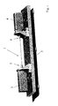
- a two-mass test bench 1 for condition monitoring of bearings is shown.
- the two-mass test rig 1 mounted on a carrier 2, has two synchronous machines 3 and 4.
- the bearings 5 and 6 are to be checked for damage in the context of condition monitoring according to the invention.
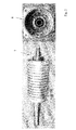
- the Fig. 2 shows the A-bearing 7 and the B-bearing 8 of the examined synchronous machines 3 and 4, which in the present case is the engine with the name DS 71 from Baumüller in Nuremberg.
- the stump or stub (encoder) is referred to with the A-bearing 7, while the B-bearing 8 represents the transducer side.
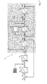
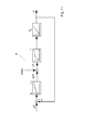
- the bearing damage diagnosis is carried out by means of a measurement in a closed speed control loop, the block diagram 9 in the Fig. 3 is shown.
- the block diagram 9 of Fig. 3 shows a closed speed control loop with mechanical dressing, as a dual mass oscillator in Circuit diagram is taken into account (cf. Fig. 1 ).
- the input of the closed speed control loop forms a predetermined speed setpoint or a setpoint angular speed ⁇ M * .
- a deviation from the nominal value, ⁇ M enters the controller parameterization as a control difference (proportional gain K P ), where T N denotes the controller parameter or the reset time.
- the pseudo-noise binary signal is added in addition to the output signal of the proportional integral speed controller (PI speed controller).
- i q * denotes the setpoint for the torque-forming component (iq) of the stator current.
- T si denotes a delay element with this time constant.
- the torque-forming component of the stator current i q is proportional to the drive torque m M , which is based on the nominal torque M N. Another time component comes through the ramp-up of the engine T M into play.
- ⁇ M denotes the motor angular velocity with reference to the nominal mechanical angular velocity ⁇ N.
- D denotes a normalized material damping of the spring; d thus represents a correction factor for the parameter fitting.
- the normalized spring constant is denoted by T C , T L indicates the acceleration time of the load.
- the spring moment is m F denotes the load torque with m L.
- the output forms the load angle velocity ⁇ L relative to the nominal mechanical angular velocity, ⁇ N.
- the system is excited by means of a pseudo-noise binary signal.
- the Welch method is preferably used according to the invention.
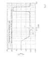
- the Fig. 4 shows an amplitude response 10 of a defect-free dual-mass oscillator and an amplitude response 11 of a dual-mass oscillator with damaged A-bearing of the prime mover.
- the amplitude responses 10, 11 the magnitude
- the input quantity û is 1A.
- the measurement refers to the A-bearing of a DS 71 engine, whereby a bearing was used as a defective bearing from the backware of a repair shop.
- the associated phase responses are in the Fig. 5 shown.
- the phase response 12 is the phase response at damaged bearing, the phase response 13 of the reference phase of the defect-free drive train.
- the deviation occurs in the phase response of the transfer function of the mechanical system G mech as expected in the range of the characteristic frequency of 12 Hz.
- the input quantity û is once again 1A.
- a targeted choice of the amplitude of the pseudo-noise binary signal an optimization of the traces can be achieved in such a way that bearing damage by a better expression of the deviations with regard to the respective reference curves are better to recognize.
- This better recognizability is also in the phase transition 20 of the defective dual mass oscillator compared to the phase response 21 of the defect-free dual mass oscillator, as in the Fig. 7 shown below.
- a deviation of the amplitude response 22 in the presence of a defect compared to the amplitude response 23 without defect can be seen.
- Fig. 9 the frequency response of a defect-free dual-mass oscillator and a dual-mass vibrator with damaged B-bearing of the prime mover is shown.
- f AR 10 Hz for the outer race.
- a significant deviation compared to the amplitude response 27 for the case of a defect-free bearing can be seen.
- a deviation always occurs between the currently measured frequency response of the damaged drive train and a reference frequency response as an indicator. The results are well reproducible.
- a frequency response is shown with a tolerance band around a reference curve.
- tolerance values or a tolerance band By specifying tolerance values or a tolerance band, automated error detection is possible.
- the tolerance bands 30 and 31 include the reference curve 32.
- a measured amplitude response 33 results, in which the tolerance range which is predetermined by the upper tolerance band 30 and the lower tolerance band 31 is left.
- a suitable algorithm searches in the range in particular for the characteristic error frequencies after such a deviation both in the amplitude and in the phase response. Accordingly, as in the Fig.
- an upper tolerance band 34 and a lower tolerance band 35 are also defined for the phase response.
- the two tolerance bands 34 and 35 surround the phase response of the defect-free system, which is designated here by the reference numeral 36. If a bearing damage is present, a phase transition 37 results, in which the region bounded by the tolerance bands 34 and 35 is clearly left here.
- a measurement configuration 38 for a measurement on a mechanically idling machine is shown.
- a setpoint value ⁇ * for the angular velocity is specified.
- K Pn denotes the proportional gain (controller parameter), T Nn the reset time or the corresponding controller parameter.
- PRBS pseudo-noise binary signal
- the torque setpoint is represented in the measurement configuration 38 as m i * .
- T s denotes a replacement time constant of the closed loop, T M again the ramp-up time of the motor.
- Output signal of the measurement configuration is the motor angular velocity ⁇ .
- s jw represents the complex angular frequency
- ⁇ M represents the motor angular velocity
- i q represents the torque-forming current component
- J M represents the moment of inertia of the motor.
- the phase is at the beginning at 0 ° and then goes to -90 °, since in a real system, no ideal integrator is given, but the system or the machine behaves in the range of very low frequencies as a VZ1-member, so as a Delay element of the first order.
- the Fig. 12 finally shows measurement results of a measurement on a mechanically idling machine, on the one hand, the amplitude response 39, on the other hand, the phase response 40 is shown.
- phase transition 40 three peaks can be seen which represent a deviation from the expected course and thus indicate a bearing damage as an indicator. These peaks are at the expected locations, namely at frequencies around 11 Hz and multiples thereof, namely 22 and 33 Hz.
- the measurement on an idling machine allows the measurement in the test field or repair shop to investigate whether bearing damage is present , Disassembly of the machine is not required.
Abstract
Description
Die Erfindung betrifft ein Verfahren zur Zustandsüberwachung bei im Rahmen eines mechanischen Antriebsverbunds bestimmte Funktionen erfüllenden Lagern permanenterregter Synchronmaschinen sowie eine zugehörige Einrichtung zur Zustandsüberwachung für im Rahmen eines mechanischen Antriebsverbunds bestimmte Funktionen erfüllende Lager permanenterregter Synchronmaschinen.The invention relates to a method for condition monitoring in fulfilling certain functions of permanent mechanical synchronous machines in the context of a mechanical drive network as well as an associated device for condition monitoring for bearings of permanent-magnet synchronous machines fulfilling specific functions within the framework of a mechanical drive network.
Innerhalb eines mechanischen Antriebsverbunds gibt es in aller Regel eine Mehrzahl von Lagern, die, beispielsweise aufgrund von Verschleißerscheinungen, fehlerhaft sein können bzw. Schäden aufweisen. In der Tat ist die häufigste Ursache für den Ausfall von elektrischen Maschinen in Produktionsanlagen ein Defekt in einem Maschinenlager. Andere Schäden sind gegenüber dem Problem der Lager von sekundärer Bedeutung.Within a mechanical drive system, there are usually a plurality of bearings which, for example because of signs of wear, may be faulty or have damage. In fact, the most common cause of the failure of electrical machines in production facilities is a defect in a machinery warehouse. Other damages are secondary to the problem of bearings.
Daher wurden im Stand der Technik bereits verschiedene Verfahren entwickelt, mit denen eine Diagnostik von Lagerschäden möglich ist und die auf Messungen unterschiedlicher physikalischer Größen basieren.Therefore, various methods have already been developed in the prior art, with which a diagnosis of bearing damage is possible and based on measurements of different physical sizes.
Beispielsweise gibt es vibrationsbasierte Verfahren, bei denen Lagerfehler anhand der gemessenen Maschinenvibration detektiert werden. Diese Verfahren weisen eine gute Genauigkeit auf und sind geeignet, Fehler frühzeitig zu erkennen. Die Schwingungen können durch Vibrationssensoren, z. B. am Lagergehäuse, aufgezeichnet werden. Insbesondere eignen sich der Schwingweg, die Schwinggeschwindigkeit oder die Schwingbeschleunigung als Messgrößen. Beispielhaft zu nennen für die Vibrationsanalyse sind die Darstellungen in verschiedenen Forschungsarbeiten von J. R. Stack, R. G. Harley und T. G. Habetler. Der Einsatz von Beschleunigungssensoren zur Vibrationsdetektion ist allerdings sehr kostspielig, wie von M. Blödt in der Doktorarbeit "Condition monitoring of mechanical faults in variable speed induction motor drives. Application of stator current time-frequency analysis and parameter estimation" dargestellt (Institut National de Polytechnique de Toulouse, France, 2006). Diese Art der Fehlerdiagnose ist daher vorrangig nur für den Einsatz in sicherheitsrelevanten Anlagen geeignet, so dass im Hinblick auf die Wirtschaftlichkeit nach alternativen Strategien gesucht werden muss, bei denen eine weniger aufwendige Sensorik erforderlich ist.For example, there are vibration-based methods in which bearing failures are detected based on the measured machine vibration. These methods have good accuracy and are capable of detecting errors early. The vibrations can be detected by vibration sensors, eg. B. on the bearing housing, recorded. In particular, the vibration travel, the vibration velocity or the vibration acceleration are suitable as measured variables. To give an example for the vibration analysis are the representations in various research by JR Stack, RG Harley and TG Habetler. However, the use of acceleration sensors for vibration detection is very costly, as described by M. Blödt in the doctoral thesis "Condition monitoring of mechanical faults in variable speed induction motor drives. Application of stator current time-frequency analysis and parameter estimation "(Institut National de Polytechnique de Toulouse, France, 2006.) This type of fault diagnosis is therefore primarily suitable for use in safety-relevant installations, so that in terms of cost-effectiveness alternative strategies must be sought, in which a less expensive sensor technology is required.
Desweiteren gibt es die Diagnose durch Messung von Körperschall, die darauf basiert, dass mechanische Fehler außer Vibrationen auch eine erhöhte Geräuschemission verursachen (vgl. hierzu beispielsweise
Weiterhin existiert eine Diagnosetechnik zur Erkennung von Motorfehlern durch Messung der Maschinenströme, kurz als "MCSA" für "Motor current signatur analysis" bezeichnet. Der Vorteil der MCSA gegenüber der Vibrationsanalyse besteht darin, dass keine kostspieligen Sensoren erforderlich sind (vergleiche hierzu beispielsweise
Ein weiteres Verfahren stellt die Lagerüberwachung durch Temperaturmessung dar, die davon ausgeht, dass bei einer Erhöhung der Reibung im Lager die Temperatur gegenüber der normalen Betriebstemperatur ansteigt (vgl. hierzu
Schließlich ist die Lagerüberwachung durch Ölpartikelanalyse zu nennen, bei der eine Analyse des Schmiermittels durchgeführt wird. Ein in den Ölkreislauf integrierter Sensor misst die Menge der Verschleißpartikel im Schmierstoff. Dieses Verfahren wird allerdings nur bei besonders kritischen Anwendungen bzw. in Sonderfällen verwendet (vgl. das bereits genannte Handbuch "Die Wälzlagerpraxis" sowie den Artikel von Thorsen und Dalva).Finally, bearing monitoring by means of oil particle analysis, in which an analysis of the lubricant is carried out. A sensor integrated into the oil circuit measures the amount of wear particles in the lubricant. However, this procedure is only used for particularly critical applications or in special cases (see the previously mentioned manual "The Bearing Practice" as well as the article by Thorsen and Dalva).
Der Erfindung liegt damit die Aufgabe zugrunde, ein diesbezüglich verbessertes Verfahren zur Zustandsüberwachung bei ihm Rahmen eines mechanischen Antriebsverbunds bestimmte Funktionen erfüllenden Lagern permanenterregter Synchronmaschinen anzugeben.The invention is thus based on the object of specifying an improved method of condition monitoring in this context of a mechanical drive network of bearings of permanently excited synchronous machines which fulfill certain functions.
Zur Lösung dieser Aufgabe ist erfindungsgemäß ein solches Verfahren vorgesehen, dass sich dadurch auszeichnet, dass die Zustandsüberwachung antriebsbasiert mittels wenigstens einer Frequenzganganalyse durchgeführt wird.To achieve this object, such a method is provided according to the invention that is characterized in that the condition monitoring is carried out drive-based by means of at least one frequency response analysis.
Im erfindungsgemäßen Kontext ist dabei der Begriff "Zustandsüberwachung" in einem sehr breiten Sinne zu verstehen. Das Verfahren erfasst neben dem "Condition monitoring" im eigentlichen Sinne selbstverständlich ebenso die übliche Fehlerdetektion und Diagnose mit den einzelnen im Rahmen der Diagnose durchzuführenden Schritten wie der Signalaufnahme, Auswertung und dergleichen. Das Verfahren bezieht sich auf permanenterregte Synchronmaschinen, bei denen Permanentmagnete zur Felderzeugung dienen.In the context according to the invention, the term "condition monitoring" is to be understood in a very broad sense. In addition to the "condition monitoring" in the actual sense, the method naturally also includes the usual error detection and diagnosis with the individual steps to be performed in the context of the diagnosis, such as signal acquisition, evaluation and the like. The method relates to permanent magnet synchronous machines in which permanent magnets are used for field generation.
Die vorliegende Erfindung stellt einen Beitrag zur Entwicklung zustandsorientierter Instandhaltung von Anlagen mit Antriebsverbünden dar, also von Anlagen, die mit elektrischer Antriebstechnik ausgerüstet sind. Die Zustandsüberwachung betrifft Lager, die im Kontext des mechanischen Antriebsverbunds bestimmte Funktionen aufweisen. Diese Lager sind somit im Hinblick auf bestimmte Aufgaben in den mechanischen Antriebsverbund integriert. Die erfindungsgemäße Zustandsüberwachung findet antriebsbasiert statt, also bezogen auf die einzelnen Antriebe des Verbunds bzw. ausgehend von Regel- bzw. Steuereinheiten für die jeweiligen Antriebe. Zur Zustandsüberwachung wird eine Frequenzganganalyse durchgeführt. Selbstverständlich liegt es ebenso im Rahmen der Erfindung, zur Zustandsüberwachung mehrfach Frequenzganganalysen durchzuführen, zum Beispiel mit unterschiedlichen Eingangsdaten bzw. kontinuierlich oder in bestimmten Zeitabschnitten, um so durch eine fortlaufende Überwachung zuverlässig Lagerfehler auffinden zu können. Frequenzganganalysen können auch gezielt bei Änderungen im System oder Anzeichen für Fehler vorgenommen bzw. wiederholt werden. Die erfindungsgemäße Zustandsüberwachung basiert somit auf der Aufnahme und Auswertung von Daten einer oder mehrerer Frequenzganganalysen.The present invention contributes to the development of condition-based maintenance of plants with drive networks, that is, of plants that are equipped with electrical drive technology. The condition monitoring concerns bearings which have certain functions in the context of the mechanical drive system. These bearings are thus integrated with regard to specific tasks in the mechanical drive system. The state monitoring according to the invention takes place on the basis of the drive, that is, based on the individual drives of the network or starting from control or control units for the respective drives. For condition monitoring, a frequency response analysis is performed. Of course, it is also within the scope of the invention to repeatedly perform frequency response analyzes for condition monitoring, for example, with different input data or continuously or in certain time periods, so as to be able to reliably detect bearing errors by means of continuous monitoring. Frequency response analyzes can also be made or repeated specifically for changes in the system or signs of errors. The condition monitoring according to the invention is thus based on the recording and evaluation of data of one or more frequency response analyzes.
Mit einer Frequenzganganalyse lässt sich eine Zustandsüberwachung mit besonderem Vorteil problemlos auch bei Synchronmaschinen durchführen, bei denen der Luftspalt im Vergleich zu Asynchronmaschinen deutlich größer ist. Das Prinzip einer Frequenzgangmessung zur Diagnose von Lagerschäden wurde zwar bereits in der Dissertation von S. Villwock mit dem Titel "Identifikationsmethoden für die automatisierte Inbetriebnahme und Zustandsüberwachung elektrischer Antriebe", Universität Siegen, 2007, durchgeführt, die dort beschriebene Vorgehensweise betraf allerdings auf rein akademischer Ebene lediglich Lager, die zusätzlich in einen mechanischen Antriebsstrang installiert worden waren und im mechanischen Verband keinerlei Funktion besaßen. Des weiteren finden sich in diesem Dokument keinerlei Hinweise, die Zustandsüberwachung antriebsbasiert durchzuführen, also mit engem Bezug zu den Regelungs- bzw. Steuerungseinrichtungen für die einzelnen Antriebe. Der Bezug zum einzelnen Antrieb stellt aber eine grundlegende Weiterentwicklung für die praktische Nutzbarkeit der Frequenzanalyse dar.With a frequency response analysis, condition monitoring can be carried out with particular advantage without problems even in synchronous machines in which the air gap is significantly larger in comparison to asynchronous machines. The principle of frequency response measurement for the diagnosis of bearing damage has already been described in The dissertation by S. Villwock titled "Identification methods for automated commissioning and condition monitoring of electric drives", University of Siegen, 2007, carried out, but the procedure described there on a purely academic level was only bearings, which were also installed in a mechanical drive train and had no function in the mechanical bandage. Furthermore, there are no indications in this document of performing state monitoring on a drive-based basis, that is, with close reference to the control or regulating devices for the individual drives. However, the relation to the individual drive represents a fundamental further development for the practical usability of the frequency analysis.
Die erfindungsgemäße Zustandsüberwachung kann für Wälzlager, insbesondere für rotierende und/oder translatorische Wälzlager, und/oder für einen Antriebsverbund einer Maschinenbauanlage und/oder einer Druckmaschine, insbesondere einer Zeitungsdruckanlage, durchgeführt werden. Die Erfindung ermöglicht also beispielsweise die Überwachung der Wälzlager der Antriebsmaschinen bei Zeitungsdruckanlagen usw.The condition monitoring according to the invention can be carried out for rolling bearings, in particular for rotating and / or translatory rolling bearings, and / or for a drive assembly of a mechanical engineering plant and / or a printing press, in particular a newspaper printing press. The invention thus enables, for example, the monitoring of the rolling bearings of the drive machines in newspaper printing systems, etc.
Die Zustandsüberwachung mittels Frequenzganganalyse kann anhand von und/oder ausschließlich mittels wenigstens einer in wenigstens einem Antriebsregelgerät des Antriebsverbunds standardmäßig verfügbaren Information durchführt werden, insbesondere mittels einer, gegebenenfalls aus zwei Phasenströmen berechneten, drehmomentbildenden Komponente eines Statorstroms und/oder mittels einer motorseitig gemessenen Rotorposition und/oder eines Motordrehzahlistwertssignals.Condition monitoring by means of frequency response analysis can be performed by means of and / or exclusively by means of at least one information available in at least one drive controller of the drive network, in particular by means of a torque-forming component of a stator current calculated optionally from two phase currents and / or by means of a rotor position measured on the motor side and / or or an engine speed actual value signal.
Das erfindungsgemäße Verfahren geht so (mit besonderem Vorteil ausschließlich) von Informationen aus, die in einem Antriebsregelgerät oder dergleichen ohnehin verfügbar sind. Hierzu zählen die drehmomentbildende Komponente des Statorstroms iq(t) und die motorseitig gemessene Rotorposition ΦM(t) bzw. das daraus abgeleitete Motordrehzahlistwertsignal (ΩM(t) = dΦM/dt bzw. nM(t)). Damit kann auf eine zusätzliche, unter Umständen kostspielige, aufwändige bzw. störanfällige Sensorik verzichtet werden.The method according to the invention proceeds (with particular advantage exclusively) from information which is available anyway in a drive controller or the like. These include the torque-forming component of the stator current iq (t) and the rotor-side measured rotor position Φ M (t) or derived therefrom Motordrehzahlistwertsignal (Ω M (t) = dΦ M / dt or n M (t)). This can be dispensed with an additional, possibly expensive, expensive or fault-prone sensors.
Im Rahmen der erfindungsgemäßen Zustandsüberwachung kann der aktuelle Zustand von Lagern ermittelt werden und/oder die Zustandsüberwachung kann für A-Lager und/oder B-Lager von permanenterregten Synchronmaschinen durchgeführt werden. Erfindungsgemäß kann somit beispielsweise der aktuelle Lagerzustand überwacht werden, indem Messungen in bestimmten Zeitabständen oder kontinuierlich bzw. bei Anzeichen für Probleme durchgeführt werden. Die Messungen können sowohl für A-Lager (also für die Stumpf- bzw. Stummelseite) als auch für den B-Teil der Lager, also die Geberseite, durchgeführt werden. Insgesamt ist durch die erfindungsgemäße Zustandsüberwachung eine Vermeidung, zumindest jedoch eine signifikante Verringerung von ungeplanten Anlagenstillständen in Folge von Lagerschäden erreichbar. Somit ergibt sich als technischer Vorteil zum Beispiel eine Reduktion der sogenannten Life-Cycle-Costs bzw. eine Optimierung der Wartungskosten, da durch das Condition Monitoring eine optimierte Ausnutzung des Verschleißvorrats der Maschinenelemente möglich ist. Die Maschinenelemente werden also weder zu früh noch zu spät ausgetauscht bzw. erneuert.As part of the condition monitoring according to the invention, the current state of bearings can be determined and / or the condition monitoring can be carried out for A-bearings and / or B-bearings of permanent-magnet synchronous machines. Thus, according to the invention, for example, the current storage condition can be monitored, for example, by carrying out measurements at specific time intervals or continuously or with indications of problems. The measurements can be carried out both for A bearings (ie for the butt and stub side) and for the B part of the bearings, ie the encoder side. Overall, the condition monitoring according to the invention avoids avoidance, but at least a significant reduction, of unplanned plant shutdowns as a result of bearing damage. Thus, a technical advantage, for example, results in a reduction of the so-called life-cycle costs or an optimization of the maintenance costs, since an optimized utilization of the wear reserve of the machine elements is possible by condition monitoring. The machine elements are therefore neither replaced too early nor too late or renewed.
Die Zustandsüberwachung kann mittels einer integriert in einem Antriebsregler und/oder digitalen Signalprozessor und/oder Umrichter implementierten Funktion durchgeführt werden. Die Zustandsüberwachung findet in einem solchen Fall in dem Sinne antriebsbasiert statt, dass die Methode zur Überwachung des Zustands der Lager als integrierte Condition-Monitoring-Funktion in den Umrichtern bzw. Antriebsreglern oder Signalprozessoren implementiert ist, die den jeweiligen Antrieben zugehörig bzw. zugeordnet sind. Damit ist eine praxisnahe Realisierung der Zustandsüberwachung möglich.The condition monitoring can be carried out by means of a function implemented in an integrated manner in a drive controller and / or digital signal processor and / or converter. The condition monitoring takes place in such a case in the sense of drive-based that the method for monitoring the state of the bearings is implemented as an integrated condition monitoring function in the drives or drive controllers or signal processors that are associated with the respective drives. Thus, a practical realization of condition monitoring is possible.
In die Zustandsüberwachung kann eine Überprüfung auf geringfügige und/oder aus einem realen Betrieb bekannte Lagerschäden integriert werden bzw. die Zustandsüberwachung kann eine solche Überprüfung umfassen. Dies bedeutet, dass die erfindungsgemäße Zustandsüberwachung nicht nur für schwer beschädigte bzw. künstlich beschädigte Lager möglich ist, sondern dass mit dem erfindungsgemäßen Verfahren zum Beispiel bereits eine Diagnose sich anbahnender Schäden ermöglicht wird. Reale, zum Teil nur leicht beschädigte Lager können so bei der Zustandsüberwachung im Hinblick auf mögliche Schäden oder sich anbahnende Schäden richtig eingeordnet werden.In the condition monitoring, a check for minor and / or known from a real operation bearing damage can be integrated or condition monitoring can include such a review. This means that the condition monitoring according to the invention is not only possible for severely damaged or artificially damaged bearings, but that, for example, the method according to the invention already makes it possible to diagnose imminent damage. Real, sometimes only light Damaged bearings can thus be correctly classified in the condition monitoring with regard to possible damage or imminent damage.
Die Zustandsüberwachung kann unter Berücksichtigung der bzw. wenigstens einer Beziehung zwischen der Amplitude des Anregungssignals für die Frequenzganganalyse und der Ausprägung wenigstens eines auf den Lagerzustand hinweisenden Indikators und/oder unter Optimierung der Amplitude des Anregungssignals für die Frequenzganganalyse im Hinblick auf die Ausprägung wenigstens eines auf den Lagerzustand hinweisenden Indikators durchgeführt werden.The condition monitoring may take into consideration the or at least one relationship between the amplitude of the excitation signal for the frequency response analysis and the expression of at least one indicative of the storage condition indicator and / or optimizing the amplitude of the excitation signal for the frequency response analysis with regard to the expression of at least one of the Storage condition indicative indicator can be performed.
Dies bedeutet, dass beim erfindungsgemäßen Verfahren gezielt die Amplitude des Anregungssignals so gewählt wird, dass bestimmte, auf den Lagerzustand hinweisende Indikatoren wie besondere Abweichungen, Ausschläge oder dergleichen beispielsweise von einer Referenzkurve gut erkennbar und diagnostizierbar sind. Je ausgeprägter der Indikator beispielsweise in einem Bode-Diagramm erkennbar ist, bei dem ein Graph für den Betrag, also die Amplitudenverstärkung, und ein Graph für das Argument, die Phasenverschiebung, aufgetragen wird, desto zuverlässiger kann die Lagerschadendiagnostik durchgeführt werden.This means that in the method according to the invention, the amplitude of the excitation signal is specifically selected so that certain indicative of the storage condition indicators such as special deviations, rashes or the like, for example, from a reference curve are easily recognizable and diagnosable. The more pronounced the indicator can be seen, for example, in a Bode diagram in which a graph for the amount, that is, the amplitude gain, and a graph for the argument, the phase shift, is plotted, the more reliable the bearing damage diagnostics can be performed.
Die Zustandsüberwachung kann mittels einer Messung in einem geschlossenen Drehzahlregelkreis und/oder unter Betrachtung des mechanischen Antriebsverbunds als Zweimassenschwinger durchgeführt werden. Im geschlossenen Drehzahlregelkreis können beispielsweise die Rotorposition der Antriebsmaschine und Zweiphasenströme, aus denen die drehmomentbildende Komponente des Statorstroms berechnet wird, gemessen werden. Der mechanische Verband kann im Drehzahlregelkreis als Zweimassenschwinger berücksichtigt sein. Auf diese Art und Weise können spezifische Prüfstandsbedingungen vorgegeben werden.The condition monitoring can be carried out by means of a measurement in a closed speed control loop and / or considering the mechanical drive network as a two-mass oscillator. In the closed speed control loop, for example, the rotor position of the drive machine and two-phase currents, from which the torque-forming component of the stator current is calculated, can be measured. The mechanical bond can be taken into account in the speed control loop as a two-mass oscillator. In this way, specific test bench conditions can be specified.
Das System des mechanischen Antriebsverbunds kann zur Frequenzganganalyse mittels eines Pseudo-Rausch-Binär-Signals (PRBS) angeregt werden und/oder im Rahmen der Frequenzganganalyse kann zur Verarbeitung der Messsignale die Welch-Methode verwendet werden.The mechanical drive system can be used for frequency response analysis using a Pseudo-Noise Binary Signal (PRBS) are excited and / or in the context of the frequency response analysis, the Welch method can be used to process the measurement signals.
Die Welch-Methode dient bei der Verarbeitung der Messsignale dazu, die Signalstärke im Hinblick auf die Frequenz abzuschätzen. Dabei steht eine Reduzierung des Rauschens im Vordergrund.The Welch method, when processing the measurement signals, is used to estimate the signal strength in terms of frequency. Here, a reduction of the noise in the foreground.
Bei der Frequenzganganalyse kann als auf den Lagerzustand hinweisender Indikator wenigstens eine für einen Lagerschaden charakteristische Frequenz und/oder Veränderung um den Bereich wenigstens einer charakteristischen Frequenz und/oder wenigstens eine Veränderung um den Bereich wenigstens einer Vielfachen einer charakteristischen Frequenz im Frequenzgang berücksichtigt werden und/oder es können im Rahmen einer Auswertung eines Frequenzgangs ein Referenzfrequenzgang und/oder Toleranzvorgaben verwendet werden und/oder es kann ein Algorithmus zur Erkennung von Abweichungen von einem Referenzfrequenzgang verwendet werden und/oder es kann im Rahmen der Frequenzganganalyse ein Amplituden- und/oder Phasengang betrachtet werden.In the frequency response analysis, at least one characteristic of a bearing damage frequency and / or change by the range of at least one characteristic frequency and / or at least one change to the range of at least a multiple of a characteristic frequency in the frequency response can be taken into account and / or as indicative of the storage condition a reference frequency response and / or tolerance specifications can be used in the course of an evaluation of a frequency response and / or an algorithm for detecting deviations from a reference frequency response can be used and / or an amplitude and / or phase response can be considered within the frequency response analysis ,
Erfindungsgemäß können somit zur Indikation, in welchem Zustand sich ein Lager befindet, beispielsweise charakteristische Fehlerfrequenzen herangezogen werden. Diese lassen sich berechnen. Beispielsweise gilt für die charakteristische Frequenz für eine Beschädigung des äußeren Laufrings eines Lagers 
wobei z die Anzahl der Wälzkörper des Lagers angibt,
Ω n die mechanische Winkelgeschwindigkeit des Antriebs darstellt,
dw den Wälzkörperdurchmesser angibt,
dk für den Käfigdurchmesser steht und
θ den Andrückwinkel wiedergibt.According to the invention can thus be used to indicate, for example, in which state a warehouse, for example, characteristic error frequencies. These can be calculated. For example, applies to the characteristic frequency for damage to the outer race of a bearing
where z indicates the number of rolling elements of the bearing,
Ω n represents the mechanical angular velocity of the drive,
d w indicates the rolling element diameter,
d k stands for the cage diameter and
θ represents the pressure angle.
Für den Innenring gilt entsprechend die Beziehung 
Charakteristische Fehlerfrequenzen beispielsweise für Kugellager mit acht bis zwölf Kugeln lassen sich auch anhand von Näherungsformeln berechnen, ohne dass eine Kenntnis der vorgenannten Parameter erforderlich wäre. Die entsprechenden Näherungsformeln lauten für den Außenring 
und für den Innenring 
and for the inner ring
Beispielsweise gelten für die Kugellager des DS71-Motors der Firma Baumüller die folgenden Kenndaten
(6205-2RSR-C3)
(6203-2Z-C3)
(6205-2RSR-C3)
(6203-2Z-C3)
Veränderungen um den Bereich der charakteristischen Frequenz(en) und deren Vielfacher im Frequenzgang weisen auf eine Beschädigung der Wälzlager hin. Bei einer geschickten Wahl der anregenden Amplitude für die Frequenzgangmessung lassen sich diese Indikatoren optimal erkennen und damit optimal auswerten.Changes around the range of the characteristic frequency (s) and their multiple in the frequency response indicate damage to the bearings. With a clever choice of the stimulating amplitude for the frequency response measurement, these indicators can be optimally recognized and thus optimally evaluated.
Mit einem entsprechenden Algorithmus, der beispielsweise von einem Referenzamplitudengang ausgeht, lassen sich gezielt Abweichungen im Amplitudengang erkennen. Ebenso kann ein geeigneter Algorithmus nach Abweichungen im Phasengang suchen. Dabei können gegebenenfalls Fehlertoleranzen, die noch akzeptabel sind, bzw. normal auftretende Abweichungen berücksichtigt werden.With a corresponding algorithm, for example starting from a reference amplitude response, it is possible to detect specific deviations in the amplitude response. Likewise, a suitable algorithm may look for deviations in the phase response. If necessary, error tolerances that are still acceptable or deviations that occur normally can be taken into account.
Im Rahmen der Zustandsüberwachung kann wenigstens eine Frequenzganganalyse an einer mechanisch leerlaufenden Synchronmaschine, insbesondere in einem Prüffeld und/oder Reparaturwerk und/oder ohne Demontage der Synchronmaschine, und/oder an einer Synchronmaschine mit einem im Vergleich zu einer Asynchronmaschine großen Luftspalt durchgeführt werden.As part of condition monitoring, at least one frequency response analysis on a mechanically idling synchronous machine, in particular in a test field and / or repair shop and / or without disassembly of the synchronous machine, and / or on a synchronous machine with a large compared to an asynchronous air gap can be performed.
Die Messung an einer leerlaufenden Maschine ermöglicht die Messung im Prüffeld, beispielsweise in einem Reparaturwerk, um zu untersuchen, ob ein Lagerschaden vorliegt, ohne dass eine Demontage der Maschine erforderlich wäre. Des Weiteren lässt sich die erfindungsgemäße Zustandsüberwachung bei Synchronmaschinen mit einem großen Luftspalt durchführen, ohne dass durch den Luftspalt Probleme bzw. Fehler bei der Diagnose auftreten würden. Dies stellt einen deutlichen Vorteil gegenüber einer Reihe bisher üblicher Diagnoseverfahren dar.The measurement on an idling machine allows the measurement in the test field, for example in a repair shop, to investigate whether a bearing damage is present without disassembly of the machine would be required. Furthermore, the condition monitoring according to the invention can be carried out in synchronous machines with a large air gap without problems or errors in the diagnosis occurring through the air gap. This represents a clear advantage over a number of previously common diagnostic methods.
Darüber hinaus betrifft die Erfindung eine Einrichtung zur Zustandsüberwachung für ihm Rahmen eines mechanischen Antriebsverbunds bestimmte Funktionen erfüllende Lager permanenterregter Synchronmaschinen, insbesondere nach einem Verfahren wie im Vorstehenden geschildert, die sich dadurch auszeichnet, dass die Einrichtung zur antriebsbasierten Zustandsüberwachung mittels wenigstens einer Frequenzganganalyse ausgebildet ist. Die Einrichtung weist also Mittel auf, um bei einem Motor bzw. einer permanent erregten Synchronmaschine eine Anregung beispielsweise mit einem Pseudo-Rausch-Binär-Signal vorzunehmen und die Signale, die sich aus dieser Anregung ergeben, aufzunehmen und auszuwerten. Dabei kann die Auswertung beispielsweise so erfolgen, dass Bode-Diagramme der Amplituden- und Phasengänge aus den Messdaten erzeugt werden, die dann beispielsweise mittels einer Recheneinrichtung, auf der entsprechende Funktionen bzw. Algorithmen implementiert sind, hinsichtlich spezifisch auf Lagerschäden hinweisender Indikatoren untersucht werden.Moreover, the invention relates to a device for condition monitoring for him frame of a mechanical drive network certain functions fulfilling bearing permanent-magnet synchronous machines, in particular by a method as described above, which is characterized in that the means for the drive-based condition monitoring is formed by at least one frequency response analysis. The device thus has means for making an excitation with a motor or a permanently excited synchronous machine, for example, with a pseudo-noise binary signal and record and evaluate the signals resulting from this excitation. In this case, the evaluation can be carried out, for example, such that Bode diagrams of the amplitude and phase responses are generated from the measurement data, which are then examined, for example, by means of a computing device, on which corresponding functions or algorithms are implemented, with respect to indicators specifically indicative of bearing damage.
Die Einrichtung zur Zustandsüberwachung kann zur Ermittlung und/oder Auswertung von in wenigstens einem Antriebsregelgerät des Antriebsverbunds standardmäßig verfügbaren Informationen, insbesondere zur Ermittlung und/oder Auswertung einer, gegebenenfalls aus zwei Phasenströmen berechneten, drehmomentbildenden Komponente eines Statorstroms und/oder einer motorseitig gemessenen Rotorposition und/oder eines Motordrehzahlistwerts, und/oder des aktuellen Zustands von Lagern ausgebildet sein. Vorteilhafterweise werden somit von der Einrichtung Informationen genutzt, die ohnehin in den Antriebsregelgeräten gesammelt werden bzw. in diesen bereits vorliegen. Insbesondere ist es möglich, dass die Einrichtung die Zustandsüberwachung lediglich auf Basis solcher bereits vorhandener Informationen durchführt, sodass keine zusätzlichen Sensoren erforderlich sind und keine weiteren spezifischen Messwerte aufgenommen und verarbeitet werden müssen, wodurch insgesamt Kosten und Aufwand niedrig gehalten werden können.The device for state monitoring can be used for determining and / or evaluating information available in at least one drive controller of the drive network, in particular for determining and / or evaluating a torque-forming component of a stator current and / or a rotor-side measured rotor position and / or an optionally calculated from two phase currents. or one Engine speed actual value, and / or the current state of bearings be formed. Advantageously, the device thus uses information that is already collected in the drive controllers or is already present in the drive controllers. In particular, it is possible for the device to perform the condition monitoring only on the basis of such already existing information, so that no additional sensors are required and no further specific measured values have to be recorded and processed, whereby overall costs and effort can be kept low.
Die Einrichtung kann wenigstens eine integriert in einem Antriebsregler und/oder digitalen Signalprozessor und/oder Umrichter implementierte Funktion umfassen und/oder die Einrichtung kann zur Überprüfung auf geringfügige und/oder aus einem realen Betrieb bekannte Lagerschäden und/oder zur Berücksichtigung der Beziehung zwischen der Amplitude des Anregungssignals für die Frequenzganganalyse und der Ausprägung wenigstens eines auf den Lagerzustand hinweisenden Indikators und/oder zur Optimierung der Amplitude des Anregungssignals für die Frequenzganganalyse im Hinblick auf die Ausprägung wenigstens eines auf den Lagerzustand hinweisenden Indikators ausgebildet sein.The device may comprise at least one function implemented integrated in a drive controller and / or digital signal processor and / or converter and / or the device may be used to check for minor and / or real-time storage damage and / or to take account of the relationship between the amplitude the excitation signal for the frequency response analysis and the expression of at least one indicative of the storage condition indicator and / or for optimizing the amplitude of the excitation signal for the frequency response analysis with regard to the expression of at least one indicative of the storage condition indicator.
Vorzugsweise wird die erfindungsgemäße Zustandsüberwachung in antriebsbezogene Vorrichtungen wie beispielsweise die Umrichter implementiert, so dass keine zusätzliche Hardware erforderlich ist. Die Zustandsüberwachungseinrichtung ist also dann Bestandteil einer bzw. mehrerer Komponenten des Antriebsverbunds bzw. in ein Antriebssystem integriert. Die Einrichtung kann Auswerte- bzw. Rechenmittel aufweisen, um z.B. die Anregung im Rahmen der Frequenzganganalyse im Hinblick auf das Indikatorsignal zu optimieren. Zu diesem Zweck kann gegebenenfalls eine wiederholte Anregung des zu prüfenden Systems erfolgen, wobei das erhaltene Signal beispielsweise im Rahmen einer Regelung überprüft wird, um schließlich eine optimale Anregung zu finden, damit der Indikator für den Lagerzustand hinreichend bzw. besonders gut ausgebildet ist.Preferably, the condition monitoring according to the invention is implemented in drive-related devices, such as the inverters, so that no additional hardware is required. The condition monitoring device is then part of one or more components of the drive network or integrated into a drive system. The device may have evaluation or computing means, for example, to optimize the excitation in the context of the frequency response analysis with regard to the indicator signal. If necessary, repeated excitation of the system to be tested can take place for this purpose, with the signal obtained being checked, for example, in the context of closed-loop control in order finally to find an optimum excitation so that the indicator for the storage condition is sufficiently or particularly well designed.
Die Einrichtung kann zur Zustandsüberwachung mittels einer Messung in einem geschlossen Drehzahlregelkreis und/oder unter Betrachtung des mechanischen Antriebsverbunds als Zweimassenschwinger und/oder zur Anregung des Systems des mechanischen Antriebsverbunds zur Frequenzganganalyse mittels eines Pseudo-Rausch-Binär-Signals und/oder im Rahmen der Frequenzganganalyse zur Verwendung der Welch-Methode zur Verarbeitung der Messsignale ausgebildet sein.The device can be used to condition monitoring by means of a measurement in a closed speed control loop and / or considering the mechanical drive network as a dual mass oscillator and / or to excite the system of the mechanical drive network for frequency response analysis by means of a pseudo-noise binary signal and / or in the context of frequency response analysis be designed to use the Welch method for processing the measurement signals.
Weitere Vorteile, Merkmale und Einzelheiten der Erfindung ergeben sich anhand der folgenden Ausführungsbeispiele sowie aus den Zeichnungen. Dabei zeigen:
-
Fig. 1 einen Zweimassenprüfstand zur Zustandsüberwachung gemäß einem erfindungsgemäßen Verfahren, -
Fig. 2 ein A- und B-Lager einer auf Beschädigungen zu prüfenden Antriebsmaschine, -
Fig. 3 ein Blockschaltbild eines geschlossenen Drehzahlregelkreises mit mechanischem Verbund, -
Fig. 4 einen Amplitudengang eines defektfreien Zweimassenschwingers und eines Zweimassenschwingers mit beschädigtem A-Lager der Antriebsmaschine, -
Fig. 5 einen Phasengang eines defektfreien Zweimassenschwingers und eines Zweimassenschwingers mit beschädigtem A-Lager der Antriebsmaschine, -
Fig. 6 einen Frequenzgang eines defektfreien Zweimassenschwingers und eines Zweimassenschwingers mit beschädigtem A-Lager der Antriebsmaschine, -
Fig.7 einen Frequenzgang mit im Vergleich zurFig. 6 halbierter Amplitude des Pseudo-Rausch-Binär-Signals, -
Fig. 8 einen weiteren Frequenzgang, -
Fig. 9 einen Frequenzgang eines defektfreien Zweimassenschwingers und eines Zweimassenschwingers mit beschädigtem B-Lager der Antriebsmaschine, -
Fig. 10 einen Frequenzgang mit einem Toleranzband um eine Referenzkurve, -
Fig. 11 eine Messkonfiguration für eine Messung an einer mechanisch leerlaufenden Maschine und -
Fig. 12 Messergebnisse einer Messung an einer mechanisch leerlaufenden Maschine.
-
Fig. 1 a dual-mass test stand for condition monitoring according to a method according to the invention, -
Fig. 2 an A and B bearing of an engine to be tested for damage, -
Fig. 3 a block diagram of a closed speed control loop with mechanical composite, -
Fig. 4 an amplitude response of a defect-free two-mass oscillator and a two-mass oscillator with damaged A-bearing of the prime mover, -
Fig. 5 a phase response of a defect-free two-mass oscillator and a two-mass oscillator with damaged A-bearing of the prime mover, -
Fig. 6 a frequency response of a defect-free two-mass oscillator and a two-mass oscillator with damaged A-bearing of the prime mover, -
Figure 7 a frequency response compared to theFig. 6 halved amplitude of the pseudo-noise binary signal, -
Fig. 8 another frequency response, -
Fig. 9 a frequency response of a defect-free two-mass oscillator and a two-mass oscillator with damaged B-bearing of the prime mover, -
Fig. 10 a frequency response with a tolerance band around a reference curve, -
Fig. 11 a measurement configuration for a measurement on a mechanically idling machine and -
Fig. 12 Measurement results of a measurement on a mechanically idling machine.
In der
Die
Die Lagerschadendiagnose erfolgt mittels einer Messung in einem geschlossenen Drehzahlregelkreis, der im Blockschaltbild 9 in der
Um den Frequenzgang Gmech(jω) des mechanischen Verbands zu messen, wird das System mit Hilfe eines Pseudo-Rausch-Binär-Signals angeregt. Zur Verarbeitung der Messsignale wird erfindungsgemäß vorzugsweise die Welch-Methode verwendet.To measure the frequency response G mech (jω) of the mechanical band, the system is excited by means of a pseudo-noise binary signal. For processing the measurement signals, the Welch method is preferably used according to the invention.
Die
Der Amplitudengang 11 des beschädigten Lagers zeigt die erwartete Abweichung bei der charakteristischen Frequenz fAR = 12 Hz.The
Die zugehörigen Phasengänge sind in der
In der
Für die Auswertung im Rahmen der Fehlerdiagnose wäre es wünschenswert, wenn die Ausprägung des Indikators noch deutlicher wäre. Um dies zu erreichen, wurde bei der
Die
In der
In der
In der 
wobei s = jw die komplexe Kreisfrequenz darstellt, ωM die Motorwinkelgeschwindigkeit angibt, iq für die drehmomentbildende Stromkomponente steht und JM das Trägheitsmoment des Motors darstellt.In the
where s = jw represents the complex angular frequency, ω M represents the motor angular velocity, i q represents the torque-forming current component, and J M represents the moment of inertia of the motor.
Die Phase liegt am Anfang bei 0° und geht dann auf -90°, da in einem realen System kein idealer Integrator gegeben ist, sondern sich das System bzw. die Maschine im Bereich sehr niedriger Frequenzen wie ein VZ1-Glied verhält, also wie ein Verzögerungsglied erster Ordnung.The phase is at the beginning at 0 ° and then goes to -90 °, since in a real system, no ideal integrator is given, but the system or the machine behaves in the range of very low frequencies as a VZ1-member, so as a Delay element of the first order.
Die
- 11
- ZweimassenprüfstandTwo ground test
- 22
- Trägercarrier
- 33
- Synchronmaschinesynchronous machine
- 44
- Synchronmaschinesynchronous machine
- 55
- Lagercamp
- 66
- Lagercamp
- 77
- A-LagerA-bearing
- 88th
- B-LagerB-bearing
- 99
- BlockschaltbildBlock diagram
- 1010
- Amplitudengangamplitude response
- 1111
- Amplitudengangamplitude response
- 1212
- Phasengangphase response
- 1313
- Phasengangphase response
- 1414
- Amplitudengangamplitude response
- 1515
- Amplitudengangamplitude response
- 1616
- Phasengangphase response
- 1717
- Phasengangphase response
- 1818
- Amplitudengangamplitude response
- 1919
- Amplitudengangamplitude response
- 2020
- Phasengangphase response
- 2121
- Phasengangphase response
- 2222
- Amplitudengangamplitude response
- 2323
- Amplitudengangamplitude response
- 2424
- Phasengangphase response
- 2525
- Phasengangphase response
- 2626
- Amplitudengangamplitude response
- 2727
- Amplitudengangamplitude response
- 2828
- Phasengangphase response
- 2929
- Phasengangphase response
- 3030
- Oberes ToleranzbandUpper tolerance band
- 3131
- Unteres ToleranzbandLower tolerance band
- 3232
- Referenzkurvereference curve
- 3333
- Amplitudengangamplitude response
- 3434
- Oberes ToleranzbandUpper tolerance band
- 3535
- Unteres ToleranzbandLower tolerance band
- 3636
- Phasengangphase response
- 3737
- Phasengangphase response
- 3838
- Messkonfigurationmeasurement configuration
- 3939
- Amplitudengangamplitude response
- 4040
- Phasengangphase response
- ωM * ω M *
- Drehzahlsollwert, Sollwinkelgeschwindigkeit MotorSpeed setpoint, setpoint motor speed
- ΔωM Δω M
- Abweichung Sollwert, RegeldifferenzDeviation setpoint, control difference
- KP K P
- Proportionalverstärkungproportional gain
- TN T N
- NachstellzeitIntegral
- iq i q
- drehmomentbildende Komponente StatorstromTorque-forming component stator current
- iq * i q *
- Sollwert drehmomentbildende Komponente StatorstromSetpoint torque-forming component stator current
- Tsi T si
- Verzögerungsglied mit ZeitkonstanterDelay element with time constant
- mM m m
- Antriebsmomentdrive torque
- MN M N
- Nenndrehmomentrated torque
- TM T M
- Hochlaufzeit MotorRamp-up time motor
- ΩN Ω N
- NennwinkelgeschwindigkeitNominal angular velocity
- dd
- normierte Materialdämpfung Federstandardized material damping spring
- TC T C
- normierte Federkonstantestandardized spring constant
- TL T L
- Hochlaufzeit LastRamp-up time load
- mF m F
- Federmomentspring moment
- mL m L
- Lastmomentload torque
- ωL ω L
- LastwinkelgeschwindigkeitLast angular velocity
- Gmech(jω)G mech (jω)
- Frequenzgangfrequency response
- nN * n N *
- Sollwert MotordrehzahlSetpoint engine speed
- fAR f AR
- charakteristische Frequenz äußerer Laufringcharacteristic frequency outer race
- ûû
- Eingangsgrößeinput
- Gmech G mech
- Übertragungsfunktion des mechanischen SystemsTransfer function of the mechanical system
- ω* ω *
- Sollwert WinkelgeschwindigkeitSetpoint angular velocity
- KPn K Pn
- Proportionalverstärkungproportional gain
- TNn T Nn
- NachstellzeitIntegral
- PRBSPRBS
- Pseudo-Rausch-Binär-SignalPseudo-noise binary signal
- mi * m i *
- MomentsollwertTorque setpoint
- Ts T s
- ErsatzzeitkonstanteEquivalent time constant
- JM J M
- Trägheitsmoment MotorMoment of inertia engine
- ss
- komplexe Kreisfrequenzcomplex angular frequency
- ωω
- MotorwinkelgeschwindigkeitMotor angular velocity
Claims (15)
Priority Applications (1)
| Application Number | Priority Date | Filing Date | Title |
|---|---|---|---|
| EP09158627A EP2244080A1 (en) | 2009-04-23 | 2009-04-23 | Method for monitoring the status of bearings of permanently excited synchronous machines and accompanying status monitoring device |
Applications Claiming Priority (1)
| Application Number | Priority Date | Filing Date | Title |
|---|---|---|---|
| EP09158627A EP2244080A1 (en) | 2009-04-23 | 2009-04-23 | Method for monitoring the status of bearings of permanently excited synchronous machines and accompanying status monitoring device |
Publications (1)
| Publication Number | Publication Date |
|---|---|
| EP2244080A1 true EP2244080A1 (en) | 2010-10-27 |
Family
ID=40934852
Family Applications (1)
| Application Number | Title | Priority Date | Filing Date |
|---|---|---|---|
| EP09158627A Withdrawn EP2244080A1 (en) | 2009-04-23 | 2009-04-23 | Method for monitoring the status of bearings of permanently excited synchronous machines and accompanying status monitoring device |
Country Status (1)
| Country | Link |
|---|---|
| EP (1) | EP2244080A1 (en) |
Cited By (8)
| Publication number | Priority date | Publication date | Assignee | Title |
|---|---|---|---|---|
| WO2011104084A1 (en) * | 2010-02-24 | 2011-09-01 | Siemens Aktiengesellschaft | Electric arc discharge evaluation method, and associated test stand |
| AT517886A1 (en) * | 2015-11-05 | 2017-05-15 | Engel Austria Gmbh | Device for checking a state of a machine part |
| DE102016222660A1 (en) * | 2016-11-17 | 2018-05-17 | Volkswagen Aktiengesellschaft | Method and device for detecting changes in an electrically driven drive |
| CN108152034A (en) * | 2017-12-22 | 2018-06-12 | 镇江市高等专科学校 | Permanent magnet coupling drive equipment running status monitoring device and monitoring method |
| EP3617724A1 (en) | 2018-08-31 | 2020-03-04 | Siemens Aktiengesellschaft | Monitoring of an electric machine |
| CN113295412A (en) * | 2021-05-26 | 2021-08-24 | 华能澜沧江水电股份有限公司 | Method for detecting reason of unbalanced stress of guide bearing of vertical water turbine generator set |
| WO2023020698A1 (en) | 2021-08-19 | 2023-02-23 | Siemens Aktiengesellschaft | Method and device for monitoring an electric machine |
| CN116337451A (en) * | 2023-05-29 | 2023-06-27 | 山东金帝精密机械科技股份有限公司 | Mute optimization method, equipment and medium for elliptical bearing retainer |
Citations (2)
| Publication number | Priority date | Publication date | Assignee | Title |
|---|---|---|---|---|
| US6053047A (en) * | 1998-09-29 | 2000-04-25 | Allen-Bradley Company, Llc | Determining faults in multiple bearings using one vibration sensor |
| DE102004050897A1 (en) * | 2004-10-19 | 2006-05-11 | Siemens Ag | Method and device for detecting a defective bearing of a rotating rotating shaft |
-
2009
- 2009-04-23 EP EP09158627A patent/EP2244080A1/en not_active Withdrawn
Patent Citations (2)
| Publication number | Priority date | Publication date | Assignee | Title |
|---|---|---|---|---|
| US6053047A (en) * | 1998-09-29 | 2000-04-25 | Allen-Bradley Company, Llc | Determining faults in multiple bearings using one vibration sensor |
| DE102004050897A1 (en) * | 2004-10-19 | 2006-05-11 | Siemens Ag | Method and device for detecting a defective bearing of a rotating rotating shaft |
Non-Patent Citations (4)
| Title |
|---|
| "Messung der Übertragungsfunktion zur Optimierung der Wälzlagerdiagnose", AACHENER KOLLOQUIUM FÜR INSTANDHALTUNG, DIAGNOSE UND ANLAGENÜBERWACHUNG, vol. 46, no. 6, 7 November 2002 (2002-11-07), pages 591 - 606 |
| J. R. STACK; T. G. HABETLER; R. G. HARLEY: "Bearing fault detection via autoregressive stator current modeling", IEEE TRANSACTIONS ON INDUSTRY APPLICATIONS, vol. 40, no. 3, May 2004 (2004-05-01) |
| O. V. THORSEN; M. DALVA, METHODS OF CONDITION MONITORING AND FAULT DIAGNOSIS FOR INDUCTION MOTORS, vol. 8, no. 5, September 1998 (1998-09-01) |
| VILLWOCK, SEBASTIAN: "Identifikationsmethoden für die automatisierte Inbetriebnahme und Zustandsüberwachung elektrischer Antriebe", 2007, UNIVERSITÄTSBIBLIOTHEK SIEGEN, XP002542553 * |
Cited By (14)
| Publication number | Priority date | Publication date | Assignee | Title |
|---|---|---|---|---|
| WO2011104084A1 (en) * | 2010-02-24 | 2011-09-01 | Siemens Aktiengesellschaft | Electric arc discharge evaluation method, and associated test stand |
| US9046579B2 (en) | 2010-02-24 | 2015-06-02 | Siemens Aktiengesellschaft | Electric arc discharge evaluation method, and associated test stand |
| US10203677B2 (en) | 2015-11-05 | 2019-02-12 | Engel Austria Gmbh | Apparatus for checking a state of a machine part |
| AT517886B1 (en) * | 2015-11-05 | 2018-05-15 | Engel Austria Gmbh | Device for checking a state of a machine part |
| AT517886A1 (en) * | 2015-11-05 | 2017-05-15 | Engel Austria Gmbh | Device for checking a state of a machine part |
| DE102016222660A1 (en) * | 2016-11-17 | 2018-05-17 | Volkswagen Aktiengesellschaft | Method and device for detecting changes in an electrically driven drive |
| CN108152034A (en) * | 2017-12-22 | 2018-06-12 | 镇江市高等专科学校 | Permanent magnet coupling drive equipment running status monitoring device and monitoring method |
| CN108152034B (en) * | 2017-12-22 | 2023-11-10 | 江苏磁谷科技股份有限公司 | Device and method for monitoring running state of permanent magnet coupling transmission equipment |
| EP3617724A1 (en) | 2018-08-31 | 2020-03-04 | Siemens Aktiengesellschaft | Monitoring of an electric machine |
| CN113295412A (en) * | 2021-05-26 | 2021-08-24 | 华能澜沧江水电股份有限公司 | Method for detecting reason of unbalanced stress of guide bearing of vertical water turbine generator set |
| CN113295412B (en) * | 2021-05-26 | 2022-10-11 | 华能澜沧江水电股份有限公司 | Method for detecting cause of unbalanced stress of guide bearing of vertical water turbine generator set |
| WO2023020698A1 (en) | 2021-08-19 | 2023-02-23 | Siemens Aktiengesellschaft | Method and device for monitoring an electric machine |
| CN116337451A (en) * | 2023-05-29 | 2023-06-27 | 山东金帝精密机械科技股份有限公司 | Mute optimization method, equipment and medium for elliptical bearing retainer |
| CN116337451B (en) * | 2023-05-29 | 2023-08-22 | 山东金帝精密机械科技股份有限公司 | Mute optimization method, equipment and medium for elliptical bearing retainer |
Similar Documents
| Publication | Publication Date | Title |
|---|---|---|
| EP2244080A1 (en) | Method for monitoring the status of bearings of permanently excited synchronous machines and accompanying status monitoring device | |
| DE69732569T2 (en) | SYSTEM FOR DETECTING FAULTS OF ELECTRIC MOTORS | |
| EP2340608B1 (en) | Device and method for monitoring and/or analyzing rotors of electric machines in operation | |
| EP2539679B1 (en) | System and method for ascertaining a bearing state | |
| DE10119209B4 (en) | Fault diagnosis method and apparatus | |
| DE102008025596B4 (en) | Procedure for operating a facility | |
| EP2549257B1 (en) | Method for detecting damage to drives | |
| EP2421145B1 (en) | Apparatus and method for identifying equivalent circuit parameters of an alternating current asynchronous motor without using a rotary encoder | |
| DE102006025878A1 (en) | Dynamic torque generator e.g. internal combustion engine, testing method for motor vehicle, involves determining torque transmitted through shaft at rotational speeds and determining parameters describing dynamic behavior of shaft | |
| Zoubek et al. | Frequency response analysis for rolling-bearing damage diagnosis | |
| DE102009038011B9 (en) | Method for automatic detection and detection of errors on a balancing machine | |
| DE19917541B4 (en) | Procedure for fault diagnosis | |
| DE102020101008B3 (en) | METHOD AND DEVICE FOR MACHINE MONITORING WITH CONTINUOUS IMPROVEMENT OF A PROSPECTIVE MAINTENANCE DATABASE | |
| EP2526384B1 (en) | Method and device for the early determination of the appearance of damages in a bearing | |
| DE112019007189T5 (en) | Electric motor equipment abnormality diagnosis apparatus, electric motor equipment abnormality diagnosis method, and electric motor equipment abnormality diagnosis system | |
| EP2549245A1 (en) | Method and device for monitoring coil end oscillations of a generator | |
| EP3726234A1 (en) | Method for diagnosing an electric motor | |
| EP2990609A1 (en) | Method for operating a machine system with a shaft train | |
| DE102016222660A1 (en) | Method and device for detecting changes in an electrically driven drive | |
| DE102018127457A1 (en) | Device and method for monitoring the condition of an electrical machine | |
| DE102015210911A1 (en) | Method and device for detecting changes in an electrically driven drive | |
| WO2023020698A1 (en) | Method and device for monitoring an electric machine | |
| EP2942633A1 (en) | Method and device for detecting winding short circuits and electric machine | |
| DE102019207545B3 (en) | Method for determining a fault in an electrical machine and electrical machine | |
| Khang et al. | Bearing fault detection of gear-box drive train using active filters |
Legal Events
| Date | Code | Title | Description |
|---|---|---|---|
| PUAI | Public reference made under article 153(3) epc to a published international application that has entered the european phase |
Free format text: ORIGINAL CODE: 0009012 |
|
| AK | Designated contracting states |
Kind code of ref document: A1 Designated state(s): AT BE BG CH CY CZ DE DK EE ES FI FR GB GR HR HU IE IS IT LI LT LU LV MC MK MT NL NO PL PT RO SE SI SK TR |
|
| STAA | Information on the status of an ep patent application or granted ep patent |
Free format text: STATUS: THE APPLICATION IS DEEMED TO BE WITHDRAWN |
|
| 18D | Application deemed to be withdrawn |
Effective date: 20110428 |