EP2244051A1 - Thread ring gauge - Google Patents
Thread ring gauge Download PDFInfo
- Publication number
- EP2244051A1 EP2244051A1 EP10155637A EP10155637A EP2244051A1 EP 2244051 A1 EP2244051 A1 EP 2244051A1 EP 10155637 A EP10155637 A EP 10155637A EP 10155637 A EP10155637 A EP 10155637A EP 2244051 A1 EP2244051 A1 EP 2244051A1
- Authority
- EP
- European Patent Office
- Prior art keywords
- gauge
- thread ring
- hole
- face
- grooves
- Prior art date
- Legal status (The legal status is an assumption and is not a legal conclusion. Google has not performed a legal analysis and makes no representation as to the accuracy of the status listed.)
- Granted
Links
Images


Classifications
-
- G—PHYSICS
- G01—MEASURING; TESTING
- G01B—MEASURING LENGTH, THICKNESS OR SIMILAR LINEAR DIMENSIONS; MEASURING ANGLES; MEASURING AREAS; MEASURING IRREGULARITIES OF SURFACES OR CONTOURS
- G01B3/00—Measuring instruments characterised by the use of mechanical techniques
- G01B3/34—Ring or other apertured gauges, e.g. "go/no-go" gauge
- G01B3/36—Ring or other apertured gauges, e.g. "go/no-go" gauge for external screw-threads
-
- G—PHYSICS
- G01—MEASURING; TESTING
- G01B—MEASURING LENGTH, THICKNESS OR SIMILAR LINEAR DIMENSIONS; MEASURING ANGLES; MEASURING AREAS; MEASURING IRREGULARITIES OF SURFACES OR CONTOURS
- G01B3/00—Measuring instruments characterised by the use of mechanical techniques
- G01B3/38—Gauges with an open yoke and opposed faces, i.e. calipers, in which the internal distance between the faces is fixed, although it may be preadjustable
- G01B3/40—Gauges with an open yoke and opposed faces, i.e. calipers, in which the internal distance between the faces is fixed, although it may be preadjustable for external screw-threads
Definitions
- the present invention relates to a thread ring gauge and, more particularly, to a thread ring gauge including a measuring hole having a reducible inner diameter.
- Conventional thread ring gauges include a measuring hole having inner threading and an inner diameter for measuring sizes of screws or bolts.
- the inner diameter of the measuring hole is fixed such that the thread ring gauges can not be utilized after the inner threading is worn out and, thus, causes a change in the inner diameter.
- the inner diameter of the measuring hole is adjustable.
- the female gauge includes a gauge body having a split formed between two relatively adjustable end sections. The female gauge includes an interior gauge surface adapted to contact with parts to be gauged. Two aligned screws are mounted in aligned apertures in the end sections. One or both of the screws can be rotated to adjust the split.
- the inner diameter of the interior gauge surface of the female gauge is calibrated to be equal to a normal size, and the split is filled with wax to indicate that the female gauge is of the normal size.
- the wax cracks as the inner threading becomes worn. In this case, the wax cracks, and the female gauge must be recalibrated to the normal size.
- the wax could crack due to other reasons including, but not limited to, impact to the female gauge or a change in temperature. Recalibration is troublesome, for the precision tolerance is only about 8 ⁇ .
- the primary objective of the present invention is to provide a thread ring gauge having an inner diameter that can be easily calibrated.
- Another objective of the present invention is to provide a thread ring gauge having an inner diameter that can be easily fixed to a normal size.
- a further objective of the present invention is to provide a thread ring gauge with a longer service life to reduce the costs.
- Still another objective of the present invention is to provide a thread ring gauge that can avoid undesired shift between two ends in an axial direction of the thread ring gauge.
- a thread ring gauge including a body having inner and outer peripheries spaced in a radial direction.
- the inner periphery has threading.
- the body includes a split extending from the outer periphery through the inner periphery in the radial direction, separating the body into first and second sections respectively having first and second end faces facing each other.
- the split is formed between the first and second end faces.
- the first end face includes a first hole extending in a width direction perpendicular to the radial direction. The first hole is interposed between and spaced from the inner and outer peripheries in the radial direction.
- the second end face includes a second hole extending in the width direction and coaxial with the first hole. At least one of the first and second holes extends to the outer periphery.
- the first end face includes a first groove extending away from the second end face in the width direction. The first groove extends from the outer periphery towards but spaced from the inner periphery in the radial direction. The first groove has a bottom wall facing the second end face.
- a first adjusting member is received in the first and second holes. The first adjusting member is movable to adjust a width of the slit between the first and second end faces in the width direction.
- a first gauge block is received in the first groove and abuts the bottom wall of the first groove and the second end face.
- the second end face includes a second groove extending away from the first end face in the width direction.
- the second groove extends from the outer periphery towards but spaced from the inner periphery in the radial direction.
- the second groove has a bottom wall facing the first end face.
- the first gauge block is received in the first and second grooves and abutting the bottom walls of the first and second grooves.
- the bottom walls of the first and second grooves are arcuate, and the first gauge block is cylindrical and has circular cross sections.
- a second gauge block has circular cross sections with a diameter smaller than that of the circular cross sections of the first gauge block. The first gauge block is replaced with the second gauge block as the threading of the inner periphery becomes worn, and the second gauge block abuts the bottom walls of the first and second grooves.
- the bottom walls of the first and second grooves define a conic hole having increasing diameters toward the outer periphery.
- the first gauge block includes an outer periphery engaged with the bottom walls of the first and second grooves.
- the first gauge block includes increasing diameters toward the outer periphery in the radial direction.
- the first gauge block is rotatable to move in the first and second grooves in the radial direction.
- the first gauge block has polygonal cross sections having first and second pairs of parallel sides. A first spacing between the first pair of parallel sides is larger than a second spacing between the second pair of parallel sides. The bottom walls of the first and second grooves have a spacing in the width direction the same as the first spacing between the first pair of parallel sides.
- the first gauge block further includes a third pair of parallel sides.
- the third pair of parallel sides has a spacing smaller than the first spacing between the first pair of parallel sides and different from the second spacing between the second pair of parallel sides.
- the first end face further includes a third hole extending in the width direction.
- the third hole is interposed between and spaced from the inner and outer peripheries in the radial direction.
- the second end face includes a fourth hole extending in the width direction and coaxial with the third hole. At least one of the third and fourth holes extends to the outer periphery.
- a second adjusting member is received in the third and fourth holes and movable to adjust the width of the slit in the width direction.
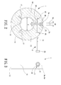
- FIGS. 1-6 A thread ring gauge of a first embodiment according to the preferred teachings of the present invention is shown in FIGS. 1-6 .
- the thread ring gauge includes a body 1, an adjusting member 2, and a plurality of gauge blocks 4a.
- the body 1 includes inner and outer peripheries 13 and 14 spaced in a radial direction.
- the inner periphery 13 defines a measuring hole and has threading to be in contact with an object to be gauged by the thread ring gauge.
- the body 10 includes a split 10 extending from the outer periphery 14 through the inner periphery 13 in the radial direction, separating the body 10 into first and second sections 11 and 12 respectively having first and second end faces 24 and 26 facing each other.
- the split 10 is formed between the first and second end faces 24 and 26.
- the split 10 has a width P between the first and second end faces 24 and 26 in the width direction.
- the first end face 24 includes a first hole 15 extending in a width direction perpendicular to the radial direction.
- the first hole 15 is interposed between and spaced from the inner and outer peripheries 13 and 14 in the radial direction.
- the second end face 26 includes a second hole 16 extending in the width direction and coaxial with the first hole 15.
- the first hole 15 is a blind screw hole
- the second hole 16 is a through-hole extending to the outer periphery 14.
- the first hole 15 can be a through-hole
- the second hole 16 can be a blind hole.
- the body 10 further includes first and second sides 27 and 28 extending between the inner and outer peripheries 13 and 14. The first and second sides 27 and 28 are spaced in an axial direction perpendicular to the radial and width directions.
- the body 10 further includes two gaps 17 extending from the inner periphery 13 towards but spaced from the outer periphery 14. Each gap 17 extends from the first side 27 through the second side 28 of the body 10 in the axial direction.
- the gaps 17 allow easy movement for reducing the width P of the slit 10 between the first and second end faces 24 and 26. However, only one or more than two gaps 17 can be formed in the body 10.
- the adjusting member 2 is extended through the second hole 16 and engaged with the first hole 15.
- the adjusting member 2 includes a threaded engaging end 21 threadedly engaged with the first hole 15 in the form of a screw hole.
- the adjusting member 2 includes an operative end 22 that can be engaged with a tool for rotating the adjusting member 2 to adjust the width P of the slit 10 between the first and second end faces 24 and 26 of the body 10.
- the first end face 24 includes a first groove 3a extending away from the second end face 26 in the width direction.
- the first groove 3a extends from the outer periphery 14 towards but spaced from the inner periphery 13 in the radial direction.
- the first groove 3a has a bottom wall 32 facing the second end face 26.
- the second end face 26 includes a second groove 3a extending away from the first end face 24 in the width direction.
- the second groove 3a extends from the outer periphery 14 towards but spaced from the inner periphery 13 in the radial direction.
- the second groove 3a has a bottom wall 34 facing the first end face 24.
- the bottom walls 32 and 34 of the first and second grooves 3a are arcuate.
- a substantially cylindrical groove is defined by the first and second grooves 3a.
- the thread ring gauge further includes first, second, and third gauge blocks 4a.
- each of the first, second, and third gauge blocks 4a is cylindrical and has circular cross sections.
- the diameter A1 of the circular cross sections of the first gauge block 4a is larger than the diameter A2 of the circular cross sections of the second gauge block 4a, which, in turn, is larger than the diameter A3 of the circular cross sections of the third gauge block 4a.
- the diameters A1-A3 can be varied according to needs. As an example, the difference between the diameters A1 and A2 can be equal to that between the diameters A2 and A3.
- the bottom walls 32 and 34 of the first and second grooves 3a have a spacing the same as the diameter A1 of the first gauge block 4a.
- the first gauge block 4a having the diameter A1 is inserted into the first and second grooves 3a.
- the threaded engaging end 21 of the adjusting member 2 is extended through the second hole 16 into the first hole 15 and then rotated to reduce the width P of the slit 10 until the first gauge block 4a abutting the bottom walls 32 and 34 of the first and second grooves 3a is securely held and no longer rotatable within the first and second grooves 3a.
- the inner periphery 13 has a normal diameter D.
- An object such as a screw or bolt to be gauged can be threadedly engaged with the threading of the inner periphery 13 of the thread ring gauge. If the object matches the threading of the inner periphery 13, the diameter of the object is equal to the normal diameter D of the inner periphery 13.
- the adjusting member 2 is rotated to increase the width P of the slit 10 so that the first gauge block 4a can be removed and replaced with the second gauge block 4a with diameter A2 smaller than diameter A1.
- the adjusting member 2 is rotated to reduce the width P of the slit 10 until the second gauge block 4a is securely held in the first and second grooves 3a.
- the inner diameter D1 of the inner periphery 13 of the body 10 is reduced back to the normal diameter D.
- the thread ring gauge can be utilized for another period of time until the threading of the inner periphery 13 becomes further worn.
- the second gauge block 4a can be replaced with the third gauge block 4a having the diameter A3 smaller than diameter A2 to extend the service life of the thread ring gauge.
- Operation of the thread ring gauge according to the preferred teachings of the present invention is easy and convenient without using wax while extending the service life of the thread ring gauge.
- Three or four replacements of the gauging blocks 4a are allowed by using more gauge blocks 4a. It can be appreciated that undesired shifting between the first and second sections 11 and 12 in the axial direction is avoided after the gauge block 4a is securely held in the first and second grooves 3a.
- FIG. 7 shows a thread ring gauge of a second embodiment according to the preferred teachings of the present invention.
- the second end face 26 does not include the second groove 3a.
- the first end face 24 includes an additional first hole 15.
- the second end face 26 includes an additional second hole 16 coaxial with the additional first hole 15.
- an additional adjusting member 2 extends through the additional second hole 16 into the additional first hole 15.
- the first groove 3a is interposed between and spaced from the first holes 15 in the axial direction.
- the gauge block 4a can be securely held in the first groove 3a and sandwiched between the bottom wall 32 of the first groove 3a and the second end face 26, avoiding undesired shifting between the first and second sections 11 and 12 in the axial direction.
- FIGS. 8 and 9 show a thread ring gauge of a third embodiment according to the preferred teachings of the present invention.
- the thread ring gauge includes a gauge block 4b including rectangular cross sections having first and second pairs of parallel sides 40 and 42.
- a spacing B2 between the second pair of parallel sides 42 is smaller than a spacing B1 between the first pair of parallel sides 40.
- the bottom walls 32 and 34 of the first and second grooves 3b have a spacing in the width direction the same as the spacing B1 between the first pair of parallel sides 40.
- the first pair of parallel sides 40 of the gauge block 4b is securely sandwiched between the bottom walls 32 and 34 of the first and second grooves 3b so that the inner periphery 13 of the body 1 has the normal diameter D.
- the gauge block 4b can be removed and then reinserted into the first and second grooves 3b with the second pair of parallel sides 42 of the gauge block 4b securely sandwiched between the bottom walls 32 and 34 of the first and second groove 3b.
- the inner diameter of the inner periphery 13 of the body 1 can, thus, be reduced back to the normal diameter D, prolonging the service life of the thread ring gauge.
- FIGS. 10 and 11 show a thread ring gauge of a fourth embodiment according to the preferred teachings of the present invention.
- the thread ring gauge includes a gauge block 4c including hexagonal cross sections having first, second, and third pairs of parallel sides 50, 52, and 54.
- a spacing C1 between the first pair of parallel sides 50 is larger than a spacing C2 between the second pair of parallel sides 52, which, in turn, is larger than a spacing C3 between the third pair of parallel sides 54.
- the bottom walls 32 and 34 of the first and second grooves 3c have a spacing in the width direction the same as the spacing C1 between the first and second parallel sides 50.
- the difference between the spacings C1 and C2 can be the same as or different from that between the spacings C2 and C3.
- the first and second grooves 3c together define a compartment having hexagonal cross sections similar to those of the gauge block 4c.
- the first pair of parallel sides 50 of the gauge block 4c is securely sandwiched between the bottom walls 32 and 34 of the first and second grooves 3c so that the inner periphery 13 of the body 1 has the normal diameter D.
- the gauge block 4c can be removed and then reinserted into the first and second grooves 3c with the second pair of parallel sides 52 of the gauge block 4c securely sandwiched between the bottom walls 32 and 34 of the first and second groove 3c.
- the inner diameter of the inner periphery 13 of the body 1 can, thus, be reduced back to the normal diameter D, prolonging the service life of the thread ring gauge. Furthermore, as the threading of the inner periphery 13 becomes further worn, the gauge block 4c can be removed and then reinserted into the first and second grooves 3c with the third pair of parallel sides 54 of the gauge block 4c securely sandwiched
- the inner diameter of the inner periphery 13 of the body 1 can, thus, be reduced back to the normal diameter D, further prolonging the service life of the thread ring gauge.
- FIG. 12 shows a threaded ring gauge of a fifth embodiment according to the preferred teachings of the present invention.
- the bottom walls 32 and 34 of the first and second grooves 3d in this embodiment are threaded and define a conic hole having increasing diameters toward the outer periphery 14.
- the threaded ring gauge includes a gauge block 4d having a threaded outer periphery threadedly engaged with the threaded bottom walls 32 and 34 of the first and second grooves 3d.
- the gauge block 4d includes increasing diameters toward the outer periphery 14 in the radial direction.
- the gauge block 4d includes a slot in an outer end face thereof and can be driven by a tool such as a screwdriver.
- the gauge block 4d can be rotated in the first and second grooves 3d and, thus, move in the radial direction. Furthermore, the adjusting member 2 can be rotated until the gauge block 4d is securely clamped between the first and second bottom walls 32 and 34. Thus, the inner diameter of the inner periphery 13 of the body 1 is reduced back to the normal diameter D.
- gauge blocks 4a having circular cross sections and the first and second grooves 3a forming a substantially cylindrical hole are preferred due to easy manufacture and processing. Furthermore, the effect of avoiding undesired shifting between the first and second sections 11 and 12 can be enhanced when the second end face 26 includes the second groove 3a.
- the thread ring gauges according to the preferred teachings of the present invention has long service lives by utilizing gauge blocks 4a, 4b, 4c, and 4d sandwiched between the grooves 3a, 3b, 3c, and 3d. Furthermore, undesired shift in the axial direction between the first and second sections 11 and 12 can be avoided when the gauge blocks 4a, 4b, 4c, and 4d have cross sections the same as or similar to those of the grooves 3a, 3b, 3c and 3d. Further, undesired shift in the axial direction between the first and second sections 11 and 12 can be further avoided by utilizing two adjusting members 2.
- grooves 3a, 3b, 3c, and 3d and the corresponding gauge blocks 4a, 4b, 4c and 4d disclosed in previous embodiments above may be further modified, as illustrated in various embodiments below.
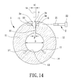
- FIG 13 shows a thread ring gauge of a sixth embodiment according to the preferred teachings of the present invention.
- the thread ring gauge in the embodiment has a similar structure as the thread ring gauge in the first embodiment ( FIG. 1 ), so it's not described herein again for brevity.
- the first end face 24 includes a first groove 3e extending away from the second end face 26 in the width direction.
- the first groove 3e extends in a greater distance from the outer periphery 14 towards the inner periphery 13 in the radial direction.
- the second end face 26 includes a second groove 3e extending away from the first end face 24 in the width direction, with the second groove 3e extending in a greater distance from the outer periphery 14 towards the inner periphery 13 in the radial direction.
- the first groove 3a has a bottom wall 32 facing the second end face 26 and the second groove 3e has a bottom wall 34 facing the first end face 24. As shown in FIG.
- the first groove 3e defines an included angle ANG1 by two planes PL1 and PL2.
- the second groove 3e defines an included angle ANG2 by two planes PL3 and PL4.
- a substantially rectangular groove 3 is defined by the first and second grooves 3e.
- the first gauge block 4e having the diameter A1 is inserted into the first and second grooves 3e.
- the threaded engaging end 21 of the adjusting member 2 is extended through the second hole 16 into the first hole 15 and then rotated to reduce the width P of the slit 10 until the first gauge block 4e abutting the bottom walls 32 and 34 of the first and second grooves 3e is securely held and no longer rotatable within the first and second grooves 3a.
- the inner periphery 13 has a normal diameter D.
- the first gauge block 4e since the first gauge block 4e is inserted under the adjusting member 2 (according to FIG. 15 ), the adjusting member 2 may be rotated more easily.
- the first gauge block 4e abutting the bottom walls 32 and 34 of the first and second grooves 3e may be securely held.
- the adjusting member 2 is rotated to increase the width P of the slit 10 so that the first gauge block 4e can be removed and replaced with the second gauge block 4e having diameter A2 smaller than the diameter A1.
- the adjusting member 2 is rotated to reduce the width P of the slit 10 until the second gauge block 4e is securely held in the first and second grooves 3e.
- the inner diameter D1 of the inner periphery 13 of the body 10 is reduced back to the normal diameter D.
- the thread ring gauge can be utilized for another period of time until the threading of the inner periphery 13 becomes further worn.
- the second gauge block 4e can be replaced with the third gauge block 4e having the diameter A3 smaller than the diameter A2 to extend the service life of the thread ring gauge.
- Operation of the thread ring gauge according to the preferred teachings of the present invention is easy and convenient without using wax while extending the service life of the thread ring gauge.
- Three or four replacements of the gauging blocks 4e are allowed by using more gauge blocks 4e. It can be appreciated that undesired shifting between the first and second sections 11 and 12 in the axial direction is avoided after the gauge block 4e is securely held in the first and second grooves 3e.
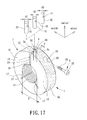
- FIG. 17 shows a thread ring gauge of a seventh embodiment according to the preferred teachings of the present invention.
- the thread ring gauge in the embodiment has a similar structure as the thread ring gauge in the sixth embodiment ( FIG. 13 ), so it's not described herein again for brevity.
- the thread ring gauge includes first, second and third gauge blocks 4f.
- each of the first, second and third gauge blocks 4f is cylindrical and has circular cross sections.
- each of the first, second and third gauge blocks 4f has a through-hole 41 that is coaxial with the first hole 15 and the second hole 16 and allows the threaded engaging end 21 of the adjusting member 2 to be passed therethrough when assembled in the first and second grooves 3e.
- each of the first, second and third gauge blocks 4f has a height H smaller than a depth DEP of the substantially rectangular groove 3 defined by the first and second grooves 3e.
- the diameter A1 of the circular cross sections of the first gauge block 4f is larger than the diameter A2 of the circular cross sections of the second gauge block 4f, which, in turn, is larger than the diameter A3 of the circular cross sections of the third gauge block 4f.
- the diameters A1-A3 can be varied according to needs. As an example, the difference between the diameters A1 and A2 can be equal to that between the diameters A2 and A3.
- the bottom walls 32 and 34 of the first and second grooves 3e have a spacing the same as the diameter A1 of the first gauge block 4a.
- the first gauge block 4f having the diameter A1 is inserted into the first and second grooves 3e.
- the threaded engaging end 21 of the adjusting member 2 is extended through the second hole 16 into the first hole 15 via the through-hole 41 and then rotated to reduce the width P of the slit 10 until the first gauge block 4f abutting the bottom walls 32 and 34 of the first and second grooves 3e is securely held and no longer rotatable within the first and second grooves 3e.
- the first gauge block 4f can be securely held in the substantially rectangular groove defined by the first and second grooves 3e, avoiding undesired shifting between the first and second sections 11 and 12 in the axial direction.
- the inner diameter of the inner periphery 13 of the body 10 may be maintained as the normal diameter D by changing the gauge blocks 4f as taught by the previous embodiments.
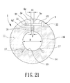
- FIG. 20 shows a thread ring gauge of an eight embodiment according to the preferred teachings of the present invention.
- the thread ring gauge in the embodiment has a similar structure as the thread ring gauge in the sixth and seventh embodiments ( FIGS. 13 and 17 ), so it's not described herein again for brevity.
- the thread ring gauge includes first, second and third sets of gauge blocks.
- Each of the first, second and third sets of gauge blocks includes two gauge blocks 4g and 4g', with both the gauge blocks 4g and 4g' being cylindrical and having the same circular cross sections.
- the gauge block 4g' is firstly inserted into the substantially rectangular compartment 3 defined by the first and second grooves 3e. Following, the threaded engaging end 21 of the adjusting member 2 is extended through the second hole 16 into the first hole 15. Before the threaded engaging end 21 of the adjusting member 2 is screwed to the first hole 15, the gauge block 4g is subsequently inserted into the substantially rectangular compartment 3.
- the threaded engaging end 21 of the adjusting member 2 is screwed to the first hole 15 so that the gauge blocks 4g' and 4g are securely held within the first and second grooves 3e.
- the threaded engaging end 21 of the adjusting member 2 is screwed to the first hole 15 so that the gauge blocks 4g' and 4g are securely held within the first and second grooves 3e.
Abstract
Description
- The present invention relates to a thread ring gauge and, more particularly, to a thread ring gauge including a measuring hole having a reducible inner diameter.
- Conventional thread ring gauges include a measuring hole having inner threading and an inner diameter for measuring sizes of screws or bolts. In one type of thread ring gauges, the inner diameter of the measuring hole is fixed such that the thread ring gauges can not be utilized after the inner threading is worn out and, thus, causes a change in the inner diameter. In another type of thread ring gauges, the inner diameter of the measuring hole is adjustable. In an example disclosed in
U.S. Patent No. 1,447,448 , the female gauge includes a gauge body having a split formed between two relatively adjustable end sections. The female gauge includes an interior gauge surface adapted to contact with parts to be gauged. Two aligned screws are mounted in aligned apertures in the end sections. One or both of the screws can be rotated to adjust the split. - In use, the inner diameter of the interior gauge surface of the female gauge is calibrated to be equal to a normal size, and the split is filled with wax to indicate that the female gauge is of the normal size. The wax cracks as the inner threading becomes worn. In this case, the wax cracks, and the female gauge must be recalibrated to the normal size. However, the wax could crack due to other reasons including, but not limited to, impact to the female gauge or a change in temperature. Recalibration is troublesome, for the precision tolerance is only about 8µ.
- Thus, a need exists for a thread ring gauge that can be easily calibrated while having a longer service life to reduce the costs.
- The primary objective of the present invention is to provide a thread ring gauge having an inner diameter that can be easily calibrated.
- Another objective of the present invention is to provide a thread ring gauge having an inner diameter that can be easily fixed to a normal size.
- A further objective of the present invention is to provide a thread ring gauge with a longer service life to reduce the costs.
- Still another objective of the present invention is to provide a thread ring gauge that can avoid undesired shift between two ends in an axial direction of the thread ring gauge.
- The present invention solves this need and other problems and fulfills the above objectives in the field of thread ring gauges by providing, in a preferred aspect, a thread ring gauge including a body having inner and outer peripheries spaced in a radial direction. The inner periphery has threading. The body includes a split extending from the outer periphery through the inner periphery in the radial direction, separating the body into first and second sections respectively having first and second end faces facing each other. The split is formed between the first and second end faces. The first end face includes a first hole extending in a width direction perpendicular to the radial direction. The first hole is interposed between and spaced from the inner and outer peripheries in the radial direction. The second end face includes a second hole extending in the width direction and coaxial with the first hole. At least one of the first and second holes extends to the outer periphery. The first end face includes a first groove extending away from the second end face in the width direction. The first groove extends from the outer periphery towards but spaced from the inner periphery in the radial direction. The first groove has a bottom wall facing the second end face. A first adjusting member is received in the first and second holes. The first adjusting member is movable to adjust a width of the slit between the first and second end faces in the width direction. A first gauge block is received in the first groove and abuts the bottom wall of the first groove and the second end face.
- Preferably, the second end face includes a second groove extending away from the first end face in the width direction. The second groove extends from the outer periphery towards but spaced from the inner periphery in the radial direction. The second groove has a bottom wall facing the first end face. The first gauge block is received in the first and second grooves and abutting the bottom walls of the first and second grooves.
- In a preferred embodiment, the bottom walls of the first and second grooves are arcuate, and the first gauge block is cylindrical and has circular cross sections. A second gauge block has circular cross sections with a diameter smaller than that of the circular cross sections of the first gauge block. The first gauge block is replaced with the second gauge block as the threading of the inner periphery becomes worn, and the second gauge block abuts the bottom walls of the first and second grooves.
- In another preferred embodiment, the bottom walls of the first and second grooves define a conic hole having increasing diameters toward the outer periphery. The first gauge block includes an outer periphery engaged with the bottom walls of the first and second grooves. The first gauge block includes increasing diameters toward the outer periphery in the radial direction. The first gauge block is rotatable to move in the first and second grooves in the radial direction.
- In a further preferred embodiment, the first gauge block has polygonal cross sections having first and second pairs of parallel sides. A first spacing between the first pair of parallel sides is larger than a second spacing between the second pair of parallel sides. The bottom walls of the first and second grooves have a spacing in the width direction the same as the first spacing between the first pair of parallel sides.
- In still another embodiment, the first gauge block further includes a third pair of parallel sides. The third pair of parallel sides has a spacing smaller than the first spacing between the first pair of parallel sides and different from the second spacing between the second pair of parallel sides.
- In a preferred embodiment, the first end face further includes a third hole extending in the width direction. The third hole is interposed between and spaced from the inner and outer peripheries in the radial direction. The second end face includes a fourth hole extending in the width direction and coaxial with the third hole. At least one of the third and fourth holes extends to the outer periphery. A second adjusting member is received in the third and fourth holes and movable to adjust the width of the slit in the width direction.
- The present invention will become clearer in light of the following detailed description of illustrative embodiments of this invention described in connection with the drawings.
- The illustrative embodiments may best be described by reference to the accompanying drawings where:
-
FIG. 1 shows an exploded, perspective view of a thread ring gauge of a first embodiment according to the preferred teachings of the present invention. -
FIG. 2 shows an exploded, cross sectional view of the thread ring gauge ofFIG. 1 . -
FIG. 3 shows a right side view of the thread ring gauge ofFIG. 2 . -
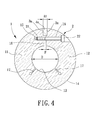
FIG. 4 shows a cross sectional view of the thread ring gauge ofFIG. 1 in use. -
FIG. 5 is a cross sectional view similar toFIG. 4 , illustrating wear of the thread ring gauge ofFIG. 1 . -
FIG. 6 shows a cross sectional view of the thread ring gauge ofFIG. 1 using a gauge block of a smaller size. -
FIG. 7 shows an exploded, perspective view of a thread ring gauge of a second embodiment according to the preferred teachings of the present invention. -
FIG. 8 shows an exploded, perspective view of a thread ring gauge of a third embodiment according to the preferred teachings of the present invention. -
FIG. 9 shows a cross sectional view of a gauge block ofFIG. 8 . -
FIG. 10 shows an exploded, perspective view of a thread ring gauge of a fourth embodiment according to the preferred teachings of the present invention. -
FIG. 11 shows a cross sectional view of a gauge block ofFIG. 10 . -
FIG. 12 shows an exploded, perspective view of a thread ring gauge of a fifth embodiment according to the preferred teachings of the present invention. -
FIG. 13 shows an exploded, perspective view of a thread ring gauge of a sixth embodiment according to the preferred teachings of the present invention. -
FIG. 14 shows an exploded, cross sectional view of the thread ring gauge ofFIG. 13 . -
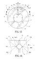
FIG. 15 shows a cross sectional view of the thread ring gauge ofFIG. 13 in use. -
FIG. 16 shows two included angles defined on the thread ring gauge ofFIG. 13 . -
FIG. 17 shows an exploded, perspective view of a thread ring gauge of a seventh embodiment according to the preferred teachings of the present invention. -
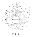
FIG. 18 shows an exploded, cross sectional view of the thread ring gauge ofFIG. 17 . -
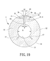
FIG. 19 shows a cross sectional view of the thread ring gauge ofFIG. 17 in use. -
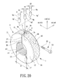
FIG. 20 shows an exploded, perspective view of a thread ring gauge of an eight embodiment according to the preferred teachings of the present invention. -
FIG. 21 shows a cross sectional view of the thread ring gauge ofFIG. 20 in use. - All figures are drawn for ease of explanation of the basic teachings of the present invention only; the extensions of the figures with respect to number, position, relationship, and dimensions of the parts to form the preferred embodiments will be explained or will be within the skill of the art after the following teachings of the present invention have been read and understood. Further, the exact dimensions and dimensional proportions to conform to specific force, weight, strength, and similar requirements will likewise be within the skill of the art after the following teachings of the present invention have been read and understood.
- Where used in the various figures of the drawings, the same numerals designate the same or similar parts. Furthermore, when the terms "first", "second", "third", "fourth", "inner", "outer", "end", "portion", "section", "axial", "radial", "spacing", "width", and similar terms are used herein, it should be understood that these terms have reference only to the structure shown in the drawings as it would appear to a person viewing the drawings and are utilized only to facilitate describing the invention.
- A thread ring gauge of a first embodiment according to the preferred teachings of the present invention is shown in
FIGS. 1-6 . The thread ring gauge includes abody 1, an adjustingmember 2, and a plurality ofgauge blocks 4a. Thebody 1 includes inner andouter peripheries inner periphery 13 defines a measuring hole and has threading to be in contact with an object to be gauged by the thread ring gauge. Thebody 10 includes asplit 10 extending from theouter periphery 14 through theinner periphery 13 in the radial direction, separating thebody 10 into first andsecond sections split 10 is formed between the first and second end faces 24 and 26. Thus, thesplit 10 has a width P between the first and second end faces 24 and 26 in the width direction. Thefirst end face 24 includes afirst hole 15 extending in a width direction perpendicular to the radial direction. Thefirst hole 15 is interposed between and spaced from the inner andouter peripheries second end face 26 includes asecond hole 16 extending in the width direction and coaxial with thefirst hole 15. Thefirst hole 15 is a blind screw hole, and thesecond hole 16 is a through-hole extending to theouter periphery 14. However, thefirst hole 15 can be a through-hole, and thesecond hole 16 can be a blind hole. Thebody 10 further includes first andsecond sides outer peripheries second sides body 10 further includes twogaps 17 extending from theinner periphery 13 towards but spaced from theouter periphery 14. Eachgap 17 extends from thefirst side 27 through thesecond side 28 of thebody 10 in the axial direction. Thegaps 17 allow easy movement for reducing the width P of theslit 10 between the first and second end faces 24 and 26. However, only one or more than twogaps 17 can be formed in thebody 10. - With reference to
FIGS. 1-3 , the adjustingmember 2 is extended through thesecond hole 16 and engaged with thefirst hole 15. Specifically, the adjustingmember 2 includes a threadedengaging end 21 threadedly engaged with thefirst hole 15 in the form of a screw hole. Furthermore, the adjustingmember 2 includes anoperative end 22 that can be engaged with a tool for rotating the adjustingmember 2 to adjust the width P of theslit 10 between the first and second end faces 24 and 26 of thebody 10. - With reference to
FIGS. 1-3 , thefirst end face 24 includes afirst groove 3a extending away from thesecond end face 26 in the width direction. Thefirst groove 3a extends from theouter periphery 14 towards but spaced from theinner periphery 13 in the radial direction. Thefirst groove 3a has abottom wall 32 facing thesecond end face 26. Thesecond end face 26 includes asecond groove 3a extending away from thefirst end face 24 in the width direction. Thesecond groove 3a extends from theouter periphery 14 towards but spaced from theinner periphery 13 in the radial direction. Thesecond groove 3a has abottom wall 34 facing thefirst end face 24. Thebottom walls second grooves 3a are arcuate. A substantially cylindrical groove is defined by the first andsecond grooves 3a. - With reference to
FIGS. 3-4 , the thread ring gauge further includes first, second, andthird gauge blocks 4a. Specifically, each of the first, second, andthird gauge blocks 4a is cylindrical and has circular cross sections. Furthermore, the diameter A1 of the circular cross sections of thefirst gauge block 4a is larger than the diameter A2 of the circular cross sections of thesecond gauge block 4a, which, in turn, is larger than the diameter A3 of the circular cross sections of thethird gauge block 4a. The diameters A1-A3 can be varied according to needs. As an example, the difference between the diameters A1 and A2 can be equal to that between the diameters A2 and A3. Thebottom walls second grooves 3a have a spacing the same as the diameter A1 of thefirst gauge block 4a. - In use, the
first gauge block 4a having the diameter A1 is inserted into the first andsecond grooves 3a. The threadedengaging end 21 of the adjustingmember 2 is extended through thesecond hole 16 into thefirst hole 15 and then rotated to reduce the width P of theslit 10 until thefirst gauge block 4a abutting thebottom walls second grooves 3a is securely held and no longer rotatable within the first andsecond grooves 3a. At this time, theinner periphery 13 has a normal diameter D. An object such as a screw or bolt to be gauged can be threadedly engaged with the threading of theinner periphery 13 of the thread ring gauge. If the object matches the threading of theinner periphery 13, the diameter of the object is equal to the normal diameter D of theinner periphery 13. - With reference to
FIG. 5 , as the threading of theinner periphery 13 becomes worn after the thread ring gauge has been utilized for a period of time such that the inner diameter of theinner periphery 13 becomes larger then the normal diameter D (see diameter D1), the adjustingmember 2 is rotated to increase the width P of theslit 10 so that thefirst gauge block 4a can be removed and replaced with thesecond gauge block 4a with diameter A2 smaller than diameter A1. The adjustingmember 2 is rotated to reduce the width P of theslit 10 until thesecond gauge block 4a is securely held in the first andsecond grooves 3a. Thus, as shown inFIG. 6 , the inner diameter D1 of theinner periphery 13 of thebody 10 is reduced back to the normal diameter D. The thread ring gauge can be utilized for another period of time until the threading of theinner periphery 13 becomes further worn. However, thesecond gauge block 4a can be replaced with thethird gauge block 4a having the diameter A3 smaller than diameter A2 to extend the service life of the thread ring gauge. Operation of the thread ring gauge according to the preferred teachings of the present invention is easy and convenient without using wax while extending the service life of the thread ring gauge. Three or four replacements of the gaugingblocks 4a are allowed by usingmore gauge blocks 4a. It can be appreciated that undesired shifting between the first andsecond sections gauge block 4a is securely held in the first andsecond grooves 3a. -
FIG. 7 shows a thread ring gauge of a second embodiment according to the preferred teachings of the present invention. In this embodiment, thesecond end face 26 does not include thesecond groove 3a. Furthermore, thefirst end face 24 includes an additionalfirst hole 15. Further, thesecond end face 26 includes an additionalsecond hole 16 coaxial with the additionalfirst hole 15. Further, anadditional adjusting member 2 extends through the additionalsecond hole 16 into the additionalfirst hole 15. Thefirst groove 3a is interposed between and spaced from thefirst holes 15 in the axial direction. Thus, thegauge block 4a can be securely held in thefirst groove 3a and sandwiched between thebottom wall 32 of thefirst groove 3a and thesecond end face 26, avoiding undesired shifting between the first andsecond sections -
FIGS. 8 and 9 show a thread ring gauge of a third embodiment according to the preferred teachings of the present invention. In this embodiment, the thread ring gauge includes agauge block 4b including rectangular cross sections having first and second pairs ofparallel sides parallel sides 42 is smaller than a spacing B1 between the first pair ofparallel sides 40. Thebottom walls second grooves 3b have a spacing in the width direction the same as the spacing B1 between the first pair ofparallel sides 40. When in use, the first pair ofparallel sides 40 of thegauge block 4b is securely sandwiched between thebottom walls second grooves 3b so that theinner periphery 13 of thebody 1 has the normal diameter D. As the threading of theinner periphery 13 becomes worn, thegauge block 4b can be removed and then reinserted into the first andsecond grooves 3b with the second pair ofparallel sides 42 of thegauge block 4b securely sandwiched between thebottom walls second groove 3b. The inner diameter of theinner periphery 13 of thebody 1 can, thus, be reduced back to the normal diameter D, prolonging the service life of the thread ring gauge. -
FIGS. 10 and 11 show a thread ring gauge of a fourth embodiment according to the preferred teachings of the present invention. In this embodiment, the thread ring gauge includes agauge block 4c including hexagonal cross sections having first, second, and third pairs ofparallel sides parallel sides 50 is larger than a spacing C2 between the second pair ofparallel sides 52, which, in turn, is larger than a spacing C3 between the third pair ofparallel sides 54. Thebottom walls second grooves 3c have a spacing in the width direction the same as the spacing C1 between the first and second parallel sides 50. The difference between the spacings C1 and C2 can be the same as or different from that between the spacings C2 and C3. The first andsecond grooves 3c together define a compartment having hexagonal cross sections similar to those of thegauge block 4c. When in use, the first pair ofparallel sides 50 of thegauge block 4c is securely sandwiched between thebottom walls second grooves 3c so that theinner periphery 13 of thebody 1 has the normal diameter D. As the threading of theinner periphery 13 becomes worn, thegauge block 4c can be removed and then reinserted into the first andsecond grooves 3c with the second pair ofparallel sides 52 of thegauge block 4c securely sandwiched between thebottom walls second groove 3c. The inner diameter of theinner periphery 13 of thebody 1 can, thus, be reduced back to the normal diameter D, prolonging the service life of the thread ring gauge. Furthermore, as the threading of theinner periphery 13 becomes further worn, thegauge block 4c can be removed and then reinserted into the first andsecond grooves 3c with the third pair ofparallel sides 54 of thegauge block 4c securely sandwiched - between the
bottom walls second groove 3c. The inner diameter of theinner periphery 13 of thebody 1 can, thus, be reduced back to the normal diameter D, further prolonging the service life of the thread ring gauge. -
FIG. 12 shows a threaded ring gauge of a fifth embodiment according to the preferred teachings of the present invention. Specifically, thebottom walls second grooves 3d in this embodiment are threaded and define a conic hole having increasing diameters toward theouter periphery 14. The threaded ring gauge includes agauge block 4d having a threaded outer periphery threadedly engaged with the threadedbottom walls second grooves 3d. Thegauge block 4d includes increasing diameters toward theouter periphery 14 in the radial direction. Thegauge block 4d includes a slot in an outer end face thereof and can be driven by a tool such as a screwdriver. Specifically, as the threading of theinner periphery 13 becomes worn, thegauge block 4d can be rotated in the first andsecond grooves 3d and, thus, move in the radial direction. Furthermore, the adjustingmember 2 can be rotated until thegauge block 4d is securely clamped between the first and secondbottom walls inner periphery 13 of thebody 1 is reduced back to the normal diameter D. - It can be appreciated that the
gauge blocks 4a having circular cross sections and the first andsecond grooves 3a forming a substantially cylindrical hole are preferred due to easy manufacture and processing. Furthermore, the effect of avoiding undesired shifting between the first andsecond sections second end face 26 includes thesecond groove 3a. - The thread ring gauges according to the preferred teachings of the present invention has long service lives by utilizing
gauge blocks grooves second sections gauge blocks grooves second sections members 2. - The
grooves corresponding gauge blocks -
FIG 13 shows a thread ring gauge of a sixth embodiment according to the preferred teachings of the present invention. The thread ring gauge in the embodiment has a similar structure as the thread ring gauge in the first embodiment (FIG. 1 ), so it's not described herein again for brevity. - With reference to
FIGS. 13 to 16 , thefirst end face 24 includes afirst groove 3e extending away from thesecond end face 26 in the width direction. In comparison with the first embodiment, thefirst groove 3e extends in a greater distance from theouter periphery 14 towards theinner periphery 13 in the radial direction. Similarly, thesecond end face 26 includes asecond groove 3e extending away from thefirst end face 24 in the width direction, with thesecond groove 3e extending in a greater distance from theouter periphery 14 towards theinner periphery 13 in the radial direction. Furthermore, thefirst groove 3a has abottom wall 32 facing thesecond end face 26 and thesecond groove 3e has abottom wall 34 facing thefirst end face 24. As shown inFIG. 16 , thefirst groove 3e defines an included angle ANG1 by two planes PL1 and PL2. Similarly, thesecond groove 3e defines an included angle ANG2 by two planes PL3 and PL4. A substantiallyrectangular groove 3 is defined by the first andsecond grooves 3e. - In use, the
first gauge block 4e having the diameter A1 is inserted into the first andsecond grooves 3e. The threadedengaging end 21 of the adjustingmember 2 is extended through thesecond hole 16 into thefirst hole 15 and then rotated to reduce the width P of theslit 10 until thefirst gauge block 4e abutting thebottom walls second grooves 3e is securely held and no longer rotatable within the first andsecond grooves 3a. At this time, theinner periphery 13 has a normal diameter D. In the embodiment, since thefirst gauge block 4e is inserted under the adjusting member 2 (according toFIG. 15 ), the adjustingmember 2 may be rotated more easily. In addition, due to the substantiallyrectangular compartment 3 defined by the first andsecond grooves 3e, thefirst gauge block 4e abutting thebottom walls second grooves 3e may be securely held. - As the threading of the
inner periphery 13 becomes worn after the thread ring gauge has been utilized for a period of time such that the inner diameter of theinner periphery 13 becomes larger then the normal diameter D (see diameter D1), the adjustingmember 2 is rotated to increase the width P of theslit 10 so that thefirst gauge block 4e can be removed and replaced with thesecond gauge block 4e having diameter A2 smaller than the diameter A1. The adjustingmember 2 is rotated to reduce the width P of theslit 10 until thesecond gauge block 4e is securely held in the first andsecond grooves 3e. Thus, the inner diameter D1 of theinner periphery 13 of thebody 10 is reduced back to the normal diameter D. The thread ring gauge can be utilized for another period of time until the threading of theinner periphery 13 becomes further worn. However, thesecond gauge block 4e can be replaced with thethird gauge block 4e having the diameter A3 smaller than the diameter A2 to extend the service life of the thread ring gauge. Operation of the thread ring gauge according to the preferred teachings of the present invention is easy and convenient without using wax while extending the service life of the thread ring gauge. Three or four replacements of the gaugingblocks 4e are allowed by usingmore gauge blocks 4e. It can be appreciated that undesired shifting between the first andsecond sections gauge block 4e is securely held in the first andsecond grooves 3e. -
FIG. 17 shows a thread ring gauge of a seventh embodiment according to the preferred teachings of the present invention. The thread ring gauge in the embodiment has a similar structure as the thread ring gauge in the sixth embodiment (FIG. 13 ), so it's not described herein again for brevity. - With reference to
FIGS. 17 to 19 , the thread ring gauge includes first, second andthird gauge blocks 4f. Specifically, each of the first, second andthird gauge blocks 4f is cylindrical and has circular cross sections. Furthermore, each of the first, second andthird gauge blocks 4f has a through-hole 41 that is coaxial with thefirst hole 15 and thesecond hole 16 and allows the threadedengaging end 21 of the adjustingmember 2 to be passed therethrough when assembled in the first andsecond grooves 3e. Furthermore, each of the first, second andthird gauge blocks 4f has a height H smaller than a depth DEP of the substantiallyrectangular groove 3 defined by the first andsecond grooves 3e. Similar to thegauge blocks first gauge block 4f is larger than the diameter A2 of the circular cross sections of thesecond gauge block 4f, which, in turn, is larger than the diameter A3 of the circular cross sections of thethird gauge block 4f. The diameters A1-A3 can be varied according to needs. As an example, the difference between the diameters A1 and A2 can be equal to that between the diameters A2 and A3. Thebottom walls second grooves 3e have a spacing the same as the diameter A1 of thefirst gauge block 4a. - In use, the
first gauge block 4f having the diameter A1 is inserted into the first andsecond grooves 3e. The threadedengaging end 21 of the adjustingmember 2 is extended through thesecond hole 16 into thefirst hole 15 via the through-hole 41 and then rotated to reduce the width P of theslit 10 until thefirst gauge block 4f abutting thebottom walls second grooves 3e is securely held and no longer rotatable within the first andsecond grooves 3e. Thus, thefirst gauge block 4f can be securely held in the substantially rectangular groove defined by the first andsecond grooves 3e, avoiding undesired shifting between the first andsecond sections - As the threading of the
inner periphery 13 becomes worn, one skilled in the art would appreciate that the inner diameter of theinner periphery 13 of thebody 10 may be maintained as the normal diameter D by changing thegauge blocks 4f as taught by the previous embodiments. -
FIG. 20 shows a thread ring gauge of an eight embodiment according to the preferred teachings of the present invention. The thread ring gauge in the embodiment has a similar structure as the thread ring gauge in the sixth and seventh embodiments (FIGS. 13 and17 ), so it's not described herein again for brevity. - With reference to
FIGS. 19 and20 , the thread ring gauge includes first, second and third sets of gauge blocks. Each of the first, second and third sets of gauge blocks includes twogauge blocks gauge blocks FIG. 21 , thegauge block 4g' is firstly inserted into the substantiallyrectangular compartment 3 defined by the first andsecond grooves 3e. Following, the threadedengaging end 21 of the adjustingmember 2 is extended through thesecond hole 16 into thefirst hole 15. Before the threadedengaging end 21 of the adjustingmember 2 is screwed to thefirst hole 15, thegauge block 4g is subsequently inserted into the substantiallyrectangular compartment 3. Finally, the threadedengaging end 21 of the adjustingmember 2 is screwed to thefirst hole 15 so that thegauge blocks 4g' and 4g are securely held within the first andsecond grooves 3e. Thus, undesired shifting between the first andsecond sections gauge block 4g', may be avoided. - Thus since the invention disclosed herein may be embodied in other specific forms without departing from the spirit or general characteristics thereof, some of which forms have been indicated, the embodiments described herein are to be considered in all respects illustrative and not restrictive. The scope of the invention is to be indicated by the appended claims, rather than by the foregoing description, and all changes which come within the meaning and range of equivalency of the claims are intended to be embraced therein.
Claims (13)
- A thread ring gauge comprising:a body (1) including inner and outer peripheries (13, 14) spaced in a radial direction, with the inner periphery (13) having threading, with the body (1) including a split (10) extending from the outer periphery (14) through the inner periphery (13) in the radial direction, separating the body (1) into first and second sections (11, 12) respectively having first and second end faces (24, 26) facing each other, with the split (10) formed between the first and second end faces (24, 26), with the first end face (24, 26) including a first hole (15) extending in a width direction perpendicular to the radial direction, with the first hole (15) interposed between and spaced from the inner and outer peripheries (13, 14) in the radial direction, with the second end face (26) including a second hole (16) extending in the width direction and coaxial with the first hole (15), with at least one of the first and second holes (15, 16) extending to the outer periphery (14), with the first end face (24) including a first groove (3a, 3b, 3c, 3d, 3e) extending away from the second end face (26) in the width direction, with the first groove (3a, 3b, 3c, 3d, 3e) extending from the outer periphery (14) towards but spaced from the inner periphery (13) in the radial direction, with the first groove (3a, 3b, 3c, 3d, 3e) having a bottom wall (32) facing the second end face (26);a first adjusting member (2) received in the first and second holes (15, 16), with the first adjusting member (2) being movable to adjust a width (P) of the slit (10) between the first and second end faces (24, 26) in the width direction; anda first gauge block (4a, 4b, 4c, 4d, 4e, 4f) received in the first groove (3a, 3b, 3c, 3d, 3e) and abutting the bottom wall (32) of the first groove (3a, 3b, 3c, 3d, 3e) and the second end face (26).
- The thread ring gauge as claimed in claim 1, with the second end face (26) including a second groove (3a, 3b, 3c, 3d, 3e) extending away from the first end face (24) in the width direction, with the second groove (3a, 3b, 3c, 3d, 3e) extending from the outer periphery (14) towards but spaced from the inner periphery (13) in the radial direction, with the second groove (3a, 3b, 3c, 3d, 3e) having a bottom wall (34) facing the first end face (24), and with the first gauge block (4a, 4b, 4c, 4d, 4e, 4f) received in the first and second grooves (3a, 3b, 3c, 3d, 3e) and abutting the bottom walls (32, 34) of the first and second grooves (3a, 3b, 3c, 3d, 3e).
- The thread ring gauge as claimed in claim 2, with the bottom walls (32, 34) of the first and second grooves (3a) being arcuate, and with the first gauge block (4a) being cylindrical and having circular cross sections.
- The thread ring gauge as claimed in claim 3, further comprising a second gauge block (4a) having circular cross sections with a diameter (A2) smaller than that (A1) of the circular cross sections of the first gauge block (4a), with the first gauge block (4a) being replaced with the second gauge block (4a) when the threading of the inner periphery (13) becomes worn, and with the second gauge block (4a) abutting the bottom walls (32, 34) of the first and second grooves (3a).
- the thread ring gauge as claimed in claim 2, with the bottom walls (32, 34) of the first and second grooves (3d) being threaded and defining a conic hole having increasing diameters toward the outer periphery (14), with the first gauge block (4d) including a threaded outer periphery threadedly engaged with the bottom walls (32, 34) of the first and second grooves (3d), with the first gauge block (4d) including increasing diameters toward the outer periphery (14) in the radial direction, and with the first gauge block (4d) being rotatable to move in the first and second grooves (3d) in the radial direction.
- The thread ring gauge as claimed in claim 2, with the first gauge block (4c) having polygonal cross sections having first and second pairs of parallel sides, with a first spacing (C1) between the first pair of parallel sides being larger than a second spacing (C2) between the second pair of parallel sides, with the bottom walls (32, 34) of the first and second grooves (3c) having a third spacing (C3) in the width direction the same as the first spacing (C1) between the first pair of parallel sides.
- The thread ring gauge as claimed in claim 1, with the first hole (15) being a screw hole, with the first adjusting member (2) including a first, threaded end (21) threadedly engaged with the screw hole, and with the first adjusting member (2) further including a second end (22) adapted to be driven to adjust the width (P) of the slit (10).
- The thread ring gauge as claimed in claim 1, with the first end face (24) further including a third hole (15) extending in the width direction, with the third hole (15) interposed between and spaced from the inner and outer peripheries (13, 14) in the radial direction, with the second end face (26) including a fourth hole (16) extending in the width direction and coaxial with the third hole (15), with at least one of the third and fourth holes (15, 16) extending to the outer periphery (14), with the thread ring gauge further comprising: a second adjusting member (2) received in the third and fourth holes (15, 16), with the second adjusting member (2) being movable to adjust the width (P) of the slit (10) in the width direction.
- The thread ring gauge as claimed in claim 8, with the third hole (15) being a screw hole, with the second adjusting member (2) including a first, threaded end (21) threadedly engaged with the screw hole, and with the second adjusting member (2) further including a second end (22) adapted to be driven to adjust the width (P) of the slit (10).
- The thread ring gauge as claimed in claim 1, with the body (1) further including first and second sides (27, 28) extending between the inner and outer peripheries (13, 14), with the first and second sides (27, 28) spaced in an axial direction perpendicular to the radial and width directions, with the body (1) further including at least one gap (17) extending from the inner periphery (13) towards but spaced from the outer periphery (14), and with said at least one gap (17) extending from the first side (27) through the second side (28) of the body (1) in the axial direction.
- The thread ring gauge as claimed in claim 1, with each of the first and second grooves (3e) defining an included angle (ANG1, ANG2) by two planes (PL1, PL2 or PL3, PL4).
- The thread ring gauge as claimed in claim 1, with the first and second grooves defining a substantially rectangular compartment (3), with the first gauge block (4f) having a height (H) smaller than a depth (DEP) of the substantially rectangular compartment (3).
- The thread ring gauge as claimed in claim 1, with the first gauge block (4f) having a through-hole (41) that is coaxial with the first and second holes (15, 16) and allowing the first adjusting member (2) to be passed therethrough.
Applications Claiming Priority (2)
| Application Number | Priority Date | Filing Date | Title |
|---|---|---|---|
| TW98113222A TWI386623B (en) | 2009-04-21 | 2009-04-21 | Thread ring gage |
| TW98213723U TWM370068U (en) | 2009-07-27 | 2009-07-27 | Thread ring gage |
Publications (2)
| Publication Number | Publication Date |
|---|---|
| EP2244051A1 true EP2244051A1 (en) | 2010-10-27 |
| EP2244051B1 EP2244051B1 (en) | 2011-07-06 |
Family
ID=42352043
Family Applications (1)
| Application Number | Title | Priority Date | Filing Date |
|---|---|---|---|
| EP10155637A Not-in-force EP2244051B1 (en) | 2009-04-21 | 2010-03-05 | Thread ring gauge |
Country Status (3)
| Country | Link |
|---|---|
| EP (1) | EP2244051B1 (en) |
| KR (1) | KR101214335B1 (en) |
| AT (1) | ATE515677T1 (en) |
Cited By (6)
| Publication number | Priority date | Publication date | Assignee | Title |
|---|---|---|---|---|
| CN103398692A (en) * | 2013-07-26 | 2013-11-20 | 苏州信能精密机械有限公司 | Mechanism for measuring bore diameter of part |
| CN103486944A (en) * | 2013-10-09 | 2014-01-01 | 河南柴油机重工有限责任公司 | Method and device for high-precision shaft key groove depth error measurement |
| CN104416329A (en) * | 2013-08-23 | 2015-03-18 | 重庆长安工业(集团)有限责任公司 | Method for processing small-size spline ring gage |
| CN106017245A (en) * | 2016-05-31 | 2016-10-12 | 芜湖卓越空调零部件有限公司 | High precision durable exhaust pipe ring gage |
| CN109443136A (en) * | 2018-12-19 | 2019-03-08 | 昆山鑫轮超硬磨具有限公司 | External screw thread detection machine |
| CN116294888A (en) * | 2023-04-11 | 2023-06-23 | 北京力威尔航空精密机械有限公司 | Screw plug gauge capable of displaying service life and method for calibrating internal screw hole |
Citations (2)
| Publication number | Priority date | Publication date | Assignee | Title |
|---|---|---|---|---|
| US1447448A (en) | 1919-07-24 | 1923-03-06 | Pratt & Whitney Co | Female gauge |
| US2789360A (en) * | 1953-11-18 | 1957-04-23 | Pipe Machinery Company | Method and means for checking and setting gages |
Family Cites Families (3)
| Publication number | Priority date | Publication date | Assignee | Title |
|---|---|---|---|---|
| JP3837503B2 (en) | 2002-05-09 | 2006-10-25 | 独立行政法人産業技術総合研究所 | 3D coordinate evaluation gauge |
| JP3949593B2 (en) | 2003-02-10 | 2007-07-25 | 日本山村硝子株式会社 | Inspection device for inner and outer diameter of bottle mouth |
| JP4623262B2 (en) | 2004-02-26 | 2011-02-02 | 豊和工業株式会社 | Tapering gauge |
-
2010
- 2010-03-05 AT AT10155637T patent/ATE515677T1/en not_active IP Right Cessation
- 2010-03-05 EP EP10155637A patent/EP2244051B1/en not_active Not-in-force
- 2010-04-09 KR KR1020100032794A patent/KR101214335B1/en not_active IP Right Cessation
Patent Citations (2)
| Publication number | Priority date | Publication date | Assignee | Title |
|---|---|---|---|---|
| US1447448A (en) | 1919-07-24 | 1923-03-06 | Pratt & Whitney Co | Female gauge |
| US2789360A (en) * | 1953-11-18 | 1957-04-23 | Pipe Machinery Company | Method and means for checking and setting gages |
Cited By (8)
| Publication number | Priority date | Publication date | Assignee | Title |
|---|---|---|---|---|
| CN103398692A (en) * | 2013-07-26 | 2013-11-20 | 苏州信能精密机械有限公司 | Mechanism for measuring bore diameter of part |
| CN103398692B (en) * | 2013-07-26 | 2016-01-20 | 苏州信能精密机械有限公司 | The measuring mechanism of inner bore of part diameter |
| CN104416329A (en) * | 2013-08-23 | 2015-03-18 | 重庆长安工业(集团)有限责任公司 | Method for processing small-size spline ring gage |
| CN103486944A (en) * | 2013-10-09 | 2014-01-01 | 河南柴油机重工有限责任公司 | Method and device for high-precision shaft key groove depth error measurement |
| CN106017245A (en) * | 2016-05-31 | 2016-10-12 | 芜湖卓越空调零部件有限公司 | High precision durable exhaust pipe ring gage |
| CN109443136A (en) * | 2018-12-19 | 2019-03-08 | 昆山鑫轮超硬磨具有限公司 | External screw thread detection machine |
| CN116294888A (en) * | 2023-04-11 | 2023-06-23 | 北京力威尔航空精密机械有限公司 | Screw plug gauge capable of displaying service life and method for calibrating internal screw hole |
| CN116294888B (en) * | 2023-04-11 | 2023-12-08 | 北京力威尔航空精密机械有限公司 | Screw plug gauge capable of displaying service life and method for calibrating internal screw hole |
Also Published As
| Publication number | Publication date |
|---|---|
| KR101214335B1 (en) | 2012-12-20 |
| KR20100116116A (en) | 2010-10-29 |
| EP2244051B1 (en) | 2011-07-06 |
| ATE515677T1 (en) | 2011-07-15 |
Similar Documents
| Publication | Publication Date | Title |
|---|---|---|
| US7918031B2 (en) | Thread ring gauge | |
| EP2244051A1 (en) | Thread ring gauge | |
| US8695432B2 (en) | Screw with stress sensing device | |
| US9475131B2 (en) | Milling cutter with stress reliefs | |
| RU2608252C2 (en) | Cutting tool, containing seat element for stress reduction | |
| US20110318121A1 (en) | Cutting tip comprising a grooved shank, and cutting tool comprising such a cutting tip | |
| US10208775B2 (en) | Methods of frictional coupling | |
| CN106604795B (en) | Cutting element retainer with vibration damping balance weight assembly | |
| US20170197258A1 (en) | Rotary cutting tool with internal balancing feature | |
| CN105364227B (en) | Thread shaping tap | |
| JP3201837U (en) | Building blocks | |
| EP3936249A1 (en) | Measuring roller for determining a property of a strip-like product guided over the measuring roller | |
| KR20160037232A (en) | Rod-shaped force transducer with simplified adjustment | |
| CA2806552C (en) | Method and device for inspecting a threading of a tubular connection used in the oil industry | |
| JP3201189U (en) | Positioning structure for ball screw reflux unit | |
| JP2013068243A (en) | Bearing mounting device | |
| CN109296591B (en) | Mounting device | |
| US10131005B2 (en) | Adjustable cartridge assembly for cutting tool | |
| JP2008002647A (en) | Locknut | |
| US2000783A (en) | Adjustable gauge | |
| US20230375129A1 (en) | Indicator Connection Adapter Device | |
| US20070180920A1 (en) | Thread gauge wire apparatus | |
| TWI386623B (en) | Thread ring gage | |
| JP2020023030A (en) | socket | |
| RU72058U1 (en) | CALIBER THREAD FOR EXTERNAL THREAD CONTROL |
Legal Events
| Date | Code | Title | Description |
|---|---|---|---|
| PUAI | Public reference made under article 153(3) epc to a published international application that has entered the european phase |
Free format text: ORIGINAL CODE: 0009012 |
|
| AK | Designated contracting states |
Kind code of ref document: A1 Designated state(s): AT BE BG CH CY CZ DE DK EE ES FI FR GB GR HR HU IE IS IT LI LT LU LV MC MK MT NL NO PL PT RO SE SI SK SM TR |
|
| AX | Request for extension of the european patent |
Extension state: AL BA ME RS |
|
| 17P | Request for examination filed |
Effective date: 20101202 |
|
| GRAP | Despatch of communication of intention to grant a patent |
Free format text: ORIGINAL CODE: EPIDOSNIGR1 |
|
| RIC1 | Information provided on ipc code assigned before grant |
Ipc: G01B 3/40 20060101ALI20110210BHEP Ipc: G01B 3/36 20060101AFI20110210BHEP |
|
| GRAS | Grant fee paid |
Free format text: ORIGINAL CODE: EPIDOSNIGR3 |
|
| GRAA | (expected) grant |
Free format text: ORIGINAL CODE: 0009210 |
|
| AK | Designated contracting states |
Kind code of ref document: B1 Designated state(s): AT BE BG CH CY CZ DE DK EE ES FI FR GB GR HR HU IE IS IT LI LT LU LV MC MK MT NL NO PL PT RO SE SI SK SM TR |
|
| REG | Reference to a national code |
Ref country code: GB Ref legal event code: FG4D |
|
| REG | Reference to a national code |
Ref country code: CH Ref legal event code: EP |
|
| REG | Reference to a national code |
Ref country code: IE Ref legal event code: FG4D |
|
| REG | Reference to a national code |
Ref country code: DE Ref legal event code: R096 Ref document number: 602010000097 Country of ref document: DE Effective date: 20110901 |
|
| REG | Reference to a national code |
Ref country code: NL Ref legal event code: VDEP Effective date: 20110706 |
|
| PG25 | Lapsed in a contracting state [announced via postgrant information from national office to epo] |
Ref country code: SI Free format text: LAPSE BECAUSE OF FAILURE TO SUBMIT A TRANSLATION OF THE DESCRIPTION OR TO PAY THE FEE WITHIN THE PRESCRIBED TIME-LIMIT Effective date: 20110706 |
|
| REG | Reference to a national code |
Ref country code: AT Ref legal event code: MK05 Ref document number: 515677 Country of ref document: AT Kind code of ref document: T Effective date: 20110706 |
|
| PG25 | Lapsed in a contracting state [announced via postgrant information from national office to epo] |
Ref country code: LT Free format text: LAPSE BECAUSE OF FAILURE TO SUBMIT A TRANSLATION OF THE DESCRIPTION OR TO PAY THE FEE WITHIN THE PRESCRIBED TIME-LIMIT Effective date: 20110706 Ref country code: HR Free format text: LAPSE BECAUSE OF FAILURE TO SUBMIT A TRANSLATION OF THE DESCRIPTION OR TO PAY THE FEE WITHIN THE PRESCRIBED TIME-LIMIT Effective date: 20110706 Ref country code: IS Free format text: LAPSE BECAUSE OF FAILURE TO SUBMIT A TRANSLATION OF THE DESCRIPTION OR TO PAY THE FEE WITHIN THE PRESCRIBED TIME-LIMIT Effective date: 20111106 Ref country code: PT Free format text: LAPSE BECAUSE OF FAILURE TO SUBMIT A TRANSLATION OF THE DESCRIPTION OR TO PAY THE FEE WITHIN THE PRESCRIBED TIME-LIMIT Effective date: 20111107 Ref country code: NL Free format text: LAPSE BECAUSE OF FAILURE TO SUBMIT A TRANSLATION OF THE DESCRIPTION OR TO PAY THE FEE WITHIN THE PRESCRIBED TIME-LIMIT Effective date: 20110706 Ref country code: SE Free format text: LAPSE BECAUSE OF FAILURE TO SUBMIT A TRANSLATION OF THE DESCRIPTION OR TO PAY THE FEE WITHIN THE PRESCRIBED TIME-LIMIT Effective date: 20110706 Ref country code: FI Free format text: LAPSE BECAUSE OF FAILURE TO SUBMIT A TRANSLATION OF THE DESCRIPTION OR TO PAY THE FEE WITHIN THE PRESCRIBED TIME-LIMIT Effective date: 20110706 Ref country code: BE Free format text: LAPSE BECAUSE OF FAILURE TO SUBMIT A TRANSLATION OF THE DESCRIPTION OR TO PAY THE FEE WITHIN THE PRESCRIBED TIME-LIMIT Effective date: 20110706 Ref country code: NO Free format text: LAPSE BECAUSE OF FAILURE TO SUBMIT A TRANSLATION OF THE DESCRIPTION OR TO PAY THE FEE WITHIN THE PRESCRIBED TIME-LIMIT Effective date: 20111006 |
|
| PG25 | Lapsed in a contracting state [announced via postgrant information from national office to epo] |
Ref country code: CY Free format text: LAPSE BECAUSE OF FAILURE TO SUBMIT A TRANSLATION OF THE DESCRIPTION OR TO PAY THE FEE WITHIN THE PRESCRIBED TIME-LIMIT Effective date: 20110706 Ref country code: AT Free format text: LAPSE BECAUSE OF FAILURE TO SUBMIT A TRANSLATION OF THE DESCRIPTION OR TO PAY THE FEE WITHIN THE PRESCRIBED TIME-LIMIT Effective date: 20110706 Ref country code: GR Free format text: LAPSE BECAUSE OF FAILURE TO SUBMIT A TRANSLATION OF THE DESCRIPTION OR TO PAY THE FEE WITHIN THE PRESCRIBED TIME-LIMIT Effective date: 20111007 Ref country code: PL Free format text: LAPSE BECAUSE OF FAILURE TO SUBMIT A TRANSLATION OF THE DESCRIPTION OR TO PAY THE FEE WITHIN THE PRESCRIBED TIME-LIMIT Effective date: 20110706 Ref country code: LV Free format text: LAPSE BECAUSE OF FAILURE TO SUBMIT A TRANSLATION OF THE DESCRIPTION OR TO PAY THE FEE WITHIN THE PRESCRIBED TIME-LIMIT Effective date: 20110706 |
|
| PG25 | Lapsed in a contracting state [announced via postgrant information from national office to epo] |
Ref country code: SK Free format text: LAPSE BECAUSE OF FAILURE TO SUBMIT A TRANSLATION OF THE DESCRIPTION OR TO PAY THE FEE WITHIN THE PRESCRIBED TIME-LIMIT Effective date: 20110706 Ref country code: CZ Free format text: LAPSE BECAUSE OF FAILURE TO SUBMIT A TRANSLATION OF THE DESCRIPTION OR TO PAY THE FEE WITHIN THE PRESCRIBED TIME-LIMIT Effective date: 20110706 |
|
| PLBE | No opposition filed within time limit |
Free format text: ORIGINAL CODE: 0009261 |
|
| STAA | Information on the status of an ep patent application or granted ep patent |
Free format text: STATUS: NO OPPOSITION FILED WITHIN TIME LIMIT |
|
| PG25 | Lapsed in a contracting state [announced via postgrant information from national office to epo] |
Ref country code: RO Free format text: LAPSE BECAUSE OF FAILURE TO SUBMIT A TRANSLATION OF THE DESCRIPTION OR TO PAY THE FEE WITHIN THE PRESCRIBED TIME-LIMIT Effective date: 20110706 Ref country code: EE Free format text: LAPSE BECAUSE OF FAILURE TO SUBMIT A TRANSLATION OF THE DESCRIPTION OR TO PAY THE FEE WITHIN THE PRESCRIBED TIME-LIMIT Effective date: 20110706 Ref country code: IT Free format text: LAPSE BECAUSE OF FAILURE TO SUBMIT A TRANSLATION OF THE DESCRIPTION OR TO PAY THE FEE WITHIN THE PRESCRIBED TIME-LIMIT Effective date: 20110706 |
|
| 26N | No opposition filed |
Effective date: 20120411 |
|
| PG25 | Lapsed in a contracting state [announced via postgrant information from national office to epo] |
Ref country code: DK Free format text: LAPSE BECAUSE OF FAILURE TO SUBMIT A TRANSLATION OF THE DESCRIPTION OR TO PAY THE FEE WITHIN THE PRESCRIBED TIME-LIMIT Effective date: 20110706 |
|
| REG | Reference to a national code |
Ref country code: DE Ref legal event code: R097 Ref document number: 602010000097 Country of ref document: DE Effective date: 20120411 |
|
| PG25 | Lapsed in a contracting state [announced via postgrant information from national office to epo] |
Ref country code: MC Free format text: LAPSE BECAUSE OF NON-PAYMENT OF DUE FEES Effective date: 20120331 |
|
| REG | Reference to a national code |
Ref country code: IE Ref legal event code: MM4A |
|
| PG25 | Lapsed in a contracting state [announced via postgrant information from national office to epo] |
Ref country code: IE Free format text: LAPSE BECAUSE OF NON-PAYMENT OF DUE FEES Effective date: 20120305 |
|
| PGFP | Annual fee paid to national office [announced via postgrant information from national office to epo] |
Ref country code: FR Payment date: 20121129 Year of fee payment: 4 |
|
| PG25 | Lapsed in a contracting state [announced via postgrant information from national office to epo] |
Ref country code: MK Free format text: LAPSE BECAUSE OF FAILURE TO SUBMIT A TRANSLATION OF THE DESCRIPTION OR TO PAY THE FEE WITHIN THE PRESCRIBED TIME-LIMIT Effective date: 20110706 |
|
| PG25 | Lapsed in a contracting state [announced via postgrant information from national office to epo] |
Ref country code: ES Free format text: LAPSE BECAUSE OF FAILURE TO SUBMIT A TRANSLATION OF THE DESCRIPTION OR TO PAY THE FEE WITHIN THE PRESCRIBED TIME-LIMIT Effective date: 20111017 |
|
| PGFP | Annual fee paid to national office [announced via postgrant information from national office to epo] |
Ref country code: DE Payment date: 20121210 Year of fee payment: 4 |
|
| PG25 | Lapsed in a contracting state [announced via postgrant information from national office to epo] |
Ref country code: BG Free format text: LAPSE BECAUSE OF FAILURE TO SUBMIT A TRANSLATION OF THE DESCRIPTION OR TO PAY THE FEE WITHIN THE PRESCRIBED TIME-LIMIT Effective date: 20111006 |
|
| PG25 | Lapsed in a contracting state [announced via postgrant information from national office to epo] |
Ref country code: MT Free format text: LAPSE BECAUSE OF FAILURE TO SUBMIT A TRANSLATION OF THE DESCRIPTION OR TO PAY THE FEE WITHIN THE PRESCRIBED TIME-LIMIT Effective date: 20110706 |
|
| PG25 | Lapsed in a contracting state [announced via postgrant information from national office to epo] |
Ref country code: TR Free format text: LAPSE BECAUSE OF FAILURE TO SUBMIT A TRANSLATION OF THE DESCRIPTION OR TO PAY THE FEE WITHIN THE PRESCRIBED TIME-LIMIT Effective date: 20110706 |
|
| PG25 | Lapsed in a contracting state [announced via postgrant information from national office to epo] |
Ref country code: LU Free format text: LAPSE BECAUSE OF NON-PAYMENT OF DUE FEES Effective date: 20120305 Ref country code: SM Free format text: LAPSE BECAUSE OF FAILURE TO SUBMIT A TRANSLATION OF THE DESCRIPTION OR TO PAY THE FEE WITHIN THE PRESCRIBED TIME-LIMIT Effective date: 20110706 |
|
| PG25 | Lapsed in a contracting state [announced via postgrant information from national office to epo] |
Ref country code: HU Free format text: LAPSE BECAUSE OF FAILURE TO SUBMIT A TRANSLATION OF THE DESCRIPTION OR TO PAY THE FEE WITHIN THE PRESCRIBED TIME-LIMIT Effective date: 20100305 |
|
| REG | Reference to a national code |
Ref country code: DE Ref legal event code: R119 Ref document number: 602010000097 Country of ref document: DE |
|
| REG | Reference to a national code |
Ref country code: CH Ref legal event code: PL |
|
| GBPC | Gb: european patent ceased through non-payment of renewal fee |
Effective date: 20140305 |
|
| REG | Reference to a national code |
Ref country code: FR Ref legal event code: ST Effective date: 20141128 |
|
| REG | Reference to a national code |
Ref country code: DE Ref legal event code: R119 Ref document number: 602010000097 Country of ref document: DE Effective date: 20141001 |
|
| PG25 | Lapsed in a contracting state [announced via postgrant information from national office to epo] |
Ref country code: FR Free format text: LAPSE BECAUSE OF NON-PAYMENT OF DUE FEES Effective date: 20140331 Ref country code: GB Free format text: LAPSE BECAUSE OF NON-PAYMENT OF DUE FEES Effective date: 20140305 Ref country code: DE Free format text: LAPSE BECAUSE OF NON-PAYMENT OF DUE FEES Effective date: 20141001 Ref country code: LI Free format text: LAPSE BECAUSE OF NON-PAYMENT OF DUE FEES Effective date: 20140331 Ref country code: CH Free format text: LAPSE BECAUSE OF NON-PAYMENT OF DUE FEES Effective date: 20140331 |