EP2244039A2 - Chiller-heat pump - Google Patents
Chiller-heat pump Download PDFInfo
- Publication number
- EP2244039A2 EP2244039A2 EP10160651A EP10160651A EP2244039A2 EP 2244039 A2 EP2244039 A2 EP 2244039A2 EP 10160651 A EP10160651 A EP 10160651A EP 10160651 A EP10160651 A EP 10160651A EP 2244039 A2 EP2244039 A2 EP 2244039A2
- Authority
- EP
- European Patent Office
- Prior art keywords
- refrigerant
- heat exchanger
- low temperature
- absorbent
- temperature heat
- Prior art date
- Legal status (The legal status is an assumption and is not a legal conclusion. Google has not performed a legal analysis and makes no representation as to the accuracy of the status listed.)
- Granted
Links
Images


Classifications
-
- F—MECHANICAL ENGINEERING; LIGHTING; HEATING; WEAPONS; BLASTING
- F25—REFRIGERATION OR COOLING; COMBINED HEATING AND REFRIGERATION SYSTEMS; HEAT PUMP SYSTEMS; MANUFACTURE OR STORAGE OF ICE; LIQUEFACTION SOLIDIFICATION OF GASES
- F25B—REFRIGERATION MACHINES, PLANTS OR SYSTEMS; COMBINED HEATING AND REFRIGERATION SYSTEMS; HEAT PUMP SYSTEMS
- F25B29/00—Combined heating and refrigeration systems, e.g. operating alternately or simultaneously
- F25B29/006—Combined heating and refrigeration systems, e.g. operating alternately or simultaneously of the sorption type system
-
- F—MECHANICAL ENGINEERING; LIGHTING; HEATING; WEAPONS; BLASTING
- F25—REFRIGERATION OR COOLING; COMBINED HEATING AND REFRIGERATION SYSTEMS; HEAT PUMP SYSTEMS; MANUFACTURE OR STORAGE OF ICE; LIQUEFACTION SOLIDIFICATION OF GASES
- F25B—REFRIGERATION MACHINES, PLANTS OR SYSTEMS; COMBINED HEATING AND REFRIGERATION SYSTEMS; HEAT PUMP SYSTEMS
- F25B15/00—Sorption machines, plants or systems, operating continuously, e.g. absorption type
- F25B15/008—Sorption machines, plants or systems, operating continuously, e.g. absorption type with multi-stage operation
-
- Y—GENERAL TAGGING OF NEW TECHNOLOGICAL DEVELOPMENTS; GENERAL TAGGING OF CROSS-SECTIONAL TECHNOLOGIES SPANNING OVER SEVERAL SECTIONS OF THE IPC; TECHNICAL SUBJECTS COVERED BY FORMER USPC CROSS-REFERENCE ART COLLECTIONS [XRACs] AND DIGESTS
- Y02—TECHNOLOGIES OR APPLICATIONS FOR MITIGATION OR ADAPTATION AGAINST CLIMATE CHANGE
- Y02A—TECHNOLOGIES FOR ADAPTATION TO CLIMATE CHANGE
- Y02A30/00—Adapting or protecting infrastructure or their operation
- Y02A30/27—Relating to heating, ventilation or air conditioning [HVAC] technologies
-
- Y—GENERAL TAGGING OF NEW TECHNOLOGICAL DEVELOPMENTS; GENERAL TAGGING OF CROSS-SECTIONAL TECHNOLOGIES SPANNING OVER SEVERAL SECTIONS OF THE IPC; TECHNICAL SUBJECTS COVERED BY FORMER USPC CROSS-REFERENCE ART COLLECTIONS [XRACs] AND DIGESTS
- Y02—TECHNOLOGIES OR APPLICATIONS FOR MITIGATION OR ADAPTATION AGAINST CLIMATE CHANGE
- Y02B—CLIMATE CHANGE MITIGATION TECHNOLOGIES RELATED TO BUILDINGS, e.g. HOUSING, HOUSE APPLIANCES OR RELATED END-USER APPLICATIONS
- Y02B30/00—Energy efficient heating, ventilation or air conditioning [HVAC]
- Y02B30/62—Absorption based systems
Definitions
- the concentrated absorbent solution from the GEN 14 is sent to the HTHE 12 for losing the heat.
- the concentrated absorbent solution from the HTHE 12 is fed to the LTG 18.
- the refrigerant vapors after leaving the GEN 14 are sent through the heat exchanger tubes of the LTG 18.
- the vapors act as a further heating source for the concentrated absorbent solution, thus concentrating it further and consequently condensing the vapor stream to produce a refrigerant condensate which is sent to the DHE 20 for further extraction of heat and refrigerant vapors.
- the concentrated absorbent solution, thus obtained in the LTG 18 is the most concentrated absorbent solution achieved using the present process cycle.
- the heated refrigerant-absorbent solution leaving the LTHE2 29 and DHE 20 is mixed and fed to the LTG 18.
- the refrigerant-absorbent solution takes heat from the refrigerant vapors leaving the GEN 14 to produce the moderately concentrated absorbent solution, thus completing the process cycle.
- the apparatus as disclosed in the FIGURE 3 is provided with programmable logic controls (PLC) (not shown in the figure) to provide an automated control over the process cycle.
- PLC programmable logic controls
- the refrigerant-absorbent solution After passing through the FHE 24 the refrigerant-absorbent solution is fed to the DHE 20.
- the refrigerant-absorbent solution extracts heat from the refrigerant condensate received therein from the LTG 18, wherein the temperature of the refrigerant-absorbent solution increases and the refrigerant condensate is suitably cooled before feeding to the COND 22.
- the heated refrigerant-absorbent solution leaving the LTHE2 29 and the DHE 20 is sent to the LTG 18 where the refrigerant-absorbent solution absorbs heat from the refrigerant vapors circulated therein to generate the concentrated absorbent which is recycled to the LTHE2 29.
- FIGURE 7 illustrates still another alternative schematic diagram of the apparatus for providing both heating and refrigeration using a double-effect vapor absorption cycle, under conditions of high temperature heat input, wherein the refrigerant-absorbent mixture, typically Li-Br and water, first enters the low temperature generator and then bifurcates, a portion enters the vapor generator and another portion flows into the absorbers.
- the refrigerant-absorbent mixture typically Li-Br and water
- the condensed refrigerant vaporizes at a low temperature.
- the vaporizing causes the refrigerant to absorb heat from the water circulated through the tubes of the EVAL 34, thus lowering the temperature of the refrigerant and producing refrigerant vapors and cooling the water circulated therein up to a temperature of 0 - 35 °C.
- the refrigerant vapors produced in the EVAL 34 are absorbed by the concentrated absorbent solution fed to the ABSL 32.
- the concentrated absorbent solution after absorbing the refrigerant vapors becomes dilute.
- the concentrated absorbent absorbs the refrigerant vapors released in the EVAH 26 and the EVAL 34, respectively, to provide a refrigerant-absorbent mixture.
- heat of dilution is released which is removed by the water circulated through the heat exchanger tubes of the ABSH 28 and the ABSL 32, thus, generating heated water which is sent to a condenser.
- the refrigerant-absorbent mixture is sent for further regeneration of concentrated absorbent and refrigerant vapors.
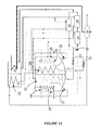
- FIGURE 12 illustrates one more alternative schematic diagram of the apparatus for providing both heating and refrigeration using a single-effect vapor absorption cycle, wherein the streams of the refrigerant-absorbent mixture, typically Li-Br and water, leaving the absorbers (High pressure and low pressure) are mixed and pumped to the vapor generator 14 and the hot water first enters the condenser 22 and then flows into the high pressure absorber 28.
- the embodiment as disclosed in FIGURE 12 operates in a similar manner as aforementioned in the FIGURE 10 .
- the refrigerant-absorbent solution generated in the ABSH 28 and the ABSL 32 is mixed after exiting the shell 25 and the shell 35, respectively.
Abstract
Description
- The present invention relates to a system for generating hot water.
Further, the present invention also relates to a system for obtaining refrigeration. - Many industrial processes require hot water in the range of 60 - 90 °C for heating applications, like paint booth in automobile industry, paper industry, food industry, hotels, and the like. Extensive amount of energy is consumed during the heating application, which adds to the operating costs of the process. Generally, the energy sources used for heating water are fossil fuels including natural gas, liquefied petroleum gas, oil, or solid fuels. These fuels may be consumed directly or by the use of electricity, which may be derived from the above mentioned energy sources. Alternatively, hot water can be generated using solar energy, heat pumps, hot water heat recycling or geothermal heating. The hot water thus generated is sent to the application point where it loses the heat and is then recycled to the hot water generating system. These industries also normally require chilled water/refrigeration for the various process applications.
- Refrigeration is commonly used in industries to liquefy gases like oxygen, nitrogen, propane and methane; in compressed air purification to condense water vapor from compressed air to reduce its moisture content; in oil refineries, chemical plants and petrochemical plants to maintain a low process temperature; and metallurgy industries to temper steel and cutlery. A heat pump is ideal for industrial applications that require both heating and cooling water, wherein the same mechanical refrigeration system can be used to obtain both the effects. With stringent pollution control regulations, application of heat pumps in industries has become important, since the technology helps to reduce emissions, improves efficiency, and limits the use of ground water for cooling. Also, heat pumps are efficient heating and cooling systems that significantly reduce the energy costs.
- The heat pumps commonly used in industrial operations are based on a vapor compression or a vapor absorption cycle. Absorption heat pumps are thermally driven, which means that heat rather than mechanical energy is supplied to drive the cycle. Further, absorption heat pumps for space conditioning are often gas-fired, while industrial installations are usually driven by high-pressure steam or waste heat.
- The absorption systems utilize the ability of liquids or salts to absorb vapors of a working fluid to obtain the heating and the cooling effect.
- The vapor compression cycle uses high grade energy from mechanical inputs while the vapor absorption cycle uses energy input from waste heat or heat derived from solar collectors. Thus, vapor absorption heat pumps substantially reduce the operating costs as they use low-grade waste heat. Also, the vapor absorption systems use non-ozone depleting refrigerants (water) and require much lesser electricity compared to the vapor compression systems. These systems are even more beneficial for industrial applications where waste heat can be used to generate steam/hot water.
- The need for energy conservation has been highlighted by concerns about the environment, leading to development of energy efficient heating and cooling systems. Increased attention has been directed towards development of cost-effective and efficient heat pumps, that can provide heating and cooling, thus, reduce the energy consumption. As a result, the vapor absorption systems are gaining favor over conventional vapor compression heat pumps in industrial applications, as they use little energy and are environmental friendly.
- The basic vapor absorption cycle employs two fluids, the refrigerant and the absorbent. Most commonly, lithium bromide (Li-Br) - water are used as the absorbent-refrigerant pair. In the absorption cycle the low-pressure refrigerant vapor is absorbed into the absorbent releasing a large amount of heat. The liquid refrigerant/absorbent solution is pumped to a high-operating pressure generator, where heat is provided from a gas burner, steam, hot water or hot gases. The heat causes the refrigerant to desorb from the absorbent and vaporize. These vapors flow to a condenser, where the heat is rejected and the refrigerant is condensed to a high-pressure liquid. This liquid refrigerant is then sent to a low-pressure evaporator, where it evaporates by absorbing heat and providing the cooling effect. The concentrated absorbent in the generator is then sent to the absorber, where it is recombined with the low-pressure refrigerant vapors returning from the evaporator, repeating the cycle. The vapor absorption machines can be used for heating applications by passing the hot refrigerant (water) vapors directly from the high temperature generator to the evaporator. These systems utilize heat source such as steam, hot water or hot gases leaving a boiler, turbine or engine generators.
- Commercially, absorption heat pumps can be single-effect or multi-effect. The process discussed above discloses the working of a single-effect vapor absorption system. In single-effect absorption systems, the heat released during the chemical process of absorbing refrigerant vapor into the absorbent rich-stream, is rejected to the environment. In a multi-effect absorption system, some of this energy is utilized as the driving force to generate more refrigerant vapors. The more vapor generated per unit of heat input, greater the cooling capacity and higher the overall operating efficiency. A double-effect absorption system uses two generators including a high temperature and a low temperature generator, paired with a single condenser, absorber, and evaporator.
- The conventional vapor absorption systems can only generate hot water up to 40 - 43 °C, thus, limiting the applications of these systems in industries. Also, these systems can only be used for heating applications by passing the hot refrigerant (water) vapors directly from the high temperature generator to the evaporator. During this operation the vapor absorption system can only function as hot water generator and simultaneous refrigeration effect cannot be obtained. In conventional type of heating-cooling systems, switching between cooling operations and heating operations can be complicated and additional components like generators, pumps and chillers may be required. This adds to the initial capital investment and the operation and maintenance costs in terms of heat and electrical inputs and utilities. Therefore, a suitable system is required that will simultaneously provide heating and refrigeration effect without any additional components and costs.
- Several efforts have been made for providing a vapor absorption heat pump which provides simultaneous heating and cooling effect, some of these works are listed in the prior art cited below:
-
US 6,405,551B discloses a heating apparatus provided with a refrigeration cycle which can be used for heating, cooling and supplying hot water. The apparatus as disclosed inUS 6,405,551 comprises a compressor, a condenser, an evaporator and a first and a second heat exchanger. The first heat exchanger is always used as a heating medium for feed water or bath water while the second heat exchanger is used to provide either heating or cooling by selectively operating the heat exchanger as a condenser or an evaporator, by adequately switching the refrigeration ducts. The apparatus as disclosed inUS 6,405,551 , is primarily used to provide hot water having temperature up to 60 °C and suitable for household applications. -
WO2009/063494A2 discloses a Li-Br vapor absorption machine for providing refrigeration effect. The machine as disclosed inWO2009/063494 comprises of a high temperature generator connected to a furnace to receive a direct heat input by combustion of solid fuels. The machine as disclosed inWO2009/063494 is only used to provide a refrigeration effect. Large quantity of energy consumption and higher CO2 emissions, are some of the drawbacks of the machine as disclosed inW02009/063494 . - Therefore, there is felt a need for a system that will simultaneously provide the heating and the cooling effect, utilize less energy, reduce CO2 emissions, reduce the operating costs and is suitable for various applications.
- An object of the present invention is to provide an apparatus for dual-purpose application of heating and refrigeration.
- Another object of the present invention is to provide an apparatus which substantially reduces the quantity of energy utilized to obtain the heating and refrigeration simultaneously.
- Still another object of the present invention is to provide a system that substantially reduces the quantity of fuel required for generating hot water as compared to the conventional hot water generators.
- Yet another object of the present invention is to provide an apparatus for obtaining refrigeration which does not use chlorofluorocarbons and thus reduces the carbon dioxide emissions.
- One more object of the present invention is to provide an apparatus which does not require additional electrical or heat input to provide the refrigeration.
- Still one more object of the present invention is to provide an apparatus for obtaining heating and refrigeration which reduces the overall initial capital investment.
- Yet one more object of the present invention is to provide an apparatus for providing heating and refrigeration which reduces the scope of utilities used in day-to-day handling operation thus reducing the operating costs.
- An additional object of the present invention is to provide an apparatus which can be used to provide only heating or only refrigeration.
- In accordance with the present invention, there is provided an apparatus for providing both heating and refrigeration, only refrigeration and only heating, under the conditions of high temperature heat input and low temperature heat input, said apparatus comprising a condenser, a vapor generator, a low pressure evaporator, a low pressure absorber, a high pressure evaporator, a high pressure absorber, a flash heat exchanger, a first low temperature heat exchanger, a second low temperature heat exchanger and a heat recovery unit, optionally comprising a low temperature generator, a drain heat exchanger and a high temperature heat exchanger;
characterized in that: - the condenser is connected selectively to a set of equipment selected from a group consisting of the following sets: (i) the high pressure absorber, the flash heat exchanger and the drain heat exchanger; and (ii) the high pressure absorber, the heat recovery unit, the flash heat exchanger and the drain heat exchanger; and (iii) the high pressure absorber; and (iv) the high pressure absorber and the flash heat exchanger; and (v) the high pressure absorber, the heat recovery unit and the flash heat exchanger;
- the vapor generator is connected selectively to a set of equipment selected from a group consisting of the following sets: (i) the low temperature generator, the high temperature heat exchanger and the heat recovery unit; and (ii) the low temperature generator, the low pressure evaporator, the high temperature heat exchanger and the heat recovery unit; and (iii) the heat recovery unit, the first low temperature heat exchanger and the second low temperature heat exchanger;
- the low pressure evaporator cooperating with the low pressure absorber is connected selectively to a set of equipment selected from a group consisting of the following sets: (i) the high pressure evaporator; and (ii) the vapor generator;
- the low pressure absorber cooperating with the low pressure evaporator is connected selectively to a set of equipment selected from a group consisting of the following sets: (i) the high pressure evaporator, the first low temperature heat exchanger and the flash heat exchanger; and (ii) the high pressure evaporator, the first low temperature heat exchanger, the flash heat exchanger and the high temperature heat exchanger; and (iii) the high pressure absorber; and (iv) the flash heat exchanger, the first low temperature heat exchanger and the high temperature heat exchanger; and (v) the high pressure evaporator, the flash heat exchanger and the second low temperature heat exchanger; and (vi) the high pressure evaporator, the flash heat exchanger, the first low temperature heat exchanger and the second low temperature heat exchanger;
- the high pressure evaporator cooperating with the high pressure absorber is connected selectively to a set of equipment selected from a group consisting of the following sets: (i) the low pressure evaporator, the low pressure absorber and the flash heat exchanger; and (ii) the low pressure evaporator;
- the high pressure absorber cooperating with the high pressure evaporator is connected selectively to a set of equipment selected from a group consisting of the following sets: (i) the condenser, the heat recovery unit, the first low temperature heat exchanger, the flash heat exchanger and the second low temperature heat exchanger; and (ii) the condenser, the first low temperature heat exchanger, the flash heat exchanger and the second low temperature heat exchanger; and (iii) the condenser, the heat recovery unit, the first low temperature heat exchanger, the flash heat exchanger, the high temperature heat exchanger and the second low temperature heat exchanger; and (iv) the condenser and the low pressure absorber; and (v) the condenser, the heat recovery unit and the first low temperature heat exchanger; and (vi) the condenser and the first low temperature heat exchanger; and (vii) the condenser, the heat recovery unit, the flash heat exchanger and the first low temperature heat exchanger; and (viii) the condenser, the flash heat exchanger and the first low temperature heat exchanger;
- the flash heat exchanger is connected selectively to a set of equipment selected from a group consisting of the following sets: (i) the condenser, the high pressure evaporator, the low pressure absorber, the high pressure absorber and the drain heat exchanger; and (ii) the low pressure absorber and the drain heat exchanger; and (iii) the condenser, the high pressure evaporator, the low pressure absorber and the second low temperature heat exchanger; and (iv) the condenser, the high pressure evaporator, the low pressure absorber, the high pressure absorber and the second low temperature heat exchanger;
- the first low temperature heat exchanger is connected selectively to a set of equipment selected from a group consisting of the following sets: (i) the low pressure absorber, the high pressure absorber and the second low temperature heat exchanger; and (ii) the low pressure absorber and the second low temperature heat exchanger; and (iii) the high pressure absorber and the vapor generator; and (iv) the low pressure absorber, the high pressure absorber and the vapor generator;
- the second low temperature heat exchanger is connected selectively to a set of equipment selected from a group consisting of the following sets: (i) the high pressure absorber, the first low temperature heat exchanger, the high temperature heat exchanger and the low temperature generator; and (ii) the first low temperature heat exchanger and the high temperature heat exchanger; and (iii) the low pressure absorber, the flash heat exchanger and the vapor generator;
- the heat recovery unit is connected selectively to a set of equipment selected from a group consisting of the following sets: (i) the high pressure absorber and the vapor generator; and (ii) the condenser and the vapor generator; and (iii) the vapor generator;
- the low temperature generator is connected selectively to a set of equipment selected from a group consisting of the following sets: (i) the vapor generator, the high temperature heat exchanger, the drain heat exchanger and the second low temperature heat exchanger; and (ii) the vapor generator, the drain heat exchanger and the second low temperature heat exchanger;
- the drain heat exchanger is connected selectively to a set of equipment selected from a group consisting of the following sets: (i) the low temperature generator, the condenser, the high temperature heat exchanger and the flash heat exchanger; and (ii) the low temperature generator, the condenser and the flash heat exchanger; and (iii) the flash heat exchanger and the high temperature heat exchanger; and
- the high temperature heat exchanger is connected selectively to a set of equipment selected from a group consisting of the following sets: (i) the vapor generator, the low temperature generator, the second low temperature heat exchanger and the drain heat exchanger; and (ii) the vapor generator, the low temperature generator and the second low temperature heat exchanger; and (iii) the vapor generator, the second low temperature heat exchanger and the drain heat exchanger; and (iv) the vapor generator, the second low temperature heat exchanger, the low pressure absorber and the high pressure absorber; and (v) the vapor generator, the low pressure absorber, second low temperature heat exchanger and the drain heat exchanger.
- The invention will now be described with reference to the accompanying drawings, in which;
-
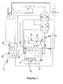
Figure 1 illustrates a schematic diagram of an apparatus for providing heating and refrigeration using a double-effect vapor absorption cycle; -
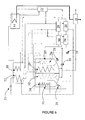
Figure 2 illustrates an alternative schematic diagram of the apparatus for providing heating and refrigeration using a double-effect vapor absorption cycle; -
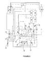
Figure 3 illustrates one more alternative schematic diagram of the apparatus for providing heating and refrigeration using a double-effect vapor absorption cycle; -
Figure 4 illustrates still one more alternative schematic diagram of the apparatus for providing heating and refrigeration using a double-effect vapor absorption cycle; -
Figure 5 illustrates yet one more alternative schematic diagram of the apparatus for providing heating and refrigeration using a double-effect vapor absorption cycle; -
Figure 6 illustrates still another alternative schematic diagram of the apparatus for providing heating and refrigeration using a double-effect vapor absorption cycle; -
Figure 7 illustrates yet another alternative schematic diagram of the apparatus for providing heating and refrigeration using a double-effect vapor absorption cycle; -
Figure 8 illustrates a schematic diagram of the apparatus for providing only refrigeration, showing an inbuilt logic control for switching from heating and refrigeration to only refrigeration; -
Figure 9 illustrates a schematic diagram of the apparatus for providing only heating, showing an inbuilt logic control for switching from heating and refrigeration to only heating; -
Figure 10 illustrates a schematic diagram of an apparatus for providing heating and refrigeration using a single-effect vapor absorption cycle; -
Figure 11 illustrates an alternative schematic diagram of the apparatus for providing heating and refrigeration using a single-effect vapor absorption cycle; -
Figure 12 illustrates one more alternative schematic diagram of the apparatus for providing heating and refrigeration using a single-effect vapor absorption cycle; and -
Figure 13 illustrates still one more alternative schematic diagram of the apparatus for providing heating and refrigeration using a single-effect vapor absorption cycle. - The invention will now be described with reference to the accompanying drawings which do not limit the scope and ambit of the invention. The description provided is purely by way of example and illustration.
- The present invention envisages an apparatus for providing both heating and refrigeration, only refrigeration, and only heating, and a method thereof. The apparatus in accordance with the present invention comprises a condenser (COND), a vapor generator (GEN), a low pressure evaporator (EVAL), a low pressure absorber (ABSL), a high pressure evaporator (EVAH), a high pressure absorber (ABSH), a flash heat exchanger (FHE), a first low temperature heat exchanger (LTHE1), a second low temperature heat exchanger (LTHE2) and a heat recovery unit (HR), further optionally comprising a low temperature generator (LTG), a drain heat exchanger (DHE) and a high temperature heat exchanger (HTHE). The refrigerant-absorbent pair used in the apparatus of the present invention is selected from a group consisting of water-lithium bromide, ammonia-water and the like
- In accordance with one embodiment of the present invention,
FIGURE 1 illustrates a schematic diagram of an apparatus for providing both heating and refrigeration using a double-effect vapor absorption cycle, under the conditions of high temperature heat input, wherein the refrigerant-absorbent mixture, typically Li-Br and water, first enters into the vapor generator and hot water first enters the condenser and then the high pressure absorber. The embodiment as disclosed inFIGURE 1 , comprises feeding a refrigerant-absorbent solution from theHTHE 12 to theGEN 14. TheGEN 14 is provided with a high temperature heat input having temperature in the range of 130 - 220 °C, which boils the refrigerant- absorbent solution entering theGEN 14 to generate a concentrated absorbent solution and refrigerant vapors. TheGEN 14 provided in the double-effect vapor absorption cycle is typically a high temperature generator. The high temperature heat input used in theGEN 14 typically consists of steam, superheated water, by combustion of fuel or exhaust gas. After extracting heat from the heat input in theGEN 14, the left over heat is reclaimed in theHR 16, which is provided to reclaim optimum quantity of heat input in the double-effect vapor absorption cycle and utilize it to enhance the heating effect thus provided. - The concentrated absorbent solution from the
GEN 14 is sent to the HTHE 12 for losing the heat. The concentrated absorbent solution from theHTHE 12 is fed to theLTG 18. The refrigerant vapors after leaving theGEN 14 are sent through the heat exchanger tubes of theLTG 18. The vapors act as a further heating source for the concentrated absorbent solution, thus concentrating it further and consequently condensing the vapor stream to produce a refrigerant condensate which is sent to theDHE 20 for further extraction of heat and refrigerant vapors. The concentrated absorbent solution, thus obtained in theLTG 18 is the most concentrated absorbent solution achieved using the present process cycle. The concentrated absorbent solution from theLTG 18 is sent to theLTHE2 29, where the heat gained by the absorbent solution in theLTG 18 from the refrigerant vapors is extracted. The concentrated absorbent solution stream leaving theLTHE2 29 is bifurcated, wherein the first stream is sent to the LTHE1 30 for further extraction of heat and the second stream is fed to theABSH 28. - The refrigerant condensate after passing through the
DHE 20 and the refrigerant vapors from theLTG 18 are sent to theCOND 22, where the refrigerant is further condensed. The step of primary condensing the refrigerant vapors before passing through theCOND 22 helps in reducing the condenser duty. Hot water, having temperature in the range of 45 - 90 °C, is pumped by pumping means 21 to theCOND 22, through the heat exchanger tubes of theCOND 22. The condensed refrigerant leaving theCOND 22 is passed through theFHE 24. In theFHE 24, the condensed refrigerant is further cooled before feeding it to theEVAH 26; this minimizes the refrigerant flash losses in theEVAH 26 that can be caused due to the high temperature of the condensed refrigerant, thus, improving the efficiency of the apparatus. - In
Figure 1 , numeral 25 represents a shell comprising theABSH 28 and theEVAH 26. By maintaining a high-pressure in theABSH 28 and theEVAH 26 in theshell 25, the condensed refrigerant is vaporized. TheEVAH 26 is provided with water through the evaporator heat exchanger tubes. During the cycle, water exchanges heat with the condensed refrigerant in theEVAH 26. The condensed refrigerant fed to theEVAH 26 absorbs heat from water circulating through the evaporator tubes and forms refrigerant vapors. The refrigerant vapors thus released in theEVAH 26 are absorbed by the concentrated absorbent solution fed to theABSH 28. After absorbing the refrigerant vapors, the concentrated absorbent solution in theABSH 28 becomes dilute or weak and exits theABSH 28 as the refrigerant-absorbent solution. Heat is liberated during the refrigerant vapor absorption process, referred to as the heat of dilution. - The hot water from the
COND 22 is fed to theABSH 28 through the heat exchanger tubes of the absorber, wherein the hot water gains the heat of dilution produced during the refrigerant vapor absorption process. The hot water leaving theABSH 28 has a temperature in the range of 50 - 98 °C and is used for the heating applications. The hot water exiting theABSH 28 is fed to theHR 16. In theHR 16, the hot water further extracts heat from the heat input fed to theGEN 14, producing further heated water, which is used for subsequent applications. - In
Figure 1 , numeral 35 represents a shell comprising theABSL 32 and theEVAL 34. The concentrated absorbent solution after losing heat in theLTHE1 30 is fed to theABSL 32. The water from theEVAH 26 is circulated to theABSL 32 by the pumping means 21. TheEVAL 34 is fed with water having temperature in the range of 5 - 40 °C through the heat exchanger tubes. The condensed refrigerant from theFHE 24 after passing through theEVAH 26 is divided into two streams: the first stream is sent to theEVAL 34 via the pumping means 21 and the second stream is recycled back to theEVAH 26 via the pumping means 21. By maintaining a low-pressure in theABSL 32 and theEVAL 34 in theshell 35, the condensed refrigerant vaporizes at a low temperature. The vaporizing causes the refrigerant to absorb heat from the water circulated through the tubes of theEVAL 34, thus lowering the temperature of the refrigerant and producing refrigerant vapors and cooling the water circulated therein up to a temperature of 0 - 35 °C. The refrigerant vapors produced in theEVAL 34 are absorbed by the concentrated absorbent solution fed to theABSL 32. The concentrated absorbent solution after absorbing the refrigerant vapors becomes dilute. The process of refrigerant absorption produces heat of dilution which is absorbed by the water circulated through the heat exchanger tubes of theABSL 32. The water gains heat in theABSL 32 is recycled to theEVAH 26 for losing the heat, thus completing the loop. The refrigerant stream leaving theEVAL 34 is recycled back to theEVAL 34 via the pumping means 21. - The refrigerant-absorbent solutions generated in the
ABSL 32 and theABSH 28 are mixed after exiting theshell 35 and theshell 25, respectively. The mixture of refrigerant-absorbent solution is fed through the pumping means 21 to the heat exchangers. The refrigerant-absorbent solution stream from theABSL 32 and theABSH 28 is bifurcated, wherein the first stream enters theLTHE1 30 and the second stream enters theFHE 24. In theLTHE1 30 the refrigerant-absorbent solution extracts heat from the concentrated absorbent solution fed therein. From theLTHE1 30 the refrigerant-absorbent solution is fed to theLTHE2 29 wherein the refrigerant-absorbent solution further extracts heat from the concentrated absorbent solution fed to theLTHE2 29 from theLTG 18. The step helps in reducing the temperature of the concentrated absorbent solution from theLTG 18 before feeding it to the absorbers ABSH 28 andABSL 32. In theFHE 24, the refrigerant-absorbent solution absorbs heat from the condensed refrigerant fed to theFHE 24 from theCOND 22, this helps in reducing the temperature of the condensed refrigerant before it is fed to theEVAH 26. After passing through theFHE 24 the refrigerant-absorbent solution is fed to theDHE 20. In theDHE 20 the refrigerant-absorbent solution extracts heat from the refrigerant condensate received therein from theLTG 18, wherein the temperature of the refrigerant-absorbent solution increases and the refrigerant condensate is suitably cooled before feeding to theCOND 22. - The heated refrigerant-absorbent solution leaving the
LTHE2 29 andDHE 20 is mixed and fed to theHTHE 12. In theHTHE 12 the refrigerant-absorbent solution absorbs heat from the concentrated absorbent solution leaving theGEN 14. The refrigerant-absorbent solution after gaining heat in theHTHE 12 is fed to theHTG 14, where the refrigerant-absorbent solution is boiled to generate a concentrated absorbent solution. The concentrated absorbent solution from theHTHE 12 is fed to theLTG 18 after exchanging heat with the refrigerant-absorbent solution. The apparatus as disclosed in theFigure 1 is provided with programmable logic controls (PLC) (not shown in the figure) to provide an automated control over the process cycle. - In accordance with another embodiment of the present invention,
FIGURE 2 illustrates an alternative schematic diagram of the apparatus for providing both heating and refrigeration using a double-effect vapor absorption cycle, under conditions of high temperature heat input, wherein the refrigerant-absorbent mixture, typically Li-Br and water, first enters the vapor generator and the hot water first enters the high pressure absorber and then flows into the condenser. The embodiment as disclosed inFIGURE 2 operates in a similar manner as aforementioned in theFIGURE 1 . However, in the embodiment as disclosed inFIGURE 2 , the hot water with temperature in the range of 45 - 90 °C is first pumped through the pumping means 21 to the heat exchanger tubes of theABSH 28 where in theABSH 28 the hot water absorbs the heat of dilution produced during the refrigerant vapor absorption process in theshell 25. The hot water exiting theABSH 28 is then fed to theCOND 22 wherein the hot water having temperature lower than the condensed refrigerant received in theCOND 22 from theDHE 20 is used to further condense the condensed refrigerant received therein, thus generating a further condensed refrigerant and further heated water having temperature in the range of 50 - 98 °C which is used for the heating applications. The heated water from theCOND 22 is fed to theHR 16. In theHR 16, the hot water further extracts heat from the heat input fed in theGEN 14, producing further hot water having which is used for subsequent applications. - In accordance with still another embodiment of the present invention,
FIGURE 3 illustrates one more alternative schematic diagram of the apparatus for providing both heating and refrigeration using a double-effect vapor absorption cycle, wherein the refrigerant-absorbent mixture, typically Li-Br and water, first enters the low temperature generator and the hot water first enters the condenser and then flows into the high pressure absorber. The embodiment as disclosed inFIGURE 3 , comprises feeding a refrigerant-absorbent solution to theLTG 18, wherein in theLTG 18 refrigerant vapors are used to provide a heat source to the refrigerant-absorbent solution received therein, such that a moderately concentrated refrigerant-absorbent solution and refrigerant condensate and vapors are generated in theLTG 18 wherein the refrigerant condensate is sent to theDHE 20 for further extraction of heat. - The moderately concentrated solution from the
LTG 18 is received in theHTHE 12 where it gains heat to produce a heated moderately concentrated absorbent solution. The heated moderately concentrated absorbent solution from theHTHE 12 is sent to theGEN 14 where using a high temperature heat input having temperature in the range of 130 - 220 °C the moderately concentrated absorbent solution is boiled to form a concentrated absorbent and refrigerant vapors. TheGEN 14 provided in the double-effect vapor absorption cycle is typically a high temperature generator. The high temperature heat input used in theGEN 14 typically consists of steam, superheated water, by combustion of fuel or exhaust gas. After extracting heat from the heat input in theGEN 14, the left over heat is reclaimed in theHR 16, which is provided to reclaim optimum quantity of heat input in the double-effect vapor absorption cycle and utilize it to enhance the heating thus provided. - The refrigerant vapors from the
GEN 14 are fed to theLTG 18 which are used to provide the heat source to the refrigerant-absorbent solution and produce the moderately concentrated absorbent. The concentrated absorbent from theGEN 14 is passed through theHTHE 12 where it exchanges heat with the moderately concentrated solution received therein, thus, heating the moderately concentrated solution. The concentrated absorbent, thus obtained in theGEN 14 is the most concentrated absorbent solution achieved using the present process cycle. The concentrated absorbent from theGEN 14 is sent to theLTHE2 29, where the heat from the concentrated absorbent is further extracted to generate a cooled concentrated absorbent. The cooled concentrated absorbent leaving theLTHE2 29 is bifurcated, wherein the first stream is sent to the LTHE1 30 for further extraction of heat to generate a further cooled concentrated absorbent and the second stream of the cooled concentrated absorbent is fed to theABSH 28. - The refrigerant condensate after passing through the
DHE 20 and the refrigerant vapors from theLTG 18 are sent to theCOND 22, where the refrigerant is further condensed. The step of primary condensing the refrigerant vapors before passing through theCOND 22 helps in reducing the condenser duty. Hot water, having temperature in the range of 45 - 90 °C, is pumped by pumping means 21 to theCOND 22, through the heat exchanger tubes of theCOND 22. The condensed refrigerant leaving theCOND 22 is passed through theFHE 24. In theFHE 24, the condensed refrigerant is further cooled before feeding it to theEVAH 26; this minimizes the refrigerant flash losses in theEVAH 26 that can be caused due to the high temperature of the condensed refrigerant, thus, improving the efficiency of the apparatus. - In
FIGURE 3 , numeral 25 represents a shell comprising theABSH 28 and theEVAH 26. By maintaining a high-pressure in theABSH 28 and theEVAH 26 in theshell 25, the condensed refrigerant is vaporized. TheEVAH 26 is provided with water through the evaporator heat exchanger tubes. During the cycle, the water exchanges heat with the condensed refrigerant in theEVAH 26. The condensed refrigerant fed to theEVAH 26 absorbs heat from the water circulating through the evaporator tubes and forms refrigerant vapors. The refrigerant vapors thus released in theEVAH 26 are absorbed by the concentrated absorbent solution fed to theABSH 28. After absorbing the refrigerant vapors, the concentrated absorbent solution in theABSH 28 becomes dilute or weak and exits theABSH 28 as the refrigerant-absorbent solution. Heat is liberated during the refrigerant vapor absorption process, referred to as the heat of dilution. - The hot water from the
COND 22 is fed to theABSH 28 through the heat exchanger tubes of the absorber, wherein the hot water gains the heat of dilution produced during the refrigerant vapor absorption process. The hot water leaving theABSH 28 has a temperature in the range of 50 - 98 °C and is used to provide the heating applications. The hot water exiting theABSH 28 is fed to theHR 16. In theHR 16, the hot water further extracts heat from the heat input fed to theGEN 14, producing further hot water. - In
FIGURE 3 , numeral 35 represents a shell comprising theABSL 32 and theEVAL 34. The cooled concentrated absorbent after further losing heat in theLTHE1 30 forms a further cooled concentrated absorbent which is fed to theABSL 32. The water from theEVAH 26 is circulated to theABSL 32 by the pumping means 21. TheEVAL 34 is fed with water having temperature in the range of 5 - 40 °C through the heat exchanger tubes. The condensed refrigerant from theFHE 24 after passing through theEVAH 26 is divided into two streams: the first stream is sent to theEVAL 34 via the pumping means 21 and the second stream is recycled back to theEVAH 26 via the pumping means 21. By maintaining a low-pressure in theABSL 32 and theEVAL 34 in theshell 35, the condensed refrigerant vaporizes at a low temperature. The vaporizing causes the refrigerant to absorb heat from the water circulated through the tubes of theEVAL 34, thus lowering the temperature of the refrigerant and producing refrigerant vapors and cooling the water circulated therein up to a temperature of 0 - 35 °C. The refrigerant vapors produced in theEVAL 34 are absorbed by the concentrated absorbent solution fed to theABSL 32. The concentrated absorbent solution after absorbing the refrigerant vapors becomes dilute. The process of refrigerant absorption produces heat of dilution which is absorbed by the water circulated through the heat exchanger tubes of theABSL 32. The water gains heat in theABSL 32 is recycled to theEVAH 26 for losing the heat, thus completing the loop. The refrigerant stream leaving theEVAL 34 is recycled back to theEVAL 34 via the pumping means 21. - The refrigerant-absorbent solutions generated in the
ABSL 32 and theABSH 28 are mixed after exiting theshell 35 and theshell 25, respectively. The mixture of refrigerant-absorbent solution is fed through the pumping means 21 to the heat exchangers. The refrigerant-absorbent solution stream from theABSL 32 and theABSH 28 is bifurcated wherein the first stream enters theLTHE1 30 and the second stream enters theFHE 24. In theLTHE1 30 the refrigerant-absorbent solution extracts heat from the cooled concentrated absorbent fed therein from theLTHE2 29. From theLTHE1 30 the refrigerant-absorbent solution is fed to theLTHE2 29 wherein the refrigerant-absorbent solution further extracts heat from the concentrated absorbent fed to theLTHE2 29 from theHTHE 12. The step helps in reducing the temperature of the concentrated absorbent from the HTHE 12 before feeding it to the absorbers ABSH 28 andABSL 32. In theFHE 24, the refrigerant-absorbent solution absorbs heat from the condensed refrigerant fed to theFHE 24 from theCOND 22, this helps in reducing the temperature of the condensed refrigerant before it is fed to theEVAH 26. After passing through theFHE 24 the refrigerant-absorbent solution is fed to theDHE 20. In theDHE 20 the refrigerant-absorbent solution extracts heat from the refrigerant condensate received therein from theLTG 18, wherein the temperature of the refrigerant-absorbent solution increases and the refrigerant condensate is suitably cooled before feeding to theCOND 22. - The heated refrigerant-absorbent solution leaving the
LTHE2 29 andDHE 20 is mixed and fed to theLTG 18. In theLTG 18 the refrigerant-absorbent solution takes heat from the refrigerant vapors leaving theGEN 14 to produce the moderately concentrated absorbent solution, thus completing the process cycle. The apparatus as disclosed in theFIGURE 3 is provided with programmable logic controls (PLC) (not shown in the figure) to provide an automated control over the process cycle. - In accordance with yet another embodiment of the present invention,
FIGURE 4 illustrates still one more alternative schematic diagram of the apparatus for providing both heating and refrigeration using a double-effect vapor absorption cycle, under conditions of high temperature heat input, wherein the refrigerant-absorbent mixture, typically Li-Br and water, first enters the low temperature generator and the hot water first enters the high pressure absorber and then flows into the condenser. The embodiment as disclosed inFIGURE 4 operates in a similar manner as aforementioned in theFIGURE 3 . However, in the embodiment as disclosed inFIGURE 4 , the hot water with temperature in the range of 45 - 90 °C is first pumped through the pumping means 21 to the heat exchanger tubes of theABSH 28 where in theABSH 28 the hot water absorbs the heat of dilution produced during the refrigerant vapor absorption process in theshell 25. The hot water exiting theABSH 28 is then fed to theCOND 22 wherein the hot water having temperature lower than the condensed refrigerant received in theCOND 22 from theDHE 20 is used to further condense the condensed refrigerant received therein, thus generating a further condensed refrigerant and further heated water having temperature in the range of 50 - 98 °C which is used for the heating applications. The heated water from theCOND 22 is fed to theHR 16. In theHR 16, the hot water further extracts heat from the heat input fed in theGEN 14, producing further heated water which is used for subsequent applications. - In accordance with one more embodiment of the present invention,
FIGURE 5 illustrates yet one more alternative schematic diagram of the apparatus for providing both heating and refrigeration using a double-effect vapor absorption cycle, wherein the refrigerant-absorbent mixture, typically Li-Br and water, leaving the low temperature heat exchanger and the drain heat exchanger bifurcates and a portion enters the low temperature generator and another portion enters the vapor generator. The embodiment as disclosed inFIGURE 5 , comprises feeding a refrigerant- absorbent solution from theHTHE 12 to theGEN 14. TheGEN 14 is provided with a high temperature heat input having temperature in the range of 130 - 220 °C, which boils the refrigerant- absorbent solution entering theGEN 14 to generate a concentrated absorbent solution and refrigerant vapors. TheGEN 14 provided in the double-effect vapor absorption cycle is typically a high temperature generator. The high temperature heat input used in theGEN 14 typically consists of steam, superheated water, by combustion of fuel or exhaust gas. After extracting heat from the heat input in theGEN 14, the left over heat is reclaimed in theHR 16, which is provided to reclaim optimum quantity of heat input in the double-effect vapor absorption cycle and utilize it to enhance the heating thus provided. - The concentrated absorbent solution from the
GEN 14 is received in theHTHE 12 wherein heat from the concentrated absorbent leaving theGEN 14 is extracted to produce a heat extracted concentrated absorbent. The heat extracted concentrated absorbent from theHTHE 12 is fed to theLTHE2 29 for further extracting the heat and thus obtaining a cooled concentrated absorbent. The refrigerant vapors generated in theGEN 14 are fed to theLTG 18 where in theLTG 18 the vapors are used as a heat source to concentrate a refrigerant-absorbent solution received therein, thus providing a concentrated absorbent solution which is fed to theLTHE2 29 from theLTG 18 and a mixture of refrigerant condensate which is fed to theDHE 20 for further extraction of heat and refrigerant vapors which are fed to theCOND 22. The concentrated absorbent solution, thus obtained in theLTG 18 and theGEN 14 is the most concentrated absorbent solution achieved using the present process cycle. The concentrated absorbent solution from theLTG 18 and theGEN 14 is sent to theLTHE2 29, where the heat gained by the concentrated absorbent solution in theLTG 18 and theGEN 14 is extracted and a cooled concentrated absorbent is achieved. The cooled concentrated absorbent solution stream leaving theLTHE2 29 is bifurcated into two streams, wherein the first stream is sent to the LTHE1 30 for further cooling to generate a further cooled concentrated absorbent and the second stream is fed to theABSH 28. - The refrigerant condensate after passing through the
DHE 20 and the refrigerant vapors from theLTG 18 are sent to theCOND 22, where it is further condensed. The step of primary condensing the refrigerant vapors before passing through theCOND 22 helps in reducing the condenser duty. Hot water, having temperature in the range of 45 - 90 °C, is pumped by pumping means 21 to theCOND 22, through the heat exchanger tubes of theCOND 22. The condensed refrigerant leaving theCOND 22 is passed through theFHE 24. In theFHE 24, the condensed refrigerant is further cooled before feeding it to theEVAH 26; this minimizes the refrigerant flash losses in theEVAH 26 that can be caused due to the high temperature of the condensed refrigerant, thus, improving the efficiency of the apparatus. - In
Figure 5 , numeral 25 represents a shell comprising theABSH 28 and theEVAH 26. By maintaining a high-pressure in theABSH 28 and theEVAH 26 in theshell 25, the condensed refrigerant is vaporized. TheEVAH 26 is provided with water through the evaporator heat exchanger tubes. During the cycle, the water exchanges heat with the condensed refrigerant in theEVAH 26. The condensed refrigerant fed to theEVAH 26 absorbs heat from the water circulating through the evaporator tubes and forms refrigerant vapors. The refrigerant vapors thus released in theEVAH 26 are absorbed by the concentrated absorbent solution fed to theABSH 28. After absorbing the refrigerant vapors, the concentrated absorbent solution in theABSH 28 becomes dilute or weak and exits theABSH 28 as the refrigerant-absorbent solution. Heat is liberated during the refrigerant vapor absorption process, referred to as the heat of dilution. - The hot water from the
COND 22 is fed to theABSH 28 through the heat exchanger tubes of the absorber, wherein the hot water gains the heat of dilution produced during the refrigerant vapor absorption process. The hot water leaving theABSH 28 has a temperature in the range of 50 - 98 °C and is used for the heating applications. The hot water exiting theABSH 28 is fed to theHR 16. In theHR 16, the hot water further extracts heat from the heat input fed to theGEN 14, producing further heated water, which is used for subsequent applications. - In
Figure 5 , numeral 35 represents a shell comprising theABSL 32 and theEVAL 34. The concentrated absorbent solution after losing heat in theLTHE1 30 is fed to theABSL 32. The water from theEVAH 26 is circulated to theABSL 32 by the pumping means 21. TheEVAL 34 is fed with water having temperature in the range of 5 - 40 °C through the heat exchanger tubes. The condensed refrigerant from theFHE 24 after passing through theEVAH 26 is divided into two streams: the first stream is sent to theEVAL 34 via the pumping means 21 and the second stream is recycled back to theEVAH 26 via the pumping means 21. By maintaining a low-pressure in theABSL 32 and theEVAL 34 in theshell 35, the condensed refrigerant vaporizes at a low temperature. The vaporizing causes the refrigerant to absorb heat from the water circulated through the tubes of theEVAL 34, thus lowering the temperature of the refrigerant and producing refrigerant vapors and cooling the water circulated therein up to a temperature of 0 - 35 °C. The refrigerant vapors produced in theEVAL 34 are absorbed by the concentrated absorbent solution fed to theABSL 32. The concentrated absorbent solution after absorbing the refrigerant vapors becomes dilute. The process of refrigerant absorption produces heat of dilution which is absorbed by the water circulated through the heat exchanger tubes of theABSL 32. The water gains heat in theABSL 32 is recycled to theEVAH 26 for losing the heat, thus completing the loop. The refrigerant stream leaving theEVAL 34 is recycled back to theEVAL 34 via the pumping means 21. - The refrigerant-absorbent solutions generated in the
ABSL 32 and theABSH 28 are mixed after exiting theshell 35 and theshell 25, respectively. The mixture of refrigerant-absorbent solution is fed through the pumping means 21 to the heat exchangers. The refrigerant-absorbent solution stream from theABSL 32 and theABSH 28 is bifurcated wherein the first stream enters theLTHE1 30 and the second stream enters theFHE 24. In theLTHE1 30 the refrigerant-absorbent solution extracts heat from the cooled concentrated absorbent solution fed therein from theLTHE2 29. From theLTHE1 30 the refrigerant-absorbent solution is fed to theLTHE2 29 wherein the refrigerant-absorbent solution further extracts heat from the concentrated absorbent solution fed to theLTHE2 29 from theLTG 18 and theHTHE 12. The step helps in reducing the temperature of the concentrated absorbent solution from theLTG 18 before feeding it to the absorbers ABSH 28 andABSL 32. In theFHE 24, the refrigerant-absorbent solution absorbs heat from the condensed refrigerant fed to theFHE 24 from theCOND 22, this helps in reducing the temperature of the condensed refrigerant before it is fed to theEVAH 26. After passing through theFHE 24 the refrigerant-absorbent solution is fed to theDHE 20. In theDHE 20 the refrigerant-absorbent solution extracts heat from the refrigerant condensate received therein from theLTG 18, wherein the temperature of the refrigerant-absorbent solution increases and the refrigerant condensate is suitably cooled before feeding to theCOND 22. - The heated refrigerant-absorbent solution leaving the
LTHE2 29 and theDHE 20 are mixed. The mixed heated refrigerant-absorbent solution is then bifurcated wherein the first stream enters theLTG 18 and the second stream enters theGEN 14 via theHTHE 12. The refrigerant-absorbent solution entering theLTG 18 and theGEN 14 is concentrated by using a heat source, thus generating the concentrated absorbent; completing the process cycle in accordance to the present embodiment. The apparatus as disclosed in theFIGURE 5 is provided with programmable logic controls (PLC) (not shown in the figure) to provide an automated control over the process cycle. - In accordance with still one more embodiment of the present invention,
FIGURE 6 illustrates yet another alternative schematic diagram of the apparatus for providing both heating and refrigeration using a double-effect vapor absorption cycle, under conditions of high temperature heat input, wherein the refrigerant-absorbent mixture, typically Li-Br and water, leaving the absorbers bifurcates, a portion enters the low temperature generator and another portion enters the vapor generator. The embodiment as disclosed inFIGURE 6 operates in a similar manner as aforementioned in theFIGURE 5 . However, in the embodiment as disclosed inFIGURE 6 the refrigerant-absorbent solutions generated in theABSL 32 and theABSH 28 are mixed after exiting theshell 35 and theshell 25, respectively. The mixed refrigerant-absorbent solution is then bifurcated. The first stream of the refrigerant-absorbent solution is fed through the pumping means 21 to theheat exchangers LTHE1 30 and the second stream enters theFHE 24. In theLTHE1 30 the refrigerant-absorbent solution extracts heat from the cooled concentrated absorbent solution fed therein from theLTHE2 29. From theLTHE1 30 the refrigerant-absorbent solution is fed to theLTHE2 29 wherein the refrigerant-absorbent solution further extracts heat from the concentrated absorbent solution fed to theLTHE2 29 from theLTG 18 and theHTHE 12. The step helps in reducing the temperature of the concentrated absorbent solution from theLTG 18 before feeding it to the absorbers ABSH 28 andABSL 32. In theFHE 24, the refrigerant-absorbent solution absorbs heat from the condensed refrigerant fed to theFHE 24 from theCOND 22, this helps in reducing the temperature of the condensed refrigerant before it is fed to theEVAH 26. After passing through theFHE 24 the refrigerant-absorbent solution is fed to theDHE 20. In theDHE 20 the refrigerant-absorbent solution extracts heat from the refrigerant condensate received therein from theLTG 18, wherein the temperature of the refrigerant-absorbent solution increases and the refrigerant condensate is suitably cooled before feeding to theCOND 22. The heated refrigerant-absorbent solution leaving theLTHE2 29 and theDHE 20 is sent to theLTG 18 where the refrigerant-absorbent solution absorbs heat from the refrigerant vapors circulated therein to generate the concentrated absorbent which is recycled to theLTHE2 29. - The second stream of the refrigerant-absorbent solution is fed to the
HTHE 12, where the refrigerant-absorbent solution extracts heat from the concentrated absorbent circulated therein from theGEN 14 to generate a heated refrigerant-absorbent solution which is fed to theGEN 14 to obtain the concentrated absorbent and a heat extracted concentrated absorbent which is fed to theLTHE2 29 for cooling; completing the process cycle in accordance to the present embodiment. The apparatus as disclosed in theFigure 6 is provided with programmable logic controls (PLC) (not shown in the figure) to provide an automated control over the process cycle. - In accordance with still one more embodiment of the present invention,
FIGURE 7 illustrates still another alternative schematic diagram of the apparatus for providing both heating and refrigeration using a double-effect vapor absorption cycle, under conditions of high temperature heat input, wherein the refrigerant-absorbent mixture, typically Li-Br and water, first enters the low temperature generator and then bifurcates, a portion enters the vapor generator and another portion flows into the absorbers. The embodiment as disclosed inFIGURE 7 , comprises feeding a refrigerant-absorbent solution to theLTG 18, wherein in theLTG 18 refrigerant vapors are used to provide a heat source to the refrigerant-absorbent solution received therein, such that a moderately concentrated refrigerant-absorbent solution and refrigerant condensate and vapors are generated in theLTG 18 wherein the refrigerant condensate and vapors are sent to theDHE 20 for further extraction of heat. - The moderately concentrated solution from the
LTG 18 is bifurcated and a first portion is received in theHTHE 12 where the moderately concentrated solution gains heat to produce a heated moderately concentrated absorbent solution. The heated moderately concentrated absorbent solution from theHTHE 12 is sent to theGEN 14 where using a high temperature heat input having temperature in the range of 130 - 220 °C the moderately concentrated absorbent solution is boiled to form a concentrated absorbent and refrigerant vapors. TheGEN 14 provided in the double-effect vapor absorption cycle is typically a high temperature generator. The high temperature heat input used in theGEN 14 typically consists of steam, superheated water, by combustion of fuel or exhaust gas. After extracting heat from the heat input in theGEN 14, the left over heat is reclaimed in theHR 16, which is provided to reclaim optimum quantity of heat input in the double-effect vapor absorption cycle and utilize it to enhance the heating thus provided. - The refrigerant vapors from the
GEN 14 are fed to theLTG 18 which are used to provide the heat source to the refrigerant-absorbent solution and produce the moderately concentrated absorbent. The concentrated absorbent from theGEN 14 is passed through theHTHE 12 where it exchanges heat with the moderately concentrated solution received therein, thus, heating the moderately concentrated solution and producing a heat extracted concentrated absorbent. The heat extracted concentrated absorbent from the HTHE 12 along with a second portion of the moderately concentrated solution from theLTG 18 is fed to theLTHE2 29, where the heat from the concentrated absorbent is further extracted to generate a cooled concentrated absorbent. The cooled concentrated absorbent leaving theLTHE2 29 is bifurcated, wherein the first stream is sent to the LTHE1 30 for further extraction of heat to generate a further cooled concentrated absorbent and the second stream of the cooled concentrated absorbent is fed to theABSH 28. - The refrigerant condensate after passing through the
DHE 20 is sent to theCOND 22, where it is further condensed. The step of primary condensing the refrigerant vapors before passing through theCOND 22 helps in reducing the condenser duty. Hot water, having temperature in the range of 45 - 90 °C, is pumped by pumping means 21 to theCOND 22, through the heat exchanger tubes of theCOND 22. The condensed refrigerant leaving theCOND 22 is passed through theFHE 24. In theFHE 24, the condensed refrigerant is further cooled before feeding it to theEVAH 26; this minimizes the refrigerant flash losses in theEVAH 26 that can be caused due to the high temperature of the condensed refrigerant, thus, improving the efficiency of the apparatus. - In
Figure 7 , numeral 25 represents a shell comprising theABSH 28 and theEVAH 26. By maintaining a high-pressure in theABSH 28 and theEVAH 26 in theshell 25, the condensed refrigerant is vaporized. TheEVAH 26 is provided with water through the evaporator heat exchanger tubes. During the cycle, the water exchanges heat with the condensed refrigerant in theEVAH 26. The condensed refrigerant fed to theEVAH 26 absorbs heat from the water circulating through the evaporator tubes and forms refrigerant vapors. The refrigerant vapors thus released in theEVAH 26 are absorbed by the concentrated absorbent solution fed to theABSH 28. After absorbing the refrigerant vapors, the concentrated absorbent solution in theABSH 28 becomes dilute or weak and exits theABSH 28 as the refrigerant-absorbent solution. Heat is liberated during the refrigerant vapor absorption process, referred to as the heat of dilution. - The hot water from the
COND 22 is fed to theABSH 28 through the heat exchanger tubes of the absorber, wherein the hot water gains the heat of dilution produced during the refrigerant vapor absorption process. The hot water leaving theABSH 28 has a temperature in the range of 50 - 98 °C and is used for the heating applications. The hot water exiting theABSH 28 is fed to theHR 16. In theHR 16, the hot water further extracts heat from the heat input fed to theGEN 14, producing further heated water, which is used for subsequent applications. - In
Figure 7 , numeral 35 represents a shell comprising theABSL 32 and theEVAL 34. The cooled concentrated absorbent after further losing heat in theLTHE1 30 forms a further cooled concentrated absorbent which is fed to theABSL 32. The water from theEVAH 26 is circulated to theABSL 32 by the pumping means 21. TheEVAL 34 is fed with water having temperature in the range of 5 - 40 °C through the heat exchanger tubes. The condensed refrigerant from theFHE 24 after passing through theEVAH 26 is divided into two streams: the first stream is sent to theEVAL 34 via the pumping means 21 and the second stream is recycled back to theEVAH 26 via the pumping means 21. By maintaining a low-pressure in theABSL 32 and theEVAL 34 in theshell 35, the condensed refrigerant vaporizes at a low temperature. The vaporizing causes the refrigerant to absorb heat from the water circulated through the tubes of theEVAL 34, thus lowering the temperature of the refrigerant and producing refrigerant vapors and cooling the water circulated therein up to a temperature of 0 - 35 °C. The refrigerant vapors produced in theEVAL 34 are absorbed by the concentrated absorbent solution fed to theABSL 32. The concentrated absorbent solution after absorbing the refrigerant vapors becomes dilute. The process of refrigerant absorption produces heat of dilution which is absorbed by the water circulated through the heat exchanger tubes of theABSL 32. The water gains heat in theABSL 32 is recycled to theEVAH 26 for losing the heat, thus completing the loop. The refrigerant stream leaving theEVAL 34 is recycled back to theEVAL 34 via the pumping means 21. - The refrigerant-absorbent solutions generated in the
ABSL 32 and theABSH 28 are mixed after exiting theshell 35 and theshell 25, respectively. The mixed refrigerant-absorbent solution is fed through the pumping means 21 to the heat exchangers. The refrigerant-absorbent solution stream from theABSL 32 and theABSH 28 is bifurcated wherein the first stream enters theLTHE1 30 and the second stream enters theFHE 24. In theLTHE1 30 the refrigerant-absorbent solution extracts heat from the cooled concentrated absorbent fed therein from theLTHE2 29. From theLTHE1 30 the refrigerant-absorbent solution is fed to theLTHE2 29 wherein the refrigerant-absorbent solution further extracts heat from the concentrated absorbent fed to theLTHE2 29 from theHTHE 12. The step helps in reducing the temperature of the concentrated absorbent from the HTHE 12 before feeding it to the absorbers ABSH 28 andABSL 32. In theFHE 24, the refrigerant-absorbent solution absorbs heat from the condensed refrigerant fed to theFHE 24 from theCOND 22, this helps in reducing the temperature of the condensed refrigerant before it is fed to theEVAH 26. After passing through theFHE 24 the refrigerant-absorbent solution is fed to theDHE 20. In theDHE 20 the refrigerant-absorbent solution extracts heat from the refrigerant condensate received therein from theLTG 18, wherein the temperature of the refrigerant-absorbent solution increases and the refrigerant condensate is suitably cooled before feeding to theCOND 22. - The heated refrigerant-absorbent solution leaving the
LTHE2 29 andDHE 20 is mixed and fed to theLTG 18. In theLTG 18 the refrigerant-absorbent solution takes heat from the refrigerant vapors leaving theGEN 14 to produce the moderately concentrated absorbent solution, thus completing the process cycle. The apparatus as disclosed in theFIGURE 7 is provided with programmable logic controls (PLC) (not shown in the figure) to provide an automated control over the process cycle. - In accordance with yet one more embodiment of the present invention,
FIGURE 8 illustrates a schematic diagram of the apparatus for providing only refrigeration, showing an inbuilt logic control for switching from heating and refrigeration to only refrigeration, under the conditions of high temperature heat input. The embodiment as disclosed inFIGURE 8 comprises theEVAH 26, theABSH 28, theEVAL 34, theABSL 32 and a plurality of valves represented bynumerals EVAH 26 is located in co-operation with theABSH 28 in theshell 25 and theEVAL 34 is located in cooperation with theABSL 32 in theshell 35. - By opening the
valves EVAH 26 and theEVAL 34, water having temperature in the range of 5 - 40 °C is allowed to flow in theEVAH 26 and theEVAL 34. TheEVAH 26 and theEVAL 34 are adapted to receive condensed refrigerant to provide refrigerant vapors and water having temperature in the range of 0 - 35 °C, to provide the refrigeration. By openingvalves ABSH 28 and theABSL 32. TheABSH 28 and theABSL 32 are adapted to receive a concentrated absorbent. The concentrated absorbent absorbs the refrigerant vapors released in theEVAH 26 and theEVAL 34, respectively, to provide a refrigerant-absorbent mixture. During the refrigerant absorption process, heat of dilution is released which is removed by the water circulated through the heat exchanger tubes of theABSH 28 and theABSL 32, thus, generating heated water which is sent to a condenser. The refrigerant-absorbent mixture is sent for further regeneration of concentrated absorbent and refrigerant vapors. - The plurality of
valves EVAH 26, theEVAL 34, theABSH 28 and theABSL 32, to permit the conversion of both heating and refrigeration cycle to only refrigeration. Optionally, an automation means having a control logic (CL), represented by numeral 39a inFIGURE 8 , may be provided to switch the operation of the plurality ofvalves - In accordance with still one more embodiment of the present invention,
FIGURE 9 illustrates a schematic diagram of the apparatus for providing only heating, showing an inbuilt logic control for switching from heating and refrigeration to only heating, under the conditions of high or low temperature heat inputs. The embodiment as disclosed inFIGURE 9 , comprises feeding a refrigerant- absorbent solution from theHTHE 12 to theGEN 14. TheGEN 14 is provided with a high temperature heat input having temperature in the range of 90 - 220 °C, which boils the refrigerant- absorbent solution entering theGEN 14 to generate a concentrated absorbent solution and refrigerant vapors. TheGEN 14 is typically a high temperature generator. The high temperature heat input used in theGEN 14 typically consists of steam, superheated water, by combustion of fuel or exhaust gas. The concentrated absorbent solution from theGEN 14 is received in theHTHE 12 wherein heat from the concentrated absorbent leaving theGEN 14 is extracted by a refrigerant-absorbent mixture to produce a heat extracted concentrated absorbent and a heated refrigerant-absorbent mixture which is fed to theGEN 14. The heat extracted concentrated absorbent from theHTHE 12 is fed to theABSL 32. - A plurality of valves represented in
FIGURE 9 bynumerals GEN 14 and theEVAL 34, and the HTHE 12 and theABSL 32, respectively. The refrigerant vapors released in theGEN 14 are fed to theEVAL 34 through thevalve 37f, wherein thevalve 37f is open when operating the only heating cycle. TheABSL 32 and theEVAL 34 are located inshell 35 in cooperation with each other. Hot water having temperature in the range of 45 - 90 °C is fed through the heat exchanger tubes of theEVAL 34. The hot water circulated in theEVAL 34 extracts heat from the refrigerant vapors thus further heating the water up to a temperature of 50 - 98 °C, to be used for the heating applications. Further, the refrigerant vapors in theEVAL 34 are absorbed by the concentrated absorbent which is sprayed in theABSL 32 from the HTHE 12 throughvalve 37g which is to be kept open during the only heating cycle. - During the refrigerant absorption process, the concentrated absorbent becomes dilute because of absorption of the refrigerant and forms the refrigerant-absorbent mixture which is fed to the
GEN 14 and heat of dilution is released which is absorbed by the hot water circulated through theEVAL 34, thus heating the water even further. The refrigerant-absorbent mixture discharged from theABSL 32 is then fed to theHTHE 12 to further extract heat from the concentrated absorbent received in theHTHE 12 from theGEN 14 before entering theGEN 14 for concentration, thus completing the process cycle, in accordance to the present embodiment. The process as described inFIGURE 9 is typically used to provide only heating. The plurality ofvalves FIGURE 9 , may be provided to switch the operation of the plurality ofvalves - In accordance with an additional embodiment of the present invention,
FIGURE 10 illustrates a schematic diagram of an apparatus for providing both heating and refrigeration using a single-effect vapor absorption cycle, wherein the streams of the refrigerant-absorbent mixture, typically Li-Br and water, leaving the absorbers (high pressure and low pressure) are pumped to thevapor generator 14 by two absorbent pumps and the hot water first enters thecondenser 22 and then flows into thehigh pressure absorber 28. The embodiment as disclosed inFIGURE 10 , comprises feeding a refrigerant- absorbent solution to theGEN 14. TheGEN 14 is provided with a low temperature heat input having temperature in the range of 90 - 170 °C, which boils the refrigerant-absorbent solution entering theGEN 14 to generate a concentrated absorbent solution and subsequently produce refrigerant vapors which are released. The low temperature heat input used in theGEN 14 typically consists of steam, superheated water, by combustion of fuel or exhaust gas. After extracting heat from the heat input in theGEN 14, the left over heat is reclaimed in theHR 16, which is provided to reclaim optimum quantity of heat input in the single-effect vapor absorption cycle and utilize it to enhance the heating thus provided. - The concentrated absorbent solution from the
GEN 14 is received in theLTHE1 30 andLTHE2 29 wherein heat from the concentrated absorbent leaving theGEN 14 is extracted to produce a cooled concentrated absorbent. The cooled concentrated absorbent from the LTHE1 30 andLTHE2 29 is fed to the absorbers. The concentrated absorbent solution, thus obtained in theGEN 14 is the most concentrated absorbent solution achieved using the present process cycle. The cooled concentrated absorbent solution stream leaving theLTHE1 30 and theLTHE2 29 is fed to theABSH 28 and theABSL 32, respectively. - The
COND 22 is adapted to condense refrigerant vapors by using hot water to generate condensed refrigerant. Hot water, having temperature in the range of 45- 90 °C, is pumped by pumping means 21 to theCOND 22, through the heat exchanger tubes of theCOND 22 to produce the condensed refrigerant. The condensed refrigerant leaving theCOND 22 is passed through theFHE 24. In theFHE 24, the condensed refrigerant is cooled before feeding it to theEVAH 26; this minimizes the refrigerant flash losses in theEVAH 26 that can be caused due to the high temperature of the condensed refrigerant, thus, improving the efficiency of the apparatus. - In
Figure 10 , numeral 25 represents a shell comprising theABSH 28 and theEVAH 26. By maintaining a high-pressure in theABSH 28 and theEVAH 26 in theshell 25, the condensed refrigerant is vaporized. TheEVAH 26 is provided with water through the evaporator heat exchanger tubes. During the cycle, the water exchanges heat with the condensed refrigerant in theEVAH 26. The condensed refrigerant fed to theEVAH 26 absorbs heat from the water circulating through the evaporator tubes and forms refrigerant vapors. The refrigerant vapors thus released in theEVAH 26 are absorbed by the concentrated absorbent solution fed to theABSH 28 from theLTHE1 30. After absorbing the refrigerant vapors, the concentrated absorbent solution in theABSH 28 becomes dilute or weak and exits theABSH 28 as the refrigerant-absorbent solution. Heat is liberated during the refrigerant vapor absorption process, referred to as the heat of dilution which is absorbed by the water circulated therein. - The hot water from the
COND 22 is fed to theABSH 28 through the heat exchanger tubes of the absorber, wherein the hot water gains the heat of dilution produced during the refrigerant vapor absorption process. The hot water leaving theABSH 28 has a temperature in the range of 50 - 98 °C and is used for the heating applications. The hot water exiting theABSH 28 is fed to theHR 16. In theHR 16, the hot water further extracts heat from the heat input fed to theGEN 14, producing further heated water, which is used for subsequent applications. - In
Figure 10 , numeral 35 represents a shell comprising theABSL 32 and theEVAL 34. The concentrated absorbent solution after losing heat in theLTHE2 29 is fed to theABSL 32. The water from theEVAH 26 is circulated to theABSL 32 by the pumping means 21. TheEVAL 34 is fed with water having temperature in the range of 5 - 40 °C through the heat exchanger tubes. The condensed refrigerant from theFHE 24 after passing through theEVAH 26 is divided into two streams: the first stream is sent to theEVAL 34 via the pumping means 21 and the second stream is recycled back to theEVAH 26 via the pumping means 21. By maintaining a low-pressure in theABSL 32 and theEVAL 34 in theshell 35, the condensed refrigerant vaporizes at a low temperature. The vaporizing causes the refrigerant to absorb heat from the water circulated through the tubes of theEVAL 34, thus lowering the temperature of the refrigerant and producing refrigerant vapors and cooling the water circulated therein up to a temperature of 0 - 35 °C. The refrigerant vapors produced in theEVAL 34 are absorbed by the concentrated absorbent solution fed to theABSL 32. The concentrated absorbent solution after absorbing the refrigerant vapors becomes dilute. The process of refrigerant absorption produces heat of dilution which is absorbed by the water circulated through the heat exchanger tubes of theABSL 32. The water gains heat in theABSL 32 is recycled to theEVAH 26 for losing the heat, thus completing the loop. The refrigerant stream leaving theEVAL 34 is recycled back to theEVAL 34 via the pumping means 21. - The refrigerant-absorbent solution generated in the
ABSL 32 is fed through the pumping means 21 to theFHE 24 where the refrigerant-absorbent solution extracts heat from the condensed refrigerant circulated therein to generate a heated refrigerant-absorbent solution. The refrigerant-absorbent solution generated in theABSH 28 is fed through the pumping means 21 to theLTHE 30 where the refrigerant-absorbent solution extracts heat from the concentrated absorbent circulated therein to generate a heated refrigerant-absorbent solution. The heated refrigerant-absorbent solution from theFHE 24 is fed to theLTHE2 29 wherein the heated refrigerant-absorbent solution is further heated by extracting heat from the concentrated absorbent circulated therein. - The heated and further heated refrigerant-absorbent solutions leaving the
LTHE1 30 and theFHE 24 andLTHE2 29 respectively, are mixed. The mixed heated refrigerant-absorbent solution is then fed to theGEN 14. The refrigerant-absorbent solution entering theGEN 14 is concentrated by using a heat source, thus generating the concentrated absorbent; completing the process cycle in accordance to the present embodiment. The apparatus as disclosed in theFigure 10 is provided with programmable logic controls (PLC) (not shown in the figure) to provide an automated control over the process cycle. - In accordance with an still additional embodiment of the present invention,
FIGURE 11 illustrates an alternative schematic diagram of the apparatus for providing both heating and refrigeration using a single-effect vapor absorption cycle, wherein the streams of the refrigerant-absorbent mixture, typically Li-Br and water, leaving the absorbers (high pressure and low pressure) are pumped to thevapor generator 14 by two absorbent pumps and the hot water first enters thehigh pressure absorber 28 and then flows into thecondenser 22. The embodiment as disclosed inFIGURE 11 , operates in a similar manner as aforementioned in theFIGURE 10 . However, in the embodiment as disclosed inFIGURE 11 , the hot water with temperature in the range of 45 - 90 °C is first pumped through the pumping means 21 to the heat exchanger tubes of theABSH 28 where in theABSH 28 the hot water absorbs the heat of dilution produced during the refrigerant vapor absorption process in theshell 25. The hot water exiting theABSH 28 is then fed to theCOND 22 wherein the hot water having temperature lower than the refrigerant received in theCOND 22 is used to condense the refrigerant received therein, thus generating condensed refrigerant and further heated water having temperature in the range of 50- 98 °C which is used for the heating applications. The heated water from theCOND 22 is fed to theHR 16. In theHR 16, the hot water further extracts heat from the heat input fed in theGEN 14, producing further heated water which is used for subsequent applications. - In accordance with yet another embodiment of the present invention,
FIGURE 12 illustrates one more alternative schematic diagram of the apparatus for providing both heating and refrigeration using a single-effect vapor absorption cycle, wherein the streams of the refrigerant-absorbent mixture, typically Li-Br and water, leaving the absorbers (High pressure and low pressure) are mixed and pumped to thevapor generator 14 and the hot water first enters thecondenser 22 and then flows into thehigh pressure absorber 28. The embodiment as disclosed inFIGURE 12 , operates in a similar manner as aforementioned in theFIGURE 10 . However, in the embodiment as disclosed inFIGURE 12 , the refrigerant-absorbent solution generated in theABSH 28 and theABSL 32 is mixed after exiting theshell 25 and theshell 35, respectively. The mixed refrigerant-absorbent solution is fed through the pumping means 21 to theheat exchangers ABSL 32 and theABSH 28 is bifurcated wherein the first stream enters theLTHE1 30 and the second stream enters theFHE 24. In theLTHE1 30 the refrigerant-absorbent solution extracts heat from the concentrated absorbent fed therein from theGEN 14 producing a heated refrigerant-absorbent solution. The step helps in reducing the temperature of the concentrated absorbent from theGEN 14 before feeding it to the absorbers ABSH 28 andABSL 32. In theFHE 24, the refrigerant-absorbent solution absorbs heat from the condensed refrigerant fed to theFHE 24 from theCOND 22, this helps in reducing the temperature of the condensed refrigerant before it is fed to theEVAH 26 and producing a heated refrigerant-absorbent solution. The heated refrigerant-absorbent solution from theFHE 24 is fed to theLTHE2 29 wherein the heated refrigerant-absorbent solution is further heated by extracting heat from the concentrated absorbent circulated therein. - The heated and further heated refrigerant-absorbent solutions leaving the
LTHE1 30 and theFHE 24 andLTHE2 29 respectively, are mixed. The mixed heated refrigerant-absorbent solution is then fed to theGEN 14. The refrigerant-absorbent solution entering theGEN 14 is concentrated by using a heat source, thus generating the concentrated absorbent; completing the process cycle in accordance to the present embodiment. The apparatus as disclosed in theFigure 12 is provided with programmable logic controls (PLC) (not shown in the figure) to provide an automated control over the process cycle. - In accordance with yet another embodiment of the present invention,
FIGURE 13 illustrates still one more alternative schematic diagram of the apparatus for providing both heating and refrigeration using a single-effect vapor absorption cycle, wherein the streams of the refrigerant-absorbent mixture, typically Li-Br and water, leaving the absorbers (high pressure and low pressure) are mixed and pumped to thevapor generator 14 and the hot water first enters thehigh pressure absorber 28 and then flows into thecondenser 22. The embodiment as disclosed inFIGURE 13 operates in a similar manner as aforementioned in theFIGURE 12 . However, in the embodiment as disclosed inFIGURE 13 , the hot water with temperature in the range of 45 - 90 °C is first pumped through the pumping means 21 through the heat exchanger tubes of theABSH 28 where in theABSH 28 the hot water absorbs the heat of dilution produced during the refrigerant vapor absorption process in theshell 25. The hot water exiting theABSH 28 is then fed to theCOND 22 wherein the hot water having temperature lower than the refrigerant received in theCOND 22 is used to condense the refrigerant received therein, thus generating condensed refrigerant and further heated water having temperature in the range of 50 - 98 °C which is used for the heating applications. The heated water from theCOND 22 is fed to theHR 16. In theHR 16, the hot water further extracts heat from the heat input fed in theGEN 14, producing further heated water, which is used for subsequent applications. - An apparatus and a method thereof, for providing both heating and refrigeration, only refrigeration, and only heating, under the conditions of high temperature heat input and low temperature heat input; in accordance with the present invention has several technical advantages including but not limited to the realization of:
- the apparatus reduces the overall energy utilized for generating hot water as compared to the conventional hot water generators;
- the apparatus reduces the CO2 emissions, thus eco-friendly;
- the apparatus can be used to provide heating and refrigeration simultaneously, thus, additional electrical input, heat input or separate components are not required;
- the apparatus reduces the scope of utilities used in day-to-day handling operation;
- the apparatus can be conveniently used under various operating conditions;
- the apparatus can be operated to provide both heating and refrigeration, only heating, and only refrigeration, depending upon the heat input available and the customer requirement.
- The numerical values mentioned for the various physical parameters, dimensions or quantities are only approximations and it is envisaged that the values higher/lower than the numerical values assigned to the parameters, dimensions or quantities fall within the scope of the invention, unless there is a statement in the specification specific to the contrary.
- In view of the wide variety of embodiments to which the principles of the present invention can be applied, it should be understood that the illustrated embodiments are exemplary only. While considerable emphasis has been placed herein on the particular features of this invention, it will be appreciated that various modifications can be made, and that many changes can be made in the preferred embodiments without departing from the principle of the invention. These and other modifications in the nature of the invention or the preferred embodiments will be apparent to those skilled in the art from the disclosure herein, whereby it is to be distinctly understood that the foregoing descriptive matter is to be interpreted merely as illustrative of the invention and not as a limitation.
Claims (15)
- An apparatus for providing both heating and refrigeration, only refrigeration and only heating, under the conditions of high temperature heat input and low temperature heat input, said apparatus comprising a condenser, a vapor generator, a low pressure evaporator, a low pressure absorber, a high pressure evaporator, a high pressure absorber, a flash heat exchanger, a first low temperature heat exchanger, a second low temperature heat exchanger and a heat recovery unit, optionally comprising a low temperature generator, a drain heat exchanger and a high temperature heat exchanger;
characterized in that:• the condenser is connected selectively to a set of equipment selected from a group consisting of the following sets: (i) the high pressure absorber, the flash heat exchanger and the drain heat exchanger; and (ii) the high pressure absorber, the heat recovery unit, the flash heat exchanger and the drain heat exchanger; and (iii) the high pressure absorber; and (iv) the high pressure absorber and the flash heat exchanger; and (v) the high pressure absorber, the heat recovery unit and the flash heat exchanger;• the vapor generator is connected selectively to a set of equipment selected from a group consisting of the following sets: (i) the low temperature generator, the high temperature heat exchanger and the heat recovery unit; and (ii) the low temperature generator, the low pressure evaporator, the high temperature heat exchanger and the heat recovery unit; and (iii) the heat recovery unit, the first low temperature heat exchanger and the second low temperature heat exchanger;• the low pressure evaporator cooperating with the low pressure absorber is connected selectively to a set of equipment selected from a group consisting of the following sets: (i) the high pressure evaporator; and (ii) the vapor generator;• the low pressure absorber cooperating with the low pressure evaporator is connected selectively to a set of equipment selected from a group consisting of the following sets: (i) the high pressure evaporator, the first low temperature heat exchanger and the flash heat exchanger; and (ii) the high pressure evaporator, the first low temperature heat exchanger, the flash heat exchanger and the high temperature heat exchanger; and (iii) the high pressure absorber; and (iv) the flash heat exchanger, the first low temperature heat exchanger and the high temperature heat exchanger; and (v) the high pressure evaporator, the flash heat exchanger and the second low temperature heat exchanger; and (vi) the high pressure evaporator, the flash heat exchanger, the first low temperature heat exchanger and the second low temperature heat exchanger;• the high pressure evaporator cooperating with the high pressure absorber is connected selectively to a set of equipment selected from a group consisting of the following sets: (i) the low pressure evaporator, the low pressure absorber and the flash heat exchanger; and (ii) the low pressure evaporator;• the high pressure absorber cooperating with the high pressure evaporator is connected selectively to a set of equipment selected from a group consisting of the following sets: (i) the condenser, the heat recovery unit, the first low temperature heat exchanger, the flash heat exchanger and the second low temperature heat exchanger; and (ii) the condenser, the first low temperature heat exchanger, the flash heat exchanger and the second low temperature heat exchanger; and (iii) the condenser, the heat recovery unit, the first low temperature heat exchanger, the flash heat exchanger, the high temperature heat exchanger and the second low temperature heat exchanger; and (iv) the condenser and the low pressure absorber; and (v) the condenser, the heat recovery unit and the first low temperature heat exchanger; and (vi) the condenser and the first low temperature heat exchanger; and (vii) the condenser, the heat recovery unit, the flash heat exchanger and the first low temperature heat exchanger; and (viii) the condenser, the flash heat exchanger and the first low temperature heat exchanger;• the flash heat exchanger is connected selectively to a set of equipment selected from a group consisting of the following sets: (i) the condenser, the high pressure evaporator, the low pressure absorber, the high pressure absorber and the drain heat exchanger; and (ii) the low pressure absorber and the drain heat exchanger; and (iii) the condenser, the high pressure evaporator, the low pressure absorber and the second low temperature heat exchanger; and (iv) the condenser, the high pressure evaporator, the low pressure absorber, the high pressure absorber and the second low temperature heat exchanger;• the first low temperature heat exchanger is connected selectively to a set of equipment selected from a group consisting of the following sets: (i) the low pressure absorber, the high pressure absorber and the second low temperature heat exchanger; and (ii) the low pressure absorber and the second low temperature heat exchanger; and (iii) the high pressure absorber and the vapor generator; and (iv) the low pressure absorber, the high pressure absorber and the vapor generator;• the second low temperature heat exchanger is connected selectively to a set of equipment selected from a group consisting of the following sets: (i) the high pressure absorber, the first low temperature heat exchanger, the high temperature heat exchanger and the low temperature generator; and (ii) the first low temperature heat exchanger and the high temperature heat exchanger; and (iii) the low pressure absorber, the flash heat exchanger and the vapor generator;• the heat recovery unit is connected selectively to a set of equipment selected from a group consisting of the following sets: (i) the high pressure absorber and the vapor generator; and (ii) the condenser and the vapor generator; and (iii) the vapor generator;• the low temperature generator is connected selectively to a set of equipment selected from a group consisting of the following sets: (i) the vapor generator, the high temperature heat exchanger, the drain heat exchanger and the second low temperature heat exchanger; and (ii) the vapor generator, the drain heat exchanger and the second low temperature heat exchanger;• the drain heat exchanger is connected selectively to a set of equipment selected from a group consisting of the following sets: (i) the low temperature generator, the condenser, the high temperature heat exchanger and the flash heat exchanger; and (ii) the low temperature generator, the condenser and the flash heat exchanger; and (iii) the flash heat exchanger and the high temperature heat exchanger; and• the high temperature heat exchanger is connected selectively to a set of equipment selected from a group consisting of the following sets: (i) the vapor generator, the low temperature generator, the second low temperature heat exchanger and the drain heat exchanger; and (ii) the vapor generator, the low temperature generator and the second low temperature heat exchanger; and (iii) the vapor generator, the second low temperature heat exchanger and the drain heat exchanger; and (iv) the vapor generator, the second low temperature heat exchanger, the low pressure absorber and the high pressure absorber; and (v) the vapor generator, the low pressure absorber, second low temperature heat exchanger and the drain heat exchanger. - The apparatus as claimed in claim 1, wherein for achieving both heating and refrigeration under the condition of high temperature heat input, said apparatus comprises:(i) a vapor generator adapted to receive a high temperature heat input having temperature in the range of 130 - 220 °C and a heated refrigerant-absorbent mixture or a heated moderately concentrated absorbent mixture, to provide a concentrated absorbent and refrigerant vapors;(ii) a high temperature heat exchanger adapted to receive the concentrated absorbent from the vapor generator and a refrigerant-absorbent mixture or a moderately concentrated absorbent mixture, to provide a heat extracted concentrated absorbent and the heated refrigerant-absorbent mixture or the heated moderately concentrated absorbent mixture either of which is fed to the vapor generator;(iii) a low temperature generator adapted to receive the refrigerant vapors from the vapor generator and the heat extracted concentrated absorbent from the high temperature heat exchanger or the heated refrigerant-absorbent mixture, to provide a further concentrated absorbent or the moderately concentrated absorbent mixture, refrigerant condensate and refrigerant vapors;(iv) a drain heat exchanger adapted to receive the refrigerant condensate from the low temperature generator, to provide a cooled and condensed refrigerant;(v) a condenser adapted to further condense the refrigerant vapors from the low temperature generator and the condensed refrigerant from the drain heat exchanger by using hot water having temperature in the range of 45 - 90 °C or heated water leaving a high pressure absorber, to provide a further condensed refrigerant and a further heated water or hot water having temperature in the range of 50 - 98 °C;(vi) a flash heat exchanger adapted to receive the further condensed refrigerant from the condenser, to provide a cooled further condensed refrigerant;(vii) a second low temperature heat exchanger adapted to receive the further concentrated absorbent from the low temperature generator or the heat extracted concentrated absorbent from the high temperature heat exchanger or the heat extracted concentrated absorbent from the high temperature heat exchanger and the concentrated absorbent solution from the low temperature generator or the heat extracted concentrated absorbent from the high temperature heat exchanger and a portion of the moderately concentrated absorbent mixture from the low temperature generator, to provide a cooled further concentrated absorbent or cooled concentrated absorbent;(viii)a high pressure evaporator adapted to receive the cooled further condensed refrigerant from the flash heat exchanger and water, to provide cooled water and a refrigerant;(ix) a high pressure absorber adapted to receive a first portion of the cooled further concentrated absorbent or the cooled concentrated absorbent from the second low temperature heat exchanger and the further heated water leaving the condenser or hot water having temperature in the range of 45 - 90 °C, to provide the refrigerant-absorbent mixture which is fed to the vapor generator or the low temperature generator or the vapor generator and the low temperature generator, to provide hot water having temperature in the range of 50 - 98 °C or further heated water which is fed to condenser;(x) a first low temperature heat exchanger adapted to receive a second portion of the cooled further concentrated absorbent or the cooled concentrated absorbent from the second low temperature heat exchanger, to provide a further cooled further concentrated absorbent or a further cooled concentrated absorbent;(xi) a low pressure absorber adapted to receive the further cooled further concentrated absorbent or the further cooled concentrated absorbent from the first low temperature heat exchanger and cooled water from the high pressure evaporator, to provide heat gained water and refrigerant-absorbent mixture which is fed to the vapor generator or the low temperature generator or the vapor generator and the low temperature generator;(xii) a low pressure evaporator adapted to vaporize a portion of the refrigerant from the high pressure evaporator by taking heat from water having temperature in the range 5 - 40 °C, to provide refrigerant, refrigerant vapors and water having temperature in the range of 0 - 35 °C; and(xiii)a heat recovery unit adapted to receive the hot water having temperature in the range of 50 - 98 °C from the high pressure absorber or the condenser.
- The apparatus as claimed in claim 1, wherein for achieving only refrigeration under the condition of high temperature heat input, said apparatus comprises:(i) a high pressure evaporator and a low pressure evaporator, both adapted to receive condensed refrigerant and water having temperature in the range of 5- 40 °C, to provide refrigerant vapors and water having temperature in the range of 0 - 35 °C;(ii) a high pressure absorber and a low pressure absorber, both adapted to receive concentrated absorbent which absorbs the refrigerant vapors released in the high pressure evaporator and the low pressure evaporator and water circulated therein having temperature in the range of 25 - 35 °C, to provide a refrigerant-absorbent mixture; and(iii) a plurality of valves placed in the conduits between the high pressure evaporator and the low pressure evaporator, the low pressure absorber and the high pressure absorber, and the high pressure evaporator and the low pressure absorber, adapted to change the direction of flow of water and the water , to permit the conversion of the heating and refrigeration cycle to only refrigeration; optionally comprising an automation means having a control logic to switch the operation of the plurality of valves from heating and refrigeration cycle to only refrigeration.
- The apparatus as claimed in claim 1, wherein for achieving only heating under the conditions of high or low temperature heat inputs, said apparatus comprises:(i) a vapor generator adapted to receive a heat input having temperature in the range 90 - 220°C and a heated refrigerant-absorbent mixture to provide a concentrated absorbent and refrigerant vapors;(ii) a high temperature heat exchanger adapted to receive the concentrated absorbent from the vapor generator and a refrigerant-absorbent mixture to provide a heat extracted concentrated absorbent and heated refrigerant-absorbent mixture which is fed to the vapor generator;(iii) a low pressure evaporator adapted to receive the refrigerant vapors from the vapor generator, and hot water having temperature in the range of 45 - 90 °C to provide refrigerant vapors and heated water having temperature in the range of 50 - 98 °C;(iv) a low pressure absorber adapted to receive the heat extracted concentrated absorbent from the high temperature heat exchanger to absorb the refrigerant vapors and provide the refrigerant-absorbent mixture which is first fed to the high temperature heat exchanger and then sent to the vapor generator; and(v) a plurality of valves placed in the conduits between the vapor generator and the low pressure evaporator and the high temperature heat exchanger and the low pressure absorber, adapted to change the direction of flow of the refrigerant vapors and the concentrated absorbent, to permit the conversion of both heating and refrigeration cycle to only heating; optionally comprising an automation means having a control logic to switch the operation of the plurality of valves from both heating and refrigeration to only heating.
- The apparatus as claimed in claim 1, wherein for achieving both heating and refrigeration under the condition of low temperature heat input, said apparatus comprises:(i) a vapor generator adapted to receive a low temperature heat input having temperature in the range of 90 - 170°C and a refrigerant-absorbent mixture, to provide a concentrated absorbent and subsequently release refrigerant vapors;(ii) a condenser adapted to condense refrigerant vapors by using hot water having temperature in the range of 45 - 90 °C or heated water leaving a high pressure absorber, to provide condensed refrigerant and heated water or further heated water having temperature in the range of 50 - 98 °C;(iii) a flash heat exchanger adapted to extract heat from the condensed refrigerant received therein from the condenser, to provide a cooled condensed refrigerant;(iv) a first low temperature heat exchanger and a second low temperature heat exchanger adapted to extract heat from the concentrated absorbent from the vapor generator, to provide a cooled concentrated absorbent;(v) a high pressure evaporator adapted to vaporize the cooled condensed refrigerant from the flash heat exchanger by taking heat from water circulated therein, to provide a refrigerant and refrigerant vapors and subsequently generate cooled water;(vi) a high pressure absorber adapted to receive the cooled concentrated absorbent from the first low temperature heat exchanger and the heated water leaving the condenser or hot water having temperature in the range of 45 - 90 °C, to provide the refrigerant-absorbent mixture which is fed to the vapor generator and heated water or hot water having temperature in the range of 50 - 98 °C;(vii) a low pressure absorber adapted to receive the cooled concentrated absorbent from the second low temperature heat exchanger and cooled water from the high pressure evaporator, to provide heat gained water and the refrigerant-absorbent mixture which is fed to the vapor generator;(viii) a low pressure evaporator adapted to vaporize a portion of the refrigerant from the high pressure evaporator by taking heat from water having temperature in the range 5 - 40 °C, to provide a refrigerant and refrigerant vapors and subsequently generate water having temperature in the range of 0 - 35 °C; and(ix) a heat recovery unit adapted to receive the hot water having temperature in the range of 50 - 98 °C from the high pressure absorber or the condenser.
- The apparatus as claimed in any of the above claims, wherein the heat input is selected from a group consisting of steam, combustion of fuel, exhaust gas and superheated water.
- The apparatus as claimed in any of the above claims, wherein the refrigerant-absorbent pair is selected from a group consisting of water-lithium bromide, ammonia-water and the like.
- The apparatus as claimed in any of the above claims, wherein said apparatus is provided with pumping and piping means adapted to circulate the absorbent, the refrigerant and water.
- The apparatus as claimed in any of the above claims, wherein said apparatus is provided with programmable logic controls adapted to operate a plurality of valves which are provided to control the flow of the absorbent, the refrigerant and the water during the operation.
- A method for achieving both heating and refrigeration, only refrigeration, and only heating, under the condition selected from a group of conditions consisting of high temperature heat input and low temperature heat input, using an apparatus as claimed in claim 1.
- The method as claimed in claim 10, wherein for achieving both heating and refrigeration under the condition of high temperature heat input, said method comprising the following steps:(i) boiling a refrigerant-absorbent mixture in a vapor generator by using a high temperature heat input having temperature in the range of 130 - 220 °C for providing a concentrated absorbent and refrigerant vapors;(ii) extracting heat from the concentrated absorbent in a high temperature heat exchanger providing a heat extracted concentrated absorbent;(iii) concentrating the heat extracted concentrated absorbent from the high temperature heat exchanger or a stream of heated refrigerant absorbent mixture in a low temperature generator by using the vapors released from the vapor generator providing a further concentrated absorbent, refrigerant condensate and refrigerant vapors;(iv) cooling the refrigerant condensate leaving the low temperature generator in a drain heat exchanger providing cooled and condensed refrigerant;(v) condensing the refrigerant vapors from the low temperature generator and condensed refrigerant from the drain heat exchanger in a condenser by using hot water having temperature in the range of 45 - 90 °C for providing a further condensed refrigerant and further heated water;(vi) cooling the further condensed refrigerant from the condenser in a flash heat exchanger providing a further cooled condensed refrigerant;(vii) extracting heat from the further concentrated absorbent leaving the low temperature generator or the heat extracted concentrated absorbent from the high temperature heat exchanger and the concentrated absorbent solution from the low temperature generator in a second low temperature heat exchanger providing a cooled further concentrated absorbent or a cooled concentrated absorbent;(viii) vaporizing the cooled condensed refrigerant from the flash heat exchanger in a high pressure evaporator by utilizing heat from the water circulated therein providing refrigerant vapors and refrigerant;(ix) absorbing the refrigerant vapors released in the high pressure evaporator in a first portion of the cooled further concentrated absorbent or the cooled concentrated absorbent leaving second low temperature heat exchanger and sprayed in a high pressure absorber, providing the refrigerant-absorbent mixture which is fed to the vapor generator or the vapor generator and the low temperature generator and heat which is extracted by the hot water leaving at temperature in the range of 50 - 98 °C;(x) extracting heat from a second portion of the cooled further concentrated absorbent or the cooled concentrated absorbent in a first low temperature heat exchanger providing a further cooled further concentrated absorbent or a further cooled concentrated absorbent;(xi) vaporizing the refrigerant received in a low pressure evaporator from the high pressure evaporator by absorbing heat from water circulated therein providing a refrigerant vapors and refrigerant and water having temperature in the range of 0 - 35°C;(xii) absorbing the refrigerant vapors released in the low pressure evaporator in the further cooled further concentrated absorbent or the further cooled concentrated absorbent sprayed in the low pressure absorber from the first low temperature heat exchanger providing the refrigerant-absorbent mixture which is fed to the vapor generator or the vapor generator and the low temperature generator and heat which is absorbed by water circulated therein;(xiii)heating the refrigerant-absorbent mixture or a portion of the refrigerant-absorbent mixture leaving the high pressure absorber and the low pressure absorber by passing through the first and the second low temperature heat exchanger, flash heat exchanger and drain heat exchanger for providing a heated refrigerant-absorbent mixture;(xiv) conveying the heated refrigerant-absorbent mixture or the refrigerant-absorbent mixture through the high temperature heat exchanger for providing a further heated refrigerant-absorbent mixture or heated refrigerant-absorbent mixture which is fed to the vapor generator for boiling or to the vapor generator and the low temperature generator; and(xv) reclaiming the heat from the hot water in a heat recovery unit.
- The method as claimed in claim 10, wherein for achieving both heating and refrigeration under the condition of high temperature heat input, said method comprising the following steps:(i) utilizing heat from refrigerant vapors in a low temperature generator for providing a moderately concentrated absorbent mixture, refrigerant condensate and refrigerant vapors;(ii) heating the moderately concentrated absorbent mixture or a portion of the moderately concentrated absorbent mixture in a high temperature heat exchanger for providing a heated moderately concentrated absorbent mixture;(iii) boiling the heated moderately concentrated absorbent mixture in a vapor generator by using a high temperature heat input having temperature in the range of 130 - 220 °C for providing a concentrated absorbent and refrigerant vapors which are fed to the low temperature generator;(iv) cooling the refrigerant condensate leaving low temperature generator in a drain heat exchanger for providing cooled and condensed refrigerant;(v) condensing the refrigerant vapors from the low temperature generator and condensed refrigerant from the drain heat exchanger in a condenser by using hot water having temperature in the range of 45 - 90 °C for providing a further condensed refrigerant and further heated water;(vi) cooling the further condensed refrigerant from the condenser in a flash heat exchanger providing a further cooled condensed refrigerant;(vii) extracting heat from the concentrated absorbent leaving the vapor generator or the concentrated absorbent leaving the vapor generator and a portion of the moderately concentrated absorbent mixture from the low temperature generator in a high temperature heat exchanger followed by low temperature heat exchangers or in a second low temperature heat exchanger for providing a cooled concentrated absorbent;(viii) vaporizing the cooled condensed refrigerant from the flash heat exchanger in a high pressure evaporator by utilizing heat from the water circulated therein, providing refrigerant vapors and refrigerant;(ix) absorbing the refrigerant vapors released in the high pressure evaporator in a first portion of the cooled concentrated absorbent leaving second low temperature heat exchanger and sprayed in high pressure absorber, providing a refrigerant-absorbent mixture which is fed to the low temperature generator and heat which is extracted by the hot water leaving temperature in the range of 50 - 98 °C;(x) extracting heat from a second portion of the cooled concentrated absorbent in a first low temperature heat exchanger providing a further cooled concentrated absorbent;(xi) vaporizing the refrigerant received in a low pressure evaporator from the high pressure evaporator by absorbing heat from water circulated therein providing refrigerant vapors and refrigerant and water having temperature in the range of 0 - 35 °C;(xii) absorbing the refrigerant vapors released in the low pressure evaporator in the further cooled concentrated absorbent sprayed in the low pressure absorber from the first low temperature heat exchanger, providing the refrigerant-absorbent mixture which is fed to the low temperature generator and heat which is absorbed by water circulated therein;(xiii) heating the refrigerant-absorbent mixture leaving the high pressure absorber and the low pressure absorber by passing through the first and the second low temperature heat exchanger, flash heat exchanger and drain heat exchanger, providing a heated refrigerant-absorbent mixture;(xiv) receiving the heated refrigerant-absorbent mixture in the low temperature generator for providing the moderately concentrated refrigerant-absorbent mixture; and(xv) reclaiming the heat from the hot water in a heat recovery unit.
- The method as claimed in claim 10, wherein for achieving only refrigeration under the condition of high temperature heat input, said method comprising the following steps:(i) directing water having temperature in the range of 5 - 40 °C through the high pressure evaporator and the low pressure evaporator by opening a plurality of valves provided in the conduits therein;(ii) vaporizing condensed refrigerant received in the high pressure evaporator and the low pressure evaporator, to provide refrigerant vapors and water having temperature in the range of 0 - 35 °C; and(iii) absorbing the refrigerant vapors generated in the high pressure evaporator and the low pressure evaporator in a concentrated absorbent sprayed in a high pressure absorber and a low pressure absorber respectively, wherein water having temperature in the range of 25 - 35 °C is circulated there through by opening a plurality of valves provided therein, to provide a refrigerant-absorbent mixture which is treated to obtain the concentrated absorbent and heated water which is treated to obtain the condensed refrigerant, thus, continuing the process cycle.
- The method as claimed in claim 10, wherein for achieving only heating under the conditions of high or low temperature heat inputs, said method comprising the following steps:(i) boiling a heated refrigerant-absorbent mixture in a vapor generator by using a heat input having temperature in the range of 90 - 220 °C for providing a concentrated absorbent and refrigerant vapors;(ii) extracting heat from the concentrated absorbent in a refrigerant-absorbent mixture in a high temperature heat exchanger, providing a heat extracted concentrated absorbent and a heated refrigerant-absorbent mixture which is fed to the vapor generator;(iii) receiving the refrigerant vapors from the vapor generator in a low pressure evaporator through a valve provided in a conduit connecting the vapor generator and the low pressure evaporator, wherein hot water having temperature in the range of 45 - 90 °C is circulated for absorbing heat from the refrigerant vapors providing further heated water having temperature in the range of 50 - 98 °C; and(iv) absorbing the refrigerant vapors from the low pressure evaporator in the heat extracted concentrated absorbent sprayed in a low pressure absorber from the high temperature heat exchanger through a valve provided between the high temperature heat exchanger and the low pressure absorber, providing a refrigerant-absorbent mixture which is fed to the vapor generator, thus, continuing the process cycle.
- The method as claimed in claim 10, wherein for achieving both heating and refrigeration under the condition of low temperature heat input, said method comprising the following steps:(i) boiling a refrigerant-absorbent mixture in a vapor generator by using a low temperature heat input having temperature in the range of 90 - 170 °C for providing a concentrated absorbent and subsequently release refrigerant vapors;(ii) cooling a first portion of the concentrated absorbent from the vapor generator in a first low temperature heat exchanger and a second portion of the concentrated absorbent in a second low temperature heat exchanger, providing a cooled concentrated absorbent;(iii) condensing a refrigerant vapors in the condenser by using hot water having temperature in the range of 45 - 90 °C providing condensed refrigerant and further heated water;(iv) extracting heat from the condensed refrigerant in a flash heat exchanger providing a cooled condensed refrigerant;(v) vaporizing the cooled condensed refrigerant from the flash heat exchanger in a high pressure evaporator by utilizing heat from water circulated therein providing refrigerant vapors and refrigerant;(vi) absorbing the refrigerant vapors released in the high pressure evaporator in the cooled concentrated absorbent sprayed in a high pressure absorber from the first low temperature heat exchanger, providing the refrigerant-absorbent mixture which is fed to the vapor generator and heat which is extracted by hot water leaving temperature in the range 50 - 98 °C;(vii) vaporizing the refrigerant received in a low pressure evaporator from the high pressure evaporator by absorbing heat from water circulated therein, providing refrigerant vapors and refrigerant and water having temperature in the range of 0 - 35 °C;(viii) absorbing the refrigerant vapors released in the low pressure evaporator in the cooled concentrated absorbent sprayed in a low pressure absorber from the second low temperature heat exchanger, providing the refrigerant-absorbent mixture which is fed to the vapor generator and heat which is absorbed by water circulated therein;(ix) heating the refrigerant-absorbent mixture leaving the high pressure absorber or the high pressure absorber and the low pressure absorber or the low pressure absorber by passing through the first low temperature heat exchanger or the flash heat exchanger, and the first and the second low temperature heat exchangers or the flash heat exchanger and the second low temperature heat exchanger, for providing a heated refrigerant-absorbent mixture;(x) receiving the heated refrigerant-absorbent mixtures leaving the flash heat exchanger, and the first and the second low temperature heat exchangers in the vapor generator for concentration; and(xi) reclaiming the heat from the hot water in a heat recovery unit.
Priority Applications (1)
| Application Number | Priority Date | Filing Date | Title |
|---|---|---|---|
| PL10160651T PL2244039T3 (en) | 2009-04-24 | 2010-04-22 | Chiller-heat pump |
Applications Claiming Priority (1)
| Application Number | Priority Date | Filing Date | Title |
|---|---|---|---|
| IN1099MU2009 | 2009-04-24 |
Publications (3)
| Publication Number | Publication Date |
|---|---|
| EP2244039A2 true EP2244039A2 (en) | 2010-10-27 |
| EP2244039A3 EP2244039A3 (en) | 2015-12-09 |
| EP2244039B1 EP2244039B1 (en) | 2021-03-31 |
Family
ID=42537649
Family Applications (1)
| Application Number | Title | Priority Date | Filing Date |
|---|---|---|---|
| EP10160651.5A Active EP2244039B1 (en) | 2009-04-24 | 2010-04-22 | Chiller-heat pump |
Country Status (6)
| Country | Link |
|---|---|
| US (1) | US8978397B2 (en) |
| EP (1) | EP2244039B1 (en) |
| CN (1) | CN101871705B (en) |
| DK (1) | DK2244039T3 (en) |
| PL (1) | PL2244039T3 (en) |
| WO (1) | WO2010122569A2 (en) |
Cited By (4)
| Publication number | Priority date | Publication date | Assignee | Title |
|---|---|---|---|---|
| CN102213501A (en) * | 2011-03-31 | 2011-10-12 | 浙江大学 | Mechanical work drive-free absorption type thermal converter |
| WO2013010549A2 (en) | 2011-07-18 | 2013-01-24 | Purix ApS | A method for chilling a building |
| EP2549205A3 (en) * | 2011-06-24 | 2015-08-05 | Thermax Limited | Triple-effect vapor absorption refrigeration system |
| CN105466069A (en) * | 2015-12-25 | 2016-04-06 | 双良节能系统股份有限公司 | Heating-efficient energy saving direct combustion type lithium bromide absorption water cooling and heating unit system |
Families Citing this family (14)
| Publication number | Priority date | Publication date | Assignee | Title |
|---|---|---|---|---|
| CN103649649A (en) | 2010-12-27 | 2014-03-19 | 特迈斯有限公司 | Hybrid absorption-compression chiller |
| CN102353178B (en) * | 2011-09-01 | 2013-07-03 | 合肥益用太阳能科技有限公司 | Lithium bromide absorptive refrigeration air conditioner and sanitary hot water system driven by solar energy |
| US9816739B2 (en) | 2011-09-02 | 2017-11-14 | Carrier Corporation | Refrigeration system and refrigeration method providing heat recovery |
| CN103185414A (en) * | 2011-12-31 | 2013-07-03 | 新奥科技发展有限公司 | Method and device utilizing low-grade waste heat |
| WO2014145685A1 (en) | 2013-03-15 | 2014-09-18 | Crowder College | Bi-field solar geothermal system |
| CN103808060B (en) * | 2014-02-17 | 2015-12-16 | 双良节能系统股份有限公司 | Band flash vessel two-stage absorbs Equations of The Second Kind lithium bromide absorption type heat pump unit |
| CN103913007B (en) * | 2014-04-08 | 2016-05-04 | 上海交通大学 | There is heat exchange type Absorption Refrigerator and endless form thereof in a kind of absorption |
| CN104848581B (en) * | 2015-05-08 | 2017-05-24 | 双良节能系统股份有限公司 | Two stage evaporation and absorption double effect type lithium bromide absorption refrigeration/heating machine unit |
| CN105352079B (en) * | 2015-11-24 | 2018-02-06 | 东南大学 | A kind of humiture independent treating air-conditioning system of Lowlevel thermal energy driving |
| US10584904B2 (en) * | 2017-03-27 | 2020-03-10 | Rebound Technologies, Inc. | Cycle enhancement methods, systems, and devices |
| EP3755758A4 (en) | 2018-02-23 | 2021-12-08 | Rebound Technologies, Inc. | Freeze point suppression cycle control systems, methods, and devices |
| WO2020132467A1 (en) | 2018-12-20 | 2020-06-25 | Rebound Technologies, Inc. | Thermo-chemical recuperation systems, devices, and methods |
| CN109764554B (en) * | 2019-01-09 | 2021-12-21 | 重庆海尔空调器有限公司 | Energy system, method and apparatus for controlling energy system, and storage medium |
| CN113847753A (en) * | 2021-08-23 | 2021-12-28 | 深圳市燃气集团股份有限公司 | Natural gas cold and heat cogeneration system |
Citations (2)
| Publication number | Priority date | Publication date | Assignee | Title |
|---|---|---|---|---|
| US6405551B1 (en) | 1999-05-20 | 2002-06-18 | Science, Inc. | Heating apparatus having refrigeration cycle |
| WO2009063494A2 (en) | 2007-09-10 | 2009-05-22 | Thermax Limited | Libr vapor absorption machine (libr vam) |
Family Cites Families (19)
| Publication number | Priority date | Publication date | Assignee | Title |
|---|---|---|---|---|
| US3651655A (en) * | 1970-08-10 | 1972-03-28 | Carrier Corp | Control system for multiple stage absorption refrigeration system |
| US3710852A (en) * | 1971-09-24 | 1973-01-16 | Trane Co | Double effect absorption heating and cooling system |
| US3837174A (en) * | 1973-03-16 | 1974-09-24 | Sanyo Electric Co | Control device for an absorption system hot and cold water supply apparatus |
| US4055963A (en) * | 1975-06-25 | 1977-11-01 | Daikin Kogyo Co., Ltd. | Heating system |
| US4290273A (en) * | 1980-02-13 | 1981-09-22 | Milton Meckler | Peltier effect absorption chiller-heat pump system |
| DE3360631D1 (en) * | 1982-02-04 | 1985-10-03 | Sanyo Electric Co | Absorption heat pump system |
| US5255528A (en) * | 1992-06-03 | 1993-10-26 | Kim Dao | Method and apparatus for recuperating waste heat in absorption systems |
| CN1068669C (en) * | 1992-09-05 | 2001-07-18 | 三洋电机株式会社 | Single-and double-effect absorption refrigerator |
| US6050083A (en) * | 1995-04-24 | 2000-04-18 | Meckler; Milton | Gas turbine and steam turbine powered chiller system |
| JP3548344B2 (en) * | 1996-07-25 | 2004-07-28 | パロマ工業株式会社 | Air-cooled absorption air conditioner |
| US5901567A (en) * | 1996-12-18 | 1999-05-11 | Honda Giken Kogyo Kabushiki Kaisha | Absorption refrigerating/heating apparatus |
| JP3591356B2 (en) * | 1999-02-03 | 2004-11-17 | 株式会社日立製作所 | Absorption refrigerator and method of manufacturing the same |
| JP4070348B2 (en) * | 1999-03-30 | 2008-04-02 | 三洋電機株式会社 | Absorption heat pump and control method thereof |
| JP4287705B2 (en) * | 2003-06-18 | 2009-07-01 | 東京瓦斯株式会社 | Single double effect absorption refrigerator and operation control method thereof |
| CN1312449C (en) * | 2003-07-23 | 2007-04-25 | 张跃 | Absorption type air-conditioning system |
| CN2667415Y (en) * | 2003-11-13 | 2004-12-29 | 江苏双良空调设备股份有限公司 | Residual heat type double-effect lithium bromide absorption type, cold water, cold/heat water machine set |
| US7347057B1 (en) * | 2003-12-12 | 2008-03-25 | Cooling Technologies, Inc. | Control of dual-heated absorption heat-transfer machines |
| JP4315855B2 (en) * | 2004-04-14 | 2009-08-19 | 三洋電機株式会社 | Absorption refrigerator |
| US7464562B2 (en) * | 2004-10-13 | 2008-12-16 | Ebara Corporation | Absorption heat pump |
-
2010
- 2010-04-15 US US12/760,669 patent/US8978397B2/en active Active
- 2010-04-22 PL PL10160651T patent/PL2244039T3/en unknown
- 2010-04-22 DK DK10160651.5T patent/DK2244039T3/en active
- 2010-04-22 EP EP10160651.5A patent/EP2244039B1/en active Active
- 2010-04-23 CN CN2010101672690A patent/CN101871705B/en not_active Expired - Fee Related
- 2010-04-26 WO PCT/IN2010/000119 patent/WO2010122569A2/en not_active Application Discontinuation
Patent Citations (2)
| Publication number | Priority date | Publication date | Assignee | Title |
|---|---|---|---|---|
| US6405551B1 (en) | 1999-05-20 | 2002-06-18 | Science, Inc. | Heating apparatus having refrigeration cycle |
| WO2009063494A2 (en) | 2007-09-10 | 2009-05-22 | Thermax Limited | Libr vapor absorption machine (libr vam) |
Cited By (5)
| Publication number | Priority date | Publication date | Assignee | Title |
|---|---|---|---|---|
| CN102213501A (en) * | 2011-03-31 | 2011-10-12 | 浙江大学 | Mechanical work drive-free absorption type thermal converter |
| EP2549205A3 (en) * | 2011-06-24 | 2015-08-05 | Thermax Limited | Triple-effect vapor absorption refrigeration system |
| WO2013010549A2 (en) | 2011-07-18 | 2013-01-24 | Purix ApS | A method for chilling a building |
| CN105466069A (en) * | 2015-12-25 | 2016-04-06 | 双良节能系统股份有限公司 | Heating-efficient energy saving direct combustion type lithium bromide absorption water cooling and heating unit system |
| CN105466069B (en) * | 2015-12-25 | 2017-09-08 | 双良节能系统股份有限公司 | A kind of energy-efficient direct-burning type lithium bromide absorption type hot water or cold water machine set system of heating |
Also Published As
| Publication number | Publication date |
|---|---|
| CN101871705A (en) | 2010-10-27 |
| CN101871705B (en) | 2012-11-21 |
| PL2244039T3 (en) | 2021-11-22 |
| EP2244039A3 (en) | 2015-12-09 |
| US20100270005A1 (en) | 2010-10-28 |
| US8978397B2 (en) | 2015-03-17 |
| DK2244039T3 (en) | 2021-06-28 |
| EP2244039B1 (en) | 2021-03-31 |
| WO2010122569A3 (en) | 2011-01-20 |
| WO2010122569A2 (en) | 2010-10-28 |
Similar Documents
| Publication | Publication Date | Title |
|---|---|---|
| EP2244039B1 (en) | Chiller-heat pump | |
| Rashidi et al. | Thermodynamic and economic studies of two new high efficient power-cooling cogeneration systems based on Kalina and absorption refrigeration cycles | |
| EP2366966B1 (en) | A high efficiency double-effect chiller heater apparatus | |
| CA1216433A (en) | Method of generating energy | |
| CN100533004C (en) | High-efficiency low-temperature absorptive refrigerating machine | |
| US4379734A (en) | Multistage evaporator | |
| CN102797524B (en) | Medium-and-low-temperature waste-heat utilization cooling/power combination system | |
| US20230400234A1 (en) | Water treatment system of coupling heat pump with multi-effect evaporation and operating method thereof | |
| US9239177B2 (en) | Hybrid absorption-compression chiller | |
| EP2549205A2 (en) | Triple-effect vapor absorption refrigeration system | |
| CN105066502B (en) | A kind of direct-fired absorption refrigeration method and device for reclaiming the heat of transformation | |
| CN1587865A (en) | Double effect lithium bromide bsorptive refrigerator using smoke waste heat | |
| CN207741379U (en) | A kind of absorption deep refrigerating system of industrial waste heat driving | |
| CN114084922B (en) | Heat pump water treatment system and working method thereof | |
| CN104807249A (en) | Thermal energy freezing method and refrigerator using method | |
| CN107339822A (en) | Steam condensate afterheat utilizing system and residual-heat utilization method | |
| CN210356070U (en) | Working medium heat pump rectification system | |
| US3312078A (en) | Refrigeration process | |
| CN207585132U (en) | One kind is pumped based on the first kind absorption type heat of mixing | |
| CN207081245U (en) | Steam condensate afterheat utilizing system | |
| JP2010096414A (en) | Ammonia absorption refrigeration type power generating device | |
| CN104807237A (en) | Energy-saving device applying lithium bromide | |
| CN110822762A (en) | Absorption type refrigeration working medium pair suitable for low-temperature refrigeration and refrigeration system and method | |
| CN205316745U (en) | Realize open compound economic benefits and social benefits absorption heat pump device of hydrothermal coproduction | |
| CN202885330U (en) | Double-generator single-pressure absorption type refrigeration device |
Legal Events
| Date | Code | Title | Description |
|---|---|---|---|
| PUAI | Public reference made under article 153(3) epc to a published international application that has entered the european phase |
Free format text: ORIGINAL CODE: 0009012 |
|
| AK | Designated contracting states |
Kind code of ref document: A2 Designated state(s): AT BE BG CH CY CZ DE DK EE ES FI FR GB GR HR HU IE IS IT LI LT LU LV MC MK MT NL NO PL PT RO SE SI SK SM TR |
|
| AX | Request for extension of the european patent |
Extension state: AL BA ME RS |
|
| PUAL | Search report despatched |
Free format text: ORIGINAL CODE: 0009013 |
|
| AK | Designated contracting states |
Kind code of ref document: A3 Designated state(s): AT BE BG CH CY CZ DE DK EE ES FI FR GB GR HR HU IE IS IT LI LT LU LV MC MK MT NL NO PL PT RO SE SI SK SM TR |
|
| AX | Request for extension of the european patent |
Extension state: AL BA ME RS |
|
| RIC1 | Information provided on ipc code assigned before grant |
Ipc: F25B 29/00 20060101ALI20151103BHEP Ipc: F25B 15/00 20060101AFI20151103BHEP |
|
| 17P | Request for examination filed |
Effective date: 20160607 |
|
| RBV | Designated contracting states (corrected) |
Designated state(s): AT BE BG CH CY CZ DE DK EE ES FI FR GB GR HR HU IE IS IT LI LT LU LV MC MK MT NL NO PL PT RO SE SI SK SM TR |
|
| STAA | Information on the status of an ep patent application or granted ep patent |
Free format text: STATUS: EXAMINATION IS IN PROGRESS |
|
| 17Q | First examination report despatched |
Effective date: 20170609 |
|
| GRAP | Despatch of communication of intention to grant a patent |
Free format text: ORIGINAL CODE: EPIDOSNIGR1 |
|
| STAA | Information on the status of an ep patent application or granted ep patent |
Free format text: STATUS: GRANT OF PATENT IS INTENDED |
|
| INTG | Intention to grant announced |
Effective date: 20201020 |
|
| GRAS | Grant fee paid |
Free format text: ORIGINAL CODE: EPIDOSNIGR3 |
|
| GRAA | (expected) grant |
Free format text: ORIGINAL CODE: 0009210 |
|
| STAA | Information on the status of an ep patent application or granted ep patent |
Free format text: STATUS: THE PATENT HAS BEEN GRANTED |
|
| AK | Designated contracting states |
Kind code of ref document: B1 Designated state(s): AT BE BG CH CY CZ DE DK EE ES FI FR GB GR HR HU IE IS IT LI LT LU LV MC MK MT NL NO PL PT RO SE SI SK SM TR |
|
| REG | Reference to a national code |
Ref country code: GB Ref legal event code: FG4D Ref country code: CH Ref legal event code: EP |
|
| REG | Reference to a national code |
Ref country code: AT Ref legal event code: REF Ref document number: 1377371 Country of ref document: AT Kind code of ref document: T Effective date: 20210415 |
|
| REG | Reference to a national code |
Ref country code: DE Ref legal event code: R096 Ref document number: 602010066671 Country of ref document: DE |
|
| REG | Reference to a national code |
Ref country code: IE Ref legal event code: FG4D |
|
| REG | Reference to a national code |
Ref country code: DK Ref legal event code: T3 Effective date: 20210621 |
|
| REG | Reference to a national code |
Ref country code: SE Ref legal event code: TRGR |
|
| REG | Reference to a national code |
Ref country code: LT Ref legal event code: MG9D |
|
| PG25 | Lapsed in a contracting state [announced via postgrant information from national office to epo] |
Ref country code: HR Free format text: LAPSE BECAUSE OF FAILURE TO SUBMIT A TRANSLATION OF THE DESCRIPTION OR TO PAY THE FEE WITHIN THE PRESCRIBED TIME-LIMIT Effective date: 20210331 Ref country code: FI Free format text: LAPSE BECAUSE OF FAILURE TO SUBMIT A TRANSLATION OF THE DESCRIPTION OR TO PAY THE FEE WITHIN THE PRESCRIBED TIME-LIMIT Effective date: 20210331 Ref country code: NO Free format text: LAPSE BECAUSE OF FAILURE TO SUBMIT A TRANSLATION OF THE DESCRIPTION OR TO PAY THE FEE WITHIN THE PRESCRIBED TIME-LIMIT Effective date: 20210630 Ref country code: BG Free format text: LAPSE BECAUSE OF FAILURE TO SUBMIT A TRANSLATION OF THE DESCRIPTION OR TO PAY THE FEE WITHIN THE PRESCRIBED TIME-LIMIT Effective date: 20210630 |
|
| PG25 | Lapsed in a contracting state [announced via postgrant information from national office to epo] |
Ref country code: LV Free format text: LAPSE BECAUSE OF FAILURE TO SUBMIT A TRANSLATION OF THE DESCRIPTION OR TO PAY THE FEE WITHIN THE PRESCRIBED TIME-LIMIT Effective date: 20210331 |
|
| PGFP | Annual fee paid to national office [announced via postgrant information from national office to epo] |
Ref country code: CH Payment date: 20210610 Year of fee payment: 12 |
|
| REG | Reference to a national code |
Ref country code: NL Ref legal event code: MP Effective date: 20210331 |
|
| REG | Reference to a national code |
Ref country code: AT Ref legal event code: MK05 Ref document number: 1377371 Country of ref document: AT Kind code of ref document: T Effective date: 20210331 |
|
| PG25 | Lapsed in a contracting state [announced via postgrant information from national office to epo] |
Ref country code: AT Free format text: LAPSE BECAUSE OF FAILURE TO SUBMIT A TRANSLATION OF THE DESCRIPTION OR TO PAY THE FEE WITHIN THE PRESCRIBED TIME-LIMIT Effective date: 20210331 Ref country code: SM Free format text: LAPSE BECAUSE OF FAILURE TO SUBMIT A TRANSLATION OF THE DESCRIPTION OR TO PAY THE FEE WITHIN THE PRESCRIBED TIME-LIMIT Effective date: 20210331 Ref country code: LT Free format text: LAPSE BECAUSE OF FAILURE TO SUBMIT A TRANSLATION OF THE DESCRIPTION OR TO PAY THE FEE WITHIN THE PRESCRIBED TIME-LIMIT Effective date: 20210331 Ref country code: NL Free format text: LAPSE BECAUSE OF FAILURE TO SUBMIT A TRANSLATION OF THE DESCRIPTION OR TO PAY THE FEE WITHIN THE PRESCRIBED TIME-LIMIT Effective date: 20210331 Ref country code: CZ Free format text: LAPSE BECAUSE OF FAILURE TO SUBMIT A TRANSLATION OF THE DESCRIPTION OR TO PAY THE FEE WITHIN THE PRESCRIBED TIME-LIMIT Effective date: 20210331 Ref country code: EE Free format text: LAPSE BECAUSE OF FAILURE TO SUBMIT A TRANSLATION OF THE DESCRIPTION OR TO PAY THE FEE WITHIN THE PRESCRIBED TIME-LIMIT Effective date: 20210331 |
|
| PG25 | Lapsed in a contracting state [announced via postgrant information from national office to epo] |
Ref country code: RO Free format text: LAPSE BECAUSE OF FAILURE TO SUBMIT A TRANSLATION OF THE DESCRIPTION OR TO PAY THE FEE WITHIN THE PRESCRIBED TIME-LIMIT Effective date: 20210331 Ref country code: IS Free format text: LAPSE BECAUSE OF FAILURE TO SUBMIT A TRANSLATION OF THE DESCRIPTION OR TO PAY THE FEE WITHIN THE PRESCRIBED TIME-LIMIT Effective date: 20210731 Ref country code: PT Free format text: LAPSE BECAUSE OF FAILURE TO SUBMIT A TRANSLATION OF THE DESCRIPTION OR TO PAY THE FEE WITHIN THE PRESCRIBED TIME-LIMIT Effective date: 20210802 Ref country code: SK Free format text: LAPSE BECAUSE OF FAILURE TO SUBMIT A TRANSLATION OF THE DESCRIPTION OR TO PAY THE FEE WITHIN THE PRESCRIBED TIME-LIMIT Effective date: 20210331 Ref country code: ES Free format text: LAPSE BECAUSE OF FAILURE TO SUBMIT A TRANSLATION OF THE DESCRIPTION OR TO PAY THE FEE WITHIN THE PRESCRIBED TIME-LIMIT Effective date: 20210331 |
|
| PG25 | Lapsed in a contracting state [announced via postgrant information from national office to epo] |
Ref country code: LU Free format text: LAPSE BECAUSE OF NON-PAYMENT OF DUE FEES Effective date: 20210422 |
|
| REG | Reference to a national code |
Ref country code: DE Ref legal event code: R097 Ref document number: 602010066671 Country of ref document: DE |
|
| REG | Reference to a national code |
Ref country code: BE Ref legal event code: MM Effective date: 20210430 |
|
| PG25 | Lapsed in a contracting state [announced via postgrant information from national office to epo] |
Ref country code: MC Free format text: LAPSE BECAUSE OF FAILURE TO SUBMIT A TRANSLATION OF THE DESCRIPTION OR TO PAY THE FEE WITHIN THE PRESCRIBED TIME-LIMIT Effective date: 20210331 |
|
| PLBE | No opposition filed within time limit |
Free format text: ORIGINAL CODE: 0009261 |
|
| STAA | Information on the status of an ep patent application or granted ep patent |
Free format text: STATUS: NO OPPOSITION FILED WITHIN TIME LIMIT |
|
| 26N | No opposition filed |
Effective date: 20220104 |
|
| PG25 | Lapsed in a contracting state [announced via postgrant information from national office to epo] |
Ref country code: IE Free format text: LAPSE BECAUSE OF NON-PAYMENT OF DUE FEES Effective date: 20210422 |
|
| PG25 | Lapsed in a contracting state [announced via postgrant information from national office to epo] |
Ref country code: IS Free format text: LAPSE BECAUSE OF FAILURE TO SUBMIT A TRANSLATION OF THE DESCRIPTION OR TO PAY THE FEE WITHIN THE PRESCRIBED TIME-LIMIT Effective date: 20210731 |
|
| PG25 | Lapsed in a contracting state [announced via postgrant information from national office to epo] |
Ref country code: IT Free format text: LAPSE BECAUSE OF FAILURE TO SUBMIT A TRANSLATION OF THE DESCRIPTION OR TO PAY THE FEE WITHIN THE PRESCRIBED TIME-LIMIT Effective date: 20210331 Ref country code: BE Free format text: LAPSE BECAUSE OF NON-PAYMENT OF DUE FEES Effective date: 20210430 |
|
| REG | Reference to a national code |
Ref country code: CH Ref legal event code: PL |
|
| PG25 | Lapsed in a contracting state [announced via postgrant information from national office to epo] |
Ref country code: LI Free format text: LAPSE BECAUSE OF NON-PAYMENT OF DUE FEES Effective date: 20220430 Ref country code: CH Free format text: LAPSE BECAUSE OF NON-PAYMENT OF DUE FEES Effective date: 20220430 |
|
| PG25 | Lapsed in a contracting state [announced via postgrant information from national office to epo] |
Ref country code: HU Free format text: LAPSE BECAUSE OF FAILURE TO SUBMIT A TRANSLATION OF THE DESCRIPTION OR TO PAY THE FEE WITHIN THE PRESCRIBED TIME-LIMIT; INVALID AB INITIO Effective date: 20100422 Ref country code: CY Free format text: LAPSE BECAUSE OF FAILURE TO SUBMIT A TRANSLATION OF THE DESCRIPTION OR TO PAY THE FEE WITHIN THE PRESCRIBED TIME-LIMIT Effective date: 20210331 |
|
| P01 | Opt-out of the competence of the unified patent court (upc) registered |
Effective date: 20230530 |
|
| PG25 | Lapsed in a contracting state [announced via postgrant information from national office to epo] |
Ref country code: GR Free format text: LAPSE BECAUSE OF FAILURE TO SUBMIT A TRANSLATION OF THE DESCRIPTION OR TO PAY THE FEE WITHIN THE PRESCRIBED TIME-LIMIT Effective date: 20210331 |
|
| PGFP | Annual fee paid to national office [announced via postgrant information from national office to epo] |
Ref country code: FR Payment date: 20230428 Year of fee payment: 14 Ref country code: DK Payment date: 20230428 Year of fee payment: 14 Ref country code: DE Payment date: 20230427 Year of fee payment: 14 |
|
| PGFP | Annual fee paid to national office [announced via postgrant information from national office to epo] |
Ref country code: SE Payment date: 20230428 Year of fee payment: 14 Ref country code: PL Payment date: 20230418 Year of fee payment: 14 |
|
| PGFP | Annual fee paid to national office [announced via postgrant information from national office to epo] |
Ref country code: GB Payment date: 20230420 Year of fee payment: 14 |