EP2244017A2 - Kitchen oven door - Google Patents
Kitchen oven door Download PDFInfo
- Publication number
- EP2244017A2 EP2244017A2 EP10003845A EP10003845A EP2244017A2 EP 2244017 A2 EP2244017 A2 EP 2244017A2 EP 10003845 A EP10003845 A EP 10003845A EP 10003845 A EP10003845 A EP 10003845A EP 2244017 A2 EP2244017 A2 EP 2244017A2
- Authority
- EP
- European Patent Office
- Prior art keywords
- door
- movable part
- structural element
- sheet
- elements
- Prior art date
- Legal status (The legal status is an assumption and is not a legal conclusion. Google has not performed a legal analysis and makes no representation as to the accuracy of the status listed.)
- Granted
Links
Images

Classifications
-
- F—MECHANICAL ENGINEERING; LIGHTING; HEATING; WEAPONS; BLASTING
- F24—HEATING; RANGES; VENTILATING
- F24C—DOMESTIC STOVES OR RANGES ; DETAILS OF DOMESTIC STOVES OR RANGES, OF GENERAL APPLICATION
- F24C15/00—Details
- F24C15/02—Doors specially adapted for stoves or ranges
- F24C15/04—Doors specially adapted for stoves or ranges with transparent panels
- F24C15/045—Doors specially adapted for stoves or ranges with transparent panels being dismountable, e.g. giving access for cleaning
Definitions
- the present inventions refers to a kitchen oven door.
- Each glass panel is separated and spaced from the one nearby by means of appropriate spacers positioned laterally to the glass panels.
- the glass can become dirty and may have to be cleaned. For easier and more effective cleaning of the glass panels, it is advisable to remove them from the door.
- the hinge springs are sized to keep the door balanced when it is completely equipped, if the user removes one or more of the glass panels from the door, with the door mounted on the oven, the force exerted by the springs, since it is no longer compensated for by the weight of the glass, would cause the door to shut violently with the risk of injury.
- the user is therefore obliged to remove the door from the oven in order to disassemble the glass panels for cleaning.
- the object of the present invention is to provide a kitchen oven door able to eliminate or at least drastically reduce the drawbacks of the known art.
- a further object of the present invention is to make available an oven door which allows the glass panel(s) of the door to be removed in a simple manner.
- a further object of the present invention is to obtain a door which is of simple construction and has a competitive production cost.
- a kitchen oven door comprising a perimeter framework; at least two sheet-like elements supported by said framework and removable from it; characterised in that it comprises at least one structural element having a first closed position and a second open position; said structural element in said first closed position retains one of said at least two sheet-like elements; said structural element in said second open position releases one of said at least two sheet-like elements and opposes the closure of said door.
- the present solution integrates the function of releasing the inner glass panels with the function of preventing rotation of the unbalanced door.
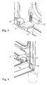
- an oven 10 comprises a cooking chamber 11 and a door 12 suitable for closing the chamber 11.
- the door 12 consists of a perimeter framework comprising two lateral uprights 13 and an upper cross member 14 which retain, inside, three sheet-like elements (typically glass) 15, 16 and 17 respectively. They are opposite, spaced and parallel to one another, so that between the uprights 13, the cross member 14 and the three glass panels 15, 16 and 17, a thermally insulating cavity is formed.
- three sheet-like elements typically glass
- the first glass 15 is the outer one with respect to the chamber 11
- the second glass 16 is the intermediate one
- the third glass 17 is the inner one, i.e. the one facing the chamber 11.
- the perimeter framework of the door 12 is combined with the chamber 11 by means of a pair of hinges 18 and relative springs (not shown), suitable for allowing opening and closing of the door.
- the hinges 18 are fixed laterally to and below the uprights 13.
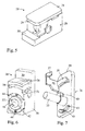
- the door 12 of the oven furthermore comprises, in the vicinity of the hinges 18, two blocks 19, composed of a fixed part 20, integral with the uprights 13, and a movable part 21.
- the uprights 13 comprise a U-shaped bar inside which, at their lower end, the hinges 18 are fixed.
- the two blocks 19 are fixed laterally to the U-shaped bar, at their lower end, in the inner part of the door 12, beside the hinges 18.
- the fixed part 20 has a foot 30, which extends externally and at the bottom on a short side of the fixed part 20.
- a portion 29 extends beyond the fixed part 20, on the side of the foot 30, and opposes it.
- the block 19 seen laterally has a substantially U-shaped form rotated by 90°.
- both the movable part 21 and the fixed part 20 substantially both have the form of a parallelepiped, with the fixed part 20 of larger dimensions (height) than the movable part 21, which rotates.
- the fixed part 20 comprises two holes.
- a first hole 31 is positioned crosswise in order to fix the block 19, by means of a screw or bolt, on the upright 13.
- a second hole 32 positioned vertically on the fixed part 20, opposite the foot 30, is provided in order to cooperate with a pin 33, positioned on the movable part 21. In this way the movable part 21 can rotate around the pin 33.
- the pin 33 is positioned substantially in the vicinity of a short side of the movable part 21, and laterally to a central axis of the movable part 21.
- a protrusion 43 in the form of an arc of a circle is positioned.
- the protrusion 43 runs in the circular slot 44, positioned around the hole 32, which acts as a guide during rotation of the movable part 21.
- the protrusion 43 comprises, in its central part, raised elements 45 which cooperate with grooves 46 positioned along a longitudinal central axis of the fixed part and temporarily block the movable part 21 in the open and closed position.
- a slot 34 which represents an arc of a circle is also provided on the fixed part 20. It is positioned in the vicinity of the foot 30 and therefore opposite the hole 32. It has a radius of curvature equal to the distance between this slot 34 and the centre of the hole 32.
- the slot 34 terminates on one side in a blind part while on the other it is accessible throughout its depth, which is equal to the height of the fixed part 20 minus the height of the foot 30.
- the movable part 21 at the level of the slot 34, has a protrusion 35 in the form of an arc of a circle.
- the protrusion 35 runs in the slot 34, which acts as a guide, during rotation of the movable part 21.
- a bar 36 which terminates in a chamfered foot 37 is connected perpendicular to said movable part.
- the foot 37 is fixed perpendicular to the bar 36, in a direction internal to the movable part 21.
- Said chamfered foot 37 cooperates with a chamfer 38 made in the fixed part 20 in the vicinity of the slot 34, so that when the movable part is re-closed, the foot 37 and the chamfer 38 interfere with one another, thus avoiding accidental opening of the movable part 21.
- the block 19 is preferably made of plastic able to withstand the oven temperatures.
- the movable part 21 of the blocks 19, in the closed position has the portion 29 which develops externally to the fixed central part 20 and opposes at least partially the foot 30.
- the block 19 with the outer part 29 of the movable part 21 retains the outer glass in position and the foot 30 sustains the inner glass.
- the movable part 21 can rotate 180° on the pin 33 to reach an open position.
- Face 22 indicates for example the border of the chamber 11 which abuts against the door 12.
- the glass panels are no longer retained by the block 19 in the closed position, they can be removed and cleaned, but the door 12 cannot re-close.
- the movable part 21 is rotated again by 180°; the door can then be closed and the glass panels are retained in position by the portion 29 of the movable part 21 which extends beyond the fixed part 20.
Abstract
Description
- The present inventions refers to a kitchen oven door.
- Various types of kitchen oven doors are known, and in general they are all provided with one or more glass panels (or other materials suitable for high temperatures) for insulation of the glass combined with the door and in contact with the external environment.
- Each glass panel is separated and spaced from the one nearby by means of appropriate spacers positioned laterally to the glass panels.
- This is due essentially to the need to prevent dispersion of the heat to the outside and to avoid users accidentally sustaining burns when they come into contact with the outer glass.
- During use of the oven, the glass can become dirty and may have to be cleaned. For easier and more effective cleaning of the glass panels, it is advisable to remove them from the door.
- Since the hinge springs are sized to keep the door balanced when it is completely equipped, if the user removes one or more of the glass panels from the door, with the door mounted on the oven, the force exerted by the springs, since it is no longer compensated for by the weight of the glass, would cause the door to shut violently with the risk of injury.
- The user is therefore obliged to remove the door from the oven in order to disassemble the glass panels for cleaning.
- The object of the present invention is to provide a kitchen oven door able to eliminate or at least drastically reduce the drawbacks of the known art.
- A further object of the present invention is to make available an oven door which allows the glass panel(s) of the door to be removed in a simple manner.
- A further object of the present invention is to obtain a door which is of simple construction and has a competitive production cost.
- In accordance with the present invention, said objects and others are achieved by a kitchen oven door comprising a perimeter framework; at least two sheet-like elements supported by said framework and removable from it; characterised in that it comprises at least one structural element having a first closed position and a second open position; said structural element in said first closed position retains one of said at least two sheet-like elements; said structural element in said second open position releases one of said at least two sheet-like elements and opposes the closure of said door.
- Further characteristics of the invention are described in the dependent claims.
- The present solution integrates the function of releasing the inner glass panels with the function of preventing rotation of the unbalanced door.
- When the movable part rotates, it rests on the face of the oven, preventing the door from closing even if the weight is reduced due to removal of the glass.
- The characteristics and advantages of the present invention will be evident from the following detailed description of a practical embodiment thereof, illustrated by way of non-limiting example in the accompanying drawings, in which:
-
figure 1 shows an oven, seen in perspective, according to the present invention; -
figure 2 shows an oven door, seen in perspective, according to the present invention; -
figure 3 shows a portion of an oven with a catch of the door in the closed position, according to the present invention; -
figure 4 shows a portion of an oven with a catch of the door in the open position, according to the present invention; -
figure 5 shows a catch of the door seen in perspective in the closed position, according to the present invention; -
figure 6 shows a fixed portion of a catch of the door, according to the present invention; -
figure 7 shows a movable portion of a catch of the door, according to the present invention. - Referring to the attached figures, an
oven 10, according to the present invention, comprises acooking chamber 11 and adoor 12 suitable for closing thechamber 11. - The
door 12 consists of a perimeter framework comprising twolateral uprights 13 and anupper cross member 14 which retain, inside, three sheet-like elements (typically glass) 15, 16 and 17 respectively. They are opposite, spaced and parallel to one another, so that between theuprights 13, thecross member 14 and the threeglass panels - In particular, the
first glass 15 is the outer one with respect to thechamber 11, thesecond glass 16 is the intermediate one and thethird glass 17 is the inner one, i.e. the one facing thechamber 11. - In the embodiment example described here, there are three glass panels but they can be of any number.
- The perimeter framework of the
door 12 is combined with thechamber 11 by means of a pair ofhinges 18 and relative springs (not shown), suitable for allowing opening and closing of the door. - The
hinges 18 are fixed laterally to and below theuprights 13. - The
door 12 of the oven furthermore comprises, in the vicinity of thehinges 18, twoblocks 19, composed of afixed part 20, integral with theuprights 13, and amovable part 21. - The
uprights 13 comprise a U-shaped bar inside which, at their lower end, thehinges 18 are fixed. - The two
blocks 19 are fixed laterally to the U-shaped bar, at their lower end, in the inner part of thedoor 12, beside thehinges 18. - The
fixed part 20 has afoot 30, which extends externally and at the bottom on a short side of thefixed part 20. - On a short side of the
movable part 21, aportion 29 extends beyond thefixed part 20, on the side of thefoot 30, and opposes it. Theblock 19 seen laterally has a substantially U-shaped form rotated by 90°. - The
blocks 19, both themovable part 21 and the fixed part 20 (with the exception of the foot 30) substantially both have the form of a parallelepiped, with thefixed part 20 of larger dimensions (height) than themovable part 21, which rotates. - The
fixed part 20 comprises two holes. Afirst hole 31 is positioned crosswise in order to fix theblock 19, by means of a screw or bolt, on the upright 13. Asecond hole 32 positioned vertically on thefixed part 20, opposite thefoot 30, is provided in order to cooperate with apin 33, positioned on themovable part 21. In this way themovable part 21 can rotate around thepin 33. Thepin 33 is positioned substantially in the vicinity of a short side of themovable part 21, and laterally to a central axis of themovable part 21. - Beside the
pin 33, on the surface of themovable part 21 which faces thefixed part 20, there is aprotrusion 40 which fits into aslot 41 beside thehole 32 of thefixed part 20, which during the movement of themovable part 21 is below the undercut 42 positioned around thehole 32. - On a circumference coaxial with that of the
pin 33, aprotrusion 43 in the form of an arc of a circle is positioned. Theprotrusion 43 runs in thecircular slot 44, positioned around thehole 32, which acts as a guide during rotation of themovable part 21. Theprotrusion 43 comprises, in its central part, raisedelements 45 which cooperate withgrooves 46 positioned along a longitudinal central axis of the fixed part and temporarily block themovable part 21 in the open and closed position. - A
slot 34 which represents an arc of a circle is also provided on thefixed part 20. It is positioned in the vicinity of thefoot 30 and therefore opposite thehole 32. It has a radius of curvature equal to the distance between thisslot 34 and the centre of thehole 32. - The
slot 34 terminates on one side in a blind part while on the other it is accessible throughout its depth, which is equal to the height of thefixed part 20 minus the height of thefoot 30. - The
movable part 21 , at the level of theslot 34, has aprotrusion 35 in the form of an arc of a circle. Theprotrusion 35 runs in theslot 34, which acts as a guide, during rotation of themovable part 21. - Laterally to the
movable part 21, at the height of theprofile 35, abar 36 which terminates in achamfered foot 37 is connected perpendicular to said movable part. Thefoot 37 is fixed perpendicular to thebar 36, in a direction internal to themovable part 21. - Said chamfered
foot 37 cooperates with achamfer 38 made in thefixed part 20 in the vicinity of theslot 34, so that when the movable part is re-closed, thefoot 37 and thechamfer 38 interfere with one another, thus avoiding accidental opening of themovable part 21. - The
block 19 is preferably made of plastic able to withstand the oven temperatures. - Any materials and dimensions can be used, however, according to requirements and the state of the art.
- Operation of the device according to the invention is evident from what is described and illustrated and, in particular, is substantially as follows.
- The
movable part 21 of theblocks 19, in the closed position, has theportion 29 which develops externally to the fixedcentral part 20 and opposes at least partially thefoot 30. In the closed position, theblock 19 with theouter part 29 of themovable part 21 retains the outer glass in position and thefoot 30 sustains the inner glass. - The
movable part 21 can rotate 180° on thepin 33 to reach an open position. - In this position, as the pin is out of line with respect to the main axis of the
fixed part 20, it is extended externally with respect to thefixed part 20, in an opposite position with respect to thefoot 30. - In this way its outer end rests on the
face 22 of the oven, preventing thedoor 12 from closing also when the weight is reduced due to removal of the glass panels. -
Face 22 indicates for example the border of thechamber 11 which abuts against thedoor 12. - Since the glass panels are no longer retained by the
block 19 in the closed position, they can be removed and cleaned, but thedoor 12 cannot re-close. - Once the glass panels have been cleaned, they are re-positioned and the
movable part 21 is rotated again by 180°; the door can then be closed and the glass panels are retained in position by theportion 29 of themovable part 21 which extends beyond the fixedpart 20. - The kitchen oven door thus conceived is subject to numerous modifications and variations, all falling within the scope of the inventive concept; furthermore all the details can be replaced by technically equivalent elements.
Claims (8)
- A kitchen oven door comprising a perimeter framework; at least two sheet-like elements supported by said framework and removable from it; characterised in that it comprises at least one structural element having a first closed position and a second open position; said structural element in said first closed position retains one of said at least two sheet-like elements; said structural element in said second open position releases one of said at least two sheet-like elements and opposes the closure of said door.
- The device as claimed in claim 1 characterised in that said structural element in said second open position opposes the face of said oven.
- The device as claimed in claim 1 characterised in that said at least two sheet-like elements are made of vitreous material.
- The device as claimed in claim 1, characterised in that said at least one structural element passes from said first closed position to said second open position by means of rotation.
- The device as claimed in claim 1 characterised in that said at least one structural element comprises a fixed part and a movable part, said movable part being rotating with respect to said fixed part.
- The device as claimed in claim 5 characterised in that said at least one structural element in said first closed position comprises said movable part which extends in a first direction with respect to said fixed part, retaining one of said at least two sheet-like elements.
- The device as claimed in claim 6 characterised in that said at least one structural element in said second open position comprises said movable part which extends in a second direction with respect to said fixed part so as to rest on the face of said oven.
- The device as claimed in claim 7 characterised in that said movable part rotates with respect to said fixed part, thus setting to said first closed position or said second position.
Priority Applications (1)
| Application Number | Priority Date | Filing Date | Title |
|---|---|---|---|
| PL10003845T PL2244017T3 (en) | 2009-04-22 | 2010-04-10 | Kitchen oven comprising kitchen oven door and structural element |
Applications Claiming Priority (1)
| Application Number | Priority Date | Filing Date | Title |
|---|---|---|---|
| IT000007U ITBG20090007U1 (en) | 2009-04-22 | 2009-04-22 | DOOR FOR KITCHEN OVENS |
Publications (3)
| Publication Number | Publication Date |
|---|---|
| EP2244017A2 true EP2244017A2 (en) | 2010-10-27 |
| EP2244017A3 EP2244017A3 (en) | 2016-12-21 |
| EP2244017B1 EP2244017B1 (en) | 2019-02-20 |
Family
ID=42561071
Family Applications (1)
| Application Number | Title | Priority Date | Filing Date |
|---|---|---|---|
| EP10003845.4A Active EP2244017B1 (en) | 2009-04-22 | 2010-04-10 | Kitchen oven comprising kitchen oven door and structural element |
Country Status (6)
| Country | Link |
|---|---|
| EP (1) | EP2244017B1 (en) |
| ES (1) | ES2717376T3 (en) |
| IT (1) | ITBG20090007U1 (en) |
| PL (1) | PL2244017T3 (en) |
| TR (1) | TR201904406T4 (en) |
| ZA (1) | ZA201002801B (en) |
Cited By (5)
| Publication number | Priority date | Publication date | Assignee | Title |
|---|---|---|---|---|
| WO2014207602A3 (en) * | 2013-06-28 | 2015-04-23 | Gorenje Gospodinjski Aparati, D.D. | Device for securing glass of a door for a household appliance |
| WO2022017797A1 (en) * | 2020-07-22 | 2022-01-27 | BSH Hausgeräte GmbH | Door and domestic cooking appliance |
| DE102020209248A1 (en) | 2020-07-22 | 2022-01-27 | BSH Hausgeräte GmbH | door and household cooking appliance |
| DE102020209247A1 (en) | 2020-07-22 | 2022-01-27 | BSH Hausgeräte GmbH | door and household cooking appliance |
| DE102020209249A1 (en) | 2020-07-22 | 2022-01-27 | BSH Hausgeräte GmbH | door and household cooking appliance |
Family Cites Families (3)
| Publication number | Priority date | Publication date | Assignee | Title |
|---|---|---|---|---|
| IT245078Y1 (en) * | 1998-07-21 | 2002-03-19 | Unox S N C Di Ing Franzolin En | DOOR PARTICULARLY FOR FOOD OVENS OR SIMILAR. |
| DE19923994A1 (en) * | 1999-05-26 | 2000-11-30 | Bsh Bosch Siemens Hausgeraete | Household appliance hinge device |
| DE102007040670B4 (en) * | 2007-08-27 | 2012-07-19 | Miele & Cie. Kg | Device for connecting glass panes of a household appliance door |
-
2009
- 2009-04-22 IT IT000007U patent/ITBG20090007U1/en unknown
-
2010
- 2010-04-10 PL PL10003845T patent/PL2244017T3/en unknown
- 2010-04-10 ES ES10003845T patent/ES2717376T3/en active Active
- 2010-04-10 EP EP10003845.4A patent/EP2244017B1/en active Active
- 2010-04-10 TR TR2019/04406T patent/TR201904406T4/en unknown
- 2010-04-21 ZA ZA2010/02801A patent/ZA201002801B/en unknown
Non-Patent Citations (1)
| Title |
|---|
| None |
Cited By (5)
| Publication number | Priority date | Publication date | Assignee | Title |
|---|---|---|---|---|
| WO2014207602A3 (en) * | 2013-06-28 | 2015-04-23 | Gorenje Gospodinjski Aparati, D.D. | Device for securing glass of a door for a household appliance |
| WO2022017797A1 (en) * | 2020-07-22 | 2022-01-27 | BSH Hausgeräte GmbH | Door and domestic cooking appliance |
| DE102020209248A1 (en) | 2020-07-22 | 2022-01-27 | BSH Hausgeräte GmbH | door and household cooking appliance |
| DE102020209247A1 (en) | 2020-07-22 | 2022-01-27 | BSH Hausgeräte GmbH | door and household cooking appliance |
| DE102020209249A1 (en) | 2020-07-22 | 2022-01-27 | BSH Hausgeräte GmbH | door and household cooking appliance |
Also Published As
| Publication number | Publication date |
|---|---|
| EP2244017A3 (en) | 2016-12-21 |
| ITBG20090007U1 (en) | 2010-10-23 |
| EP2244017B1 (en) | 2019-02-20 |
| ZA201002801B (en) | 2011-03-30 |
| PL2244017T3 (en) | 2019-07-31 |
| ES2717376T3 (en) | 2019-06-20 |
| TR201904406T4 (en) | 2019-04-22 |
Similar Documents
| Publication | Publication Date | Title |
|---|---|---|
| EP2244017A2 (en) | Kitchen oven door | |
| KR101227851B1 (en) | Door damper and home appliances with the same | |
| EP3542697A1 (en) | Door opening system for a domestic appliance | |
| EP2823124B1 (en) | Device and method for controlled door closing | |
| US3889654A (en) | Self-locking oven door hinge | |
| JP6249255B2 (en) | Closure system for through openings | |
| CN104188512A (en) | Electric kettle | |
| EP3511632B1 (en) | Swinging rack | |
| KR102096759B1 (en) | Air tightness and safety devices for doors | |
| KR101465043B1 (en) | Enforcement device for a press line cabinet door | |
| JP5385644B2 (en) | Raising and lowering window | |
| KR20110047867A (en) | Disconnection prevention for sash door | |
| EP1548217A2 (en) | Self-locking safety hinge, particularly for opening and closing an access panel | |
| ES2663675T3 (en) | Door for an appliance with a plate-like gripping part and an gripping-part opener, an appliance with such a door, as well as a procedure for opening an appliance door | |
| KR101337409B1 (en) | Hinged tilting device of door cover | |
| CN210592954U (en) | Mounting structure of box and turnover door | |
| JP2001061668A (en) | Support base elevation device of grill | |
| JP5695850B2 (en) | Door body open / close counting device | |
| EP3284888A1 (en) | Door hinge for an oven door | |
| CN104740658B (en) | Disinfection cabinet | |
| EP2957695A1 (en) | A cooking device having a top lid | |
| KR101507928B1 (en) | Castor module for preventing derailment | |
| KR101328686B1 (en) | Sliding type double windows | |
| KR970005754Y1 (en) | Tray for microwave oven | |
| CN213282590U (en) | Steam box door locking mechanism |
Legal Events
| Date | Code | Title | Description |
|---|---|---|---|
| PUAI | Public reference made under article 153(3) epc to a published international application that has entered the european phase |
Free format text: ORIGINAL CODE: 0009012 |
|
| AK | Designated contracting states |
Kind code of ref document: A2 Designated state(s): AT BE BG CH CY CZ DE DK EE ES FI FR GB GR HR HU IE IS IT LI LT LU LV MC MK MT NL NO PL PT RO SE SI SK SM TR |
|
| AX | Request for extension of the european patent |
Extension state: AL BA ME RS |
|
| RAP1 | Party data changed (applicant data changed or rights of an application transferred) |
Owner name: FRANKE TECHNOLOGY AND TRADEMARK LTD |
|
| PUAL | Search report despatched |
Free format text: ORIGINAL CODE: 0009013 |
|
| AK | Designated contracting states |
Kind code of ref document: A3 Designated state(s): AT BE BG CH CY CZ DE DK EE ES FI FR GB GR HR HU IE IS IT LI LT LU LV MC MK MT NL NO PL PT RO SE SI SK SM TR |
|
| AX | Request for extension of the european patent |
Extension state: AL BA ME RS |
|
| RIC1 | Information provided on ipc code assigned before grant |
Ipc: F24C 15/04 20060101AFI20161117BHEP |
|
| STAA | Information on the status of an ep patent application or granted ep patent |
Free format text: STATUS: REQUEST FOR EXAMINATION WAS MADE |
|
| 17P | Request for examination filed |
Effective date: 20170621 |
|
| RBV | Designated contracting states (corrected) |
Designated state(s): AT BE BG CH CY CZ DE DK EE ES FI FR GB GR HR HU IE IS IT LI LT LU LV MC MK MT NL NO PL PT RO SE SI SK SM TR |
|
| STAA | Information on the status of an ep patent application or granted ep patent |
Free format text: STATUS: EXAMINATION IS IN PROGRESS |
|
| 17Q | First examination report despatched |
Effective date: 20180305 |
|
| GRAP | Despatch of communication of intention to grant a patent |
Free format text: ORIGINAL CODE: EPIDOSNIGR1 |
|
| STAA | Information on the status of an ep patent application or granted ep patent |
Free format text: STATUS: GRANT OF PATENT IS INTENDED |
|
| INTG | Intention to grant announced |
Effective date: 20180921 |
|
| GRAS | Grant fee paid |
Free format text: ORIGINAL CODE: EPIDOSNIGR3 |
|
| GRAA | (expected) grant |
Free format text: ORIGINAL CODE: 0009210 |
|
| STAA | Information on the status of an ep patent application or granted ep patent |
Free format text: STATUS: THE PATENT HAS BEEN GRANTED |
|
| AK | Designated contracting states |
Kind code of ref document: B1 Designated state(s): AT BE BG CH CY CZ DE DK EE ES FI FR GB GR HR HU IE IS IT LI LT LU LV MC MK MT NL NO PL PT RO SE SI SK SM TR |
|
| REG | Reference to a national code |
Ref country code: GB Ref legal event code: FG4D |
|
| REG | Reference to a national code |
Ref country code: CH Ref legal event code: EP |
|
| REG | Reference to a national code |
Ref country code: DE Ref legal event code: R096 Ref document number: 602010057003 Country of ref document: DE |
|
| REG | Reference to a national code |
Ref country code: AT Ref legal event code: REF Ref document number: 1098696 Country of ref document: AT Kind code of ref document: T Effective date: 20190315 |
|
| REG | Reference to a national code |
Ref country code: IE Ref legal event code: FG4D |
|
| REG | Reference to a national code |
Ref country code: CH Ref legal event code: NV Representative=s name: VALIPAT S.A. GEVERS SA, CH |
|
| REG | Reference to a national code |
Ref country code: ES Ref legal event code: FG2A Ref document number: 2717376 Country of ref document: ES Kind code of ref document: T3 Effective date: 20190620 |
|
| REG | Reference to a national code |
Ref country code: LT Ref legal event code: MG4D |
|
| REG | Reference to a national code |
Ref country code: NL Ref legal event code: MP Effective date: 20190220 |
|
| PG25 | Lapsed in a contracting state [announced via postgrant information from national office to epo] |
Ref country code: LT Free format text: LAPSE BECAUSE OF FAILURE TO SUBMIT A TRANSLATION OF THE DESCRIPTION OR TO PAY THE FEE WITHIN THE PRESCRIBED TIME-LIMIT Effective date: 20190220 Ref country code: FI Free format text: LAPSE BECAUSE OF FAILURE TO SUBMIT A TRANSLATION OF THE DESCRIPTION OR TO PAY THE FEE WITHIN THE PRESCRIBED TIME-LIMIT Effective date: 20190220 Ref country code: NO Free format text: LAPSE BECAUSE OF FAILURE TO SUBMIT A TRANSLATION OF THE DESCRIPTION OR TO PAY THE FEE WITHIN THE PRESCRIBED TIME-LIMIT Effective date: 20190520 Ref country code: PT Free format text: LAPSE BECAUSE OF FAILURE TO SUBMIT A TRANSLATION OF THE DESCRIPTION OR TO PAY THE FEE WITHIN THE PRESCRIBED TIME-LIMIT Effective date: 20190620 Ref country code: SE Free format text: LAPSE BECAUSE OF FAILURE TO SUBMIT A TRANSLATION OF THE DESCRIPTION OR TO PAY THE FEE WITHIN THE PRESCRIBED TIME-LIMIT Effective date: 20190220 |
|
| PG25 | Lapsed in a contracting state [announced via postgrant information from national office to epo] |
Ref country code: HR Free format text: LAPSE BECAUSE OF FAILURE TO SUBMIT A TRANSLATION OF THE DESCRIPTION OR TO PAY THE FEE WITHIN THE PRESCRIBED TIME-LIMIT Effective date: 20190220 Ref country code: LV Free format text: LAPSE BECAUSE OF FAILURE TO SUBMIT A TRANSLATION OF THE DESCRIPTION OR TO PAY THE FEE WITHIN THE PRESCRIBED TIME-LIMIT Effective date: 20190220 Ref country code: IS Free format text: LAPSE BECAUSE OF FAILURE TO SUBMIT A TRANSLATION OF THE DESCRIPTION OR TO PAY THE FEE WITHIN THE PRESCRIBED TIME-LIMIT Effective date: 20190620 Ref country code: BG Free format text: LAPSE BECAUSE OF FAILURE TO SUBMIT A TRANSLATION OF THE DESCRIPTION OR TO PAY THE FEE WITHIN THE PRESCRIBED TIME-LIMIT Effective date: 20190520 Ref country code: NL Free format text: LAPSE BECAUSE OF FAILURE TO SUBMIT A TRANSLATION OF THE DESCRIPTION OR TO PAY THE FEE WITHIN THE PRESCRIBED TIME-LIMIT Effective date: 20190220 |
|
| REG | Reference to a national code |
Ref country code: AT Ref legal event code: MK05 Ref document number: 1098696 Country of ref document: AT Kind code of ref document: T Effective date: 20190220 |
|
| PG25 | Lapsed in a contracting state [announced via postgrant information from national office to epo] |
Ref country code: EE Free format text: LAPSE BECAUSE OF FAILURE TO SUBMIT A TRANSLATION OF THE DESCRIPTION OR TO PAY THE FEE WITHIN THE PRESCRIBED TIME-LIMIT Effective date: 20190220 Ref country code: SK Free format text: LAPSE BECAUSE OF FAILURE TO SUBMIT A TRANSLATION OF THE DESCRIPTION OR TO PAY THE FEE WITHIN THE PRESCRIBED TIME-LIMIT Effective date: 20190220 Ref country code: CZ Free format text: LAPSE BECAUSE OF FAILURE TO SUBMIT A TRANSLATION OF THE DESCRIPTION OR TO PAY THE FEE WITHIN THE PRESCRIBED TIME-LIMIT Effective date: 20190220 Ref country code: RO Free format text: LAPSE BECAUSE OF FAILURE TO SUBMIT A TRANSLATION OF THE DESCRIPTION OR TO PAY THE FEE WITHIN THE PRESCRIBED TIME-LIMIT Effective date: 20190220 Ref country code: DK Free format text: LAPSE BECAUSE OF FAILURE TO SUBMIT A TRANSLATION OF THE DESCRIPTION OR TO PAY THE FEE WITHIN THE PRESCRIBED TIME-LIMIT Effective date: 20190220 |
|
| REG | Reference to a national code |
Ref country code: DE Ref legal event code: R097 Ref document number: 602010057003 Country of ref document: DE |
|
| PG25 | Lapsed in a contracting state [announced via postgrant information from national office to epo] |
Ref country code: SM Free format text: LAPSE BECAUSE OF FAILURE TO SUBMIT A TRANSLATION OF THE DESCRIPTION OR TO PAY THE FEE WITHIN THE PRESCRIBED TIME-LIMIT Effective date: 20190220 |
|
| REG | Reference to a national code |
Ref country code: BE Ref legal event code: MM Effective date: 20190430 |
|
| PLBE | No opposition filed within time limit |
Free format text: ORIGINAL CODE: 0009261 |
|
| STAA | Information on the status of an ep patent application or granted ep patent |
Free format text: STATUS: NO OPPOSITION FILED WITHIN TIME LIMIT |
|
| PG25 | Lapsed in a contracting state [announced via postgrant information from national office to epo] |
Ref country code: AT Free format text: LAPSE BECAUSE OF FAILURE TO SUBMIT A TRANSLATION OF THE DESCRIPTION OR TO PAY THE FEE WITHIN THE PRESCRIBED TIME-LIMIT Effective date: 20190220 Ref country code: MC Free format text: LAPSE BECAUSE OF FAILURE TO SUBMIT A TRANSLATION OF THE DESCRIPTION OR TO PAY THE FEE WITHIN THE PRESCRIBED TIME-LIMIT Effective date: 20190220 Ref country code: LU Free format text: LAPSE BECAUSE OF NON-PAYMENT OF DUE FEES Effective date: 20190410 |
|
| 26N | No opposition filed |
Effective date: 20191121 |
|
| PG25 | Lapsed in a contracting state [announced via postgrant information from national office to epo] |
Ref country code: BE Free format text: LAPSE BECAUSE OF NON-PAYMENT OF DUE FEES Effective date: 20190430 Ref country code: SI Free format text: LAPSE BECAUSE OF FAILURE TO SUBMIT A TRANSLATION OF THE DESCRIPTION OR TO PAY THE FEE WITHIN THE PRESCRIBED TIME-LIMIT Effective date: 20190220 |
|
| PG25 | Lapsed in a contracting state [announced via postgrant information from national office to epo] |
Ref country code: IE Free format text: LAPSE BECAUSE OF NON-PAYMENT OF DUE FEES Effective date: 20190410 |
|
| PG25 | Lapsed in a contracting state [announced via postgrant information from national office to epo] |
Ref country code: CY Free format text: LAPSE BECAUSE OF FAILURE TO SUBMIT A TRANSLATION OF THE DESCRIPTION OR TO PAY THE FEE WITHIN THE PRESCRIBED TIME-LIMIT Effective date: 20190220 |
|
| PG25 | Lapsed in a contracting state [announced via postgrant information from national office to epo] |
Ref country code: GR Free format text: LAPSE BECAUSE OF FAILURE TO SUBMIT A TRANSLATION OF THE DESCRIPTION OR TO PAY THE FEE WITHIN THE PRESCRIBED TIME-LIMIT Effective date: 20190220 |
|
| PG25 | Lapsed in a contracting state [announced via postgrant information from national office to epo] |
Ref country code: HU Free format text: LAPSE BECAUSE OF FAILURE TO SUBMIT A TRANSLATION OF THE DESCRIPTION OR TO PAY THE FEE WITHIN THE PRESCRIBED TIME-LIMIT; INVALID AB INITIO Effective date: 20100410 Ref country code: MT Free format text: LAPSE BECAUSE OF FAILURE TO SUBMIT A TRANSLATION OF THE DESCRIPTION OR TO PAY THE FEE WITHIN THE PRESCRIBED TIME-LIMIT Effective date: 20190220 |
|
| PG25 | Lapsed in a contracting state [announced via postgrant information from national office to epo] |
Ref country code: MK Free format text: LAPSE BECAUSE OF FAILURE TO SUBMIT A TRANSLATION OF THE DESCRIPTION OR TO PAY THE FEE WITHIN THE PRESCRIBED TIME-LIMIT Effective date: 20190220 |
|
| PGFP | Annual fee paid to national office [announced via postgrant information from national office to epo] |
Ref country code: PL Payment date: 20230329 Year of fee payment: 14 |
|
| P01 | Opt-out of the competence of the unified patent court (upc) registered |
Effective date: 20230602 |
|
| PGFP | Annual fee paid to national office [announced via postgrant information from national office to epo] |
Ref country code: IT Payment date: 20230428 Year of fee payment: 14 Ref country code: FR Payment date: 20230417 Year of fee payment: 14 Ref country code: ES Payment date: 20230517 Year of fee payment: 14 Ref country code: DE Payment date: 20230412 Year of fee payment: 14 Ref country code: CH Payment date: 20230502 Year of fee payment: 14 |
|
| PGFP | Annual fee paid to national office [announced via postgrant information from national office to epo] |
Ref country code: TR Payment date: 20230412 Year of fee payment: 14 |
|
| PGFP | Annual fee paid to national office [announced via postgrant information from national office to epo] |
Ref country code: GB Payment date: 20230420 Year of fee payment: 14 |