EP2244009B1 - Wärmeableitende Anordnung eines LED-Lampenhalters - Google Patents
Wärmeableitende Anordnung eines LED-Lampenhalters Download PDFInfo
- Publication number
- EP2244009B1 EP2244009B1 EP09005730A EP09005730A EP2244009B1 EP 2244009 B1 EP2244009 B1 EP 2244009B1 EP 09005730 A EP09005730 A EP 09005730A EP 09005730 A EP09005730 A EP 09005730A EP 2244009 B1 EP2244009 B1 EP 2244009B1
- Authority
- EP
- European Patent Office
- Prior art keywords
- heat
- plate
- assembly
- lamp holder
- cover
- Prior art date
- Legal status (The legal status is an assumption and is not a legal conclusion. Google has not performed a legal analysis and makes no representation as to the accuracy of the status listed.)
- Not-in-force
Links
- 239000000758 substrate Substances 0.000 claims description 7
- ATJFFYVFTNAWJD-UHFFFAOYSA-N Tin Chemical compound [Sn] ATJFFYVFTNAWJD-UHFFFAOYSA-N 0.000 description 1
- 239000000853 adhesive Substances 0.000 description 1
- 230000001070 adhesive effect Effects 0.000 description 1
- 238000001816 cooling Methods 0.000 description 1
- 230000000694 effects Effects 0.000 description 1
- 238000002474 experimental method Methods 0.000 description 1
- 230000017525 heat dissipation Effects 0.000 description 1
- 238000011160 research Methods 0.000 description 1
- 239000002699 waste material Substances 0.000 description 1
Images

Classifications
-
- F—MECHANICAL ENGINEERING; LIGHTING; HEATING; WEAPONS; BLASTING
- F21—LIGHTING
- F21V—FUNCTIONAL FEATURES OR DETAILS OF LIGHTING DEVICES OR SYSTEMS THEREOF; STRUCTURAL COMBINATIONS OF LIGHTING DEVICES WITH OTHER ARTICLES, NOT OTHERWISE PROVIDED FOR
- F21V17/00—Fastening of component parts of lighting devices, e.g. shades, globes, refractors, reflectors, filters, screens, grids or protective cages
- F21V17/10—Fastening of component parts of lighting devices, e.g. shades, globes, refractors, reflectors, filters, screens, grids or protective cages characterised by specific fastening means or way of fastening
- F21V17/12—Fastening of component parts of lighting devices, e.g. shades, globes, refractors, reflectors, filters, screens, grids or protective cages characterised by specific fastening means or way of fastening by screwing
-
- F—MECHANICAL ENGINEERING; LIGHTING; HEATING; WEAPONS; BLASTING
- F21—LIGHTING
- F21V—FUNCTIONAL FEATURES OR DETAILS OF LIGHTING DEVICES OR SYSTEMS THEREOF; STRUCTURAL COMBINATIONS OF LIGHTING DEVICES WITH OTHER ARTICLES, NOT OTHERWISE PROVIDED FOR
- F21V29/00—Protecting lighting devices from thermal damage; Cooling or heating arrangements specially adapted for lighting devices or systems
- F21V29/50—Cooling arrangements
- F21V29/70—Cooling arrangements characterised by passive heat-dissipating elements, e.g. heat-sinks
- F21V29/71—Cooling arrangements characterised by passive heat-dissipating elements, e.g. heat-sinks using a combination of separate elements interconnected by heat-conducting means, e.g. with heat pipes or thermally conductive bars between separate heat-sink elements
- F21V29/717—Cooling arrangements characterised by passive heat-dissipating elements, e.g. heat-sinks using a combination of separate elements interconnected by heat-conducting means, e.g. with heat pipes or thermally conductive bars between separate heat-sink elements using split or remote units thermally interconnected, e.g. by thermally conductive bars or heat pipes
-
- F—MECHANICAL ENGINEERING; LIGHTING; HEATING; WEAPONS; BLASTING
- F21—LIGHTING
- F21V—FUNCTIONAL FEATURES OR DETAILS OF LIGHTING DEVICES OR SYSTEMS THEREOF; STRUCTURAL COMBINATIONS OF LIGHTING DEVICES WITH OTHER ARTICLES, NOT OTHERWISE PROVIDED FOR
- F21V29/00—Protecting lighting devices from thermal damage; Cooling or heating arrangements specially adapted for lighting devices or systems
- F21V29/50—Cooling arrangements
- F21V29/70—Cooling arrangements characterised by passive heat-dissipating elements, e.g. heat-sinks
- F21V29/74—Cooling arrangements characterised by passive heat-dissipating elements, e.g. heat-sinks with fins or blades
- F21V29/76—Cooling arrangements characterised by passive heat-dissipating elements, e.g. heat-sinks with fins or blades with essentially identical parallel planar fins or blades, e.g. with comb-like cross-section
- F21V29/763—Cooling arrangements characterised by passive heat-dissipating elements, e.g. heat-sinks with fins or blades with essentially identical parallel planar fins or blades, e.g. with comb-like cross-section the planes containing the fins or blades having the direction of the light emitting axis
-
- F—MECHANICAL ENGINEERING; LIGHTING; HEATING; WEAPONS; BLASTING
- F21—LIGHTING
- F21V—FUNCTIONAL FEATURES OR DETAILS OF LIGHTING DEVICES OR SYSTEMS THEREOF; STRUCTURAL COMBINATIONS OF LIGHTING DEVICES WITH OTHER ARTICLES, NOT OTHERWISE PROVIDED FOR
- F21V29/00—Protecting lighting devices from thermal damage; Cooling or heating arrangements specially adapted for lighting devices or systems
- F21V29/50—Cooling arrangements
- F21V29/70—Cooling arrangements characterised by passive heat-dissipating elements, e.g. heat-sinks
- F21V29/83—Cooling arrangements characterised by passive heat-dissipating elements, e.g. heat-sinks the elements having apertures, ducts or channels, e.g. heat radiation holes
-
- F—MECHANICAL ENGINEERING; LIGHTING; HEATING; WEAPONS; BLASTING
- F28—HEAT EXCHANGE IN GENERAL
- F28D—HEAT-EXCHANGE APPARATUS, NOT PROVIDED FOR IN ANOTHER SUBCLASS, IN WHICH THE HEAT-EXCHANGE MEDIA DO NOT COME INTO DIRECT CONTACT
- F28D15/00—Heat-exchange apparatus with the intermediate heat-transfer medium in closed tubes passing into or through the conduit walls ; Heat-exchange apparatus employing intermediate heat-transfer medium or bodies
- F28D15/02—Heat-exchange apparatus with the intermediate heat-transfer medium in closed tubes passing into or through the conduit walls ; Heat-exchange apparatus employing intermediate heat-transfer medium or bodies in which the medium condenses and evaporates, e.g. heat pipes
- F28D15/0275—Arrangements for coupling heat-pipes together or with other structures, e.g. with base blocks; Heat pipe cores
-
- F—MECHANICAL ENGINEERING; LIGHTING; HEATING; WEAPONS; BLASTING
- F21—LIGHTING
- F21V—FUNCTIONAL FEATURES OR DETAILS OF LIGHTING DEVICES OR SYSTEMS THEREOF; STRUCTURAL COMBINATIONS OF LIGHTING DEVICES WITH OTHER ARTICLES, NOT OTHERWISE PROVIDED FOR
- F21V15/00—Protecting lighting devices from damage
- F21V15/01—Housings, e.g. material or assembling of housing parts
-
- F—MECHANICAL ENGINEERING; LIGHTING; HEATING; WEAPONS; BLASTING
- F21—LIGHTING
- F21V—FUNCTIONAL FEATURES OR DETAILS OF LIGHTING DEVICES OR SYSTEMS THEREOF; STRUCTURAL COMBINATIONS OF LIGHTING DEVICES WITH OTHER ARTICLES, NOT OTHERWISE PROVIDED FOR
- F21V29/00—Protecting lighting devices from thermal damage; Cooling or heating arrangements specially adapted for lighting devices or systems
- F21V29/50—Cooling arrangements
- F21V29/51—Cooling arrangements using condensation or evaporation of a fluid, e.g. heat pipes
-
- F—MECHANICAL ENGINEERING; LIGHTING; HEATING; WEAPONS; BLASTING
- F21—LIGHTING
- F21Y—INDEXING SCHEME ASSOCIATED WITH SUBCLASSES F21K, F21L, F21S and F21V, RELATING TO THE FORM OR THE KIND OF THE LIGHT SOURCES OR OF THE COLOUR OF THE LIGHT EMITTED
- F21Y2115/00—Light-generating elements of semiconductor light sources
- F21Y2115/10—Light-emitting diodes [LED]
Definitions
- the present invention relates to a LED lamp, and in particular to a heat-dissipating assembly of a LED lamp holder.
- An assembly according to the preamble of claim 1 is disclosed in DE 10 2007 042 978 .
- LED Light-emitting diodes
- the LED since the LED is an electronic element, it has to be waterproof and dust-proof when being applied to an outdoor lamp. Further, the heat-dissipating performance of the LED has to be also taken into consideration.
- the current heat-dissipating assembly in a LED lamp holder continues using a heat sink or heat-dissipating device in a computer host.
- a heat-conducting plate is brought into contact with a heat source.
- heat pipes are connected to transmit the heat to the lamp cover or heat-dissipating fins, thereby cooling the heat source.
- the above-mentioned members have to be fixedly connected to each other with a superior heat-conducting effect, such as by means of tin paste or adhesive heat-conducting paste. Therefore, it is impossible to detach these members after being assembled together, which makes more difficult to replace the damaged components in the future. Since it is unable to replace the damaged components, the whole lamp holder should be replaced, which causes the waste in cost.
- the present Inventor proposes a reasonable and novel structure based on his delicate researches and expert experiments.
- the present invention is to provide an assembly of a LED lamp holder. Without affecting the contact between a heat-dissipating device and a heat source of a LED unit, a detachable assembly is provided, so that the components within the LED lamp holder can be replaced. Especially, after being detached, the contact between the heat-dissipating device and the heat source of the LED unit will not be affected.
- the present invention is to provide an assembly of a LED lamp holder, which includes a lamp cover and a heat-dissipating device provided in the lamp cover.
- An accommodating inlet is provided on the lamp cover.
- a LED unit is provided below the lamp cover.
- a cover plate covers the accommodating inlet.
- the heat-dissipating device comprises a heat-absorbing plate, a heat-dissipating plate and a heat pipe connected between the heat-absorbing plate and the heat-dissipating plate.
- the heat-absorbing plate is brought into contact with the LED unit, while the heat-dissipating plate is brought into contact with the cover plate.
- the cover plate is penetrated by a plurality of screw elements. Each of the screw elements is screwed to the heat-absorbing plate. The length of each screw element exactly makes the heat-absorbing plate to abut and contact the LED unit, and the respective screw elements can keep this state.
- the heat-dissipating device is assembled with the cover plate to form
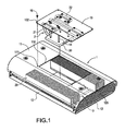
- Fig. 1 is an exploded perspective view of the present invention
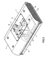
- Fig. 2 is an assembled view showing the internal structure of the present invention.
- the present invention provides an assembly of a LED lamp holder, which includes a lamp cover 1 and a heat-dissipating device 2 provided in the lamp cover 1.
- the lamp cover 1 is constituted of a base 10 and an upper cover 11.
- a LED unit 3 is disposed below the base 10.
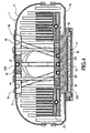
- the LED unit 3 comprises a circuit board 30 and a plurality of light-emitting diodes 31 provided on the circuit board 30, so that the light emitted by each of the light-emitting diodes 31 of the LED unit 3 can project toward the underside of the lamp cover 1 ( Fig. 4 ).
- Each of the front and rear sides of the base 10 is formed with an upright shielding plate 12.
- the slightly-curved upper cover 11 spans between the two shielding plates 12. Air holes 120 are provided on the shielding plate 12
- the heat-dissipating device 2 is provided in the lamp cover 1 and comprises a heat-absorbing plate 20, at least one heat pipe 21 and a heat-dissipating plate 22.
- the heat-absorbing plate 20 is brought into contact with the back surface of the LED unit 3 to facilitate the heat dissipation of the LED unit 3.
- a heat-conducting substrate 32 is adhered on the back surface of the LED unit 3.
- the bottom surface of the heat-conducting substrate 32 is provided with a trough 320 for allowing the LED unit 3 to be accommodated in the trough 320.
- the heat-absorbing plate 20 is provided with at least one groove 200 for allowing one end of the heat pipe 21 to be embedded therein.
- the groove 200 is preferably located on the bottom surface of the heat-absorbing plate 20, so that it can be adhered to the heat source of the LED unit 3 more closely.
- the heat-dissipating plate 22 is provided with at least one groove 220 for allowing the other end of the heat pipe 21 to be embedded therein.
- the groove 220 is preferably located on the top surface of the heat-dissipating plate 22, so that it can be further distant from the heat source of the LED unit 3.
- the upper cover 11 of the lamp cover 1 is provided with an accommodating inlet 110 that is positioned to correspond to the heat-dissipating device 2 for allowing the heat-dissipating device 2 to pass through.
- a cover plate 13 covers the accommodating inlet 110.
- the heat-dissipating plate 22 of the heat-dissipating device 2 is adhered to the underside of the cover plate 13.
- the cover plate 13 is assembled to the upside of the heat-dissipating device 2. Then, via the accommodating inlet 2, the heat-dissipating device 2 is assembled in the lamp cover 1, so that the underside of the heat-dissipating device 2 can be brought into contact with the heat source of the LED unit 3. At this time, a plurality of screw elements 14 such as bolts are used to penetrate the cover plate 13 to be screwed on the heat-absorbing plate 20.
- the cover plate 13 is provided with through-holes 130 for allowing the screw elements 14 to pass through. Further, the heat-absorbing plate 20 is provided with screw holes 201 for allowing the screw elements 14 to be screwed therein.
- the cover plate 13 is provided with through-holes 131 for allowing screws 15 to pass through.
- the through-holes 131 are positioned to correspond to the screw holes 221 on the heat-dissipating plate 22, so that the cover plate 13 and the heat-dissipating plate 22 can be brought into contact with each other via the screws.
- screws 16 may pass through the through-holes 132 to fasten the upper cover 11 to screw holes 111 near the periphery of the accommodating inlet 110, thereby completing the assembly.
- the length of the screw element 14 is preset to make the heat-absorbing plate 20 abut the back surface of the LED unit 3 or contact the top surface of the heat-conducting substrate 32.
- the heat-absorbing plate 20 of the heat-dissipating device 2 can be brought into contact with the heat source of the LED unit 3 surely.
- the present invention forms a detachable assembly, so that it is convenient to replace the components within this assembly in the future.
- the assembly of LED lamp holder of the present invention can be achieved.
- each of the screw elements 14 has an exact length to make the heat-absorbing plate 20 of the heat-dissipating device 2 abut and contact the LED unit 3. Further, via the respective screw elements 14, the above-mentioned state can be kept. Thus, the heat-dissipating device 2 is assembled with the cover plate 13 to form a detachable assembly. Even after detachment and re-assembly, the respective screw elements 14 can still maintain the contact between the heat-absorbing plate 20 and the LED unit 3.
- a layer of heat-conducting medium such as heat-conducting paste (not shown) can be applied between the heat-absorbing plate 20 and the back surface of the Led unit 3 (or the top surface of the heat-conducting substrate 32).
- the heat-dissipating device 2 is additionally provided with other heat-dissipating members 23 on the inner periphery of the lamp cover 1.
- the present invention already achieves the desired objects and overcomes the problems of prior art.
Landscapes
- Engineering & Computer Science (AREA)
- General Engineering & Computer Science (AREA)
- Life Sciences & Earth Sciences (AREA)
- Sustainable Development (AREA)
- Physics & Mathematics (AREA)
- Thermal Sciences (AREA)
- Mechanical Engineering (AREA)
- Arrangement Of Elements, Cooling, Sealing, Or The Like Of Lighting Devices (AREA)
- Non-Portable Lighting Devices Or Systems Thereof (AREA)
- Fastening Of Light Sources Or Lamp Holders (AREA)
Claims (9)
- Anordnung eines LED-Lampenhalters, umfassend:- eine Lampenabdeckung (1) mit einem Aufnahmezugang (110) an ihrer Oberseite und einer LED-Einheit an ihrer Unterseite, wobei eine Abdeckplatte (13) den Aufnahmezugang (110) bedeckt; und- eine wärmeableitende Vorrichtung (2), die innerhalb der Lampenabdeckung (1) bereitgestellt ist, und die eine wärmeabsorbierende Platte (20), eine wärmeableitende Platte (22) und eine Wärmeleitung (21), die zwischen die wärmeabsorbierende Platte (20) und die wärmeableitende Platte (22) angeschlossen ist, aufweist, wobei die wärmeabsorbierende Platte (20) mit der LED-Einheit (3) und die wärmeableitende Platte (22) mit der Abdeckplatte (13) in Kontakt ist;dadurch gekennzeichnet, dass
die Abdeckplatte (13) von mehreren Schraubenelementen (14) durchdrungen ist, wobei die Schraubenelemente (14) an der wärmeabsorbierenden Platte (20) angeschraubt sind, und wobei eine Länge eines jeden Schraubenelements (14) genau ausgelegt ist, um die wärmeabsorbierende Platte (20) an die LED-Einheit (3) zur Anlage zu bringen und sie mit dieser in Kontakt zu bringen, sowie diesen Zustand aufrecht zu erhalten. - Anordnung eines LED-Lampenhalters nach Anspruch 1, wobei die Lampenabdeckung (1) aus einer Basis (10) und einer oberen Abdeckung (11) gebildet ist, die LED-Einheit (3) unterhalb der Basis (10) angeordnet ist, und sich der Aufnahmezugang (110) an der oberen Abdeckung (11) befindet.
- Anordnung eines LED-Lampenhalters nach Anspruch 2, wobei jede der Vorder- und Rückseiten der Basis (10) mit einer aufrechten Abschirmplatte (12) ausgebildet ist, und die obere Abdeckung (11) gekrümmt ist und die zwei Abschirmplatten (12) der Vorder- und Rückseiten der Basis (10) umfasst.
- Anordnung eines LED-Lampenhalters nach Anspruch 3, wobei die beiden Abschirmplatten (12) mit Luftlöchern (120) versehen sind.
- Anordnung eines LED-Lampenhalters nach Anspruch 1, wobei die LED-Einheit (3) eine Leiterplatte (30) und mehrere lichtemittierende Dioden (31) auf der Leiterplatte (30) umfasst, eine Rückseite der Leiterplatte (30) mit einem wärmeleitenden Substrat (32) verklebt ist, und wobei die wärmeabsorbierende Platte (20) mit dem wärmeleitenden Substrat (32) verklebt und in Kontakt mit der LED-Einheit (3) ist.
- Anordnung eines LED-Lampenhalters nach Anspruch 5, wobei eine Unterseite des wärmeleitenden Substrats (32) mit einer Mulde (320) versehen ist, die zur Aufnahme der LED-Einheit (3) vorgesehen ist.
- Anordnung eines LED-Lampenhalters nach Anspruch 1, wobei die Abdeckplatte (13) mit Durchgangslöchern (130) versehen ist, die einen Durchgang entsprechender Schraubenelemente (14) erlauben, und die wärmeabsorbierende Platte (20) mit Schraubenlöchern (201) versehen ist, so dass die entsprechenden Schraubenelemente (14) darin eingeschraubt werden können.
- Anordnung eines LED-Lampenhalters nach Anspruch 7, wobei das Schraubenelement (14) ein Bolzen ist.
- Anordnung eines LED-Lampenhalters nach Anspruch 1, wobei das Schraubenelement (14) ein Bolzen ist.
Priority Applications (2)
| Application Number | Priority Date | Filing Date | Title |
|---|---|---|---|
| EP09005730A EP2244009B1 (de) | 2009-04-23 | 2009-04-23 | Wärmeableitende Anordnung eines LED-Lampenhalters |
| AT09005730T ATE520930T1 (de) | 2009-04-23 | 2009-04-23 | Wärmeableitende anordnung eines led-lampenhalters |
Applications Claiming Priority (1)
| Application Number | Priority Date | Filing Date | Title |
|---|---|---|---|
| EP09005730A EP2244009B1 (de) | 2009-04-23 | 2009-04-23 | Wärmeableitende Anordnung eines LED-Lampenhalters |
Publications (2)
| Publication Number | Publication Date |
|---|---|
| EP2244009A1 EP2244009A1 (de) | 2010-10-27 |
| EP2244009B1 true EP2244009B1 (de) | 2011-08-17 |
Family
ID=41112994
Family Applications (1)
| Application Number | Title | Priority Date | Filing Date |
|---|---|---|---|
| EP09005730A Not-in-force EP2244009B1 (de) | 2009-04-23 | 2009-04-23 | Wärmeableitende Anordnung eines LED-Lampenhalters |
Country Status (2)
| Country | Link |
|---|---|
| EP (1) | EP2244009B1 (de) |
| AT (1) | ATE520930T1 (de) |
Families Citing this family (2)
| Publication number | Priority date | Publication date | Assignee | Title |
|---|---|---|---|---|
| JP6301423B1 (ja) * | 2016-09-30 | 2018-03-28 | 株式会社テレビ東京 | 照明装置 |
| CN109990253B (zh) * | 2019-04-08 | 2021-03-26 | 广东力维电器有限公司 | 一种便于更换的led照明设备 |
Family Cites Families (4)
| Publication number | Priority date | Publication date | Assignee | Title |
|---|---|---|---|---|
| US20070081340A1 (en) * | 2005-10-07 | 2007-04-12 | Chung Huai-Ku | LED light source module with high efficiency heat dissipation |
| WO2007143875A2 (en) * | 2006-05-30 | 2007-12-21 | Jen-Shyan Chen | High-power and high heat-dissipating light emitting diode illuminating equipment |
| DE102007042978A1 (de) * | 2007-09-10 | 2009-03-12 | Osram Gesellschaft mit beschränkter Haftung | Lampe |
| CN101469819A (zh) * | 2007-12-27 | 2009-07-01 | 富准精密工业(深圳)有限公司 | 发光二极管灯具 |
-
2009
- 2009-04-23 AT AT09005730T patent/ATE520930T1/de not_active IP Right Cessation
- 2009-04-23 EP EP09005730A patent/EP2244009B1/de not_active Not-in-force
Also Published As
| Publication number | Publication date |
|---|---|
| ATE520930T1 (de) | 2011-09-15 |
| EP2244009A1 (de) | 2010-10-27 |
Similar Documents
| Publication | Publication Date | Title |
|---|---|---|
| US9241401B2 (en) | Solid state lighting device and method employing heat exchanger thermally coupled circuit board | |
| US7588355B1 (en) | LED lamp assembly | |
| US7654702B1 (en) | LED lamp | |
| US8267550B2 (en) | LED lamp for easy assembly and fixation | |
| US7677768B2 (en) | LED lamp having a convenient replacement structure | |
| US7726845B2 (en) | LED lamp | |
| EP2134569B1 (de) | Beleuchtungsanordnung mit einem wärmeabführgehäuse | |
| CN101566320B (zh) | 发光二极管灯具 | |
| US7648258B2 (en) | LED lamp with improved heat sink | |
| EP1785764A4 (de) | Wärmeabgebende einrichtung und display | |
| US20100246179A1 (en) | Led lamp | |
| US20090323331A1 (en) | Illumination device | |
| CA2549077A1 (en) | Light emitting diode (led) light bulbs | |
| CN101725947A (zh) | 发光二极管照明装置 | |
| CN102157671A (zh) | 发光二极管装置、照明设备及制造发光二极管装置的方法 | |
| US20100254140A1 (en) | Lamp holder of led streetlamp with heat-conducting and heat-dissipating capability | |
| EP2085681A2 (de) | LED-Beleuchtungsvorrichtung, LED-Lichtquellenmodul und LED-Trägerelement | |
| US20100265708A1 (en) | Heat-dissipating assembly of led lamp holder | |
| TW200719028A (en) | Backlight module | |
| US20110069500A1 (en) | Heat Dissipation Module For Bulb Type LED Lamp | |
| EP2244009B1 (de) | Wärmeableitende Anordnung eines LED-Lampenhalters | |
| US20090009996A1 (en) | Lighting Device | |
| CN202307882U (zh) | 发光装置及具备该发光装置的照明器具 | |
| US20080304270A1 (en) | Light emitting diode heat dissipation module | |
| US8182107B2 (en) | LED luminaire made with recycled materials |
Legal Events
| Date | Code | Title | Description |
|---|---|---|---|
| PUAI | Public reference made under article 153(3) epc to a published international application that has entered the european phase |
Free format text: ORIGINAL CODE: 0009012 |
|
| 17P | Request for examination filed |
Effective date: 20091215 |
|
| AK | Designated contracting states |
Kind code of ref document: A1 Designated state(s): AT BE BG CH CY CZ DE DK EE ES FI FR GB GR HR HU IE IS IT LI LT LU LV MC MK MT NL NO PL PT RO SE SI SK TR |
|
| AX | Request for extension of the european patent |
Extension state: AL BA RS |
|
| GRAP | Despatch of communication of intention to grant a patent |
Free format text: ORIGINAL CODE: EPIDOSNIGR1 |
|
| RIC1 | Information provided on ipc code assigned before grant |
Ipc: F21Y 101/02 20060101ALN20110209BHEP Ipc: F21V 29/00 20060101ALI20110209BHEP Ipc: F21V 17/12 20060101AFI20110209BHEP |
|
| RIN1 | Information on inventor provided before grant (corrected) |
Inventor name: HSU, KEN Inventor name: LIN, CHEN-HSIANG Inventor name: HUANG, CHIAO-LI Inventor name: WANG, HWAI-MING Inventor name: LIN, KUO-LEN Inventor name: CHENG, CHIH-HUNG |
|
| GRAS | Grant fee paid |
Free format text: ORIGINAL CODE: EPIDOSNIGR3 |
|
| GRAA | (expected) grant |
Free format text: ORIGINAL CODE: 0009210 |
|
| AK | Designated contracting states |
Kind code of ref document: B1 Designated state(s): AT BE BG CH CY CZ DE DK EE ES FI FR GB GR HR HU IE IS IT LI LT LU LV MC MK MT NL NO PL PT RO SE SI SK TR |
|
| REG | Reference to a national code |
Ref country code: GB Ref legal event code: FG4D |
|
| REG | Reference to a national code |
Ref country code: CH Ref legal event code: EP |
|
| REG | Reference to a national code |
Ref country code: IE Ref legal event code: FG4D |
|
| REG | Reference to a national code |
Ref country code: DE Ref legal event code: R096 Ref document number: 602009002127 Country of ref document: DE Effective date: 20111117 |
|
| REG | Reference to a national code |
Ref country code: NL Ref legal event code: T3 |
|
| LTIE | Lt: invalidation of european patent or patent extension |
Effective date: 20110817 |
|
| PG25 | Lapsed in a contracting state [announced via postgrant information from national office to epo] |
Ref country code: PT Free format text: LAPSE BECAUSE OF FAILURE TO SUBMIT A TRANSLATION OF THE DESCRIPTION OR TO PAY THE FEE WITHIN THE PRESCRIBED TIME-LIMIT Effective date: 20111219 Ref country code: NO Free format text: LAPSE BECAUSE OF FAILURE TO SUBMIT A TRANSLATION OF THE DESCRIPTION OR TO PAY THE FEE WITHIN THE PRESCRIBED TIME-LIMIT Effective date: 20111117 Ref country code: LT Free format text: LAPSE BECAUSE OF FAILURE TO SUBMIT A TRANSLATION OF THE DESCRIPTION OR TO PAY THE FEE WITHIN THE PRESCRIBED TIME-LIMIT Effective date: 20110817 Ref country code: IS Free format text: LAPSE BECAUSE OF FAILURE TO SUBMIT A TRANSLATION OF THE DESCRIPTION OR TO PAY THE FEE WITHIN THE PRESCRIBED TIME-LIMIT Effective date: 20111217 Ref country code: SE Free format text: LAPSE BECAUSE OF FAILURE TO SUBMIT A TRANSLATION OF THE DESCRIPTION OR TO PAY THE FEE WITHIN THE PRESCRIBED TIME-LIMIT Effective date: 20110817 Ref country code: FI Free format text: LAPSE BECAUSE OF FAILURE TO SUBMIT A TRANSLATION OF THE DESCRIPTION OR TO PAY THE FEE WITHIN THE PRESCRIBED TIME-LIMIT Effective date: 20110817 |
|
| REG | Reference to a national code |
Ref country code: AT Ref legal event code: MK05 Ref document number: 520930 Country of ref document: AT Kind code of ref document: T Effective date: 20110817 |
|
| PG25 | Lapsed in a contracting state [announced via postgrant information from national office to epo] |
Ref country code: LV Free format text: LAPSE BECAUSE OF FAILURE TO SUBMIT A TRANSLATION OF THE DESCRIPTION OR TO PAY THE FEE WITHIN THE PRESCRIBED TIME-LIMIT Effective date: 20110817 Ref country code: AT Free format text: LAPSE BECAUSE OF FAILURE TO SUBMIT A TRANSLATION OF THE DESCRIPTION OR TO PAY THE FEE WITHIN THE PRESCRIBED TIME-LIMIT Effective date: 20110817 Ref country code: SI Free format text: LAPSE BECAUSE OF FAILURE TO SUBMIT A TRANSLATION OF THE DESCRIPTION OR TO PAY THE FEE WITHIN THE PRESCRIBED TIME-LIMIT Effective date: 20110817 Ref country code: CY Free format text: LAPSE BECAUSE OF FAILURE TO SUBMIT A TRANSLATION OF THE DESCRIPTION OR TO PAY THE FEE WITHIN THE PRESCRIBED TIME-LIMIT Effective date: 20110817 Ref country code: GR Free format text: LAPSE BECAUSE OF FAILURE TO SUBMIT A TRANSLATION OF THE DESCRIPTION OR TO PAY THE FEE WITHIN THE PRESCRIBED TIME-LIMIT Effective date: 20111118 Ref country code: PL Free format text: LAPSE BECAUSE OF FAILURE TO SUBMIT A TRANSLATION OF THE DESCRIPTION OR TO PAY THE FEE WITHIN THE PRESCRIBED TIME-LIMIT Effective date: 20110817 |
|
| PG25 | Lapsed in a contracting state [announced via postgrant information from national office to epo] |
Ref country code: BE Free format text: LAPSE BECAUSE OF FAILURE TO SUBMIT A TRANSLATION OF THE DESCRIPTION OR TO PAY THE FEE WITHIN THE PRESCRIBED TIME-LIMIT Effective date: 20110817 |
|
| PG25 | Lapsed in a contracting state [announced via postgrant information from national office to epo] |
Ref country code: CZ Free format text: LAPSE BECAUSE OF FAILURE TO SUBMIT A TRANSLATION OF THE DESCRIPTION OR TO PAY THE FEE WITHIN THE PRESCRIBED TIME-LIMIT Effective date: 20110817 Ref country code: SK Free format text: LAPSE BECAUSE OF FAILURE TO SUBMIT A TRANSLATION OF THE DESCRIPTION OR TO PAY THE FEE WITHIN THE PRESCRIBED TIME-LIMIT Effective date: 20110817 |
|
| PG25 | Lapsed in a contracting state [announced via postgrant information from national office to epo] |
Ref country code: RO Free format text: LAPSE BECAUSE OF FAILURE TO SUBMIT A TRANSLATION OF THE DESCRIPTION OR TO PAY THE FEE WITHIN THE PRESCRIBED TIME-LIMIT Effective date: 20110817 Ref country code: IT Free format text: LAPSE BECAUSE OF FAILURE TO SUBMIT A TRANSLATION OF THE DESCRIPTION OR TO PAY THE FEE WITHIN THE PRESCRIBED TIME-LIMIT Effective date: 20110817 Ref country code: EE Free format text: LAPSE BECAUSE OF FAILURE TO SUBMIT A TRANSLATION OF THE DESCRIPTION OR TO PAY THE FEE WITHIN THE PRESCRIBED TIME-LIMIT Effective date: 20110817 |
|
| PLBE | No opposition filed within time limit |
Free format text: ORIGINAL CODE: 0009261 |
|
| STAA | Information on the status of an ep patent application or granted ep patent |
Free format text: STATUS: NO OPPOSITION FILED WITHIN TIME LIMIT |
|
| PG25 | Lapsed in a contracting state [announced via postgrant information from national office to epo] |
Ref country code: DK Free format text: LAPSE BECAUSE OF FAILURE TO SUBMIT A TRANSLATION OF THE DESCRIPTION OR TO PAY THE FEE WITHIN THE PRESCRIBED TIME-LIMIT Effective date: 20110817 |
|
| 26N | No opposition filed |
Effective date: 20120521 |
|
| PG25 | Lapsed in a contracting state [announced via postgrant information from national office to epo] |
Ref country code: HR Free format text: LAPSE BECAUSE OF FAILURE TO SUBMIT A TRANSLATION OF THE DESCRIPTION OR TO PAY THE FEE WITHIN THE PRESCRIBED TIME-LIMIT Effective date: 20120328 |
|
| PGFP | Annual fee paid to national office [announced via postgrant information from national office to epo] |
Ref country code: NL Payment date: 20120426 Year of fee payment: 4 Ref country code: DE Payment date: 20120430 Year of fee payment: 4 |
|
| PGFP | Annual fee paid to national office [announced via postgrant information from national office to epo] |
Ref country code: FR Payment date: 20120525 Year of fee payment: 4 |
|
| REG | Reference to a national code |
Ref country code: DE Ref legal event code: R097 Ref document number: 602009002127 Country of ref document: DE Effective date: 20120521 |
|
| PG25 | Lapsed in a contracting state [announced via postgrant information from national office to epo] |
Ref country code: MC Free format text: LAPSE BECAUSE OF NON-PAYMENT OF DUE FEES Effective date: 20120430 |
|
| REG | Reference to a national code |
Ref country code: IE Ref legal event code: MM4A |
|
| PG25 | Lapsed in a contracting state [announced via postgrant information from national office to epo] |
Ref country code: IE Free format text: LAPSE BECAUSE OF NON-PAYMENT OF DUE FEES Effective date: 20120423 |
|
| PG25 | Lapsed in a contracting state [announced via postgrant information from national office to epo] |
Ref country code: MK Free format text: LAPSE BECAUSE OF FAILURE TO SUBMIT A TRANSLATION OF THE DESCRIPTION OR TO PAY THE FEE WITHIN THE PRESCRIBED TIME-LIMIT Effective date: 20110817 |
|
| PG25 | Lapsed in a contracting state [announced via postgrant information from national office to epo] |
Ref country code: ES Free format text: LAPSE BECAUSE OF FAILURE TO SUBMIT A TRANSLATION OF THE DESCRIPTION OR TO PAY THE FEE WITHIN THE PRESCRIBED TIME-LIMIT Effective date: 20111128 |
|
| PG25 | Lapsed in a contracting state [announced via postgrant information from national office to epo] |
Ref country code: BG Free format text: LAPSE BECAUSE OF FAILURE TO SUBMIT A TRANSLATION OF THE DESCRIPTION OR TO PAY THE FEE WITHIN THE PRESCRIBED TIME-LIMIT Effective date: 20111117 |
|
| PG25 | Lapsed in a contracting state [announced via postgrant information from national office to epo] |
Ref country code: MT Free format text: LAPSE BECAUSE OF FAILURE TO SUBMIT A TRANSLATION OF THE DESCRIPTION OR TO PAY THE FEE WITHIN THE PRESCRIBED TIME-LIMIT Effective date: 20110817 |
|
| REG | Reference to a national code |
Ref country code: NL Ref legal event code: V1 Effective date: 20131101 |
|
| PG25 | Lapsed in a contracting state [announced via postgrant information from national office to epo] |
Ref country code: HR Free format text: LAPSE BECAUSE OF FAILURE TO SUBMIT A TRANSLATION OF THE DESCRIPTION OR TO PAY THE FEE WITHIN THE PRESCRIBED TIME-LIMIT Effective date: 20110817 |
|
| REG | Reference to a national code |
Ref country code: CH Ref legal event code: PL |
|
| GBPC | Gb: european patent ceased through non-payment of renewal fee |
Effective date: 20130423 |
|
| PG25 | Lapsed in a contracting state [announced via postgrant information from national office to epo] |
Ref country code: LI Free format text: LAPSE BECAUSE OF NON-PAYMENT OF DUE FEES Effective date: 20130430 Ref country code: DE Free format text: LAPSE BECAUSE OF NON-PAYMENT OF DUE FEES Effective date: 20131101 Ref country code: CH Free format text: LAPSE BECAUSE OF NON-PAYMENT OF DUE FEES Effective date: 20130430 Ref country code: GB Free format text: LAPSE BECAUSE OF NON-PAYMENT OF DUE FEES Effective date: 20130423 |
|
| REG | Reference to a national code |
Ref country code: FR Ref legal event code: ST Effective date: 20131231 |
|
| REG | Reference to a national code |
Ref country code: DE Ref legal event code: R119 Ref document number: 602009002127 Country of ref document: DE Effective date: 20131101 |
|
| PG25 | Lapsed in a contracting state [announced via postgrant information from national office to epo] |
Ref country code: NL Free format text: LAPSE BECAUSE OF NON-PAYMENT OF DUE FEES Effective date: 20131101 Ref country code: FR Free format text: LAPSE BECAUSE OF NON-PAYMENT OF DUE FEES Effective date: 20130430 |
|
| PG25 | Lapsed in a contracting state [announced via postgrant information from national office to epo] |
Ref country code: TR Free format text: LAPSE BECAUSE OF FAILURE TO SUBMIT A TRANSLATION OF THE DESCRIPTION OR TO PAY THE FEE WITHIN THE PRESCRIBED TIME-LIMIT Effective date: 20110817 |
|
| PG25 | Lapsed in a contracting state [announced via postgrant information from national office to epo] |
Ref country code: LU Free format text: LAPSE BECAUSE OF NON-PAYMENT OF DUE FEES Effective date: 20120423 |
|
| PG25 | Lapsed in a contracting state [announced via postgrant information from national office to epo] |
Ref country code: HU Free format text: LAPSE BECAUSE OF FAILURE TO SUBMIT A TRANSLATION OF THE DESCRIPTION OR TO PAY THE FEE WITHIN THE PRESCRIBED TIME-LIMIT Effective date: 20090423 |