EP2243996A2 - Wärmeableitungsvorrichtung und Beleuchtungsvorrichtung damit - Google Patents
Wärmeableitungsvorrichtung und Beleuchtungsvorrichtung damit Download PDFInfo
- Publication number
- EP2243996A2 EP2243996A2 EP09174582A EP09174582A EP2243996A2 EP 2243996 A2 EP2243996 A2 EP 2243996A2 EP 09174582 A EP09174582 A EP 09174582A EP 09174582 A EP09174582 A EP 09174582A EP 2243996 A2 EP2243996 A2 EP 2243996A2
- Authority
- EP
- European Patent Office
- Prior art keywords
- section
- main body
- solid
- state light
- illumination device
- Prior art date
- Legal status (The legal status is an assumption and is not a legal conclusion. Google has not performed a legal analysis and makes no representation as to the accuracy of the status listed.)
- Withdrawn
Links
Images


Classifications
-
- F—MECHANICAL ENGINEERING; LIGHTING; HEATING; WEAPONS; BLASTING
- F21—LIGHTING
- F21K—NON-ELECTRIC LIGHT SOURCES USING LUMINESCENCE; LIGHT SOURCES USING ELECTROCHEMILUMINESCENCE; LIGHT SOURCES USING CHARGES OF COMBUSTIBLE MATERIAL; LIGHT SOURCES USING SEMICONDUCTOR DEVICES AS LIGHT-GENERATING ELEMENTS; LIGHT SOURCES NOT OTHERWISE PROVIDED FOR
- F21K9/00—Light sources using semiconductor devices as light-generating elements, e.g. using light-emitting diodes [LED] or lasers
-
- F—MECHANICAL ENGINEERING; LIGHTING; HEATING; WEAPONS; BLASTING
- F21—LIGHTING
- F21V—FUNCTIONAL FEATURES OR DETAILS OF LIGHTING DEVICES OR SYSTEMS THEREOF; STRUCTURAL COMBINATIONS OF LIGHTING DEVICES WITH OTHER ARTICLES, NOT OTHERWISE PROVIDED FOR
- F21V29/00—Protecting lighting devices from thermal damage; Cooling or heating arrangements specially adapted for lighting devices or systems
- F21V29/50—Cooling arrangements
- F21V29/502—Cooling arrangements characterised by the adaptation for cooling of specific components
- F21V29/503—Cooling arrangements characterised by the adaptation for cooling of specific components of light sources
-
- F—MECHANICAL ENGINEERING; LIGHTING; HEATING; WEAPONS; BLASTING
- F21—LIGHTING
- F21V—FUNCTIONAL FEATURES OR DETAILS OF LIGHTING DEVICES OR SYSTEMS THEREOF; STRUCTURAL COMBINATIONS OF LIGHTING DEVICES WITH OTHER ARTICLES, NOT OTHERWISE PROVIDED FOR
- F21V29/00—Protecting lighting devices from thermal damage; Cooling or heating arrangements specially adapted for lighting devices or systems
- F21V29/50—Cooling arrangements
- F21V29/70—Cooling arrangements characterised by passive heat-dissipating elements, e.g. heat-sinks
- F21V29/74—Cooling arrangements characterised by passive heat-dissipating elements, e.g. heat-sinks with fins or blades
- F21V29/77—Cooling arrangements characterised by passive heat-dissipating elements, e.g. heat-sinks with fins or blades with essentially identical diverging planar fins or blades, e.g. with fan-like or star-like cross-section
- F21V29/777—Cooling arrangements characterised by passive heat-dissipating elements, e.g. heat-sinks with fins or blades with essentially identical diverging planar fins or blades, e.g. with fan-like or star-like cross-section the planes containing the fins or blades having directions perpendicular to the light emitting axis
-
- F—MECHANICAL ENGINEERING; LIGHTING; HEATING; WEAPONS; BLASTING
- F21—LIGHTING
- F21V—FUNCTIONAL FEATURES OR DETAILS OF LIGHTING DEVICES OR SYSTEMS THEREOF; STRUCTURAL COMBINATIONS OF LIGHTING DEVICES WITH OTHER ARTICLES, NOT OTHERWISE PROVIDED FOR
- F21V29/00—Protecting lighting devices from thermal damage; Cooling or heating arrangements specially adapted for lighting devices or systems
- F21V29/50—Cooling arrangements
- F21V29/70—Cooling arrangements characterised by passive heat-dissipating elements, e.g. heat-sinks
- F21V29/83—Cooling arrangements characterised by passive heat-dissipating elements, e.g. heat-sinks the elements having apertures, ducts or channels, e.g. heat radiation holes
-
- F—MECHANICAL ENGINEERING; LIGHTING; HEATING; WEAPONS; BLASTING
- F21—LIGHTING
- F21Y—INDEXING SCHEME ASSOCIATED WITH SUBCLASSES F21K, F21L, F21S and F21V, RELATING TO THE FORM OR THE KIND OF THE LIGHT SOURCES OR OF THE COLOUR OF THE LIGHT EMITTED
- F21Y2115/00—Light-generating elements of semiconductor light sources
- F21Y2115/10—Light-emitting diodes [LED]
Definitions
- the present invention relates generally to heat dissipation devices, and particularly to a heat dissipation device for efficiently dissipating heat from components such as illuminators.
- LEDs Light emitting diodes
- the stability of light emitted by LEDs is affected by heat generated by the LEDs.
- the temperature of an LED is too high, the light intensity of the LED may gradually attenuate, and the life span of the illumination device is liable to be shortened.
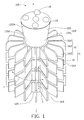
- FIG. 1 is an isometric view of a first embodiment of an illumination device utilizing a heat dissipation device.
- FIG. 2 is a side plan view of a second embodiment of an illumination device utilizing a heat dissipation device.
- FIG. 3 is an isometric view of a third embodiment of an illumination device utilizing a heat dissipation device.
- a heat dissipation device includes an elongated main body, a number of heat sinks, and a number of airflow channels.
- the main body has a central axis, and includes a first portion and a second portion.
- the second portion has an end distant from the first portion which is configured for supporting at least one item selected from the group consisting of a solid-state light source and a circuit board having a solid-state light source mounted thereon.
- the heat sinks are arranged around the first portion in sequence along the central axis of the main body, and spaced from one another.
- Each heat sink includes a number of fins extending out from the first portion radially.
- the airflow channel is defined between each two neighboring heat sinks.
- a first embodiment of an illumination device 100 includes a heat dissipation device 10 and at least one solid-state light source 18 mounted thereon.
- the heat dissipation device 10 dissipates heat from the at least one solid-state light source 18.
- the heat dissipation device 10 includes an elongated main body 12, and a plurality of heat sinks 16.
- the main body 12 has a central axis M, and includes a first portion 120 receiving the heat sinks 16.
- the first portion 120 has a first end 120A.
- Each heat sink 16 includes a cylindrical (or annular) sleeve 160, and a plurality of fins 162 extending out from the sleeve 160 radially. Preferably, the fins 162 are evenly spaced apart from each other around the sleeve 160.
- the heat sinks 16 are arranged around the first portion 120 in sequence along the central axis M of the main body 12, and are spaced from one another.
- the sleeve 160 of each heat sink 16 has an inner surface (not labeled) snugly contacting a peripheral surface of the first portion 120.
- the fins 162 thus surround not only the sleeve 160, but also the first portion 120 of the main body 12.
- the at least one solid-state light source 18 may be arranged on the first end 120A.
- the main body 12 advantageously further includes a second portion 122 extending up from the first end 120A of the first portion 120.
- the second portion 122 has a second end surface 122A, which is distant from the first portion 120.
- the second surface 122A may be larger than a corresponding horizontal dimension of the first end 120A.
- more than one solid-state light source 18 can be arranged on (or above) the second surface 122A.
- the first portion 120 is cylindrical
- the second portion 122 is frustoconical (a truncated circular cone).
- the second portion 122 includes a first end 12A adjoining (or connecting with) the first portion 120, and a second end 12B distant from the first portion 120.
- the second portion 122 tapers from top to bottom, and so the second end 12B is larger than the first end 12A.
- Five solid-state light sources 18 can be arranged on (or above) the second end surface 122A of the second end 12B.
- either or both of the first portion 120 and the second portion 122 may have other shapes.
- the first portion 120 may be prism-shaped, and the second portion 122 may be prismoid shaped.
- the solid-state light sources 18 can be LEDs, or other suitable kinds of light sources.
- the illumination device 100 may further include a circuit board 19, such as a printed circuit board.
- the circuit board 19 supports the solid-state light sources 18 thereon.
- the circuit board 19 can be disposed on the second end surface 122A to thereby contact the second portion 122 of the main body 12.
- the main body 12 and the heat sinks 16 may be made of metal with high thermal conductivity, such as copper, aluminum, copper-aluminum alloy, or other suitable metal or alloy.
- heat from the solid-state light sources 18 is transferred in sequence from the circuit board 19 to the second portion 122 and to the first portion 120.
- the heat is further transferred from the first portion 120 to the fins 162 through the sleeves 160.
- the fins 162 provide a large surface area in contact with ambient air. Thus a large amount of heat can be dissipated from the solid-state light sources 18.
- the illumination device 100 is that the heat sinks 16 are spaced from one another. Accordingly, a plurality of first airflow channels T are formed in a plurality of gaps 16A between each two neighboring heat sinks 16. The first airflow channels T surround the first portion 120 and allow air to flow therethrough. Thus the heat at the fins 162 can be efficiently dissipated.
- the solid-state light sources 18 are arranged at the second surface 122A distant from the first portion 120. If the heat accumulated at the heat sinks 16 is not dissipated promptly, heat from the solid-state light sources 18 can still be dissipated directly from the second portion 122.
- the heat sinks 16 can be arranged to have optimized heat dissipation performance.
- the number of fins 162 of each heat sink 16 may be the same as the number of fins 162 of each other heat sink 16.
- each fin 162 of each heat sink 16 may be aligned with a corresponding fin 162 of a neighboring heat sink 16 along a vertical direction parallel to the axis M of the main body 12.
- a plurality of second airflow channels S may be formed in gaps 16B between the fins 162.
- Each second airflow channel S extends along a series of the gaps 16B in a vertical direction parallel to the axis M of the main body 12.
- the second airflow channels S intersect with the first airflow channels T and allow air to flow therethrough.
- FIG. 2 is a side plan view of a second embodiment of an illumination device 200.
- the illumination device 200 includes a heat dissipation device 20, and a plurality of solid-state light sources 28.
- the heat dissipation device 20 is similar to the heat dissipation device 10 of the first embodiment.
- the heat dissipation device 20 includes an elongated main body 22, and a plurality of heat sinks 26.
- the elongated main body 22 includes a first portion 220 and a second portion 222.
- the second portion 222 includes a first section 22A extending up from the first portion 220, and a second section 22B distant from the first portion 220.
- the heat dissipation device 20 differs from the heat dissipation device 10, inter alia, in that each of the heat sinks 26 includes a plurality of fins 262 extending directly from the main body 22.
- the second portion 222 differs from the second portion 122 in structure.
- the first section 22A is circular frustoconical, and tapers downwardly.
- the second section 22B is generally circular frustoconical, and tapers upwardly.
- the second section 22B has a second end surface 222A and a plurality of planar side surfaces 222B. Each of the side surfaces 222B adjoins the second end surface 222A, and the side surfaces 222B surround the second end surface 222A. An obtuse angle 0 is defined between each side surface 222B and the second end surface 222A.
- the side surfaces 222B cooperate with the second end surface 222A to provide space for the solid-state light sources 28 to be arranged thereon or thereat.
- each of the side surfaces 222B supports a circuit board (not labeled) that has one solid-state light source 28, and the second end surface 222A supports a circuit board (not labeled) that has, for example, five solid-state light sources 28.
- a radiating range of the illumination device 200 is increased.
- FIG. 3 shows a third embodiment of an illumination device 300.
- the illumination device 300 includes a heat dissipation device 30, and a plurality of solid-state light sources 38.
- the heat dissipation device 30 is similar to the heat dissipation device 20 of the second embodiment.
- the heat dissipation device 30 includes an elongated main body 32, and a plurality of heat sinks 36.
- the elongated main body 32 includes a first portion 320 and a second portion 322.
- the second portion 322 includes a first section 32A and a second section 32B.
- the heat dissipation device 30 differs from the heat dissipation device 20, inter alia, in that the first section 32A is cylindrical, and the second section 32B is hexagonally frustoconical (i.e., prismoid).
- the second section 32B tapers upward. A diameter of a bottom of the second section 32B is larger than a diameter of the first section 32A.
- the second section 32B of the second portion 322 has a second end surface 322A and a plurality of planar side surfaces 322B.
- the side surfaces 322B cooperate with the second end surface 322A to provide space for the solid-state light sources 38 to be arranged thereon or thereat.
- each of the side surfaces 322B supports a circuit board (not labeled) that has one solid-state light source 38
- the second end surface 322A supports a circuit board (not labeled) that has, for example, one solid-state light source 38.
Landscapes
- Engineering & Computer Science (AREA)
- General Engineering & Computer Science (AREA)
- Physics & Mathematics (AREA)
- Microelectronics & Electronic Packaging (AREA)
- Optics & Photonics (AREA)
- Arrangement Of Elements, Cooling, Sealing, Or The Like Of Lighting Devices (AREA)
- Non-Portable Lighting Devices Or Systems Thereof (AREA)
- Led Device Packages (AREA)
Applications Claiming Priority (1)
| Application Number | Priority Date | Filing Date | Title |
|---|---|---|---|
| CN200910301794A CN101871584A (zh) | 2009-04-23 | 2009-04-23 | 照明装置 |
Publications (1)
| Publication Number | Publication Date |
|---|---|
| EP2243996A2 true EP2243996A2 (de) | 2010-10-27 |
Family
ID=42643857
Family Applications (1)
| Application Number | Title | Priority Date | Filing Date |
|---|---|---|---|
| EP09174582A Withdrawn EP2243996A2 (de) | 2009-04-23 | 2009-10-30 | Wärmeableitungsvorrichtung und Beleuchtungsvorrichtung damit |
Country Status (5)
| Country | Link |
|---|---|
| US (1) | US20100271823A1 (de) |
| EP (1) | EP2243996A2 (de) |
| JP (1) | JP2010257965A (de) |
| KR (1) | KR20100117023A (de) |
| CN (1) | CN101871584A (de) |
Cited By (1)
| Publication number | Priority date | Publication date | Assignee | Title |
|---|---|---|---|---|
| ITUD20110002A1 (it) * | 2011-01-14 | 2012-07-15 | Martini Spa | Dissipatore dinamico di calore |
Families Citing this family (26)
| Publication number | Priority date | Publication date | Assignee | Title |
|---|---|---|---|---|
| USD642298S1 (en) * | 2010-04-30 | 2011-07-26 | Acolyte Technologies Corporation | Lighting device |
| USD642299S1 (en) * | 2009-11-10 | 2011-07-26 | Acolyte Technologies Corporation | Lighting device |
| USD633232S1 (en) * | 2009-11-10 | 2011-02-22 | Acolyte Technologies Corporation | Lighting device |
| USD634456S1 (en) * | 2009-12-29 | 2011-03-15 | Jones Wayne H | Accent light |
| USD635708S1 (en) * | 2010-01-09 | 2011-04-05 | Foxconn Technology Co., Ltd. | LED lamp |
| USD643557S1 (en) * | 2010-02-12 | 2011-08-16 | Acolyte Technologies Corporation | Lighting device |
| USD633234S1 (en) * | 2010-02-12 | 2011-02-22 | Acolyte Technologies Corporation | Lighting device |
| USD647228S1 (en) * | 2010-04-30 | 2011-10-18 | Acolyte Technologies Corporation | Lighting device |
| USD690843S1 (en) | 2010-04-30 | 2013-10-01 | Acolyte Technologies Corporation | Lighting device |
| CN102003684B (zh) * | 2010-11-26 | 2012-05-23 | 北京化工大学 | 大功率led照明灯具散热结构 |
| BR112013027362A2 (pt) * | 2011-04-29 | 2017-01-17 | Koninkl Philips Nv | dispositivo e disposição de iluminação |
| USD690842S1 (en) | 2011-08-02 | 2013-10-01 | Acolyte Technologies Corporation | Lighting device |
| USD662882S1 (en) | 2011-08-02 | 2012-07-03 | Acolyte Technologies Corporation | Battery casing |
| USD690841S1 (en) | 2011-08-02 | 2013-10-01 | Acolyte Technologies Corporation | Lighting device |
| USD690840S1 (en) | 2011-08-02 | 2013-10-01 | Acolyte Technologies Corporation | Lighting device |
| USD686354S1 (en) | 2011-08-02 | 2013-07-16 | Acolyte Technologies Corporation | Lighting device |
| WO2013037138A1 (zh) * | 2011-09-16 | 2013-03-21 | Qin Biao | 固态照明灯 |
| CN103032721A (zh) * | 2011-10-05 | 2013-04-10 | 秦彪 | Led光引擎及led照明灯 |
| CN104676549A (zh) * | 2013-12-02 | 2015-06-03 | 苏州承源光电科技有限公司 | 一种led工矿灯散热器 |
| WO2016027913A1 (ko) * | 2014-08-19 | 2016-02-25 | 주식회사 케이아이그리드 | 엘이디 램프 |
| CN104595777A (zh) * | 2015-02-11 | 2015-05-06 | 宁波澎湃电子科技有限公司 | 一种灯具 |
| JP6781553B2 (ja) * | 2015-03-25 | 2020-11-04 | エルジー イノテック カンパニー リミテッド | ホルダーおよびこれを具備する照明装置 |
| US11134618B2 (en) * | 2016-08-30 | 2021-10-05 | Current Lighting Solutions, Llc | Luminaire including a heat dissipation structure |
| CN111520653B (zh) * | 2017-12-08 | 2022-03-11 | 嘉兴山蒲照明电器有限公司 | 一种led灯 |
| US11143394B2 (en) | 2018-02-08 | 2021-10-12 | Jiaxing Super Lighting Electric Appliance Co., Ltd | LED lamp |
| CN109340612B (zh) * | 2018-09-04 | 2021-01-05 | 东莞市闻誉实业有限公司 | 照明灯具 |
-
2009
- 2009-04-23 CN CN200910301794A patent/CN101871584A/zh active Pending
- 2009-10-30 EP EP09174582A patent/EP2243996A2/de not_active Withdrawn
-
2010
- 2010-02-04 US US12/699,981 patent/US20100271823A1/en not_active Abandoned
- 2010-04-15 KR KR1020100034669A patent/KR20100117023A/ko not_active Withdrawn
- 2010-04-16 JP JP2010094978A patent/JP2010257965A/ja active Pending
Cited By (1)
| Publication number | Priority date | Publication date | Assignee | Title |
|---|---|---|---|---|
| ITUD20110002A1 (it) * | 2011-01-14 | 2012-07-15 | Martini Spa | Dissipatore dinamico di calore |
Also Published As
| Publication number | Publication date |
|---|---|
| KR20100117023A (ko) | 2010-11-02 |
| JP2010257965A (ja) | 2010-11-11 |
| US20100271823A1 (en) | 2010-10-28 |
| CN101871584A (zh) | 2010-10-27 |
Similar Documents
| Publication | Publication Date | Title |
|---|---|---|
| EP2243996A2 (de) | Wärmeableitungsvorrichtung und Beleuchtungsvorrichtung damit | |
| US7874702B2 (en) | LED lamp with improved heat dissipating structure | |
| US7568817B2 (en) | LED lamp | |
| US7758214B2 (en) | LED lamp | |
| US7862210B2 (en) | LED lamp with heat sink assembly | |
| US7607803B2 (en) | LED lamp | |
| US7982225B2 (en) | Heat dissipation device for LED chips | |
| US20090021944A1 (en) | Led lamp | |
| US20090016072A1 (en) | Led lamp with a heat dissipation device | |
| US20090135594A1 (en) | Heat dissipation device used in led lamp | |
| US20100002438A1 (en) | Led lamp | |
| US8304971B2 (en) | LED light bulb with a multidirectional distribution and novel heat dissipating structure | |
| US20120098402A1 (en) | Led bulb | |
| US9714763B1 (en) | Lamp assembly and lamp device having the same | |
| KR101646190B1 (ko) | 채널 타입 방열 시스템을 포함하는 led 등기구 | |
| US20090154172A1 (en) | Led assembly with heat dissipation structure | |
| KR20090000151U (ko) | 엘이디조명기구용 방열기 | |
| US20090237929A1 (en) | Street illuminating device | |
| US20130163247A1 (en) | Lamp base and lamp having the same | |
| US20110181166A1 (en) | Led illuminating device | |
| JP2012064562A5 (de) | ||
| US20110255285A1 (en) | Illumination device with heat dissipation structures | |
| TWI398601B (zh) | 發光二極體燈具 | |
| KR101149795B1 (ko) | 엘이디 등기구 구조체 | |
| KR101142963B1 (ko) | 엘이디 조명 장치 |
Legal Events
| Date | Code | Title | Description |
|---|---|---|---|
| PUAI | Public reference made under article 153(3) epc to a published international application that has entered the european phase |
Free format text: ORIGINAL CODE: 0009012 |
|
| AK | Designated contracting states |
Kind code of ref document: A2 Designated state(s): AT BE BG CH CY CZ DE DK EE ES FI FR GB GR HR HU IE IS IT LI LT LU LV MC MK MT NL NO PL PT RO SE SI SK SM TR |
|
| AX | Request for extension of the european patent |
Extension state: AL BA RS |
|
| STAA | Information on the status of an ep patent application or granted ep patent |
Free format text: STATUS: THE APPLICATION IS DEEMED TO BE WITHDRAWN |
|
| 18D | Application deemed to be withdrawn |
Effective date: 20130503 |