EP2243922A2 - Spool-Gerätleitungssystem - Google Patents
Spool-Gerätleitungssystem Download PDFInfo
- Publication number
- EP2243922A2 EP2243922A2 EP10003895A EP10003895A EP2243922A2 EP 2243922 A2 EP2243922 A2 EP 2243922A2 EP 10003895 A EP10003895 A EP 10003895A EP 10003895 A EP10003895 A EP 10003895A EP 2243922 A2 EP2243922 A2 EP 2243922A2
- Authority
- EP
- European Patent Office
- Prior art keywords
- coiled tubing
- guide
- reel
- offshore
- guide system
- Prior art date
- Legal status (The legal status is an assumption and is not a legal conclusion. Google has not performed a legal analysis and makes no representation as to the accuracy of the status listed.)
- Withdrawn
Links
Images



Classifications
-
- E—FIXED CONSTRUCTIONS
- E21—EARTH OR ROCK DRILLING; MINING
- E21B—EARTH OR ROCK DRILLING; OBTAINING OIL, GAS, WATER, SOLUBLE OR MELTABLE MATERIALS OR A SLURRY OF MINERALS FROM WELLS
- E21B19/00—Handling rods, casings, tubes or the like outside the borehole, e.g. in the derrick; Apparatus for feeding the rods or cables
- E21B19/22—Handling reeled pipe or rod units, e.g. flexible drilling pipes
Definitions
- Oil producers use offshore platforms to support subsea oil wells.
- coiled tubing jobs are performed on the offshore platform.
- the coiled tubing is unspooled from a reel and injected through a rig floor via a coiled tubing injector hanging in a derrick.
- the coiled tubing reel must be placed in position so that a line of sight is maintained along the coiled tubing as it moves through a door in the rig floor.
- the line of sight requirement can create a variety of problems related to utilization of the offshore platform and completion of the coiled tubing job. For example, crane capability and lift radii restrictions often prevent placement of the heavy reel in an optimum position on the offshore platform. Additionally, placement of rig components, such as automated pipe handling systems and elevated catwalks, can be difficult without blocking the line of sight. Often, large deck areas of the offshore rig must be segregated with barriers during a coiled tubing job due to movement of the coiled tubing pipe overhead. As a result, rig operations and crane lifts are restricted. Because of the limitations on placement of the coiled tubing reel and other components, small radius goosenecks are sometimes necessary to direct the coiled tubing along a desired route. However, use of small radius goosenecks often detrimentally impacts the low cycle fatigue resistance of the coiled tubing.
- the present disclosure provides a system and methodology for facilitating coiled tubing operations in offshore environments.
- the system and methodology employ a spooled device disposed on a reel which is located on an offshore facility.
- a guide system is mounted on the offshore facility to guide the spooled device from the reel, along a desired path, and down through a floor of the offshore facility.
- the guide system enables the coiled tubing job to be conducted without requiring a line of sight along the coiled tubing as it is delivered down through the offshore facility.
- the present disclosure generally relates to a system and method for facilitating offshore well operations in which a spooled device is deployed from a surface facility.
- the technique enhances the efficient and safe use of a surface facility, e.g. an offshore platform/rig, a semi submersible rig, a monohull vessel, when deploying the spooled device to a subsea well or other location.
- the spooled device may comprise coiled tubing, wireline, slickline, or other spoolable device which is deployed from a reel.
- a guide system is mounted on the offshore facility to deliver the coiled tubing or other spooled device along a predetermined route in a manner which does not require "line of sight” control over the spooled device as it is delivered down through the offshore facility to a subsea wellhead or other subsea installation.
- the guide system is designed according to the size, shape, and components of the offshore facility.
- the guide system comprises a tubular guide, such as a pipe, e.g. steel pipe, through which the spooled device is routed.
- the tubular guide is designed with large radius curves to reduce or eliminate the fatigue otherwise experienced by certain spooled devices, such as coiled tubing.
- the guide system may be a continuous guide which fully encloses the route along which the coiled tubing is delivered from the coiled tubing reel to a location proximate a floor of the offshore facility. In other embodiments, however, the guide system may be intermittent such that the coiled tubing or other spooled device extends through open regions between tubular sections of the guide system.
- the guide system is permanently installed on the offshore facility.
- the guide system may be mounted during construction of the offshore facility, thus enabling the guide system to be fully integrated and fitted into the derrick and/or other components of the offshore facility.
- the guide system may incorporate additional components, such as mechanisms to grip and hold the coiled tubing (or other spooled device) at either end of the guide to increase rig up efficiency.
- the guide system also may incorporate swivels, extensions, flexible sections, lubricants, trumpet ends, roller guides, and other components designed to facilitate movement of the coiled tubing (or other spooled device) along the guide system during operation.
- the reel e.g. coiled tubing reel
- the reel may be placed in a variety of convenient locations, such as a lower deck location of an offshore platform.
- the guide system may be used to route the coiled tubing in a manner that does not interfere with pipe handling systems, elevated catwalks, and other components of the offshore facility.
- the guide system can free up large deck areas of the offshore facility by removing the need to create barrier regions which can restrict rig operations and crane lifts.
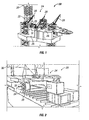
- an embodiment of an offshore system 20 is illustrated as having a guide system 22 incorporated into an offshore facility 24.
- the offshore facility 24 may comprise an offshore platform/rig, a semi submersible rig, a monohull vessel, or other offshore facility; however Figure 1 illustrates an example of an offshore platform/rig.
- the offshore facility 24 comprises a plurality of decks 26 located at different levels to enclose components or to provide surface area for a variety of components.
- the offshore facility 24 comprises a plurality of cranes 28 which are used to move components onto, off, and around the offshore facility.
- the offshore facility 24 comprises a derrick 30 which is used to deliver and retrieve components with respect to a subsea wellhead or other installation.
- at least a portion of the guide system 22 is mounted to the derrick 30.
- Guide system 22 simplifies the rig up of a spooled device, e.g. coiled tubing, on offshore installations 24, such as jack up offshore installations.
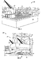
- a reel 32 may be positioned at a variety of convenient locations on the offshore facility 24.
- the reel 32 may be positioned at a convenient location 34 which is out of the way of many components used during various subsea well operations.
- reel 32 is located on a lower deck 36 of the plurality of decks 26.
- the lower deck 36 of this embodiment comprises a cantilevered pipedeck and is positioned beneath an upper deck/pedestal 38 on which derrick 30 is mounted.
- the reel 32 may be positioned in a variety of other convenient locations on the offshore facility 24.
- the reel 32 may be positioned so that coiled tubing 40 (or other spooled device) is spooled off the lower side of reel 32 rather than over the top of the reel.
- the coiled tubing 40 is delivered from reel 32 into a tubular guide 42, e.g. a pipe section, of guide system 22.
- guide system 22 may use tubular guide 42 in the form of one or more pipe sections which extend continuously or with interrupted segments from reel 32 through a bottom end of derrick 30 or to another desired exit location.
- the pipe sections of guide system 22 are constructed of suitably sized sections of pipe, e.g. steel pipe, with each section having a desired diameter and length.
- the tubular guide 42 has an outside diameter of approximately 5 inches, which is suitable for many types of coiled tubing and other spooled devices 40.
- the one or more pipe sections 42 also may be connected via flanges, e.g. ANSI 150 pound flanges, or other suitable connectors.
- guide system 22 may employ a series of elongated pipe sections 42 arranged along a designated path through which the spooled device, e.g. coiled tubing 40, travels from the reel 32 to a coiled tubing injector head. If the spooled device is not coiled tubing, e.g. slickline cable or wireline cable, then the tubing injector head is not necessary.
- the guide system 22 is formed from suitable materials, e.g. stainless steel, which prevent corrosion and ensure a low coefficient of friction as the spooled device 40 passes through the guide system 22. Internal surfaces of the pipe sections 42 may be prepared with low coefficient of friction coatings, lubricants, rollers, or other mechanisms to facilitate movement of the spooled device. To further facilitate consistent, easy movement of the coiled tubing or other spooled device 40, the guide system 22 may be permanently installed on the offshore facility during, for example, the original build phase. The predesigned, permanent installation enables guide system 22 to be fully integrated and fitted into the derrick 30 during construction.
- suitable materials e.g. stainless steel
- guide system 22 may employ pipe sections 42 with large radius curves 44 to reduce or eliminate fatigue experienced by the coiled tubing or other spooled device 40.
- Guide system 22 also may comprise a continuous, enclosed guide or an intermittent guide with straight, unconstrained runs between the intermittent pipe sections 42.
- pipe section 42 of guide system 22 extends from under the cantilever at a position beneath the upper deck or pedestal on which the derrick 30 is mounted. From this lower location of reel 32, the pipe section 42 curves upwardly and runs straight along a corner 46 of the derrick 30 until gently curving inwardly toward a central region of the derrick 30. The pipe section 42 then curves downwardly to a position which enables deployment of coiled tubing 40 through a floor opening of the offshore facility 24.
- the guide system 22 is lubricated.
- lubricant may be placed along the interior of the one or more pipe sections 42 by injecting suitable fluid/chemical products into the guide system.
- the guide system 22 and tubular guide 42 also may be designed to provide secondary fluid containment in the event of a rupture, e.g. a pinhole or pipe separation.
- the radii of the large radius curves 44 are selected according to the type and diameter of the spooled device 40.
- the large radius curves 44 are designed to accommodate coiled tubing of a desired diameter and material.
- a minimum radius of curvature may be calculated or otherwise obtained.
- a table is provided and lists coiled tubing of several outside diameters with corresponding equivalent radii of zero plastic deformation.
- Examples of the coiled tubing outside diameters and corresponding radii include: 1 inch OD - 5.08 m radius; 1.25 inch OD - 6.35 m radius; 1.5 inch OD -7.62 m radius; 1.75 inch OD - 8.89 m radius; 2 inch OD -10.16 m radius; 2.388 inch OD -12.13 m radius; and 2.875 inch OD - 14.61 m radius.
- large radius curves 44 may be designed to accommodate specific types or ranges of coiled tubing.
- the guide system 22 may incorporate spans larger than the minimum radius for all types of coiled tubing contemplated, e.g. larger than the minimum radius for 2.875 inch OD coiled tubing.
- the guide system 22 also may be designed to minimize the number of bends throughout the guide system.
- Various software models may be used to evaluate the effect of guide system bends in a given design relative to the anticipated fatigue life of the coiled tubing.
- guide system 22 also may comprise a variety of components which facilitate routing and control over the spooled device 40.
- guide system 22 comprises one or more swivel connections 48 at one or more points along tubular guide 42.
- the swivel connections 48 may be used to orient various features, e.g. an upper gooseneck, to ensure a desired routing of the spooled device 40.
- the swivel connections 48 may be used to move portions of guide system 22 temporarily out of the way and then back into position over a wellhead or well center located beneath an opening 50 in a floor 52 of the offshore facility 24.
- the swivel connections 48 also allow at least portions of the guide system 22 to be moved out of the way of rig operations when the guide system 22 is not being used.
- Guide system 22 also may comprise other components, such as a vertical extension section 54, e.g. a telescopic extension section, which may be used to provide vertical adjustability along the vertical dimension of derrick 30.
- Vertical extension section 54 allows the guide system 22 to accommodate different well control stacks, e.g. blowout preventer stacks, in derrick 30.
- the guide system 22 may further incorporate a variety of mechanisms to grip and hold the coiled tubing or other spooled device 40 at either end of the tubular guide 42 to increase rig up efficiency.
- guide system 22 provides the ability to run a cable winch and connector, e.g. a pipe stabbing connector, through the tubular guide 42.
- the connector is run from an upper portion of the tubular guide 42 to initially stab the coiled tubing 40 (or other spooled device). Once connected to the coiled tubing 40, the coiled tubing can be returned to the reel 32 in a controlled manner after the operation has been completed.
- the configuration and route of the guide system 22 may be rig specific to ensure the day-to-day operation of the rig is not obstructed.
- the entry point of the guide system 22 adjacent the reel 32 may be adjustable to accommodate various positioning of components on the offshore facility 24.
- the entry point of the guide system may be selected to accommodate different positions of a cantilever structure because such a structure can skid from side to side and/or from forward to aft depending on the location of equipment on the offshore facility 24.
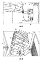
- FIG 6 an alternate position of guide system 22 is illustrated.
- the tubular guide 42 is attached to the corner of the derrick 30 and enters the workspace at a fingerboard height.
- the reel 32 may be positioned off the pipedeck, and the tubular guide 42 may incorporate trumpet ends 56 to avoid damaging the tubular guide pipe 42 during levelwind movement.
- the trumpet ends 56 enable an expanded angle of entry/exit of the coiled tubing or other spooled device 40 into and out of the tubular guide pipe 42.
- FIG 8 an embodiment is illustrated in which trumpet ends 56 are employed to facilitate movement of coiled tubing 40 from a gooseneck region within derrick 30 into a coiled tubing injector 58.
- tubular guide 42 is fitted in a manner similar to a standpipe along derrick 30.
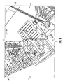
- Figure 9 provides an overhead view of derrick 30 which further illustrates opening 50 and corresponding doors 60 which may be used to selectively provide open access over a wellhead or well center 62.
- guide system 22 is constructed with an offshore facility 24 and is utilized to access a blowout preventer impact deck 64.
- guide system 22 employs tubular guide 42 to direct spooled device 40 from a position above a surface deck 66 to a position beneath the surface deck.
- Trumpet ends 56 may be used to facilitate routing of the spooled device to the injector head 58 located above the desired well center 62.
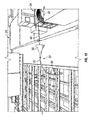
- a gooseneck 68 guides the spooled device 40 down through the injector head 58, as best illustrated in Figures 10 and 13 .
- the tubular guide 42 may comprise a flexible guide section 70, as best illustrated in Figures 11 and 12 .
- the flexible guide section or sections 70 may be employed to ensure component movement does not kink the tubular guide or the spooled device, e.g. coiled tubing.
- the flexible guide section 70 may be used to compensate for the movement of a levelwind.
- the flexible guide section 70 may be constructed from armored, braided high-pressure hose which is rubber lined and has a limited bend radius controlled by the size of the flexible segment.
- various mechanisms may be used to reduce friction and wear on the spooled device 40 as it moves through flexible guide section 70 and/or other sections of tubular guide 42.
- a variety of fluids and lubricants may be employed in the tubular guide.
- roller guides 72 and/or other friction reducing mechanisms can be employed along the route established by guide system 22.
- Guide system 22 may be incorporated into a variety of offshore facilities 24, including semi-submersible vessels, various platforms/rigs, and monohull vessels.
- the guide system 22 is useful in compensating for injector head movement when a heave compensation system is employed.
- the guide system 22 is designed to facilitate coiled tubing intervention on jack up rigs without running through the rig floor. This type of embodiment may be utilized when a coiled tubing operation is being conducted simultaneously while drilling.
- the guide system 22 enables routing of the spooled device from the location of reel 32 to the injector head 58 in a convenient manner which avoids the need for line of sight spooling.
- the route of the tubular guide 42 may be predetermined and selected to avoid restrictions, thereby obviating the need for roller guides or other features to bypass restrictions on the offshore rig/platform.
- the guide system 22 also may be used with wireline or slickline interventions on offshore installations and it may be used to eliminate the requirement for multiple sheaves during rig up preparation when performing at least one well service operation, such as, but not limited to, a coiled tubing operation, logging operation, slickline operation solid rod conveyance operation (for logging), stimulation operation, or similar well service operation, as will be appreciated by those skilled in the art.
- guide system 22 may be employed with a variety of offshore facilities having many types of components. The size, length and routing of the guide system may be adjusted according to the specifics characteristics of a given offshore facility. Additionally, components such as those discussed above may be incorporated into the guide system to facilitate movement and long-term operation of the spooled device in a given subsea application.
Landscapes
- Engineering & Computer Science (AREA)
- Geology (AREA)
- Life Sciences & Earth Sciences (AREA)
- Mining & Mineral Resources (AREA)
- Physics & Mathematics (AREA)
- Environmental & Geological Engineering (AREA)
- Fluid Mechanics (AREA)
- Mechanical Engineering (AREA)
- General Life Sciences & Earth Sciences (AREA)
- Geochemistry & Mineralogy (AREA)
- Earth Drilling (AREA)
- Guides For Winding Or Rewinding, Or Guides For Filamentary Materials (AREA)
- Storing, Repeated Paying-Out, And Re-Storing Of Elongated Articles (AREA)
Applications Claiming Priority (2)
| Application Number | Priority Date | Filing Date | Title |
|---|---|---|---|
| US21255609P | 2009-04-13 | 2009-04-13 | |
| US12/758,427 US20100263879A1 (en) | 2009-04-13 | 2010-04-12 | Spooled device guide system |
Publications (1)
| Publication Number | Publication Date |
|---|---|
| EP2243922A2 true EP2243922A2 (de) | 2010-10-27 |
Family
ID=42617465
Family Applications (1)
| Application Number | Title | Priority Date | Filing Date |
|---|---|---|---|
| EP10003895A Withdrawn EP2243922A2 (de) | 2009-04-13 | 2010-04-13 | Spool-Gerätleitungssystem |
Country Status (3)
| Country | Link |
|---|---|
| US (1) | US20100263879A1 (de) |
| EP (1) | EP2243922A2 (de) |
| SG (1) | SG166072A1 (de) |
Cited By (3)
| Publication number | Priority date | Publication date | Assignee | Title |
|---|---|---|---|---|
| CN103803394A (zh) * | 2014-02-20 | 2014-05-21 | 中煤第三建设(集团)有限责任公司 | 混凝土井塔外套装竖立大型箱型钢结构井架的起吊方法 |
| NL2014765A (en) * | 2015-05-04 | 2016-11-10 | Gustomsc Resources Bv | Drilling installation; Handling system, method for independent operations. |
| WO2016178576A3 (en) * | 2015-05-04 | 2017-03-16 | Gustomsc Resources B.V. | Drilling installation; handling system, method for independent operations |
Families Citing this family (2)
| Publication number | Priority date | Publication date | Assignee | Title |
|---|---|---|---|---|
| NO340587B1 (no) * | 2011-12-23 | 2017-05-15 | C6 Tech As | Fleksibel ledeanordning for brønnintervensjon |
| NL2016059B1 (en) * | 2016-01-05 | 2017-07-13 | Gustomsc Resources Bv | Drilling installation; Handling system, method for independent operations. |
Family Cites Families (5)
| Publication number | Priority date | Publication date | Assignee | Title |
|---|---|---|---|---|
| US6006839A (en) * | 1996-10-02 | 1999-12-28 | Stewart & Stevenson, Inc. | Pressurized flexible conduit injection system |
| US6386290B1 (en) * | 1999-01-19 | 2002-05-14 | Colin Stuart Headworth | System for accessing oil wells with compliant guide and coiled tubing |
| US7150324B2 (en) * | 2002-10-04 | 2006-12-19 | Halliburton Energy Services, Inc. | Method and apparatus for riserless drilling |
| CA2414764C (en) * | 2002-12-19 | 2007-11-13 | C-Tech Energy Services Inc. | Guide support for rig mounted continuous feed injection unit |
| GB0522971D0 (en) * | 2005-11-11 | 2005-12-21 | Qserv Ltd | Apparatus and method |
-
2010
- 2010-04-12 US US12/758,427 patent/US20100263879A1/en not_active Abandoned
- 2010-04-13 EP EP10003895A patent/EP2243922A2/de not_active Withdrawn
- 2010-04-15 SG SG201002649-0A patent/SG166072A1/en unknown
Non-Patent Citations (1)
| Title |
|---|
| None |
Cited By (9)
| Publication number | Priority date | Publication date | Assignee | Title |
|---|---|---|---|---|
| CN103803394A (zh) * | 2014-02-20 | 2014-05-21 | 中煤第三建设(集团)有限责任公司 | 混凝土井塔外套装竖立大型箱型钢结构井架的起吊方法 |
| CN103803394B (zh) * | 2014-02-20 | 2015-11-18 | 中煤第三建设(集团)有限责任公司 | 混凝土井塔外套装竖立大型箱型钢结构井架的起吊方法 |
| NL2014765A (en) * | 2015-05-04 | 2016-11-10 | Gustomsc Resources Bv | Drilling installation; Handling system, method for independent operations. |
| WO2016178576A3 (en) * | 2015-05-04 | 2017-03-16 | Gustomsc Resources B.V. | Drilling installation; handling system, method for independent operations |
| CN107709694A (zh) * | 2015-05-04 | 2018-02-16 | 格斯特Msc资源公司 | 钻井装置、搬运系统、用于独立作业的方法 |
| US10745983B2 (en) | 2015-05-04 | 2020-08-18 | Gustomsc B.V. | Drilling installation; handling system, method for independent operations |
| US11414938B2 (en) | 2015-05-04 | 2022-08-16 | Gustomsc B.V. | Drilling installation: handling system, method for independent operations |
| US11781384B2 (en) | 2015-05-04 | 2023-10-10 | Gustomsc B.V. | Drilling installation: handling system, method for independent operations |
| EP4219883A3 (de) * | 2015-05-04 | 2024-02-28 | GustoMSC B.V. | Bohranlage, handhabungssystem, verfahren für unabhängige operationen |
Also Published As
| Publication number | Publication date |
|---|---|
| US20100263879A1 (en) | 2010-10-21 |
| SG166072A1 (en) | 2010-11-29 |
Similar Documents
| Publication | Publication Date | Title |
|---|---|---|
| CA2501599C (en) | Method and apparatus for installing control lines in a well | |
| US5547314A (en) | Offshore system and method for storing and tripping a continuous length of jointed tubular conduit | |
| US7748464B2 (en) | Subsea well communications apparatus and method using variable tension large offset risers | |
| US6032744A (en) | Universal pipe and tubing injection apparatus and method | |
| US6161619A (en) | Riser system for sub-sea wells and method of operation | |
| US9458680B2 (en) | Drilling rig | |
| CN111491857B (zh) | 执行海底井筒相关活动的船和方法 | |
| US9677345B2 (en) | Well intervention apparatus and method | |
| US20050123358A1 (en) | Method and arrangement by a workover riser connection | |
| US20060137884A1 (en) | System, method and apparatus for securing control lines to a well pipe | |
| EP2243922A2 (de) | Spool-Gerätleitungssystem | |
| US20080185153A1 (en) | Subsea intervention with compliant guide | |
| US9045971B2 (en) | Subsea system | |
| NO347742B1 (en) | Offshore flexible line installation and removal | |
| US20110203803A1 (en) | Apparatus for subsea intervention | |
| US20050092497A1 (en) | Blow out preventer transfer platform | |
| US7530399B2 (en) | Delivery system for downhole use | |
| US20260049538A1 (en) | Vortex induced vibration mitigation method and system | |
| WO2019093904A1 (en) | Flexible tube well intervention | |
| WO2025211966A1 (en) | Vessel with tower column and coupling device for moving intervention equipment around column axis | |
| WO2026039740A1 (en) | Vortex induced vibration mitigation method and system | |
| NO20150306A1 (en) | Gravity Driven Coiled Tubing Intervention System | |
| EP3368723A2 (de) | Offshore-vorrichtung und verfahren |
Legal Events
| Date | Code | Title | Description |
|---|---|---|---|
| PUAI | Public reference made under article 153(3) epc to a published international application that has entered the european phase |
Free format text: ORIGINAL CODE: 0009012 |
|
| AK | Designated contracting states |
Kind code of ref document: A2 Designated state(s): AT BE BG CH CY CZ DE DK EE ES FI FR GB GR HR HU IE IS IT LI LT LU LV MC MK MT NL NO PL PT RO SE SI SK SM TR |
|
| AX | Request for extension of the european patent |
Extension state: AL BA ME RS |
|
| STAA | Information on the status of an ep patent application or granted ep patent |
Free format text: STATUS: THE APPLICATION IS DEEMED TO BE WITHDRAWN |
|
| 18D | Application deemed to be withdrawn |
Effective date: 20141101 |