EP2243721B1 - Dosing container - Google Patents
Dosing container Download PDFInfo
- Publication number
- EP2243721B1 EP2243721B1 EP10003187A EP10003187A EP2243721B1 EP 2243721 B1 EP2243721 B1 EP 2243721B1 EP 10003187 A EP10003187 A EP 10003187A EP 10003187 A EP10003187 A EP 10003187A EP 2243721 B1 EP2243721 B1 EP 2243721B1
- Authority
- EP
- European Patent Office
- Prior art keywords
- dosing
- metering
- chamber
- closure
- aperture
- Prior art date
- Legal status (The legal status is an assumption and is not a legal conclusion. Google has not performed a legal analysis and makes no representation as to the accuracy of the status listed.)
- Not-in-force
Links
Images


Classifications
-
- G—PHYSICS
- G01—MEASURING; TESTING
- G01F—MEASURING VOLUME, VOLUME FLOW, MASS FLOW OR LIQUID LEVEL; METERING BY VOLUME
- G01F11/00—Apparatus requiring external operation adapted at each repeated and identical operation to measure and separate a predetermined volume of fluid or fluent solid material from a supply or container, without regard to weight, and to deliver it
- G01F11/10—Apparatus requiring external operation adapted at each repeated and identical operation to measure and separate a predetermined volume of fluid or fluent solid material from a supply or container, without regard to weight, and to deliver it with measuring chambers moved during operation
- G01F11/26—Apparatus requiring external operation adapted at each repeated and identical operation to measure and separate a predetermined volume of fluid or fluent solid material from a supply or container, without regard to weight, and to deliver it with measuring chambers moved during operation wherein the measuring chamber is filled and emptied by tilting or inverting the supply vessel, e.g. bottle-emptying apparatus
- G01F11/261—Apparatus requiring external operation adapted at each repeated and identical operation to measure and separate a predetermined volume of fluid or fluent solid material from a supply or container, without regard to weight, and to deliver it with measuring chambers moved during operation wherein the measuring chamber is filled and emptied by tilting or inverting the supply vessel, e.g. bottle-emptying apparatus for fluent solid material
-
- G—PHYSICS
- G01—MEASURING; TESTING
- G01F—MEASURING VOLUME, VOLUME FLOW, MASS FLOW OR LIQUID LEVEL; METERING BY VOLUME
- G01F11/00—Apparatus requiring external operation adapted at each repeated and identical operation to measure and separate a predetermined volume of fluid or fluent solid material from a supply or container, without regard to weight, and to deliver it
- G01F11/10—Apparatus requiring external operation adapted at each repeated and identical operation to measure and separate a predetermined volume of fluid or fluent solid material from a supply or container, without regard to weight, and to deliver it with measuring chambers moved during operation
- G01F11/26—Apparatus requiring external operation adapted at each repeated and identical operation to measure and separate a predetermined volume of fluid or fluent solid material from a supply or container, without regard to weight, and to deliver it with measuring chambers moved during operation wherein the measuring chamber is filled and emptied by tilting or inverting the supply vessel, e.g. bottle-emptying apparatus
- G01F11/262—Apparatus requiring external operation adapted at each repeated and identical operation to measure and separate a predetermined volume of fluid or fluent solid material from a supply or container, without regard to weight, and to deliver it with measuring chambers moved during operation wherein the measuring chamber is filled and emptied by tilting or inverting the supply vessel, e.g. bottle-emptying apparatus for liquid or semi-liquid
- G01F11/263—Apparatus requiring external operation adapted at each repeated and identical operation to measure and separate a predetermined volume of fluid or fluent solid material from a supply or container, without regard to weight, and to deliver it with measuring chambers moved during operation wherein the measuring chamber is filled and emptied by tilting or inverting the supply vessel, e.g. bottle-emptying apparatus for liquid or semi-liquid with valves
-
- G—PHYSICS
- G01—MEASURING; TESTING
- G01F—MEASURING VOLUME, VOLUME FLOW, MASS FLOW OR LIQUID LEVEL; METERING BY VOLUME
- G01F15/00—Details of, or accessories for, apparatus of groups G01F1/00 - G01F13/00 insofar as such details or appliances are not adapted to particular types of such apparatus
- G01F15/14—Casings, e.g. of special material
Definitions
- the invention relates to a metering container, in particular a metering bottle, with at least one reservoir and at least one metering chamber, which are connected to one another via a metering, wherein the metering is provided with at least one in the raised position upper removal opening, which is arranged opposite a footprint of the metering.
- a dosing of the aforementioned type is for example from the EP 2 008 940 A2 known.
- This metering bottle for bulk material and granules or granular material comprises a reservoir and a metering chamber, which is connected to the reservoir via a metering or a metering, wherein the metering chamber is connected to a pouring channel.
- the metering chamber is arranged below the storage container so that the material flows from the storage container under the action of gravity into the metering container or into the metering channel.
- a differentiated dosage or even a return of once discharged into the metering material in the storage volume is not possible with such an arrangement.
- the material within the reservoir is always in direct contact with the material in the metering chamber.
- the flow of material into the metering chamber is avoided only at a certain tilt angle of the metering bottle. This also makes a differentiated dosage difficult.
- a differentiated dosage of the mostly granular or powdery material is required.
- a return of the material in the storage container is desirable.
- an unintended Nachströmen the material from the reservoir into the dosing or in the metering chamber should be prevented.
- the metering bottle described therein comprises a storage volume in a known manner or a storage container and a metering container, which is arranged spatially above the reservoir and is inserted into an upper opening of the bottle.
- the metering container comprises a receiving space for a product volume to be metered in and is closed off by a bottom and connected to a collecting chamber located above it by a connecting wall.
- This connecting wall has an upper opening which forms an access to the storage volume or reservoir.
- the connection opening or the dosing channel between the reservoir and the dosing is arranged so that the respective opening acts as an overflow in the upright position of the container. In this case, the amount of product entering the metering chamber and exceeding the amount that can accommodate the receiving space, falls back into the container when it is returned to its upright position.
- a dispenser according to the preamble of claim 1 is for example from the EP 0 492 534 A1 known.
- the dispenser further comprises a closure member which, in the closed state, closes both a passage opening from the storage chamber to the portioning chamber and the dispensing opening.
- a blocking part is formed, for blocking the passage opening from the storage chamber to the portioning chamber in the closed state, which locking part in the course of a Scheller movement of the closure part is displaceable through an opening in a ceiling of the portioning chamber.
- EP 1 041 368 A1 is a dosing for fixed dosages of liquids known, which also includes a storage volume and a metering chamber.
- the metering chamber is separated with a passage opening to the inside of the bottle. It communicates with a spout, which is guided in the bottle interior to the spout, such that with each tilting of the bottle from the upright position by 90 ° in a pouring only the contents of the dosing chamber is pourable.
- the invention is therefore based on the object to improve a Dosier therenis, in particular a metering bottle of the type mentioned in that a targeted return of material from the reservoir is possible, in particular a differentiated dosage should be possible.
- the object is achieved by a metering container according to claim 1.
- the obturator is designed as a slide which is connected to a rotatable closure part of the removal opening.
- the obturator is in a closed discharge opening in the position releasing the metering, so that in this case a differentiated filling of the metering is possible.
- the reservoir and the metering chamber are connected to each other via a metering in the direction of the metering chamber tapered.
- the inlet slope of the filling channel can be adjusted individually.
- An oblique formation of the metering or its opening in the metering chamber results in a uniform and fast filling of the dosing chamber.
- a tapered or conical metering channel results in optimal emptying of the reservoir.
- the metering channel extends at an angle to the level of contents of the erected container.
- the metering opening or the metering channel in the raised position of the metering container opens into the upper region of the metering chamber. This is particularly advantageous in the case of juxtaposed volumes of the dosing chamber on the one hand and the storage container on the other.
- the invention should be understood to mean that the metering opening or the metering channel can also open into another region of the metering chamber.
- the removal opening of the dosing can be provided with a multi-part closure, wherein a first closure member may be formed as a rotatable closure member and a second closure member as a pivotable cover closure member.
- the second closure part can, for example, be provided with a locking element which can only be locked and unlocked in a certain angular position of the first closure part.
- the closure of the removal opening comprises a pinhole, which is released in an angular position of the rotatable closure member, however, is closed in another angular position of the rotatable closure member.
- the dosing chamber and the storage container may be integrally connected, for example.
- the dosing can for example be made in one piece by extrusion blow molding.
- the different volumes of the dosing can be realized by wall-to-wall welding of Um chargedsplin.
- the metering container or the metering bottle according to the invention may be provided with a child safety device as well as with a tamper-evident closure.
- the metering container according to the invention is in a perspective view in FIG. 1 shown.
- This is in particular a dosing bottle 1 made of thermoplastic material produced by extrusion blow molding.
- the metering container according to the invention will be referred to below as a metering bottle 1, it is to be understood that this may be a canister, a barrel or similar container.
- the dosing bottle 1 is intended in particular for the reception of granular to powdery pourable contents, but this can be optimized for the absorption of liquids.
- the metering bottle 1 comprises a substantially level footprint 2, which limits in the illustrated embodiments exclusively a reservoir 3, which constitutes a substantial part of the volume of the metering bottle 1.
- a metering chamber 4 which forms a separate volume 3 relative to the reservoir.
- the metering chamber 4 and the reservoir 3 are connected to each other via a metering channel 5.
- this is provided with a removal opening 6 and a filling opening 7.
- the filling opening 7 is provided in the storage container 3, whereas the removal opening 6 closes the metering chamber 4.
- the filling opening 7 can be permanently closed with a closure cap 8.
- the closure cap 8 may have been welded to the outer surface of the metering bottle at the edge of the removal opening 6.
- the removal opening 6, however, is closed with a resealable lid closure 9.
- the lid closure 9 will be explained in detail below.
- the metering chamber 4 and the storage container 3 are connected to one another by a material web 10, wherein this material web 10 was obtained by wall-to-wall welding during extrusion blow molding of the metering bottle 1.
- the metering chamber 4 and the storage container 3 can communicate with one another only via the metering channel 5, which can be closed by means of a shut-off device.
- a removal of contents from the metering bottle 1 takes place first from the storage container 3 into the metering chamber 4 and from the metering chamber 4 through the removal opening 6.
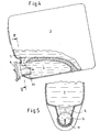
- FIG. 2 in which the metering bottle 1 is shown in longitudinal section.
- the metering chamber 4 does not extend to the footprint 2 of the metering bottle. This is in the described embodiment, however, mainly for design reasons of the case. In principle, it is possible that the metering chamber 4 and the storage container 3 form two mutually parallel volumes extending over the entire height of the metering bottle 1.
- the dosing extends at the top of the footprint 2 remote end of the metering bottle 1 in the reservoir 3 at an angle to Gregutapt in the metering chamber 4, in such a way that the entire volume of the metering chamber 4 can be acted upon with filling without that this runs back in upright container in the reservoir 3.
- the metering channel 5 is guided upwards starting from the storage container 3, the cross section of which tapers from the storage container 3 in the direction of the metering chamber 4.
- the metering channel 5 tapers both in height and in width, so that there is a total of approximately conical cross section of the metering.
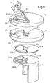
- the gate valve 11 as obturator is rotatably connected to a rotatable closure part 12 of the lid closure 9 (see FIG. 11 ).
- a closure flap 13 is hinged, which can be opened only in an angular position of the rotatable closure member 12, in that angular position in which the gate valve 11 closes the metering 5.
- the rotatable closure member 12 and the gate valve 11 are rotatably connected to each other via an integrally provided on the rotatable closure member 12 locking pin 14.
- the locking pin 14 is in the FIG. 10 not seen view.
- the closure flap is struck in the illustrated embodiment via a hinge 15 with a hinge pin 16 on the rotatable closure member 12, alternatively, the hinge 15 may be formed as a film hinge.
- the hinge 15 may be formed as a film hinge.
- rotatable closure member 12 and the gate valve 11 with respect to the removal opening 6 rotatably disposed closure member 17 is provided.
- a sealing washer 18 is arranged made of an elastic plastic.
- the gate valve 11 is integrally connected to a circular baffle plate 19 whose diameter corresponds to the diameter of the removal opening approximately and which is provided as a pinhole with two quarter-circular openings 20 a.
- Corresponding openings 20 b, 20 c and 20 d are respectively provided in the sealing washer 18 in the rotationally fixed closure member 17 and in the rotatable closure member 12.
- the rotationally fixed closure member 17, the sealing washer 18 and the baffle plate 19 are provided with a central, circular mounting hole 25 which is penetrated by the locking pin 14, which establishes a rotationally fixed connection between the closure parts 17 and 12.
- the rotationally fixed closure member 17 and the baffle plate 19 are held with the interposition of the sealing disc 18 against each other, the baffle plate 19 and the gate valve 11 integrally connected to it any rotation of the rotatable closure member 12 mitvollteil.
- the gate valve 11 In this angular position of the rotatable closure part 12, the gate valve 11 is in the in FIG. 2 shown position in which the dosing chamber 4 and the reservoir 3 do not communicate with each other.
- opening and closing the closure flap 13 is possible only in this angular position.
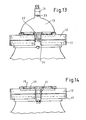
- the closure flap 13 is provided with a cross-sectionally C-shaped undercut securing bracket 21, whose cross-sectional profile is designed so that it can engage around the edge-side cross-sectional profile of the non-rotatable closure member 17 in a form-fitting manner.
- Both in the rotatable closure member 12 and in the rotationally fixed closure member 17 each have a peripheral rectangular recess 22 is provided. Both recesses 22 are approximately equal in width and in the in FIG. 10 shown angular position of the rotatable closure member 12 in alignment over one another, so that the closure bracket 21 can immerse in recessed 22 with pivoted flap 13. In this position, an unlocking pin 23 provided on the underside of the closure flap 13 presses on an opening provided in the non-rotatable closure part Spring tongue 24.
- the spring tongue fits in the in FIG. 10 shown angular position of the rotatable closure member 12 in the recess 22 a, so that the rotatable closure member 12 is locked in the respective angular position as long as the shutter 13 is in the open state.
- the unlocking pin presses the spring tongue 24 down so that it fits into the surface of the non-rotatable closure part 17 and allows a rotational movement of the rotatable closure part 12.
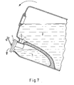
- the rotatable closure member 12 can be brought into an angular position, which allows opening of the closure flap 13. In this angular position of the metering channel 5 is closed by the gate valve, so that a removal from the metering chamber 4 is possible without the contents from the reservoir 3 flows into the metering chamber 4, as in FIG. 7 is shown.
- the gate valve 11 is formed by its shape and its operating principle as a shell slider.
- FIG. 8 An alternative embodiment of the metering chamber 4 and the metering 5 are in FIG. 8 shown.
- the metering channel is provided in the bottom region of the metering chamber 4.
- the gate valve 11 extends approximately over the entire height of the metering chamber and is provided with a lower closure body 25 in the form of a half-disc.
- FIG. 9 A further embodiment of the metering chamber and the arrangement of the metering is in FIG. 9 shown.
- the metering channel 5 ended approximately halfway up the metering chamber 4 in this.
- the gate valve 11 extends over about 2/3 of the height of the metering chamber. 4
- the unlocking pin 23 is laterally bevelled.
Description
Die Erfindung betrifft ein Dosierbehältnis, insbesondere eine Dosierflasche, mit wenigstens einem Vorratsbehälter und wenigstens einer Dosierkammer, die über eine Dosieröffnung miteinander verbunden sind, wobei der Dosierbehälter mit wenigstens einer in aufgestellter Lage oberen Entnahmeöffnung versehen ist, die gegenüberliegend einer Aufstellfläche des Dosierbehältnis angeordnet ist.The invention relates to a metering container, in particular a metering bottle, with at least one reservoir and at least one metering chamber, which are connected to one another via a metering, wherein the metering is provided with at least one in the raised position upper removal opening, which is arranged opposite a footprint of the metering.
Eine Dosierflasche der eingangsgenannten Art ist beispielsweise aus der
Bei bestimmten Insektiziden, Herbiziden, Pestiziden und andere Chemikalien, die in exakt dosierter Menge abgegeben werden müssen, ist eine differenzierte Dosierung des zumeist körnigen oder pulverartigen Materials erforderlich. Bei Überdosierung ist eine Rückführung des Materials in das Vorratsbehältnis wünschenswert. Auch soll ein unbeabsichtigtes Nachströmen vom Material aus dem Vorratsbehälter in das Dosierbehältnis bzw. in die Dosierkammer unterbunden werden.For certain insecticides, herbicides, pesticides and other chemicals that need to be dispensed in a precisely metered amount, a differentiated dosage of the mostly granular or powdery material is required. When overdosing a return of the material in the storage container is desirable. Also, an unintended Nachströmen the material from the reservoir into the dosing or in the metering chamber should be prevented.
Eine verbesserte Dosierflasche bzw. Mess- und Spendervorrichtung für granulat- oder pulverförmige Produkte ist beispielsweise aus der
Durch die räumliche Anordnung der Dosierkammer oberhalb des Vorratsbehälters ist allerdings eine differenzierte Dosierung mit der Dosierflasche nach der
Unter einer differenzierten Dosierung im Sinne der Erfindung ist die Einbringung unterschiedlicher vorgegebener Abgabemengen in die Dosierkammer zur Erzielung verschiedener Dosagen zu verstehen.Under a differentiated dosage in the context of the invention, the introduction of different predetermined discharge amounts in the dosing to achieve different dosages to understand.
Ein Spender nach Oberbegriff von Anspruch 1 ist beispielsweise aus der
Ein ähnliches Dosierbehältnis ist beispielsweise aus der
Aus der
Der Erfindung liegt daher die Aufgabe zugrunde, ein Dosierbehältnis, insbesondere eine Dosierflasche der eingangsgenannten Art dahingehend zu verbessern, dass eine gezielte Rückführung von Material aus dem Vorratsbehälter möglich ist, insbesondere soll eine differenzierte Dosierung möglich sein.The invention is therefore based on the object to improve a Dosierbehältnis, in particular a metering bottle of the type mentioned in that a targeted return of material from the reservoir is possible, in particular a differentiated dosage should be possible.
Die Aufgabe wird gelöst durch ein Dosierbehältnis nach Anspruch 1.The object is achieved by a metering container according to
Hierzu kann beispielsweise vorgesehen sein, dass das Absperrorgan als Schieber ausgebildet ist, der mit einem drehbaren Verschlussteil der Entnahmeöffnung verbunden ist.For this purpose, for example, be provided that the obturator is designed as a slide which is connected to a rotatable closure part of the removal opening.
Zweckmäßigerweise befindet sich das Absperrorgan bei verschlossener Entnahmeöffnung in der die Dosieröffnung freigebenden Stellung, sodass in diesem Fall eine differenzierte Befüllung des Dosierbehälters möglich ist.Conveniently, the obturator is in a closed discharge opening in the position releasing the metering, so that in this case a differentiated filling of the metering is possible.
Bei einer vorteilhaften Ausgestaltung des Dosierbehältnis nach der Erfindung ist vorgesehen, dass der Vorratsbehälter und die Dosierkammer miteinander über einen sich in Richtung der Dosierkammer verjüngenden Dosierkanal verbunden sind. Je nach Füllgut (flüssig, gelartig, körnerartig oder pulverartig) kann die Einlaufschräge des Befüllkanals individuell angepasst sein. Eine schräge Ausbildung des Dosierkanals bzw. dessen Öffnung in die Dosierkammer ergibt eine gleichmäßige und schnelle Befüllung der Dosierkammer. Durch einen sich verjüngenden bzw. konisch ausgebildeten Dosierkanal ergibt sich eine optimale Restentleerung des Vorratsbehälters.In an advantageous embodiment of the metering container according to the invention it is provided that the reservoir and the metering chamber are connected to each other via a metering in the direction of the metering chamber tapered. Depending on the contents (liquid, gel-like, granular or powdery), the inlet slope of the filling channel can be adjusted individually. An oblique formation of the metering or its opening in the metering chamber results in a uniform and fast filling of the dosing chamber. By a tapered or conical metering channel results in optimal emptying of the reservoir.
Bei einer Ausgestaltung des Dosierbehältnises gemäß der Erfindung ist vorgesehen, dass der Dosierkanal sich in einem Winkel zu dem Füllgutspiegel des aufgestellten Behältnis erstreckt.In one embodiment of the metering container according to the invention, it is provided that the metering channel extends at an angle to the level of contents of the erected container.
Bei einer zweckmäßigen Ausgestaltung des Dosierbehältnises gemäß der Erfindung ist vorgesehen, dass die Dosieröffnung oder der Dosierkanal in aufgestellter Lage des Dosierbehältnises in den oberen Bereich der Dosierkammer mündet. Dies ist insbesondere bei sich nebeneinander erstreckenden Volumina der Dosierkammer einerseits und des Vorratsbehältnises andererseits vorteilhaft. Die Erfindung ist jedoch so zu verstehen, dass die Dosieröffnung bzw. der Dosierkanal auch in einen anderen Bereich der Dosierkammer münden kann.In an expedient embodiment of the metering container according to the invention, it is provided that the metering opening or the metering channel in the raised position of the metering container opens into the upper region of the metering chamber. This is particularly advantageous in the case of juxtaposed volumes of the dosing chamber on the one hand and the storage container on the other. However, the invention should be understood to mean that the metering opening or the metering channel can also open into another region of the metering chamber.
Wenn der Dosierkanal, wie vorstehend ausgeführt, in den obersten Bereich der Dosierkammer mündet und die Dosierkammer und das Vorratsbehältnis nebeneinander angeordnet sind, kann dies nicht nur der Vorzug, dass sich der Vorratsbehälter vollständig restentleeren lässt, sondern auch den Vorzug, dass das Absperrorgan zum Verschließen der Dosieröffnung verhältnismäßig einfach ausgestaltet sein kann.When the metering channel, as stated above, opens into the uppermost region of the metering chamber and the metering chamber and the storage container are arranged side by side, this can not only the advantage that the reservoir can completely emptying, but also the advantage that the obturator for closing the metering can be configured relatively simple.
Die Entnahmeöffnung des Dosierbehältnises kann mit einem mehrteiligen Verschluss versehen sein, wobei ein erstes Verschlussteil als drehbares Verschlussteil und ein zweites Verschlussteil als schwenkbares Deckelverschlussteil ausgebildet sein kann.The removal opening of the dosing can be provided with a multi-part closure, wherein a first closure member may be formed as a rotatable closure member and a second closure member as a pivotable cover closure member.
Das zweite Verschlussteil kann beispielsweise mit einem Verrieglungselement verseht sein, das nur in einer bestimmten Winkelstellung des ersten Verschlussteils ver- und entriegelbar ist.The second closure part can, for example, be provided with a locking element which can only be locked and unlocked in a certain angular position of the first closure part.
Bei einer bevorzugten Ausbildung des Dosierbehältnises gemäß der Erfindung ist vorgesehen, dass der Verschluss der Entnahmeöffnung einer Lochblende umfasst, die in einer Winkelstellung des drehbaren Verschlussteils freigegeben ist, hingegen in einer anderen Winkelstellung des drehbaren Verschlussteils geschlossen ist.In a preferred embodiment of the metering container according to the invention, it is provided that the closure of the removal opening comprises a pinhole, which is released in an angular position of the rotatable closure member, however, is closed in another angular position of the rotatable closure member.
Die Dosierkammer und der Vorratsbehälter können beispielsweise einstückig miteinander verbunden sein. Hierzu kann das Dosierbehältnis beispielsweise einstückig durch Extrusionsblasformen hergestellt worden sein. Dabei können die verschiedenen Volumina des Dosierbehältnises durch Wand-zu-Wand-Verschweißungen der Umfassungswände realisiert sein.The dosing chamber and the storage container may be integrally connected, for example. For this purpose, the dosing can for example be made in one piece by extrusion blow molding. The different volumes of the dosing can be realized by wall-to-wall welding of Umfassungswände.
Das Dosierbehältnis bzw. die Dosierflasche gemäß der Erfindung kann mit einer Kindersicherung sowie mit einem Originalitätsverschluss versehen sein.The metering container or the metering bottle according to the invention may be provided with a child safety device as well as with a tamper-evident closure.
Die Erfindung wird nachstehend an Hand eines in der Zeichnungen dargestellten Ausführungsbeispiels erläutert.The invention will be explained below with reference to an embodiment shown in the drawings.
Es zeigen:
Figur 1- eine perspektivischen Einsicht des Dosierbehältnises gemäß der Erfindung,
Figur 2- einen Längsschnitt durch das Behältnis aus
Figur 1 Figur 3- einen Querschnitt entlang der Linien III-III in
Figur 2 Figur 4- einen Teilschnitt durch das Dosierbehältnis in gekipptem Zu- stand,
Figur 5- eine Schnittansicht entlang der Linie V-V in
Figur 4 Figur 6- einen Längsschnitt durch das Behältnis in gegenüber der Aufstelllage gekippter Lage (Rückdosierung),
- Figur 7
- eine der
Figur 6 - Figuren 8 und 9
- jeweils Teilansichten alternativer Gestaltungen des Dosier- verhältnises im Schnitt,
Figur 10- eine perspektivische Explosionsansicht des Verschlusses für die Entnahmeöffnung des Dosierbehältnis gemäß der Erfin- dung,
Figur 11- eine geschnittene Teilansicht des auf die Entnahmeöffnung aufgesetzten Verschlusses,
Figur 12- entlang der Linien XII-XII in
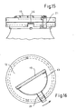
Figur 11 Figur 13- eine Teilansicht des geöffneten Verschlusses von Vorn,
Figur 14- eine Teilansicht des geschlossenen Verschlusses von Vorn,
Figur 15- eine der
Figur 14 entsprechende Ansicht, bei der das drehba- re Verschlussteil sich in einer Zwischenstelle zwischen der entriegelten und verriegelten Position befindet, Figur 16- eine Draufsicht auf das in
Figur 15 Figur 17- eine Schnittansicht des Verschlussteils in der verriegelten Stellung und
Figur 18- eine Draufsicht auf das Verschlussteil in der in
Figur 17
- FIG. 1
- a perspective view of the Dosierbehältnises according to the invention,
- FIG. 2
- a longitudinal section through the container
FIG. 1 . - FIG. 3
- a cross section along the lines III-III in
FIG. 2 . - FIG. 4
- a partial section through the Dosierbehältnis in a tilted state,
- FIG. 5
- a sectional view taken along the line VV in
FIG. 4 . - FIG. 6
- a longitudinal section through the container in opposite the Aufstelllage tilted position (back dosage),
- FIG. 7
- one of the
FIG. 6 corresponding sectional view of the metering ratio in the opposite tilted position with the metering channel closed, - FIGS. 8 and 9
- partial views of alternative configurations of the metering ratio in section,
- FIG. 10
- 8 is an exploded perspective view of the closure for the removal opening of the metering container according to the invention,
- FIG. 11
- a sectional partial view of the attached to the removal opening closure,
- FIG. 12
- along the lines XII-XII in
FIG. 11 . - FIG. 13
- a partial view of the opened closure from the front,
- FIG. 14
- a partial view of the closed closure of front,
- FIG. 15
- one of the
FIG. 14 corresponding view, in which the rotatable locking part is in an intermediate position between the unlocked and locked position, - FIG. 16
- a top view of the in
FIG. 15 illustrated figure part in the corresponding angular position, - FIG. 17
- a sectional view of the closure member in the locked position and
- FIG. 18
- a plan view of the closure part in the in
FIG. 17 marked position.
Das Dosierbehältnis gemäß der Erfindung ist in perspektivischer Ansicht in
Die Dosierflasche 1 ist insbesondere für die Aufnahme von körnigen bis pulverigen schüttfähigen Inhalten vorgesehen, diese kann allerdings für die Aufnahme von Flüssigkeiten optimiert sein.The
Die Dosierflasche 1 umfasst eine im Wesentlichen ebene Aufstellfläche 2, die bei den dargestellten Ausführungsbeispielen ausschließlich einen Vorratsbehälter 3 begrenzt, der einen wesentlichen Teil des Volumens der Dosierflasche 1 ausmacht. Neben dem Vorratsbehälter erstreckt sich über etwa 2/3 der Höhe der Dosierflasche 1 eine Dosierkammer 4, die ein gegenüber dem Vorratsbehälter 3 separates Volumen bildet. Die Dosierkammer 4 und der Vorratsbehälter 3 sind über einen Dosierkanal 5 miteinander verbunden.The
An dem von der Aufstellfläche 2 abliegenden Ende der Dosierflasche 1 ist diese mit einer Entnahmeöffnung 6 und einer Befüllöffnung 7 versehen.At the remote from the
Bei dem dargestellten Ausführungsbeispiel ist die Befüllöffnung 7 in dem Vorratsbehälter 3 vorgesehen, wohingegen die Entnahmeöffnung 6 die Dosierkammer 4 verschließt.In the illustrated embodiment, the filling opening 7 is provided in the
In konfektioniertem Zustand kann die Befüllöffnung 7 mit einer Verschlusskappe 8 dauerhaft verschlossen sein. Hierzu kann die Verschlusskappe 8 mit der Außenfläche der Dosierflasche randseitig der Entnahmeöffnung 6 verschweißt worden sein. Es ist alternativ allerdings auch möglich, die Befüllöffnung mit einem Schnapp- oder Schraubverschluss zu verschließen. Bei dem beschriebenen Behälter ist allerdings eine Wiederbefüllung nach Konfektionierung nicht vorgesehen.In the assembled state, the filling opening 7 can be permanently closed with a closure cap 8. For this purpose, the closure cap 8 may have been welded to the outer surface of the metering bottle at the edge of the
Die Entnahmeöffnung 6 ist hingegen mit einem wiederverschließbaren Deckelverschluss 9 verschlossen. Der Deckelverschluss 9 wird nachstehend im Einzelnen erläutert werden.The
Die Dosierkammer 4 und der Vorratsbehälter 3 sind durch einen Materialsteg 10 miteinander verbunden, wobei dieser Materialsteg 10 durch Wand-zu-Wand-Verschweißung beim Extrusionsblasformen der Dosierflasche 1 erhalten wurde. Die Dosierkammer 4 und der Vorratsbehälter 3 können nur über den mittels eines Absperrorgans verschließbaren Dosierkanal 5 miteinander kommunizieren.The
Eine Entnahme von Füllgut aus der Dosierflasche 1 erfolgt zunächst von dem Vorratsbehälter 3 in die Dosierkammer 4 und von der Dosierkammer 4 durch die Entnahmeöffnung 6.A removal of contents from the
Im Folgenden wird zunächst Bezug genommen auf die
Wie insbesondere den Schnittansichten in
Wie insbesondere der Zusammenschau der
Bei den in den
Der Absperrschieber 11 als Absperrorgan ist drehfest mit einem drehbaren Verschlussteil 12 des Deckelverschlusses 9 verbunden (siehe
An dem drehbaren Verschlussteil 12 ist wiederum eine Verschlussklappe 13 angelenkt, die nur in einer Winkelstellung des drehbaren Verschlussteils 12 geöffnet werden kann, und zwar in derjenigen Winkelstellung in der der Absperrschieber 11 den Dosierkanal 5 verschließt. Das drehbare Verschlussteil 12 und der Absperrschieber 11 sind über ein einstückig an dem drehbaren Verschlussteil 12 vorgesehenen Rastzapfen 14 drehfest miteinander verbunden. Der Rastzapfen 14 ist in der
Die Verschlussklappe ist bei dem dargestellten Ausführungsbeispiel über ein Scharnier 15 mit einem Scharnierstift 16 an dem drehbaren Verschlussteil 12 angeschlagen, alternativ kann das Scharnier 15 als Filmscharnier ausgebildet sein. Zwischen dem drehbaren Verschlussteil 12 und dem Absperrschieber 11 ist ein bezüglich der Entnahmeöffnung 6 drehfest angeordnetes Verschlussteil 17 vorgesehen. Zwischen dem drehfesten Verschlussteil 17 und dem Absperrschieber 11 ist eine Dichtscheibe 18 aus einem elastischen Kunststoff angeordnet.The closure flap is struck in the illustrated embodiment via a
Der Absperrschieber 11 ist einstückig mit einer kreisrunden Stauscheibe 19 verbunden, deren Durchmesser dem Durchmesser der Entnahmeöffnung etwa entspricht und welcher als Lochblende mit jeweils zwei viertelkreisförmig ausgebildeten Durchbrechungen 20 a versehen ist. Entsprechende Durchbrechungen 20 b, 20 c und 20 d sind jeweils in der Dichtscheibe 18 in dem drehfesten Verschlussteil 17 und in dem drehbarem Verschlussteil 12 vorgesehen. Weiterhin sind das drehfeste Verschlussteil 17, die Dichtscheibe 18 und die Stauscheibe 19 mit einer zentralen, kreisförmigen Befestigungsbohrung 25 versehen, die von dem Rastzapfen 14 durchsetzt wird, der eine drehfeste Verbindung zwischen den Verschlussteilen 17 und 12 herstellt. Dabei werden das drehfeste Verschlussteil 17 und die Stauscheibe 19 unter Zwischenlage der Dichtscheibe 18 gegeneinander gehalten, wobei die Stauscheibe 19 und der damit einstückig verbundene Absperrschieber 11 jede Drehbewegung des drehbaren Verschlussteils 12 mitvollziehen.The
Es ist ohne Weiteres ersichtlich, dass nur in der Winkelstellung des drehbaren Verschlussteils 12, die in den
In dieser Winkelstellung des drehbaren Verschlussteils 12 befindet sich der Absperrschieber 11 in der in
Andererseits ist, wie dies nachstehend noch erläutert wird, ein Auf- und Zuklappen der Verschlussklappe 13 nur in dieser Winkelstellung möglich.On the other hand, as will be explained below, opening and closing the
Die Verschlussklappe 13 ist mit einem im Querschnitt C-förmigen hinterschnittenen Sicherungsbügel 21 versehen, dessen Querschnittsprofil so ausgebildet ist, dass dieser das randseitige Querschnittsprofil des drehfesten Verschlussteils 17 formschlüssig umgreifen kann. Sowohl in dem drehbaren Verschlussteil 12 als auch in dem drehfesten Verschlussteil 17 ist jeweils eine randseitig gelegene rechteckige Ausnehmung 22 vorgesehen. Beide Ausnehmungen 22 sind etwa von gleicher Breite und liegen in der in
Sodann lässt sich das drehbare Verschlussteil 12 in die in
Sodann kann das drehbare Verschlussteil 12 in eine Winkelstellung gebracht werden, die ein Öffnen der Verschlussklappe 13 erlaubt. In dieser Winkelstellung ist der Dosierkanal 5 durch den Absperrschieber verschlossen, sodass eine Entnahme aus der Dosierkammer 4 möglich ist, ohne das Füllgut aus dem Vorratsbehälter 3 in die Dosierkammer 4 nachfließt, wie dies in
Der Absperrschieber 11 ist von seiner Formgebung und von seinem Funktionsprinzip wie ein Muschelschieber ausgebildet.The
Eine alternative Ausgestaltung der Dosierkammer 4 und des Dosierkanals 5 sind in
Eine weitere Ausgestaltung der Dosierkammer und der Anordnung des Dosierkanals ist in
Zu dem Deckelverschluss 9 ist noch erwähnenswert, dass, um eine entsprechende Dichtigkeit bei feinpulverigem oder flüssigem Füllgut zu erzielen, auf der Innenseite, d. h. auf der die Dichtscheibe 18 vorgesehenen Seite des drehfesten Verschlussteils, eine umlaufende Dichtrippe vorgesehen ist, die sich bei zusammengesetztem Verschluss in die Dichtscheibe 18 eindrückt.To the
Weiterhin sind an der Unterseite des Verschlussteils 17 in dem Bereich, der von dem Verschlussbügel 21 hintergriffen wird, wie dies in
Um ein Auflaufen des Entriegelungsstifts 21 auf die Federzunge 24 zu erleichtern, ist der Entriegelungsstift 23 jeweils seitlich angeschrägt.In order to facilitate emergence of the unlocking
- 1.1.
- Dosierflasche 2.AufstellflächeDosing bottle 2.Astellstellfläche
- 3.Third
-
Vorratsbehälter 4. Dosierkammer
Reservoir 4. Dosage chamber - 5.5th
- Dosierkanalmetering
- 6.6th
- Entnahmeöffnungremoval opening
- 7.7th
- Befüllöffnungfilling
- 8.8th.
- Verschlusskappecap
- 9.9th
- Deckelverschlusslid closure
- 10.10th
- Materialstegmaterial web
- 11.11th
- AbsperrschieberGate valves
- 12.12th
- drehbares Verschlussteilrotatable closure part
- 13.13th
- Verschlussklappeflap
- 14.14th
- Rastzapfenlatching pin
- 15.15th
- Scharnierhinge
- 16.16th
- Scharnierzapfenhinge pin
- 17.17th
- drehbares Verschlussteilrotatable closure part
- 18.18th
- Dichtscheibesealing washer
- 19.19th
- Stauscheibebaffle plate
- 20a, b, c, d20a, b, c, d
- Durchbrechungenperforations
- 21.21st
- Verschlussbügelwith clasps
- 22.22nd
- Ausnehmungenrecesses
- 23.23rd
- EntrieglungsstiftEntrieglungsstift
- 24.24th
- Federzungespring tongue
- 25.25th
- Befestigungsbohrungmounting hole
Claims (11)
- Dosing receptacle, in particular a dosing bottle (1) with at least one storage container (3) and at least one dosing chamber (4) which are connected to one another via a dosing aperture, wherein the dosing chamber (4) is provided with at least one removal aperture (6) which is at the top in the standing position and which is arranged opposite a face (2) of the dosing receptacle on which it stands, and wherein the dosing chamber (4) extends alongside the storage container (3) in the standing position, the dosing aperture is provided with a shut-off component (11) and said shut-off component can be actuated via a closure belonging to the removal aperture (6), characterised in that, when the removal aperture (6) is open, the shut-off component is located in the position that closes the dosing aperture.
- Dosing receptacle according to claim 1, characterised in that the shut-off component is constructed as a shut-off slide (11) which is connected to a rotatable closure belonging to the removal aperture (6).
- Dosing receptacle according to either of claims 1 or 2, characterised in that, when the removal aperture (6) is closed, the shut-off component is located in the position that unblocks the dosing aperture.
- Dosing receptacle according to one of claims 1 to 3, characterised in that the storage container (3) and the dosing chamber (4) are connected to one another via a dosing duct (5) which tapers in the direction of said dosing chamber (4).
- Dosing receptacle according to one of claims 1 to 4, characterised in that the dosing duct (5) extends at an angle to the level of the filling product when the receptacle is standing.
- Dosing receptacle according to one of claims 1 to 5, characterised in that the dosing aperture or the dosing duct (5) opens into the upper region of the dosing chamber (4) when the dosing receptacle is in the standing position.
- Dosing receptacle according to one of claims 1 to 6, characterised in that the removal aperture (6) is provided with a multipart closure, a first closure part being constructed as a rotatable closure part (12) and a second closure part being constructed as a pivotable closure flap (13).
- Dosing receptacle according to claim 7, characterised in that the second closure part is provided with a locking element which can only be locked and unlocked in one angular position of the first closure part.
- Dosing receptacle according to one of claims 1 to 8, characterised in that the closure of the removal aperture (6) comprises a perforated screen which is unblocked in one angular position of the rotatable closure part (12).
- Dosing receptacle according to one of claims 1 to 9, characterised in that the dosing chamber (4) and the storage container (3) are connected to one another in one piece.
- Dosing receptacle according to one of claims 1 to 10, characterised in that said dosing receptacle has been obtained in one piece by extrusion blow moulding.
Priority Applications (1)
| Application Number | Priority Date | Filing Date | Title |
|---|---|---|---|
| PL10003187T PL2243721T3 (en) | 2009-04-23 | 2010-03-25 | Dosing container |
Applications Claiming Priority (1)
| Application Number | Priority Date | Filing Date | Title |
|---|---|---|---|
| DE102009018349A DE102009018349B4 (en) | 2009-04-23 | 2009-04-23 | Dosierbehältnis |
Publications (2)
| Publication Number | Publication Date |
|---|---|
| EP2243721A1 EP2243721A1 (en) | 2010-10-27 |
| EP2243721B1 true EP2243721B1 (en) | 2013-01-23 |
Family
ID=42314796
Family Applications (1)
| Application Number | Title | Priority Date | Filing Date |
|---|---|---|---|
| EP10003187A Not-in-force EP2243721B1 (en) | 2009-04-23 | 2010-03-25 | Dosing container |
Country Status (3)
| Country | Link |
|---|---|
| EP (1) | EP2243721B1 (en) |
| DE (1) | DE102009018349B4 (en) |
| PL (1) | PL2243721T3 (en) |
Cited By (1)
| Publication number | Priority date | Publication date | Assignee | Title |
|---|---|---|---|---|
| US11052415B2 (en) | 2016-03-10 | 2021-07-06 | Ecolab Usa Inc. | Measured dosing and spray bottle for multi-use applications and associated method of using |
Families Citing this family (8)
| Publication number | Priority date | Publication date | Assignee | Title |
|---|---|---|---|---|
| CN102424173B (en) * | 2011-08-20 | 2013-08-21 | 钟婕 | Liquid quantity control current limitation supply device |
| NL2007421C2 (en) | 2011-09-15 | 2013-03-18 | Debski Reddingius | HOLDER FOR A LIQUID. |
| AU2013251835B2 (en) | 2012-04-26 | 2017-02-23 | Bayer Cropscience Ag | Dosing device |
| DK2841886T3 (en) | 2012-04-26 | 2016-04-25 | Bayer Cropscience Ag | DOSING DEVICE AND METHOD OF DOSING AND DISPENSING USING THE DOSING DEVICE |
| MD4550C1 (en) * | 2017-02-15 | 2018-09-30 | Михаил БАЛАН | Container for metered delivery of liquid |
| JP2020019541A (en) * | 2018-08-01 | 2020-02-06 | 凸版印刷株式会社 | Cap with measuring function |
| CN109573352B (en) * | 2019-01-16 | 2023-09-29 | 夏敏 | Cathartic bottle device for component guiding taking |
| DE102021003773A1 (en) | 2021-07-23 | 2023-01-26 | Mona Frey | dispenser |
Family Cites Families (11)
| Publication number | Priority date | Publication date | Assignee | Title |
|---|---|---|---|---|
| US3258177A (en) * | 1965-08-31 | 1966-06-28 | Alfred L Ellis | Measuring and dispensing device for granular material |
| DE1911628A1 (en) * | 1969-03-07 | 1970-09-24 | Stuebbe Friedrich | Metering container for liquids and free- - running solids |
| US4144989A (en) * | 1977-09-12 | 1979-03-20 | Joy Walter S | Granular material dispenser |
| DE9017370U1 (en) * | 1990-12-22 | 1992-04-16 | Effem Gmbh, 2810 Verden, De | |
| IT1258631B (en) | 1992-11-02 | 1996-02-27 | Taplast Srl | PERFECTED DOSER-DISPENSER DEVICE FOR GRANULAR OR POWDER PRODUCTS |
| US5518152A (en) * | 1995-06-06 | 1996-05-21 | E. S. Robbins Corporation | Measuring canister |
| US5971216A (en) * | 1997-11-26 | 1999-10-26 | Robbins, Iii; Edward S. | Measuring canister with sliding closure |
| JP2000281154A (en) * | 1999-03-30 | 2000-10-10 | Createchnic Ag | Dispensing bottle |
| US6378735B1 (en) * | 2001-04-04 | 2002-04-30 | Lien-Fang Chu | Device for obtaining contents in a container at desired quantity |
| DE202007008903U1 (en) | 2007-06-26 | 2007-08-23 | Werner & Mertz Gmbh | Dosing bottle for bulk material such as granules or granular material comprises a dosing chamber arranged below a supply container and connected to the supply container via a dosing opening or channel |
| WO2009012429A1 (en) * | 2007-07-18 | 2009-01-22 | Sonoco Development, Inc. | Portion dispenser |
-
2009
- 2009-04-23 DE DE102009018349A patent/DE102009018349B4/en not_active Expired - Fee Related
-
2010
- 2010-03-25 PL PL10003187T patent/PL2243721T3/en unknown
- 2010-03-25 EP EP10003187A patent/EP2243721B1/en not_active Not-in-force
Cited By (2)
| Publication number | Priority date | Publication date | Assignee | Title |
|---|---|---|---|---|
| US11052415B2 (en) | 2016-03-10 | 2021-07-06 | Ecolab Usa Inc. | Measured dosing and spray bottle for multi-use applications and associated method of using |
| US11504729B2 (en) | 2016-03-10 | 2022-11-22 | Ecolab Usa Inc. | Measured dosing and spray bottle for multi-use applications and associated method of using |
Also Published As
| Publication number | Publication date |
|---|---|
| DE102009018349A1 (en) | 2010-11-18 |
| EP2243721A1 (en) | 2010-10-27 |
| DE102009018349B4 (en) | 2013-12-05 |
| PL2243721T3 (en) | 2013-06-28 |
Similar Documents
| Publication | Publication Date | Title |
|---|---|---|
| EP2243721B1 (en) | Dosing container | |
| DE3527124A1 (en) | CONTAINER WITH AT LEAST TWO CHAMBERS TO RECEIVE LIQUID AND POWDER-MADE SUBSTANCES, IN PARTICULAR COFFEE POWDER, MILK AND / OR SUGAR | |
| DE212008000119U1 (en) | Dosing device for dosing a liquid product | |
| WO1992011188A1 (en) | Dispenser for powdered materials in particular with a reservoir chamber, metering chamber and dispensing chamber | |
| EP0165276B1 (en) | Doser dispenser | |
| EP0077556A2 (en) | Container for concentrates | |
| EP0695697B1 (en) | Collecting and dispersing device for bulk goods | |
| EP0133264B1 (en) | Dosing apparatus | |
| DE2262384C3 (en) | Dispenser for the measured dispensing of powdery material or the like | |
| WO1999044019A1 (en) | Dosing device for a container | |
| EP2394927B1 (en) | Two-part plastic dosing cap | |
| EP2008940B1 (en) | Dosage bottle | |
| EP1108656B1 (en) | Multicomponent container for storing and distributing liquid or pasty products | |
| DE3416008A1 (en) | DOSING UNIT | |
| DE3435653A1 (en) | Closure lid | |
| DE19549440C2 (en) | dispenser | |
| DE2233126C2 (en) | Spreader | |
| DE3409632C2 (en) | ||
| DE19500830C1 (en) | Multichamber container with rotatable multichamber dispensing head | |
| DE19507402C2 (en) | Packaging for bulk goods | |
| DE3236552A1 (en) | Pump metering closure | |
| DE3605245A1 (en) | Metering and filling apparatus for free-flowing material | |
| DE3809548A1 (en) | Metering device for pulverulent, flocculent or fine-grained food products | |
| EP1056990B1 (en) | Dosing device for a container | |
| DE102006034083B3 (en) | Valve device for valve system, has movement limiting unit e.g. locking device, operated such that one unit is movable only within another unit and passage opening is arranged within latter unit |
Legal Events
| Date | Code | Title | Description |
|---|---|---|---|
| PUAI | Public reference made under article 153(3) epc to a published international application that has entered the european phase |
Free format text: ORIGINAL CODE: 0009012 |
|
| AK | Designated contracting states |
Kind code of ref document: A1 Designated state(s): AT BE BG CH CY CZ DE DK EE ES FI FR GB GR HR HU IE IS IT LI LT LU LV MC MK MT NL NO PL PT RO SE SI SK SM TR |
|
| AX | Request for extension of the european patent |
Extension state: AL BA ME RS |
|
| 17P | Request for examination filed |
Effective date: 20110412 |
|
| GRAP | Despatch of communication of intention to grant a patent |
Free format text: ORIGINAL CODE: EPIDOSNIGR1 |
|
| GRAS | Grant fee paid |
Free format text: ORIGINAL CODE: EPIDOSNIGR3 |
|
| GRAA | (expected) grant |
Free format text: ORIGINAL CODE: 0009210 |
|
| AK | Designated contracting states |
Kind code of ref document: B1 Designated state(s): AT BE BG CH CY CZ DE DK EE ES FI FR GB GR HR HU IE IS IT LI LT LU LV MC MK MT NL NO PL PT RO SE SI SK SM TR |
|
| REG | Reference to a national code |
Ref country code: GB Ref legal event code: FG4D Free format text: NOT ENGLISH |
|
| REG | Reference to a national code |
Ref country code: CH Ref legal event code: EP |
|
| REG | Reference to a national code |
Ref country code: AT Ref legal event code: REF Ref document number: 594825 Country of ref document: AT Kind code of ref document: T Effective date: 20130215 Ref country code: CH Ref legal event code: EP |
|
| REG | Reference to a national code |
Ref country code: IE Ref legal event code: FG4D Free format text: LANGUAGE OF EP DOCUMENT: GERMAN |
|
| REG | Reference to a national code |
Ref country code: CH Ref legal event code: NV Representative=s name: FIAMMENGHI-FIAMMENGHI, CH |
|
| REG | Reference to a national code |
Ref country code: DE Ref legal event code: R096 Ref document number: 502010002167 Country of ref document: DE Effective date: 20130321 |
|
| REG | Reference to a national code |
Ref country code: NL Ref legal event code: T3 |
|
| REG | Reference to a national code |
Ref country code: LT Ref legal event code: MG4D |
|
| REG | Reference to a national code |
Ref country code: PL Ref legal event code: T3 |
|
| PG25 | Lapsed in a contracting state [announced via postgrant information from national office to epo] |
Ref country code: BG Free format text: LAPSE BECAUSE OF FAILURE TO SUBMIT A TRANSLATION OF THE DESCRIPTION OR TO PAY THE FEE WITHIN THE PRESCRIBED TIME-LIMIT Effective date: 20130423 Ref country code: SE Free format text: LAPSE BECAUSE OF FAILURE TO SUBMIT A TRANSLATION OF THE DESCRIPTION OR TO PAY THE FEE WITHIN THE PRESCRIBED TIME-LIMIT Effective date: 20130123 Ref country code: NO Free format text: LAPSE BECAUSE OF FAILURE TO SUBMIT A TRANSLATION OF THE DESCRIPTION OR TO PAY THE FEE WITHIN THE PRESCRIBED TIME-LIMIT Effective date: 20130423 Ref country code: LT Free format text: LAPSE BECAUSE OF FAILURE TO SUBMIT A TRANSLATION OF THE DESCRIPTION OR TO PAY THE FEE WITHIN THE PRESCRIBED TIME-LIMIT Effective date: 20130123 Ref country code: ES Free format text: LAPSE BECAUSE OF FAILURE TO SUBMIT A TRANSLATION OF THE DESCRIPTION OR TO PAY THE FEE WITHIN THE PRESCRIBED TIME-LIMIT Effective date: 20130504 Ref country code: IS Free format text: LAPSE BECAUSE OF FAILURE TO SUBMIT A TRANSLATION OF THE DESCRIPTION OR TO PAY THE FEE WITHIN THE PRESCRIBED TIME-LIMIT Effective date: 20130523 |
|
| PG25 | Lapsed in a contracting state [announced via postgrant information from national office to epo] |
Ref country code: FI Free format text: LAPSE BECAUSE OF FAILURE TO SUBMIT A TRANSLATION OF THE DESCRIPTION OR TO PAY THE FEE WITHIN THE PRESCRIBED TIME-LIMIT Effective date: 20130123 Ref country code: LV Free format text: LAPSE BECAUSE OF FAILURE TO SUBMIT A TRANSLATION OF THE DESCRIPTION OR TO PAY THE FEE WITHIN THE PRESCRIBED TIME-LIMIT Effective date: 20130123 Ref country code: GR Free format text: LAPSE BECAUSE OF FAILURE TO SUBMIT A TRANSLATION OF THE DESCRIPTION OR TO PAY THE FEE WITHIN THE PRESCRIBED TIME-LIMIT Effective date: 20130424 Ref country code: PT Free format text: LAPSE BECAUSE OF FAILURE TO SUBMIT A TRANSLATION OF THE DESCRIPTION OR TO PAY THE FEE WITHIN THE PRESCRIBED TIME-LIMIT Effective date: 20130523 Ref country code: SI Free format text: LAPSE BECAUSE OF FAILURE TO SUBMIT A TRANSLATION OF THE DESCRIPTION OR TO PAY THE FEE WITHIN THE PRESCRIBED TIME-LIMIT Effective date: 20130123 |
|
| PG25 | Lapsed in a contracting state [announced via postgrant information from national office to epo] |
Ref country code: HR Free format text: LAPSE BECAUSE OF FAILURE TO SUBMIT A TRANSLATION OF THE DESCRIPTION OR TO PAY THE FEE WITHIN THE PRESCRIBED TIME-LIMIT Effective date: 20130123 |
|
| PG25 | Lapsed in a contracting state [announced via postgrant information from national office to epo] |
Ref country code: MC Free format text: LAPSE BECAUSE OF NON-PAYMENT OF DUE FEES Effective date: 20130331 Ref country code: CZ Free format text: LAPSE BECAUSE OF FAILURE TO SUBMIT A TRANSLATION OF THE DESCRIPTION OR TO PAY THE FEE WITHIN THE PRESCRIBED TIME-LIMIT Effective date: 20130123 Ref country code: SK Free format text: LAPSE BECAUSE OF FAILURE TO SUBMIT A TRANSLATION OF THE DESCRIPTION OR TO PAY THE FEE WITHIN THE PRESCRIBED TIME-LIMIT Effective date: 20130123 Ref country code: EE Free format text: LAPSE BECAUSE OF FAILURE TO SUBMIT A TRANSLATION OF THE DESCRIPTION OR TO PAY THE FEE WITHIN THE PRESCRIBED TIME-LIMIT Effective date: 20130123 Ref country code: RO Free format text: LAPSE BECAUSE OF FAILURE TO SUBMIT A TRANSLATION OF THE DESCRIPTION OR TO PAY THE FEE WITHIN THE PRESCRIBED TIME-LIMIT Effective date: 20130123 Ref country code: DK Free format text: LAPSE BECAUSE OF FAILURE TO SUBMIT A TRANSLATION OF THE DESCRIPTION OR TO PAY THE FEE WITHIN THE PRESCRIBED TIME-LIMIT Effective date: 20130123 |
|
| PG25 | Lapsed in a contracting state [announced via postgrant information from national office to epo] |
Ref country code: CY Free format text: LAPSE BECAUSE OF FAILURE TO SUBMIT A TRANSLATION OF THE DESCRIPTION OR TO PAY THE FEE WITHIN THE PRESCRIBED TIME-LIMIT Effective date: 20130123 |
|
| PLBE | No opposition filed within time limit |
Free format text: ORIGINAL CODE: 0009261 |
|
| STAA | Information on the status of an ep patent application or granted ep patent |
Free format text: STATUS: NO OPPOSITION FILED WITHIN TIME LIMIT |
|
| PG25 | Lapsed in a contracting state [announced via postgrant information from national office to epo] |
Ref country code: IT Free format text: LAPSE BECAUSE OF FAILURE TO SUBMIT A TRANSLATION OF THE DESCRIPTION OR TO PAY THE FEE WITHIN THE PRESCRIBED TIME-LIMIT Effective date: 20130123 |
|
| 26N | No opposition filed |
Effective date: 20131024 |
|
| REG | Reference to a national code |
Ref country code: IE Ref legal event code: MM4A |
|
| PG25 | Lapsed in a contracting state [announced via postgrant information from national office to epo] |
Ref country code: IE Free format text: LAPSE BECAUSE OF NON-PAYMENT OF DUE FEES Effective date: 20130325 |
|
| REG | Reference to a national code |
Ref country code: DE Ref legal event code: R097 Ref document number: 502010002167 Country of ref document: DE Effective date: 20131024 |
|
| REG | Reference to a national code |
Ref country code: DE Ref legal event code: R082 Ref document number: 502010002167 Country of ref document: DE Representative=s name: KIERDORF RITSCHEL RICHLY PATENTANWAELTE PARTG , DE Ref country code: DE Ref legal event code: R082 Ref document number: 502010002167 Country of ref document: DE Representative=s name: KIERDORF RITSCHEL PATENTANWAELTE PARTG MBB, DE Ref country code: DE Ref legal event code: R082 Ref document number: 502010002167 Country of ref document: DE Representative=s name: RICHLY & RITSCHEL PATENTANWAELTE PARTG MBB, DE |
|
| PG25 | Lapsed in a contracting state [announced via postgrant information from national office to epo] |
Ref country code: MT Free format text: LAPSE BECAUSE OF FAILURE TO SUBMIT A TRANSLATION OF THE DESCRIPTION OR TO PAY THE FEE WITHIN THE PRESCRIBED TIME-LIMIT Effective date: 20130123 |
|
| REG | Reference to a national code |
Ref country code: FR Ref legal event code: PLFP Year of fee payment: 6 |
|
| PG25 | Lapsed in a contracting state [announced via postgrant information from national office to epo] |
Ref country code: SM Free format text: LAPSE BECAUSE OF FAILURE TO SUBMIT A TRANSLATION OF THE DESCRIPTION OR TO PAY THE FEE WITHIN THE PRESCRIBED TIME-LIMIT Effective date: 20130123 |
|
| PG25 | Lapsed in a contracting state [announced via postgrant information from national office to epo] |
Ref country code: TR Free format text: LAPSE BECAUSE OF FAILURE TO SUBMIT A TRANSLATION OF THE DESCRIPTION OR TO PAY THE FEE WITHIN THE PRESCRIBED TIME-LIMIT Effective date: 20130123 |
|
| PG25 | Lapsed in a contracting state [announced via postgrant information from national office to epo] |
Ref country code: MK Free format text: LAPSE BECAUSE OF FAILURE TO SUBMIT A TRANSLATION OF THE DESCRIPTION OR TO PAY THE FEE WITHIN THE PRESCRIBED TIME-LIMIT Effective date: 20130123 Ref country code: HU Free format text: LAPSE BECAUSE OF FAILURE TO SUBMIT A TRANSLATION OF THE DESCRIPTION OR TO PAY THE FEE WITHIN THE PRESCRIBED TIME-LIMIT; INVALID AB INITIO Effective date: 20100325 |
|
| REG | Reference to a national code |
Ref country code: FR Ref legal event code: PLFP Year of fee payment: 7 |
|
| REG | Reference to a national code |
Ref country code: FR Ref legal event code: PLFP Year of fee payment: 8 |
|
| REG | Reference to a national code |
Ref country code: FR Ref legal event code: PLFP Year of fee payment: 9 |
|
| PGFP | Annual fee paid to national office [announced via postgrant information from national office to epo] |
Ref country code: CH Payment date: 20210319 Year of fee payment: 12 Ref country code: NL Payment date: 20210319 Year of fee payment: 12 Ref country code: LU Payment date: 20210319 Year of fee payment: 12 Ref country code: FR Payment date: 20210323 Year of fee payment: 12 |
|
| PGFP | Annual fee paid to national office [announced via postgrant information from national office to epo] |
Ref country code: AT Payment date: 20210322 Year of fee payment: 12 Ref country code: BE Payment date: 20210319 Year of fee payment: 12 Ref country code: GB Payment date: 20210324 Year of fee payment: 12 Ref country code: PL Payment date: 20210311 Year of fee payment: 12 Ref country code: DE Payment date: 20210224 Year of fee payment: 12 |
|
| REG | Reference to a national code |
Ref country code: DE Ref legal event code: R119 Ref document number: 502010002167 Country of ref document: DE |
|
| REG | Reference to a national code |
Ref country code: CH Ref legal event code: PL |
|
| REG | Reference to a national code |
Ref country code: NL Ref legal event code: MM Effective date: 20220401 |
|
| REG | Reference to a national code |
Ref country code: AT Ref legal event code: MM01 Ref document number: 594825 Country of ref document: AT Kind code of ref document: T Effective date: 20220325 |
|
| GBPC | Gb: european patent ceased through non-payment of renewal fee |
Effective date: 20220325 |
|
| REG | Reference to a national code |
Ref country code: BE Ref legal event code: MM Effective date: 20220331 |
|
| PG25 | Lapsed in a contracting state [announced via postgrant information from national office to epo] |
Ref country code: NL Free format text: LAPSE BECAUSE OF NON-PAYMENT OF DUE FEES Effective date: 20220401 Ref country code: LU Free format text: LAPSE BECAUSE OF NON-PAYMENT OF DUE FEES Effective date: 20220325 Ref country code: LI Free format text: LAPSE BECAUSE OF NON-PAYMENT OF DUE FEES Effective date: 20220331 Ref country code: GB Free format text: LAPSE BECAUSE OF NON-PAYMENT OF DUE FEES Effective date: 20220325 Ref country code: FR Free format text: LAPSE BECAUSE OF NON-PAYMENT OF DUE FEES Effective date: 20220331 Ref country code: DE Free format text: LAPSE BECAUSE OF NON-PAYMENT OF DUE FEES Effective date: 20221001 Ref country code: CH Free format text: LAPSE BECAUSE OF NON-PAYMENT OF DUE FEES Effective date: 20220331 Ref country code: AT Free format text: LAPSE BECAUSE OF NON-PAYMENT OF DUE FEES Effective date: 20220325 |
|
| PG25 | Lapsed in a contracting state [announced via postgrant information from national office to epo] |
Ref country code: BE Free format text: LAPSE BECAUSE OF NON-PAYMENT OF DUE FEES Effective date: 20220331 |
|
| PG25 | Lapsed in a contracting state [announced via postgrant information from national office to epo] |
Ref country code: PL Free format text: LAPSE BECAUSE OF NON-PAYMENT OF DUE FEES Effective date: 20220325 |