EP2243242B1 - Method and arrangement in a wireless communication network - Google Patents
Method and arrangement in a wireless communication network Download PDFInfo
- Publication number
- EP2243242B1 EP2243242B1 EP09710382.4A EP09710382A EP2243242B1 EP 2243242 B1 EP2243242 B1 EP 2243242B1 EP 09710382 A EP09710382 A EP 09710382A EP 2243242 B1 EP2243242 B1 EP 2243242B1
- Authority
- EP
- European Patent Office
- Prior art keywords
- data block
- usf
- terminal
- parts
- modulation technique
- Prior art date
- Legal status (The legal status is an assumption and is not a legal conclusion. Google has not performed a legal analysis and makes no representation as to the accuracy of the status listed.)
- Active
Links
- 238000000034 method Methods 0.000 title claims description 197
- 238000004891 communication Methods 0.000 title claims description 52
- 238000004590 computer program Methods 0.000 claims description 76
- 238000012545 processing Methods 0.000 claims description 34
- 230000005540 biological transmission Effects 0.000 claims description 14
- 238000012790 confirmation Methods 0.000 claims description 6
- 230000010363 phase shift Effects 0.000 claims description 5
- 238000010586 diagram Methods 0.000 description 10
- 230000006870 function Effects 0.000 description 10
- 238000005204 segregation Methods 0.000 description 4
- 230000003139 buffering effect Effects 0.000 description 3
- 238000005516 engineering process Methods 0.000 description 3
- 238000013507 mapping Methods 0.000 description 3
- 230000003287 optical effect Effects 0.000 description 3
- 238000001228 spectrum Methods 0.000 description 2
- 241000760358 Enodes Species 0.000 description 1
- 230000001413 cellular effect Effects 0.000 description 1
- 238000012986 modification Methods 0.000 description 1
- 230000004048 modification Effects 0.000 description 1
- 238000010187 selection method Methods 0.000 description 1
Images


Classifications
-
- H—ELECTRICITY
- H04—ELECTRIC COMMUNICATION TECHNIQUE
- H04W—WIRELESS COMMUNICATION NETWORKS
- H04W72/00—Local resource management
- H04W72/04—Wireless resource allocation
-
- H—ELECTRICITY
- H04—ELECTRIC COMMUNICATION TECHNIQUE
- H04L—TRANSMISSION OF DIGITAL INFORMATION, e.g. TELEGRAPHIC COMMUNICATION
- H04L1/00—Arrangements for detecting or preventing errors in the information received
- H04L1/004—Arrangements for detecting or preventing errors in the information received by using forward error control
- H04L1/0072—Error control for data other than payload data, e.g. control data
-
- H—ELECTRICITY
- H04—ELECTRIC COMMUNICATION TECHNIQUE
- H04L—TRANSMISSION OF DIGITAL INFORMATION, e.g. TELEGRAPHIC COMMUNICATION
- H04L1/00—Arrangements for detecting or preventing errors in the information received
- H04L1/0078—Avoidance of errors by organising the transmitted data in a format specifically designed to deal with errors, e.g. location
- H04L1/0079—Formats for control data
- H04L1/008—Formats for control data where the control data relates to payload of a different packet
Definitions
- the present invention relates to a method and arrangement in a wireless communication network and, more in particular, to a mechanism for avoiding modulation segregation.
- EDGE Enhanced Data rates for. GSM Evolution
- 3GPP Third Generation Partnership Project
- GSM Global System for Mobile Telecommunications
- GERAN EDGE Radio Access Network
- GERAN/EDGE Evolution could be seen as a new packet of features as part of release 7 of the GERAN specifications.
- EGPRS2 which introduces higher order modulations and higher symbols rates for both uplink and downlink.
- Another part of that package is called Reduced Latency and reduces the Time Transmit Interval (TTI) from 20 ms to 10 ms.
- TTI Time Transmit Interval
- the feature, often called Reduced TTI (RTTI) currently puts requirements on the downlink transmission in order to still support legacy pre-release 7 terminals.
- RTTI Reduced TTI
- GMSK Gaussian Minimum Shift Keying
- 8PSK 8-Phase-shift keying
- QPSK Quadrature Phase-Shift Keying
- 16QAM 16-Quadrature Amplitude Modulation
- 32QAM 32-Quadrature Amplitude Modulation
- Uplink State Flag used to grant a particular terminal access to one, or more, uplink radio block(s).
- USB Uplink State Flag
- the USF could be sent in both RTTI mode, or the legacy way, in Basic Transmission Time Interval (BTTI) mode i.e. mapped over four consecutive Time Division Multiple Access (TDMA) frames, thus e.g. 20 ms.
- BTTI Basic Transmission Time Interval
- TDMA Time Division Multiple Access
- TDMA Time Division Multiple Access
- a prior art example regarding enhanced wireless transmission due to a modulation selection method is found in the European Patent Application EP 1871028 A1, published December 26, 2007 .
- the document presents a transmitter comprising a unit which evaluates the channel conditions for each frequency block and a modulation scheme determination unit determining at least a modulation scheme depending on the evaluated channel condition.
- the transmitter uses a single modulation technique for two consecutive radio blocks, as mentioned above.
- the problem with the existing solution is that the ability to support legacy terminals puts requirements on the downlink scheduler.
- the downlink scheduler needs to use the same modulation in two consecutive blocks. It frequently results in non-optimal choice of modulation for any or both of the two downlink blocks. This problem is sometimes called modulation segregation.
- the object is achieved by a method in a base station for transmitting information data to a terminal.
- the base station and the terminal are comprised within a wireless communication network.
- the information data comprises a first data block and a second data block.
- the first and second data blocks are arranged to be transmitted to the same terminal or to different terminals.
- the method comprises obtaining a first USF value and a second USF value, to be sent across the first data block and the second data block.
- the method also comprises obtaining a first modulation technique associated with the first data block. Further, the method comprises encoding first parts of the obtained first and second USF values and the first data block for the obtained first modulation technique.
- the method comprises modulating the encoded first parts of the first and second USF values and the encoded first data block, according to the obtained first modulation technique. Also, the method further comprises transmitting the modulated first parts of the first and second USF values and the modulated first data block. Further, the method in addition comprises obtaining a second modulation technique associated with the second data block. The method further additionally comprises encoding second parts of the obtained first and second USF values and the second data block for the obtained second modulation technique. Furthermore, the method also, in addition, comprises modulating the encoded second parts of the first and second USF values and the encoded second data block according to the obtained second modulation technique. Still further, the method comprises transmitting the modulated second parts of the first and second USF values and the modulated second data block.
- the object is also achieved by an arrangement in a base station for transmitting information data to a terminal.
- the base station and the terminal are comprised within a wireless communication network.
- the information data comprises a first data block and a second data block.
- the first and second data blocks are arranged to be transmitted to the same terminal, or to different terminals.
- the arrangement comprises a first obtaining unit.
- the first obtaining unit is adapted to obtain a first and a second USF value, to be sent across the first data block and the second data block.
- the arrangement comprises a second obtaining unit.
- the second obtaining unit is adapted to obtain a modulation technique associated with the first data block and/or the second data block.
- the arrangement comprises an encoding unit.
- the encoding unit is adapted to encode parts of the obtained first and second USF values and the first data block and/or the second data block for the obtained modulation technique. Furthermore, the arrangement also comprises a modulator unit. The modulator unit is adapted to modulate parts of the encoded first and second USF values and the first data block and/or the second data block according to the obtained modulation technique. Additionally, the method further comprises a transmitting unit. The transmitting unit is adapted to transmit the modulated parts of the first and second USF values and the modulated data block to the terminal.
- the object is also achieved by a computer program product, comprising instructions for performing method steps in a base station for transmitting information data to a terminal.
- the base station and the terminal are comprised within a wireless communication network.
- the information data comprises a first data block and a second data block.
- the first and second data blocks are arranged to be transmitted to the same terminal or to different terminals.
- the computer program product comprises instructions for obtaining a first and a second USF value, to be sent across the first data block and the second data block.
- the computer program product further comprises instructions for obtaining a first modulation technique associated with the first data block.
- the computer program product also, additionally comprises encoding first parts of the obtained first and second USF values and the first data block for the obtained first modulation technique.
- the computer program product also comprises modulating the encoded first parts of the first and second USF values and the encoded first data block, according to the obtained first modulation technique.
- the computer program product also comprises transmitting the modulated first parts of the first and second USF values and the modulated first data block.
- the computer program product further comprises obtaining a second modulation technique associated with the second data block.
- the computer program product also comprises encoding second parts of the obtained first and second USF values and the second data block for the obtained second modulation technique.
- the computer program product additionally comprises modulating the encoded second parts of the first and second USF values and the encoded second data block according to the obtained second modulation technique.
- the computer program product comprises transmitting the modulated second parts of the first and second USF values and the modulated second data block when the computer program product is run on a processing unit comprised within the base station.
- the object is achieved by a method in a terminal, for receiving information data from a base station.
- the base station and the terminal are comprised within a wireless communication network.
- the information data comprises a first data block and a second data block.
- the method comprises receiving modulated first parts of a first and second USF values, and the modulated first data block, from the base station.
- the method comprises demodulating the received first parts of the first and second USF values and the received first data block, according to a first modulation technique.
- the method in addition comprises receiving modulated second parts of the first and second USF values and the modulated second data block, from the base station.
- the method also comprises demodulating the received second parts of the first and second USF values and the received second data block, according to a second modulation technique. Additionally, the method furthermore comprises extracting the information data by adding the demodulated second data block to the demodulated first data block. Still further yet, the method in addition comprise decoding the extracted information data.
- the object is also achieved by an arrangement in a terminal, for receiving information data from a base station.
- the base station and the terminal are comprised within a wireless communication network.
- the information data comprises a first data block and a second data block.
- the arrangement comprises a receiving unit.
- the receiving unit is adapted to receive a modulated part of a first USF value and a second USF value, and a modulated data block from the base station.
- the arrangement comprises a demodulation unit.
- the demodulation unit is adapted to demodulate the received parts of the first and second USF values and the received data block.
- the arrangement comprises an extracting unit.
- the extracting unit is adapted to extract the information data by adding a demodulated data block to another demodulated data block.
- the arrangement comprises a decoding unit.
- the decoding unit is adapted to decode the extracted information data.
- the object is also achieved by a computer program product, comprising instructions for performing method steps in a terminal, for receiving information data from a base station.
- the base station and the terminal are comprised within a wireless communication network.
- the information data comprises a first data block and a second data block.
- the computer program product comprises instructions for receiving modulated first parts of a first USF value and a second USF value, and the modulated first data block, from the base station.
- the computer program product comprises instructions for demodulating the received first parts of the first and second USF values and the received first data block, according to a first modulation technique.
- the computer program product comprises instructions for receiving modulated second parts of the first and second USF values and the modulated second data block, from the base station.
- the computer program product comprises instructions for demodulating the received second parts of the first and second USF values and the received second data block, according to a second modulation technique. Additionally, the computer program product comprises instructions for extracting the information data by adding the demodulated second data block to the demodulated first data block. Further yet, the computer program product also comprises instructions for decoding the extracted information data when the computer program product is run on a processing unit comprised within the terminal.
- the object is achieved by a method in a control node for supporting a base station in transmitting information data to a terminal.
- the control node, the base station and the terminal are comprised within a wireless communication network.
- the information data comprises a first data block and a second data block.
- the method comprises providing modulation information associated with the first data block and/or the second data block to be sent from the base station to the terminal.
- the method further comprises providing a first USF value and a second USF value associated with the first data block and/or the second data block to be sent from the base station to the terminal.
- the object is also achieved by an arrangement in a control node for supporting a base station in transmitting information data to a terminal.
- the control node, the base station and the terminal are comprised within a wireless communication network.
- the information data comprises a first data block and a second data block.
- the arrangement comprises a first providing unit.
- the first providing unit is adapted to provide modulation information associated with the first data block and/or the second data block to be sent from the base station to the terminal.
- the arrangement further comprises a second providing unit, adapted to provide a first USF value and a second USF value, associated with the first data block and/or the second data block to be sent from the base station to the terminal.
- the object is also achieved by a computer program product, comprising instructions for performing method steps in a control node for supporting a base station in transmitting information data to a terminal.
- the control node, the base station and the terminal are comprised within a wireless communication network.
- the information data comprises a first data block and a second data block.
- the computer program product comprises instructions for providing modulation information associated with the first data block and/or the second data block to be sent from the base station to the terminal.
- the computer program product comprises instructions for providing a first USF value and a second USF value associated with the first data block and/or the second data block to be sent from the base station to the terminal when the computer program product is run on a processing unit comprised within the control node.
- each transmitted data block using the at the moment most accurate modulation technique, when start transmitting each data block.
- This is accomplished by modifying the uplink scheduling parameters in such a way that the downlink scheduler can work freely without risk of introducing modulation segregation.
- different modulations are used in two consecutive RTTI radio blocks. Thereby increased spectrum and hardware utilization is generated. This improves spectrum efficiency but still gives support for legacy terminals when introducing the feature Reduced Latency. Thus an improved performance within a wireless communication network is provided.
- the present solution is defined as a method, a computer program product and an arrangement in a base station, a method, a computer program product and an arrangement in a terminal, and a method, a computer program product and an arrangement in a control node, which may be put into practice in the embodiments described below.
- the present solution may, however, be embodied in many different forms and should not be construed as limited to the embodiments set forth herein; rather, these embodiments are provided so that this disclosure will be thorough and complete, and will fully convey the scope of the present solution.
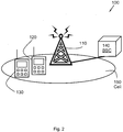
- FIG. 2 is a schematic illustration over a wireless communication network 100.
- the wireless communication network 100 comprises at least one base station 110 and is arranged to comprise a plurality of terminals 120, 130.
- the base station 110 may send and receive wireless signals to and from the terminals 120, 130 situated within the cell 150.
- the wireless communication network 100 further comprises a control node 140.
- base station 110 may be referred to as e.g. a Remote Radio Unit, an access point, a Node B, an evolved Node B (eNode B) and/or a base transceiver station, Access Point Base Station, base station router, etc depending e.g. of the radio access technology and terminology used.
- a Remote Radio Unit an access point
- Node B an evolved Node B
- eNode B evolved Node B
- base transceiver station Access Point Base Station
- base station router etc depending e.g. of the radio access technology and terminology used.
- the terminal 120, 130 may be represented by a wireless communication device, a wireless communication terminal, a mobile cellular telephone, a Personal Communications Systems terminal, a mobile station (MS), a Personal Digital Assistant (PDA), a laptop, a User Equipment (UE), computer or any other kind of device capable of managing radio resources.
- a wireless communication device a wireless communication terminal, a mobile cellular telephone, a Personal Communications Systems terminal, a mobile station (MS), a Personal Digital Assistant (PDA), a laptop, a User Equipment (UE), computer or any other kind of device capable of managing radio resources.
- the wireless communication network 100 may be based on technologies such as e.g. Global System for Mobile Telecommunications (GSM), Enhanced Data rates for GSM Evolution (EDGE), General Packet Radio Service (GPRS), Code Division Multiple Access (CDMA), Wideband Code Division Multiple Access (WCDMA), CDMA 2000, High Speed Downlink Packet Data Access (HSDPA), High Speed Uplink Packet Data Access (HSUPA), High Data Rate (HDR) High Speed Packet Data Access (HSPA), Universal Mobile Telecommunications System (UMTS) etc, just to mention some few arbitrary and none limiting examples.
- GSM Global System for Mobile Telecommunications
- EDGE Enhanced Data rates for GSM Evolution
- GPRS General Packet Radio Service
- CDMA Code Division Multiple Access
- WCDMA Wideband Code Division Multiple Access
- CDMA 2000 High Speed Downlink Packet Data Access
- HSDPA High Speed Uplink Packet Data Access
- HDR High Data Rate
- HSPA Universal Mobile Telecommunications System
- UMTS Universal Mobile Telecommunications
- the wireless communication network 100 may further, according to some embodiments, refer to Wireless Local Area Networks (WLAN), such as Wireless Fidelity (WiFi) and Worldwide Interoperability for Microwave Access (WiMAX), Bluetooth or according to any other wireless communication technology.
- WLAN Wireless Local Area Networks
- WiFi Wireless Fidelity
- WiMAX Worldwide Interoperability for Microwave Access
- the present solution is not in any way limited to be performed exclusively over a radio interface within the wireless communication network 100, but may be performed within a wireless communication network 100 where some nodes are wirelessly connected and some nodes have a wired connection.
- the wireless communication network 100 may be adapted to operate in accordance with Reduced Latency within the GERAN Evolution and/or EGPRS2.
- the control node 140 may be e.g. a Base Station Controller (BSC).
- BSC Base Station Controller
- the control node 140 is a governing element in the wireless communication network 100, responsible for control of base stations 110, which are connected to the control node 140.
- the control node 140 may further for example carry out radio resource management; some of the mobility management functions and may e.g. provide modulation information associated with information data to be sent from the base station 110 to the terminal 120, 130 and/or provide an USF value, just to mention some brief examples illustrating some possible functionalities of the control node 140.
- the terminal 120 may further communicate with other terminals such as e.g. the terminal 130, or with other terminals not shown in Figure 1 , via the base station 110 comprised within the wireless communication network 100.
- the base station 110 is further adapted to schedule the uplink transmissions from the terminals 120, 130.
- Uplink State Flag (USF) values are sent from the base station 110 to the terminal 120, together with any downlink data sent to the terminal 120, or to any other terminal 130, as will be further explained more in detail in connection with Figure 3 .
- downtink is here used to specify the transmission from the base station 110 to the terminal 120, 130
- uplink is used to denote the transmission from the terminal 120, 130 to the base station 110.
- Figure 3 is a schematic block diagram illustrating USF mapping according to some embodiments of the present method.
- Information data 300 comprises a first data block 301 and a second data block 302.
- a first USF 310 and a second USF 320 are sent across the first data block 301 and the second data block 302.
- the first and second USF 310, 320 in BTTI USF mode are, according to the presently standardized protocol, mapped over four consecutive TDMA frames, i.e. 20 ms.
- the basic concept of the present solution is to arrange the uplink scheduling parameters in such a way that the downlink scheduler can work freely without risk of introducing modulation segregation, i.e. it can use different modulations in two consecutive RTTI radio blocks 301, 302.
- the two consecutive RTTI radio blocks, 301 and 302 may be transmitted to the same terminal 120 or to different terminals 120, 130, such that e.g. the first RTTI radio block 301 is transmitted to a first terminal 120 and the second RTTI radio block 302 is transmitted to a second terminal 130.
- new USF code words may be defined and standardized.
- the USF codewords according to the present solution are defined in such a way that it is possible to transmit the first part of a USF codeword with one modulation and the second part with another modulation.
- each data block 301, 302 and corresponding part of the first USF 310 and the second USF 320 may be modulated using the for the moment most appropriate modulation technique for each block.
- the most appropriate modulation technique may be selected based e.g. on the radio propagation conditions.
- new USF codewords are defined for all possible combinations of e.g. the following non-exhaustive list of possible modulation techniques: Gaussian Minimum Shift Keying (GMSK), 8-Phase-shift keying (8PSK), 16-Quadrature Amplitude Modulation (16QAM) and 32-Quadrature Amplitude Modulation (32QAM) at normal symbol rate, or Quadrature Phase-Shift Keying (QPSK), 16-Quadrature Amplitude Modulation (16QAM) and 32-Quadrature Amplitude Modulation (32QAM) at high symbol rate.
- GMSK Gaussian Minimum Shift Keying
- 8PSK 8-Phase-shift keying
- 16QAM 16-Quadrature Amplitude Modulation
- 32QAM 32-Quadrature Amplitude Modulation
- QPSK Quadrature Phase-Shift Keying
- 16QAM 16-Quadrature Amplitude Modulation
- 32QAM 32-Quadrature Amplitude Mod
- the USF codewords may further according to some embodiments be constructed to optimize the error correcting capability of the code, taking into account that one modulation technique may be more robust than the other.
- the USF codewords may be constructed by using the currently specified USF code words and applying different modulation techniques on the two USF codewords halves, as will be further explained in association with Figure 4 .
- Figure 4 reveals two tables, Table 1 and Table 2.
- Table 1 illustrates currently specified USF codewords.
- the first column comprises a USF value 310 between 0 and 7 to be transmitted to the terminal 120.
- the second column illustrates how a particular USF value 310, 320 is encoded into a USF codeword according to the modulation technique GMSK.
- the third column illustrates a particular USF value 310, 320 encoded into a USF codeword according to the modulation technique 8PSK. Table 1 thus illustrates how such modulation is performed according to prior art solutions.
- Table 2 illustrates an example of mixed modulation codewords according to embodiments of the present method.
- the USF codewords are constructed by using the currently specified USF codewords in the following manner:
- first half of the USF codeword is modulated with the same modulation technique as used for modulating the first data block 301, here GMSK.
- the value of the first part of the USF codeword is selected based on the modulation of the first data block 301, here GMSK.
- the second half of the USF codeword is modulated with the modulation technique used for modulating the second data block 302, here 8PSK.
- the value of the second part of the USF codeword is selected based on the modulation of the second data block 302, here 8PSK. It is to be noticed that the use of the modulation techniques GMSK and 8PSK is here mentioned and depicted in Figure 4 for the mere purpose of illustrating the present inventive concept of constructing new USF codewords.
- new USF codewords may according to the present solution be constructed by combining the first half of the USF codeword modulated with any modulation technique within the group: GMSK, 8PSK, 16QAM and 32QAM at normal symbol rate; QPSK, 16QAM and 32QAM at high symbol rate, with the second half of the USF codeword modulated with any other modulation technique within the same group of enumerated modulation techniques.
- the first data block 301 and the first half of the USF codeword may be sent during the first 10 ms of the transmission and the second data block 302 and the second half of the USF codeword may be sent during the following 10 ms of the transmission.
- the terminal 120 demodulates the first data block 301 using the first modulation technique and the second data block 302 using the second modulation technique.
- the received information corresponding to the encoded USFs 310 and 320 is extracted from each half, such that the first half of the first USF 310 and the second USF 320 are demodulated using the first modulation technique and the second half of the first USF 310 and the second USF 320 are demodulated using the second modulation technique.
- the first USF 310 and the second USF 320 may then be decoded by adding the two respective demodulated parts of the first USF 310 and the second USF 320.
- the terminal 120 may further indicate, according to some optional embodiments, support for this feature implicitly by indicating support of related features, such as Reduced Latency and/or EGPRS2. Such indication may further optionally be transmitted to the base station 110, with certain advantage e.g. before the downlink data blocks 301, 302 are to be transmitted from the base station 110 to the terminal 120. Thereby, the base station 110 receives information concerning if the data blocks 301, 302 that are to be sent to the terminal 120 may be transmitted using the same modulation technique or if the second data block 302 may be modulated differently than the first data block 301.
- related features such as Reduced Latency and/or EGPRS2.
- Such indication may further optionally be transmitted to the base station 110, with certain advantage e.g. before the downlink data blocks 301, 302 are to be transmitted from the base station 110 to the terminal 120.
- the base station 110 receives information concerning if the data blocks 301, 302 that are to be sent to the terminal 120 may be transmitted using the same modulation technique or
- Figure 5 is a flow chart illustrating embodiments of method steps 501-510 performed in a base station 110.
- the method aims at transmitting information data 300 to a terminal 120.
- the base station 110 and the terminal 120 are comprised within a wireless communication network 100.
- the wireless communication network 100 may further comprise a control node 140 and/or a further terminal 130.
- the information data 300 comprises a first data block 301 and a second data block 302.
- the first and second data blocks 301, 302 are arranged to be transmitted to the same terminal 120 or to different terminals 120, 130.
- the method may comprise a number of method steps 501-510.
- the method steps 501-510 are optional and only comprised within some embodiments. Further, it is to be noted that the method steps 501-510 may be performed in any arbitrary chronological order and that some of them, e.g. step 501 and step 502, or even all steps 501-510 may be performed simultaneously or in an altered, arbitrarily rearranged, decomposed or even completely reversed chronological order, according to different embodiments.
- the method may comprise the following steps:
- This step is optional and may only be performed within some embodiments.
- a confirmation may be received from the terminal 120 confirming that the terminal 120 is adapted to receive the second data block 302 modulated with a different modulation technique than the first data block 301, according to some embodiments.
- the optional confirmation may indicate support and/or capability for e.g. Reduced Latency and/or EGPRS2.
- the optional confirmation may indicate support and/or capability for e.g. Reduced Latency and/or EGPRS2.
- the base station 110 may receive information concerning if the data blocks 301, 302 that are to be sent to the terminal 120 may be transmitted using the same modulation technique or if the second data block 302 may be modulated differently than the first data block 301.
- a first USF 310 and a second USF 320, to be sent across the first data block 301 and the second data block 302 are obtained.
- the first USF 310 and the second USF 320 may, according to some embodiments, be obtained from the control node 140.
- a first modulation technique, associated with the first data block 301 is obtained.
- the modulation technique associated with the first data block 301 may according to some optional embodiments be any modulation technique of: Gaussian Minimum Shift Keying (GMSK), 8-Phase-shift keying (8PSK), 16-Quadrature Amplitude Modulation (16QAM) and 32-Quadrature Amplitude Modulation (32QAM) at normal symbol rate, or Quadrature Phase-Shift Keying (QPSK), 16-Quadrature Amplitude Modulation (16QAM) and 32-Quadrature Amplitude Modulation (32QAM) at high symbol rate.
- GMSK Gaussian Minimum Shift Keying
- 8PSK 8-Phase-shift keying
- 16QAM 16-Quadrature Amplitude Modulation
- 32QAM 32-Quadrature Amplitude Modulation
- QPSK Quadrature Phase-Shift Keying
- 16QAM 16-Quadrature Amplitude Modulation
- 32QAM 32-Quadrature Amplitude Modulation
- the modulation technique associated with the first data block 301 may be obtained from the control node 140, according to some embodiments.
- a first part of the obtained first and second USF 310, 320 and the first data block 301 for the obtained first modulation technique are encoded.
- the encoded first part of the first and second USF 310, 320 and the encoded first data block 301, are modulated according to the obtained first modulation technique.
- the modulated first part of the first and second USF 310, 320 and the modulated first data block 301 to the terminal 120 are transmitted to the terminal 120.
- the first data block 301 is to be sent during the first 10 ms of transmission together with the first part of the first and second USF 310, 320, according to some embodiments.
- a second modulation technique associated with the second data block 302 is obtained.
- the modulation technique associated with the second data block 302 may according to some optional embodiments be any modulation technique of: GMSK, 8PSK, 16QAM and 32QAM at normal symbol rate, or QPSK, 16QAM and 32QAM at high symbol rate.
- the modulation technique associated with the second data block 302 may be obtained from the control node 140, according to some embodiments.
- a second part of the obtained first and second USF 310, 320 and the second data block 302 for the obtained second modulation technique are encoded.
- the encoded second part of the first and second USF 310, 320 and the encoded second data block 302 are modulated according to the obtained second modulation technique.
- Step 510
- the modulated second part of the first and second USF 310, 320 and the modulated second data block 302 are transmitted to the terminal 120.
- the second data block 302 is to be sent during the following 10 ms of transmission, together with the second part of the first and second USF 310, 320, according to some embodiments.
- the modulated second data block 302 may according to some optional embodiments be sent to another terminal 130 than the first data block 301.
- Figure 6 is a block diagram illustrating embodiments of an arrangement 600 situated in a base station 110.
- the arrangement 600 is configured to perform the method steps 501-510 for transmitting information data 300 to a terminal 120.
- the base station 110 and the terminal 120 are comprised within a wireless communication network 100.
- the wireless communication network 100 may comprise a control node 140 and/or a further terminal 130.
- the information data 300 comprises a first data block 301 and a second data block 302.
- the first and second data blocks 301, 302 are arranged to be transmitted to the same terminal 120 or to different terminals 120, 130.
- the arrangement 600 comprises a first obtaining unit 601.
- the first obtaining unit 601 is adapted to obtain USF values 310, 320 to be sent across the first data block 301 and the second data block 302.
- the arrangement 600 comprises a second obtaining unit 602.
- the second obtaining unit 602 are adapted to obtain a modulation technique associated with the first data block 301 and/or the second data block 302.
- the arrangement 600 comprises an encoding unit 603.
- the encoding unit 603 is adapted to encode a part of the obtained USF values 310, 320 and the first data block 301 or the second data block 302 for the obtained modulation technique.
- the arrangement 600 further comprises a modulator unit 604.
- the modulator unit 604 is adapted to modulate a part of the encoded USF values 310, 320 and the first data block 301 or the second data block 302 according to the obtained modulation technique. Further yet, the arrangement 600 also comprises a transmitting unit 607. The transmitting unit 607 is adapted to transmit the modulated part of the USF values 310, 320 and the modulated data block to the terminal 120.
- the arrangement 600 may according to some embodiments comprise a processing unit 620.
- the processing unit 620 may be represented by e.g. a Central Processing Unit (CPU), a processor, a microprocessor, or other processing logic that may interpret and execute instructions.
- the processing unit 620 may perform all data processing functions for inputting, outputting; and processing of data including data buffering and device control functions, such as call processing control, user interface control, or the like.
- the arrangement 600 optionally may comprise a transmitting unit 607 and/or a receiving unit 610.
- the described units 601-620 comprised within the arrangement 600 may be regarded as separate logical entities, but not with necessity as separate physical entities. Any, some or all of the units 601-620 may be comprised or co-arranged within the same physical unit. However, in order to facilitate the understanding of the functionality of the arrangement 600, the comprised units 601-620 are illustrated as separate physical units in Figure 6 .
- the transmitting unit 607 and e.g. the receiving unit 610 may, according to some embodiments, be comprised within one physical unit, a transceiver, which may comprise a transmitter circuit and a receiver circuit, which respectively transmits outgoing radio frequency signals to the terminals 120, 130 and receives incoming radio frequency signals from the terminals 120, 130 via an optional antenna.
- the antenna may be an embedded antenna, a retractable antenna or any other arbitrary antenna without departing from the scope of the present arrangements.
- the radio frequency signals transmitted between the base station 110 and the terminals 120, 130 may comprise both traffic and control signals e.g. paging signals/messages for incoming calls, which may be used to establish and maintain a voice call communication with another party or to transmit and/or receive data, such as SMS, e-mail or MMS messages, from one terminal 120 to/from another remote terminal 130.
- the method steps 501-510 in the base station 110 may be implemented through one or more processing units 620 in the base station 110, together with computer program code for performing the functions of the present steps 501-510.
- a computer program product comprising instructions for performing the method steps 501-510 in the base station 110 may perform a method for transmission of information data 300 to the terminal 120.
- the computer program product mentioned above may be provided for instance in the form of a data carrier carrying computer program code for performing the method steps 501-510 according to the present solution when being loaded into the processing unit 620.
- the data carrier may be e.g. a hard disk, a CD ROM disc, a memory stick, an optical storage device, a magnetic storage device or any other appropriate medium such as a disk or tape that can hold machine readable data.
- the computer program product may furthermore be provided as computer program code on a server and downloaded to the base station 110 remotely, e.g. over an Internet or an intranet connection.
- the base station 110 and the terminal 120 are comprised within a wireless communication network 100.
- the information data 300 comprises a first data block 301 and a second data block 302.
- the first and second data blocks 301, 302 are arranged to be transmitted to the same terminal 120 or to different terminals 120, 130.
- the computer program product comprises instructions for obtaining a first Uplink State Flag 310 and a second Uplink State Flag 320, to be sent across the first data block 301 and the second data block 302. Further, the computer program product comprises instructions for obtaining a first modulation technique associated with the first data block 301. Also, the computer program product comprises instructions for encoding a first part of the obtained first and second USF 310, 320 and the first data block 301 for the obtained first modulation technique.
- the computer program product comprises instructions for modulating the encoded first part of the first and second USF 310, 320 and the encoded first data block 301, according to the obtained first modulation technique.
- the computer program product comprises instructions for transmitting the modulated first part of the first and second USF 310, 320 and the modulated first data block 301.
- the computer program product comprises instructions for obtaining a second modulation technique associated with the second data block 302.
- the computer program product comprises instructions for encoding a second part of the obtained first and second USF 310, 320 and the second data block 302 for the obtained second modulation technique.
- the computer program product comprises instructions for modulating the encoded second part of the first and second USF 310, 320 and the encoded second data block 302 according to the obtained second modulation technique. Still further, the computer program product also comprises additional instructions for transmitting the modulated second part of the first and second USF 310, 320 and the modulated second data block 302, when the computer program product is run on a processing unit 620 comprised within the base station 110.
- Figure 7 is a flow chart illustrating embodiments of method steps 701-707 performed in a terminal 120.
- the method aims at receiving information data 300 from a base station 110.
- the base station 110 and the terminal 120 are comprised within a wireless communication network 100.
- the wireless communication network 100 may further comprise a control node 140 and/or a further terminal 130.
- the information data 300 comprises a first data block 301 and a second data block 302.
- the first and second data blocks 301, 302 are arranged to be transmitted to the same terminal 120 or to different terminals 120, 130.
- the method may comprise a number of method steps 701-707.
- steps 701-707 are optional and only comprised within some embodiments. Further, it is to be noted that the method steps 701-707 may be performed in any arbitrary chronological order and that some of them, e.g. step 701 and step 704, or even all steps 701-707 may be performed simultaneously or in an altered, arbitrarily rearranged, decomposed or even completely reversed chronological order, according to different embodiments.
- the method may comprise the following steps:
- This step is optional and may only be performed within some embodiments.
- a confirmation may be sent to the base station 110, confirming that the terminal 120 is adapted to receive the second data block 302 modulated with a different modulation technique than the first data block 301.
- the confirmation may indicate, according to some optional embodiments, that the terminal 120 supports Reduced Latency and/or EGPRS2. Thus it may not explicitly be necessary to confirm that mixed modulations USF is supported, as the feature of mixed modulations USF is supported by terminals 120, 130 supporting Reduced Latency and/or EGPRS2.
- a modulated first part of a first USF value 310 and a second USF value 320, and the modulated first data block 301 are received from the base station 110.
- the first data block 301 may be received during the first 10 ms of the reception together with the first part of the first and second USF 310, 320, according to some embodiments.
- the received first part of the first and second USF 310, 320 and the received first data block 301, according to a first modulation technique are demodulated.
- the modulation technique associated with the first data block 301 may according to some optional embodiments be any modulation technique of: GMSK, 8PSK, 16QAM and 32QAM at normal symbol rate, or QPSK, 16QAM and 32QAM at high symbol rate.
- a modulated second part of the first and second USF 310, 320 and the modulated second data block 302 are received from the base station 110.
- the second data block 302 may be received during the following 10 ms of the reception, together with the second part of the first and second USF 310, 320, according to some embodiments.
- the received second part of the first and second USF 310, 320 and the received second data block 302 are demodulated, according to a second modulation technique.
- the modulation technique associated with the second data block 302 may according to some optional embodiments be any modulation technique of: GMSK, 8PSK, 16QAM and 32QAM at normal symbol rate, or QPSK, 16QAM and 32QAM at high symbol rate.
- the information data is extracted by adding the demodulated second data block 302 to the demodulated first data block 301.
- the extracted information data 300 is decoded.
- Figure 8 is a block diagram illustrating embodiments of an arrangement 800 situated in a terminal 120.
- the arrangement 800 is configured to perform the method steps 701-707 for receiving information data 300 from a base station 110.
- the base station 110 and the terminal 120 are comprised within a wireless communication network 100.
- the wireless communication network 100 may comprise a control node 140 and/or a further terminal 130.
- the information data 300 comprises a first data block 301 and a second data block 302.
- the first and second data blocks 301, 302 are arranged to be transmitted to the same terminal 120 or to different terminals 120, 130.
- the arrangement 800 comprises a receiving unit 801.
- the receiving unit 801 is adapted to receive a modulated part of a first Uplink State Flag 310 and a second Uplink State Flag 320, and a modulated data block 301, 302 from the base station 110.
- the arrangement 800 also comprises a demodulation unit 802.
- the demodulation unit 802 is adapted to demodulate the received part of the first and second USF 310, 320 and the received data block 301, 302.
- the arrangement 800 further, in addition, comprises an extracting unit 804.
- the extracting unit 804 is adapted to extract the information data by adding a demodulated data block 302 to another demodulated data block 301.
- the arrangement 800 also, further comprises a decoding unit 805.
- the decoding unit 805 is adapted to decode the extracted information data 300.
- the arrangement 800 may according to some embodiments comprise a processing unit 820.
- the processing unit 820 may be represented by e.g. a CPU, a processor, a microprocessor, or other processing logic that may interpret and execute instructions.
- the processing unit 820 may perform all data processing functions for inputting, outputting, and processing of data including data buffering and device control functions, such as call processing control, user interface control, or the like.
- the arrangement 800 may optionally comprise a transmitting unit 810 and/or a receiving unit 801.
- the described units 801-820 comprised within the arrangement 800 may be regarded as separate logical entities, but not with necessity as separate physical entities. Any, some or all of the units 801-820 may be comprised or co-arranged within the same physical unit. However, in order to facilitate the understanding of the functionality of the arrangement 800, the comprised units 801-820 are illustrated as separate physical units in Figure 8 .
- the receiving unit 801 and e.g. the transmitting unit 810 may, according to some embodiments, be comprised within one physical unit, a transceiver, which may comprise a transmitter circuit and a receiver circuit, which respectively transmits outgoing radio frequency signals to the base station 110 and receives incoming radio frequency signals from the base station 110 via an optional antenna.
- the antenna may be an embedded antenna, a retractable antenna or any other arbitrary antenna without departing from the scope of the present arrangements.
- the radio frequency signals transmitted between the base station 110 and the terminals 120, 130 may comprise both traffic and control signals e.g., paging signals/messages for incoming calls, which may be used to establish and maintain a voice call communication with another party or to transmit and/or receive data, such as SMS, e-mail or MMS messages, from one terminal 120 to/from another remote terminal 130.
- traffic and control signals e.g., paging signals/messages for incoming calls, which may be used to establish and maintain a voice call communication with another party or to transmit and/or receive data, such as SMS, e-mail or MMS messages, from one terminal 120 to/from another remote terminal 130.
- the method steps 701-707 in the terminal 120 may be implemented through one or more processing units 820 in the terminal 120, together with computer program code for performing the functions of the present steps 701-707.
- a computer program product comprising instructions for performing the method steps 701-707 in the terminal 120 may receive information data 300 from the base station 110.
- the computer program product mentioned above may be provided for instance in the form of a data carrier carrying computer program code for performing the method steps according to the present solution when being loaded into the processing unit 820.
- the data carrier may be e.g. a hard disk, a CD ROM disc, a memory stick, an optical storage device, a magnetic storage device or any other appropriate medium such as a disk or tape that can hold machine readable data.
- the computer program product may furthermore be provided as computer program code on a server and downloaded to the terminal 120 remotely, e.g. over an Internet or an intranet connection.
- the base station 110 and the terminal 120 are comprised within a wireless communication network 100.
- the information data 300 comprises a first data block 301 and a second data block 302.
- the first and second data blocks 301, 302 are arranged to be transmitted to the same terminal 120 or to different terminals 120, 130.
- the computer program product comprises instructions for receiving a modulated first part of a first and second USF 310, 320 and the modulated first data block 301, from the base station 110.
- the computer program product comprises instructions for demodulating the received first part of the first and second USF 310, 320 and the received first data block 301, according to a first modulation technique.
- the computer program product also comprises instructions for receiving a modulated second part of the first and second USF 310, 320 and the modulated second data block 302, from the base station 110. Additionally, the computer program product also comprises further instructions for demodulating the received second part of the first and second USF 310, 320 and the received second data block 302, according to a second modulation technique. Further yet, the computer program product in addition also comprises instructions for extracting the information data by adding the demodulated second data block 302 to the demodulated first data block 301. Still further, the computer program product also, further, comprises additional instructions for decoding the extracted information data 300 when the computer program product is run on a processing unit 820 comprised within the terminal 120.
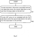
- Figure 9 is a flow chart illustrating embodiments of method steps 901-902 performed in a control node 140.
- the method aims at supporting a base station 110 in transmitting information data 300 to a terminal 120.
- the control node 140, the base station 110 and the terminal 120 are comprised within a wireless communication network 100.
- the wireless communication network 100 may further comprise a control node 140 and/or a further terminal 130.
- the information data 300 comprises a first data block 301 and a second data block 302.
- the first and second data blocks 301, 302 are arranged to be transmitted to the same terminal 120 or to different terminals 120, 130.
- the method may comprise a number of method steps 901-902.
- steps 901-902 may be performed in any arbitrary chronological order and that some of them, e.g. step 901 and step 902, or even all the two steps 901-902 may be performed simultaneously or in an altered, arbitrarily rearranged, decomposed or even completely reversed chronological order, according to different embodiments.
- the method may comprise the following steps:
- Modulation information associated with the first data block 301 and/or the second data block 302 to be sent from the base station 110 to the terminal 120 are provided.
- a first and second USF value 310, 320 associated with the first data block 301 and/or the second data block 302 to be sent from the base station 110 to the terminal 120 are provided.
- Figure 10 is a block diagram illustrating embodiments of an arrangement 1000 situated in a control node 140.
- the arrangement 1000 is configured to perform the method steps 901-902 for supporting a base station 110 in transmitting information data 300 to a terminal 120.
- the control node 140, the base station 110 and the terminal 120 are comprised within a wireless communication network 100.
- the information data 300 comprises a first data block 301 and a second data block 302.
- the arrangement 1000 comprises a first providing unit 1001.
- the first providing unit 1001 is adapted to provide modulation information associated with the first data block 301 and/or the second data block 302 to be sent from the base station 110 to the terminal 120.
- the arrangement 1000 also comprises a second providing unit 1002.
- the second providing unit 1002 is adapted to provide an USF value 310 associated with the first data block 301 and/or the second data block 302 to be sent from the base station 110 to the terminal 120.
- the first and second USF value 310, 320 are modulated together with the first data block 301 and the second data block 302. Also, the first data block 301 and the second data block 302 do not have to be sent to the same terminal 120.
- the arrangement 1000 may according to some embodiments comprise a processing unit 1020.
- the processing unit 1020 may be represented by e.g. a CPU, a processor, a microprocessor, or other processing logic that may interpret and execute instructions.
- the processing unit 1020 may perform all data processing functions for inputting, outputting, and processing of data including data buffering and device control functions, such as call processing control, user interface control, or the like.
- the method steps 901-902 in the control node 140 may be implemented through one or more processor units 1020 in the control node 140, together with computer program code for performing the functions of the present steps 901-902.
- a computer program product comprising instructions for performing the method steps 901-902 in the control node 140 for supporting a base station 110 in transmitting information data 300 to a terminal 120.
- the computer program product mentioned above may be provided for instance in the form of a data carrier carrying computer program code for performing the method steps 901-902, according to the present solution when being loaded into the processor unit 1020.
- the data carrier may be e.g. a hard disk, a CD ROM disc, a memory stick, an optical storage device, a magnetic storage device or any other appropriate medium such as a disk or tape that can hold machine readable data.
- the computer program product may furthermore be provided as computer program code on a server and downloaded to the control node 140 remotely, e.g. over an Internet or an intranet connection.
- the base station 110 and the terminal 120 are comprised within a wireless communication network 100.
- the information data 300 comprises a first data block 301 and a second data block 302.
- the first and second data blocks 301, 302 are arranged to be transmitted to the same terminal 120 or different terminals 120, 130.
- the computer program product comprises instructions for providing modulation information associated with the first data block 301 and/or the second data block 302 to be sent from the base station 110 to the terminal 120.
- the computer program product further comprises instructions for providing a first and second USF 310, 320 associated with the first data block 301 and/or the second data block 302 to be sent from the base station 110 to the terminal 120, when the computer program product is run on a processing unit 1020 comprised within the control node 140.
- the first and second USF 310, 320 are modulated together with the first data block 301 and the second data block 302. Also, the first data block 301 and the second data block 302 do not have to be intended for the same terminal 120.
Landscapes
- Engineering & Computer Science (AREA)
- Computer Networks & Wireless Communication (AREA)
- Signal Processing (AREA)
- Mobile Radio Communication Systems (AREA)
Applications Claiming Priority (2)
| Application Number | Priority Date | Filing Date | Title |
|---|---|---|---|
| US2802908P | 2008-02-12 | 2008-02-12 | |
| PCT/SE2009/050132 WO2009102270A1 (en) | 2008-02-12 | 2009-02-09 | Method and arrangement in a wireless communication network |
Publications (2)
| Publication Number | Publication Date |
|---|---|
| EP2243242A1 EP2243242A1 (en) | 2010-10-27 |
| EP2243242B1 true EP2243242B1 (en) | 2016-04-20 |
Family
ID=40719639
Family Applications (1)
| Application Number | Title | Priority Date | Filing Date |
|---|---|---|---|
| EP09710382.4A Active EP2243242B1 (en) | 2008-02-12 | 2009-02-09 | Method and arrangement in a wireless communication network |
Country Status (9)
| Country | Link |
|---|---|
| US (2) | US8724730B2 (zh) |
| EP (1) | EP2243242B1 (zh) |
| JP (1) | JP5297469B2 (zh) |
| CN (2) | CN101946440B (zh) |
| ES (1) | ES2582667T3 (zh) |
| IL (1) | IL206733A (zh) |
| RU (1) | RU2479134C2 (zh) |
| TW (1) | TWI475837B (zh) |
| WO (1) | WO2009102270A1 (zh) |
Families Citing this family (7)
| Publication number | Priority date | Publication date | Assignee | Title |
|---|---|---|---|---|
| US8724730B2 (en) * | 2008-02-12 | 2014-05-13 | Telefonaktiebolaget L M Ericsson (Publ) | Method and arrangement in a wireless communication network |
| CN101997640B (zh) * | 2009-08-26 | 2013-01-02 | 华为技术有限公司 | 一种下行分组域数据业务编码方法和装置 |
| EP2676509B1 (en) * | 2011-02-18 | 2018-10-03 | Telefonaktiebolaget LM Ericsson (publ) | Methods, mobile station and base station, for extended sharing of uplink packet data channels in a gsm network |
| CN103249149B (zh) * | 2012-02-03 | 2016-08-24 | 华为技术有限公司 | 分组数据业务下行数据块的发送、接收方法及装置 |
| JP6314238B2 (ja) * | 2014-01-24 | 2018-04-18 | 華為技術有限公司Huawei Technologies Co.,Ltd. | ダウンリンクパラメータを決定するための方法、デバイス、及び装置 |
| EP3912290A4 (en) | 2019-01-17 | 2022-01-26 | ZTE Corporation | CONFLICT-BASED PAYLOAD TRANSMISSIONS USING DIFFERENTIAL ENCODING |
| CN110932930B (zh) * | 2019-11-13 | 2021-08-10 | 苏州浪潮智能科技有限公司 | 一种服务器pcie链路稳定性的检测方法、装置及介质 |
Family Cites Families (19)
| Publication number | Priority date | Publication date | Assignee | Title |
|---|---|---|---|---|
| DE69833199T2 (de) * | 1997-08-01 | 2006-09-07 | Ntt Mobile Communications Network Inc. | Datenfolgegenerator, sender, informationsdatendekoder, empfänger, sender-empfänger, datenfolgegenerationsverfahren, informationsdatendekodierungsverfahren, und aufzeichnungsmedium |
| FI105516B (fi) | 1998-07-24 | 2000-08-31 | Nokia Networks Oy | Menetelmä ja pakettiradiojärjestelmä modulaatio- ja signalointitiedon siirtämiseksi |
| US6956836B2 (en) * | 2001-05-17 | 2005-10-18 | Ericsson, Inc. | Asymmetric frequency allocation for packet channels in a wireless network |
| US7149245B2 (en) * | 2002-04-29 | 2006-12-12 | Lucent Technologies Inc. | Link adaption in enhanced general packet radio service networks |
| EP1431919B1 (en) * | 2002-12-05 | 2010-03-03 | Samsung Electronics Co., Ltd. | Method and apparatus for encoding and decoding three-dimensional object data by using octrees |
| KR100513732B1 (ko) | 2002-12-05 | 2005-09-08 | 삼성전자주식회사 | 3차원 객체 데이터 부호화 및 복호화 방법 및 장치 |
| JP4885456B2 (ja) | 2003-03-03 | 2012-02-29 | ノキア コーポレイション | ブロードバンド信号で搬送されるトランスポートストリーム用の階層的モードを指示する方法、システムおよびネットワークエンティティ |
| RU2341910C2 (ru) | 2003-03-03 | 2008-12-20 | Нокиа Корпорейшн | Способ, система и сетевой объект для указания иерархического режима для транспортных потоков, переносимых при широкополосной передаче |
| US7342956B2 (en) | 2003-06-16 | 2008-03-11 | Broadcom Corporation | System and method to extract uplink status flag bits in a cellular wireless network |
| US7724701B2 (en) * | 2003-09-30 | 2010-05-25 | Qualcomm Incorporated | Method and apparatus for controlling reverse link data rate of a mobile station in a communication system with reverse link common rate control |
| JP2008523709A (ja) * | 2004-12-13 | 2008-07-03 | テレフオンアクチーボラゲット エル エム エリクソン(パブル) | アップリンク無線通信チャンネル設定時の待ち時間の短縮 |
| JP2007221178A (ja) * | 2005-04-01 | 2007-08-30 | Ntt Docomo Inc | 送信装置及び送信方法 |
| US7567791B2 (en) * | 2005-09-19 | 2009-07-28 | Qualcomm Incorporated | Wireless terminal methods and apparatus for use in a wireless communications system that uses a multi-mode base station |
| WO2007053069A1 (en) * | 2005-11-01 | 2007-05-10 | Telefonaktiebolaget Lm Ericsson (Publ) | Method and arrangements in a radio communication system |
| EP1835670A1 (en) | 2006-03-14 | 2007-09-19 | Siemens S.p.A. | Coexistence of legacy GPRS/EGPRS radio blocks and reduced transmit time interval (RTTI) radio blocks |
| CN101043299B (zh) * | 2006-04-05 | 2010-08-25 | 华为技术有限公司 | 一种ack/nack方法 |
| CN100574291C (zh) * | 2006-05-10 | 2009-12-23 | 威盛电子股份有限公司 | 盲调制制式检测方法和装置及解码方法和装置 |
| WO2008115114A2 (en) * | 2007-03-16 | 2008-09-25 | Telefonaktiebolaget Lm Ericsson (Publ) | Detecting the presence of coding scheme cs-i rlc/mac control message |
| US8724730B2 (en) | 2008-02-12 | 2014-05-13 | Telefonaktiebolaget L M Ericsson (Publ) | Method and arrangement in a wireless communication network |
-
2009
- 2009-02-09 US US12/866,686 patent/US8724730B2/en active Active
- 2009-02-09 EP EP09710382.4A patent/EP2243242B1/en active Active
- 2009-02-09 CN CN200980104937.0A patent/CN101946440B/zh active Active
- 2009-02-09 CN CN201410453196.XA patent/CN104253670B/zh active Active
- 2009-02-09 RU RU2010137826/08A patent/RU2479134C2/ru active
- 2009-02-09 WO PCT/SE2009/050132 patent/WO2009102270A1/en active Application Filing
- 2009-02-09 JP JP2010545832A patent/JP5297469B2/ja active Active
- 2009-02-09 ES ES09710382.4T patent/ES2582667T3/es active Active
- 2009-02-11 TW TW098104348A patent/TWI475837B/zh active
-
2010
- 2010-06-30 IL IL206733A patent/IL206733A/en active IP Right Grant
-
2014
- 2014-03-31 US US14/230,082 patent/US9113452B2/en active Active
Also Published As
| Publication number | Publication date |
|---|---|
| RU2010137826A (ru) | 2012-03-20 |
| TW200947930A (en) | 2009-11-16 |
| IL206733A (en) | 2015-08-31 |
| US20140211719A1 (en) | 2014-07-31 |
| CN104253670B (zh) | 2018-04-10 |
| IL206733A0 (en) | 2010-12-30 |
| RU2479134C2 (ru) | 2013-04-10 |
| US8724730B2 (en) | 2014-05-13 |
| US9113452B2 (en) | 2015-08-18 |
| EP2243242A1 (en) | 2010-10-27 |
| US20100322338A1 (en) | 2010-12-23 |
| WO2009102270A1 (en) | 2009-08-20 |
| ES2582667T3 (es) | 2016-09-14 |
| CN101946440B (zh) | 2014-10-01 |
| JP2011512095A (ja) | 2011-04-14 |
| JP5297469B2 (ja) | 2013-09-25 |
| TWI475837B (zh) | 2015-03-01 |
| CN101946440A (zh) | 2011-01-12 |
| CN104253670A (zh) | 2014-12-31 |
Similar Documents
| Publication | Publication Date | Title |
|---|---|---|
| US9113452B2 (en) | Method and arrangement in a wireless communication network | |
| KR101603672B1 (ko) | 다중 무선 통신 디바이스 확인응답들 | |
| JP2019080319A (ja) | 複数のチャネル品質情報値を構成するための、無線ノード、ワイヤレスデバイス及びそれらにおける方法 | |
| US9591459B2 (en) | Signaling whether a network has broadcast system information | |
| CN112134649B (zh) | 传输数据的方法和发送端设备 | |
| US11606239B2 (en) | Non-coherent waveforms for wireless communication | |
| US10361893B2 (en) | Radio network node, wireless device and methods thereof using GMSK modulation applying negative modulation index | |
| CN109803408B (zh) | 信道状态信息报告的传输方法及通信设备 | |
| CN111435859B (zh) | 发送、接收方法及装置 | |
| CN112399436A (zh) | 接收、发送下行控制信息的方法和装置 | |
| CN106793112B (zh) | Mcs信息指示方法、mcs信息指示装置、基站及终端 | |
| CN108604947B (zh) | 用于管理有关由无线设备在下行链路中接收的信号质量和/或信号强度的信息的方法和装置 | |
| US9025482B2 (en) | Quantitative interference detection | |
| US20210306122A1 (en) | Demodulation reference signal sharing pattern selection in a wireless communication system | |
| CN109417789B (zh) | 子帧指示方法及设备 |
Legal Events
| Date | Code | Title | Description |
|---|---|---|---|
| PUAI | Public reference made under article 153(3) epc to a published international application that has entered the european phase |
Free format text: ORIGINAL CODE: 0009012 |
|
| 17P | Request for examination filed |
Effective date: 20100629 |
|
| AK | Designated contracting states |
Kind code of ref document: A1 Designated state(s): AT BE BG CH CY CZ DE DK EE ES FI FR GB GR HR HU IE IS IT LI LT LU LV MC MK MT NL NO PL PT RO SE SI SK TR |
|
| AX | Request for extension of the european patent |
Extension state: AL BA RS |
|
| RIN1 | Information on inventor provided before grant (corrected) |
Inventor name: ERIKSSON, STEFAN Inventor name: SUNDBERG, MARTEN Inventor name: AXELSSON, HAKAN Inventor name: MALM, ANDERS |
|
| DAX | Request for extension of the european patent (deleted) | ||
| 17Q | First examination report despatched |
Effective date: 20110616 |
|
| GRAP | Despatch of communication of intention to grant a patent |
Free format text: ORIGINAL CODE: EPIDOSNIGR1 |
|
| INTG | Intention to grant announced |
Effective date: 20151207 |
|
| RIN1 | Information on inventor provided before grant (corrected) |
Inventor name: MALM, ANDERS Inventor name: AXELSSON, HAKAN Inventor name: ERIKSSON, STEFAN Inventor name: SUNDBERG, MARTEN |
|
| GRAS | Grant fee paid |
Free format text: ORIGINAL CODE: EPIDOSNIGR3 |
|
| GRAA | (expected) grant |
Free format text: ORIGINAL CODE: 0009210 |
|
| AK | Designated contracting states |
Kind code of ref document: B1 Designated state(s): AT BE BG CH CY CZ DE DK EE ES FI FR GB GR HR HU IE IS IT LI LT LU LV MC MK MT NL NO PL PT RO SE SI SK TR |
|
| REG | Reference to a national code |
Ref country code: GB Ref legal event code: FG4D |
|
| REG | Reference to a national code |
Ref country code: CH Ref legal event code: EP |
|
| REG | Reference to a national code |
Ref country code: AT Ref legal event code: REF Ref document number: 793460 Country of ref document: AT Kind code of ref document: T Effective date: 20160515 |
|
| REG | Reference to a national code |
Ref country code: IE Ref legal event code: FG4D |
|
| REG | Reference to a national code |
Ref country code: DE Ref legal event code: R096 Ref document number: 602009037932 Country of ref document: DE |
|
| REG | Reference to a national code |
Ref country code: NL Ref legal event code: FP |
|
| REG | Reference to a national code |
Ref country code: LT Ref legal event code: MG4D |
|
| REG | Reference to a national code |
Ref country code: ES Ref legal event code: FG2A Ref document number: 2582667 Country of ref document: ES Kind code of ref document: T3 Effective date: 20160914 |
|
| REG | Reference to a national code |
Ref country code: AT Ref legal event code: MK05 Ref document number: 793460 Country of ref document: AT Kind code of ref document: T Effective date: 20160420 |
|
| PG25 | Lapsed in a contracting state [announced via postgrant information from national office to epo] |
Ref country code: LT Free format text: LAPSE BECAUSE OF FAILURE TO SUBMIT A TRANSLATION OF THE DESCRIPTION OR TO PAY THE FEE WITHIN THE PRESCRIBED TIME-LIMIT Effective date: 20160420 Ref country code: PL Free format text: LAPSE BECAUSE OF FAILURE TO SUBMIT A TRANSLATION OF THE DESCRIPTION OR TO PAY THE FEE WITHIN THE PRESCRIBED TIME-LIMIT Effective date: 20160420 Ref country code: FI Free format text: LAPSE BECAUSE OF FAILURE TO SUBMIT A TRANSLATION OF THE DESCRIPTION OR TO PAY THE FEE WITHIN THE PRESCRIBED TIME-LIMIT Effective date: 20160420 Ref country code: NO Free format text: LAPSE BECAUSE OF FAILURE TO SUBMIT A TRANSLATION OF THE DESCRIPTION OR TO PAY THE FEE WITHIN THE PRESCRIBED TIME-LIMIT Effective date: 20160720 |
|
| PG25 | Lapsed in a contracting state [announced via postgrant information from national office to epo] |
Ref country code: HR Free format text: LAPSE BECAUSE OF FAILURE TO SUBMIT A TRANSLATION OF THE DESCRIPTION OR TO PAY THE FEE WITHIN THE PRESCRIBED TIME-LIMIT Effective date: 20160420 Ref country code: SE Free format text: LAPSE BECAUSE OF FAILURE TO SUBMIT A TRANSLATION OF THE DESCRIPTION OR TO PAY THE FEE WITHIN THE PRESCRIBED TIME-LIMIT Effective date: 20160420 Ref country code: LV Free format text: LAPSE BECAUSE OF FAILURE TO SUBMIT A TRANSLATION OF THE DESCRIPTION OR TO PAY THE FEE WITHIN THE PRESCRIBED TIME-LIMIT Effective date: 20160420 Ref country code: AT Free format text: LAPSE BECAUSE OF FAILURE TO SUBMIT A TRANSLATION OF THE DESCRIPTION OR TO PAY THE FEE WITHIN THE PRESCRIBED TIME-LIMIT Effective date: 20160420 Ref country code: PT Free format text: LAPSE BECAUSE OF FAILURE TO SUBMIT A TRANSLATION OF THE DESCRIPTION OR TO PAY THE FEE WITHIN THE PRESCRIBED TIME-LIMIT Effective date: 20160822 Ref country code: GR Free format text: LAPSE BECAUSE OF FAILURE TO SUBMIT A TRANSLATION OF THE DESCRIPTION OR TO PAY THE FEE WITHIN THE PRESCRIBED TIME-LIMIT Effective date: 20160721 |
|
| PG25 | Lapsed in a contracting state [announced via postgrant information from national office to epo] |
Ref country code: IT Free format text: LAPSE BECAUSE OF FAILURE TO SUBMIT A TRANSLATION OF THE DESCRIPTION OR TO PAY THE FEE WITHIN THE PRESCRIBED TIME-LIMIT Effective date: 20160420 Ref country code: BE Free format text: LAPSE BECAUSE OF FAILURE TO SUBMIT A TRANSLATION OF THE DESCRIPTION OR TO PAY THE FEE WITHIN THE PRESCRIBED TIME-LIMIT Effective date: 20160420 |
|
| REG | Reference to a national code |
Ref country code: DE Ref legal event code: R097 Ref document number: 602009037932 Country of ref document: DE |
|
| PG25 | Lapsed in a contracting state [announced via postgrant information from national office to epo] |
Ref country code: CZ Free format text: LAPSE BECAUSE OF FAILURE TO SUBMIT A TRANSLATION OF THE DESCRIPTION OR TO PAY THE FEE WITHIN THE PRESCRIBED TIME-LIMIT Effective date: 20160420 Ref country code: EE Free format text: LAPSE BECAUSE OF FAILURE TO SUBMIT A TRANSLATION OF THE DESCRIPTION OR TO PAY THE FEE WITHIN THE PRESCRIBED TIME-LIMIT Effective date: 20160420 Ref country code: SK Free format text: LAPSE BECAUSE OF FAILURE TO SUBMIT A TRANSLATION OF THE DESCRIPTION OR TO PAY THE FEE WITHIN THE PRESCRIBED TIME-LIMIT Effective date: 20160420 Ref country code: RO Free format text: LAPSE BECAUSE OF FAILURE TO SUBMIT A TRANSLATION OF THE DESCRIPTION OR TO PAY THE FEE WITHIN THE PRESCRIBED TIME-LIMIT Effective date: 20160420 Ref country code: DK Free format text: LAPSE BECAUSE OF FAILURE TO SUBMIT A TRANSLATION OF THE DESCRIPTION OR TO PAY THE FEE WITHIN THE PRESCRIBED TIME-LIMIT Effective date: 20160420 |
|
| REG | Reference to a national code |
Ref country code: FR Ref legal event code: PLFP Year of fee payment: 9 |
|
| PLBE | No opposition filed within time limit |
Free format text: ORIGINAL CODE: 0009261 |
|
| STAA | Information on the status of an ep patent application or granted ep patent |
Free format text: STATUS: NO OPPOSITION FILED WITHIN TIME LIMIT |
|
| 26N | No opposition filed |
Effective date: 20170123 |
|
| PG25 | Lapsed in a contracting state [announced via postgrant information from national office to epo] |
Ref country code: SI Free format text: LAPSE BECAUSE OF FAILURE TO SUBMIT A TRANSLATION OF THE DESCRIPTION OR TO PAY THE FEE WITHIN THE PRESCRIBED TIME-LIMIT Effective date: 20160420 |
|
| PG25 | Lapsed in a contracting state [announced via postgrant information from national office to epo] |
Ref country code: MC Free format text: LAPSE BECAUSE OF FAILURE TO SUBMIT A TRANSLATION OF THE DESCRIPTION OR TO PAY THE FEE WITHIN THE PRESCRIBED TIME-LIMIT Effective date: 20160420 |
|
| REG | Reference to a national code |
Ref country code: CH Ref legal event code: PL |
|
| PG25 | Lapsed in a contracting state [announced via postgrant information from national office to epo] |
Ref country code: CH Free format text: LAPSE BECAUSE OF NON-PAYMENT OF DUE FEES Effective date: 20170228 Ref country code: LI Free format text: LAPSE BECAUSE OF NON-PAYMENT OF DUE FEES Effective date: 20170228 |
|
| PG25 | Lapsed in a contracting state [announced via postgrant information from national office to epo] |
Ref country code: LU Free format text: LAPSE BECAUSE OF NON-PAYMENT OF DUE FEES Effective date: 20170209 |
|
| REG | Reference to a national code |
Ref country code: FR Ref legal event code: PLFP Year of fee payment: 10 |
|
| PG25 | Lapsed in a contracting state [announced via postgrant information from national office to epo] |
Ref country code: MT Free format text: LAPSE BECAUSE OF NON-PAYMENT OF DUE FEES Effective date: 20170209 |
|
| PG25 | Lapsed in a contracting state [announced via postgrant information from national office to epo] |
Ref country code: HU Free format text: LAPSE BECAUSE OF FAILURE TO SUBMIT A TRANSLATION OF THE DESCRIPTION OR TO PAY THE FEE WITHIN THE PRESCRIBED TIME-LIMIT; INVALID AB INITIO Effective date: 20090209 |
|
| PG25 | Lapsed in a contracting state [announced via postgrant information from national office to epo] |
Ref country code: BG Free format text: LAPSE BECAUSE OF FAILURE TO SUBMIT A TRANSLATION OF THE DESCRIPTION OR TO PAY THE FEE WITHIN THE PRESCRIBED TIME-LIMIT Effective date: 20160420 |
|
| PG25 | Lapsed in a contracting state [announced via postgrant information from national office to epo] |
Ref country code: CY Free format text: LAPSE BECAUSE OF NON-PAYMENT OF DUE FEES Effective date: 20160420 |
|
| PG25 | Lapsed in a contracting state [announced via postgrant information from national office to epo] |
Ref country code: MK Free format text: LAPSE BECAUSE OF FAILURE TO SUBMIT A TRANSLATION OF THE DESCRIPTION OR TO PAY THE FEE WITHIN THE PRESCRIBED TIME-LIMIT Effective date: 20160420 |
|
| PG25 | Lapsed in a contracting state [announced via postgrant information from national office to epo] |
Ref country code: TR Free format text: LAPSE BECAUSE OF FAILURE TO SUBMIT A TRANSLATION OF THE DESCRIPTION OR TO PAY THE FEE WITHIN THE PRESCRIBED TIME-LIMIT Effective date: 20160420 |
|
| PG25 | Lapsed in a contracting state [announced via postgrant information from national office to epo] |
Ref country code: IS Free format text: LAPSE BECAUSE OF FAILURE TO SUBMIT A TRANSLATION OF THE DESCRIPTION OR TO PAY THE FEE WITHIN THE PRESCRIBED TIME-LIMIT Effective date: 20160820 |
|
| PGFP | Annual fee paid to national office [announced via postgrant information from national office to epo] |
Ref country code: FR Payment date: 20230223 Year of fee payment: 15 |
|
| PGFP | Annual fee paid to national office [announced via postgrant information from national office to epo] |
Ref country code: NL Payment date: 20240226 Year of fee payment: 16 Ref country code: ES Payment date: 20240301 Year of fee payment: 16 Ref country code: IE Payment date: 20240227 Year of fee payment: 16 |
|
| PGFP | Annual fee paid to national office [announced via postgrant information from national office to epo] |
Ref country code: DE Payment date: 20240228 Year of fee payment: 16 Ref country code: GB Payment date: 20240227 Year of fee payment: 16 |