EP2243237B1 - Wellenlängen multiplexendes modul - Google Patents
Wellenlängen multiplexendes modul Download PDFInfo
- Publication number
- EP2243237B1 EP2243237B1 EP09706377.0A EP09706377A EP2243237B1 EP 2243237 B1 EP2243237 B1 EP 2243237B1 EP 09706377 A EP09706377 A EP 09706377A EP 2243237 B1 EP2243237 B1 EP 2243237B1
- Authority
- EP
- European Patent Office
- Prior art keywords
- module
- fiber optic
- housing
- optical
- splitter
- Prior art date
- Legal status (The legal status is an assumption and is not a legal conclusion. Google has not performed a legal analysis and makes no representation as to the accuracy of the status listed.)
- Not-in-force
Links
- 239000000835 fiber Substances 0.000 claims description 112
- 230000003287 optical effect Effects 0.000 claims description 57
- 238000003780 insertion Methods 0.000 claims description 3
- 230000037431 insertion Effects 0.000 claims description 3
- 238000010586 diagram Methods 0.000 description 9
- 230000005540 biological transmission Effects 0.000 description 8
- 238000009434 installation Methods 0.000 description 6
- 238000005516 engineering process Methods 0.000 description 5
- 230000000295 complement effect Effects 0.000 description 2
- 239000000945 filler Substances 0.000 description 2
- 239000013307 optical fiber Substances 0.000 description 2
- 239000004593 Epoxy Substances 0.000 description 1
- 230000000712 assembly Effects 0.000 description 1
- 238000000429 assembly Methods 0.000 description 1
- 230000007175 bidirectional communication Effects 0.000 description 1
- 238000004140 cleaning Methods 0.000 description 1
- 230000006854 communication Effects 0.000 description 1
- 238000002955 isolation Methods 0.000 description 1
Images









Classifications
-
- G—PHYSICS
- G02—OPTICS
- G02B—OPTICAL ELEMENTS, SYSTEMS OR APPARATUS
- G02B6/00—Light guides; Structural details of arrangements comprising light guides and other optical elements, e.g. couplings
- G02B6/44—Mechanical structures for providing tensile strength and external protection for fibres, e.g. optical transmission cables
- G02B6/4439—Auxiliary devices
- G02B6/444—Systems or boxes with surplus lengths
- G02B6/4452—Distribution frames
- G02B6/44524—Distribution frames with frame parts or auxiliary devices mounted on the frame and collectively not covering a whole width of the frame or rack
-
- G—PHYSICS
- G02—OPTICS
- G02B—OPTICAL ELEMENTS, SYSTEMS OR APPARATUS
- G02B6/00—Light guides; Structural details of arrangements comprising light guides and other optical elements, e.g. couplings
- G02B6/44—Mechanical structures for providing tensile strength and external protection for fibres, e.g. optical transmission cables
- G02B6/4439—Auxiliary devices
- G02B6/444—Systems or boxes with surplus lengths
- G02B6/44528—Patch-cords; Connector arrangements in the system or in the box
-
- G—PHYSICS
- G02—OPTICS
- G02B—OPTICAL ELEMENTS, SYSTEMS OR APPARATUS
- G02B6/00—Light guides; Structural details of arrangements comprising light guides and other optical elements, e.g. couplings
- G02B6/44—Mechanical structures for providing tensile strength and external protection for fibres, e.g. optical transmission cables
- G02B6/4439—Auxiliary devices
- G02B6/444—Systems or boxes with surplus lengths
- G02B6/4453—Cassettes
- G02B6/4455—Cassettes characterised by the way of extraction or insertion of the cassette in the distribution frame, e.g. pivoting, sliding, rotating or gliding
-
- H—ELECTRICITY
- H04—ELECTRIC COMMUNICATION TECHNIQUE
- H04J—MULTIPLEX COMMUNICATION
- H04J14/00—Optical multiplex systems
- H04J14/02—Wavelength-division multiplex systems
- H04J14/0201—Add-and-drop multiplexing
- H04J14/0202—Arrangements therefor
- H04J14/0205—Select and combine arrangements, e.g. with an optical combiner at the output after adding or dropping
-
- H—ELECTRICITY
- H04—ELECTRIC COMMUNICATION TECHNIQUE
- H04J—MULTIPLEX COMMUNICATION
- H04J14/00—Optical multiplex systems
- H04J14/02—Wavelength-division multiplex systems
- H04J14/03—WDM arrangements
- H04J14/0307—Multiplexers; Demultiplexers
-
- H—ELECTRICITY
- H04—ELECTRIC COMMUNICATION TECHNIQUE
- H04J—MULTIPLEX COMMUNICATION
- H04J14/00—Optical multiplex systems
- H04J14/02—Wavelength-division multiplex systems
- H04J14/0201—Add-and-drop multiplexing
Definitions
- the present disclosure generally relates to fiber optic telecommunications equipment. More specifically, the present disclosure relates to modules for housing fiber optic telecommunications equipment.
- modules including splitters or fanouts are used to provide the connection between transmission fibers and customer fibers.
- a module mounting chassis capable of mounting multiple modules may be used in such an installation.
- chassis may accept several modules, the initial installation may only include fewer modules mounted in the chassis, of enough to serve current needs.
- These chassis may be configured with limited access to onc of more sides, or may be mounted in cramped locations.
- some of these chassis may be pre-configured with the maximum capacity of transmission cables to accommodate and link to modules which may be installed in the future. Since it is desirable to have access to components within the chassis for cleaning during the installation of a new module, some provision or feature of the chassis will desirably permit a user to access and dean the connectors of these pre-connectorized and pre-installed transmission cables.
- chassis pre-connectorized and pre-installed transmission cables.
- Wavelength division multiplexing is a technology which multiplexes multiple optical carrier signals on a single optical fiber by using different wavelengths of laser light to carry different signals. This allows for a multiplication in capacity, in addition to making it possible to perform bidirectional communications over one strand of fiber.
- a WDM system uses a multiplexer at the transmitter to join signals together and a demultiplexer at the receiver to split them apart With the right type of fiber, it is possible to have a device that does both simultaneously, and can function as an optical add-drop multiplexer. WDM systems allow expansion of the capacity of the network without laying more fiber.
- WDM systems are divided in different wavelength patterns: 1) conventional WDM; 2) dense WDM (DWDM); and 3) coarse WDM (CWDM).
- WDM, DWDM and CWDM are based on the same concept of using multiple wavelengths of light on a single fiber, but differ in the spacing of the wavelengths, number of channels, and the ability to amplify the multiplexed signals in the optical space.
- EP 1 657 953 A discloses an optical transmission apparatus that includes a plurality of wavelength selection switches that receive optical input signals and are cross-connected to a corresponding plurality of multiplexers. The output of the multiplexers can therefore be selected from any of the input transmission paths, or from an added signal path- EP 1 657 953 A lacks a fiber optic splitter or add/drop filters, and does not disclose any particular physical arrangement or orientation of optical circuitry elements.
- WO 00/41430 A discloses an optical cross connect system that uses input demultiplexers to split signals according to wavelength (X1, 7 ⁇ 2), which are then passed to an add drop module, and from the add drop module to output multiplexers.
- WO 00/41430 A lacks an optical splitter altogether, and does not combine signals at the add/drop module.
- WO 00/41430 A does not disclose any particular physical arrangement or orientation of optical circuitry elements.
- US 2008/013954 A discloses an optical add/drop multiplexer/demultiplexer arrangement.
- US 2008/013954 A lacks both an optical splitter and an add drop module altogether, and also does not disclose any particular physical arrangement or orientation of optical circuitry elements.
- US 2006/171717 A1 discloses an optical add/drop multiplexer that includes optical switches to allow control of demultiplexed signals.
- US 2006/171717 A1 is used to provide backup routing of optical signals through such an optical add-drop multiplexer in case of signal failures; it does not disclose either the optical splitter or separate add drop module, and also does not disclose any particular physical arrangement or orientation of optical circuitry elements.
- wavelength division multiplexing technology In certain telecommunications applications, it might be desirable to combine wavelength division multiplexing technology with fiber optic signal splitting technology.
- the present invention relates to telecommunications equipment that combines wavelength division multiplexing technology and fiber optic signal splitting technology and packages it in a modular format
- the module of the present invention as defined by claim 1 includes an input for inputting a fiber optic signal to be split into multiple strands, an input for inputting a fiber optic signal to be demultiplexed into different wavelengths of lasedight, and an output for outputting a combination signal wherein a split signal and a demultiplexed wavelength are combined into a single output fiber.
- the module includes within the interior an optical multiplexer/demultiplexer, a fiber optic splitter, and an optical device for combining a split signal and a demultiplexed wavelength into an output fiber.
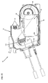
- FIGS. 1-4 illustrate a telecommunications module 10 having features that are examples of inventive aspects in accordance with the present disclosure.
- the telecommunications module 10 may also be referred to herein as a fiber optic wavelength division multiplexing (WDM) module 10.
- the WDM module 10 is configured to be inserted within a telecommunications chassis similar to the chassis shown and described in commonly-owned U.S. Patent Application Ser. No. 11/975,905 (filed October 22, 2007 , entitled WAVELENGTH DIVISION MULTIPLEXING NODULE).
- the WDM module 10 is also configured to be inserted into the telecommunications chassis in a similar manner to that shown and described in the U.S. Patent Application Ser. No. 11/975,905 .
- the WDM module 10 of the present disclosure is configured to power split an input signal into a plurality of signals.
- the WDM module 10 is also configured to demultiplex a second input signal into a plurality of wavelengths.
- An optical device 22 e.g., an optical add/drop filter, a single channel filter, etc.
- within the module 10 is configured to combine one of the power split signals and one of the demultiplexed wavelengths into a combination output signal that is output through the module 10.
- the powersplitting function, the demultiplexing function and the signal combination function are all performed within the module 10.
- WDM module 10 is shown in an exploded orientation.
- WDM module 10 includes a module housing 12 that includes a main housing portion 14 and a removable cover 16.
- the module housing 12 including the main housing portion 14 and the removable cover 16 is illustrated separately in FIG. 5 , without the internal components of the module 10.
- the WDM module 10 is configured to house a fiber optic splitter 18, a multiplexer/demultiplexer chip 20, and a plurality of optical devices 22 configured to combine a split signal and a demultiplexed wavelength into a single output signal.
- the optical devices 22 that are configured to combine a split signal and a demultiplexed wavelength into a single output signal may be optical add/drop filters.
- Optical add/drop filters and their uses are known in the art.
- the optical add/drop filters may also be called single channel filters. Other types of devices performing the same function are possible.
- the fiber optic splitter 18 is adapted to power split a first input fiber optic signal entering the module 10 into multiple strands.
- the multiplexer/demultiplexer chip 20 is configured to demultiplex a second input fiber optic signal entering the module 10 into different wavelengths of laserlight.
- Each of the optical devices 22 e.g., add/drop filters
- Each of the combination signals are then output from the module 10.
- the fiber optic splitter 18 is a 1x8 splitter and the multiplexer/demultiplexer 20 is an 8-channel chip. Accordingly, in the embodiment of the module 10 shown, 1 splitter input signal and 1 multiplexer input signal get output as 8 separate combination signals.
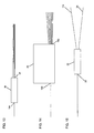
- FIG. 12 A fiber optic circuit diagram of the WDM module 10 of FIGS. 1-4 is shown in FIG. 12 .
- FIG. 13 diagrammatically illustrates the fiber optic splitter 18 configured for use in the WDM module 10.
- FIG. 14 diagrammatically illustrates the multiplexer chip 20 configured for use in the WDM module 10.
- FIG. 15 diagrammatically illustrates one of the add/drop filters 22 configured for use in the WDM module 10 of FIG. 1 , wherein the add/drop filter 22 is configured to combine a split signal and a demultiplexed wavelength into an output signal.
- a signal input into the fiber optic splitter 18 gets split into 8 separate signals, each separate signal being the same as the original input signal. It should be noted that in other embodiments, the fiber optic splitter 18 may power split the signal into different power levels, rather than into the same signal. From an output 24 of the splitter 18, each of the split signals get spliced into an input 26 (i.e., PASS leg) of each of the add/drop filters 22. Likewise, a signal input into the multiplexer chip 20 gets demultiplexed into 8 different wavelengths.
- Each wavelength gets output from the multiplexer chip 20 as a separate signal and is spliced into another input 28 (i.e., REF leg) of the each of the add/drop filters 22.
- the signals from the splitter 18 and the multiplexer chip 20 are combined at the add/drop filters 22 and output from the add/drop filters 22 (e.g., at COM leg) as 8 combination signals.
- FIG. 2 illustrates the WDM module 10 with the two input signal cables 30, 32 going into the module 10 and the eight combination output signal cables (each one designated as "34") coming out.
- the input cables 30, 32 and the output cables 34 may be connectorized and be forwarded on to appropriate locations through fiber optic adapters 36.
- the module housing 12 includes a cable exit 38 for outputting the combination fiber optic signals out of the module 10 and to customers.
- the WDM module 10 includes a number of cable management/routing features for correctly orienting the cables within the module 10, as will be described in further detail below.
- One such feature is a splice holder/cable management structure 40 that is configured to house the plurality of fiber optic splices 42 within the module 10 and also route fiber optic cables through the module 10 (shown in further detail in FIGS. 6-8 ).
- Another cable routing feature is a cable management structure 44.
- the cable management structure is shown located between the fiber optic splitter 18 and the add/drop filters 22 (shown in further detail in FIGS. 9-11 ).
- the cable management structure 44 could be located between the fiber optic splitter 18 and the bottom wall 54 of the module 10.
- a fiber retainer 46 that is removably mounted to the main housing portion 14 of the module housing 12 is also shown in FIG. 1 . The fiber retainer 46 helps keep cables spooled around a first radius limiter 48 within the main housing 14 of the module 10.
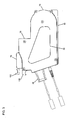
- FIGS. 2-4 illustrate the module 10 in a fully assembled configuration with the cover 16 mounted on the main housing portion 14.
- FIG. 5 illustrates the housing 12 of the module 10 in isolation, with the internal features of the module 10 removed therefrom.
- the main housing portion 14 defines a first sidewall 50 extending between a top wall 52, a bottom wall 54, a rear wall 56, and a front wall 58.
- Removable cover 16 defines a second sidewall 60 of the module housing 12 and closes off an open side 62 of the module main housing portion 14.
- Cover 16 is mounted to main housing portion 14 by fasteners through fastener holes 64 in the cover 16 and fastener mounts 66 defined on main housing portion 14.
- the cover 16 may include a label 68 placed thereon with indicia relating to the module 10 (see FIGS. 1 and 3 ).
- the main housing portion 14 defines a top mounting flange 70 and a bottom mounting flange 72 of the WDM module 10 extending from the top and bottom walls 52, 54, respectively.
- the WDM module 10 of the present application is configured for insertion into a chassis similar to the one described in U.S. Patent Application Ser. No. 11/975,905 and in a similar manner to that described therein.
- the bottom flange 72 and a corresponding slot on the chassis are smaller in size than top flange 70 and the corresponding top slot on the chassis.
- Bottom slot of the chassis is sized such that, while bottom flange 72 fits into the bottom slot of the chassis, the larger top flange 70 does not fit. This ensures that the WDM module 10 is positioned within a front opening of a chassis in a particular desired orientation to correctly position the cable inputs and the outputs relative to the chassis.
- the housing 12 of the WDM module 10 of the present application is configured similarly to those of the modules shown in described in U.S. Patent Application Ser. No. 11/975,905 for mounting purposes, the WDM module 10 of the present application has certain differences.
- the WDM module housing 12 of the present application has the depth of two of the modules of U.S. Patent Application Ser. No. 11/975,905 .
- the WDM module 10 of the present application occupies two mounting locations within a chassis such as the chassis shown in U.S. Patent Application Ser. No. 11/975,905 .
- the rear wall 56 of main housing portion 14 includes a curved portion 74 configured to provide bend radius protection to cables within interior of the module 10. Similar to modules of U.S. Patent Application Ser. No. 11/975,905 , the rear wall 56 of main housing 14 includes an inset portion 76. The inset portion 76 might be used to accommodate a pair of fiber optic connectors protruding out of the rear wall 56, if, for example, a rear input configuration is desired instead of a front input configuration. It should be noted that in the depicted embodiment, the WDM module 10 includes a front input configuration. Thus, the slots 78 for receiving fiber optic connectors at the rear wall 56 may be covered with inserts 80 (see FIG. 5 ). In U.S.
- the modules are shown with a rear input configuration wherein rear fiber optic connectors protrude from the rear wall at the inset portion of the module housing.
- a rear input configuration is certainly one option for the WDM module 10 of the present application.
- fiber optic connectors protruding rearwardly from rear wall 56 would mate with fiber optic adapters of adapter assemblies that are mounted within the chassis.
- the input connections 82, 84 are provided at the front of the module main housing 14.
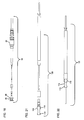
- FIG. 16 illustrates an exploded view of an input connection 82 for 20inputting a signal into the splitter 18 of the WDM module 10 and
- FIG. 17 illustrates the input connection 82 of FIG. 16 in a fully assembled configuration.
- FIG. 19 is a diagram illustrating the input connection 82 with the fiber optic splitter 18 configured for use in the WDM module 10.
- FIG. 18 illustrates a fully assembled view of the input connection 84 for inputting a signal into the multiplexer chip 20 of the WDM module 10 to be demultiplexed into different wavelengths of laserlight.
- FIG. 20 is a diagram illustrating the input connection 84 with the multiplexer chip 20 configured for use in the WDM module 10. As shown in FIGS. 16-20 , each input connection 82, 84 (whether for the fiber optic splitter 18 or the multiplexer chip 20) includes a boot 86 that mates with a crimp element 88. The crimp element 88 defines a circumferential notch 90 (i.e., recessed portion).
- the circumferential notch 90 is slidably inserted into a slot 92 defined an an insert piece 59 that is fastened to the front wall 58 of the main housing portion 14 with fasteners (see FIGS. 1 and 5 ).
- the crimp elements 88 of the input connections 82, 84 are captured by the cover 16 when the cover 16 is mounted on the main housing 14.
- the embodiment of the WDM module 10 illustrated includes the cable exit 38 at the front of module main housing 14 (see FIG. 1 ).
- the cable exit 38 is slidably mounted to main housing 14 of the WDM module 10 and is captured by the cover 16 when cover 16 is mounted to main housing 14.
- the cable exit 38 defines a protruding rear lip 94 that is slidably inserted into a slot 96 defined around a front aperture 98 defined at the front wall 58 for accommodating the cable exit 38.
- the cable exit 38 permits telecommunications cables within the module 10 to be directed outside of the module 10.
- the cable exit 38 is preferably sized to fit within the profile of the WDM module 10 to preserve the density of a telecommunications assembly having a plurality of modules 10 mounted adjacent to each other.
- the front wall 58 of the module main housing 14 is angled with regard to a front opening of a chassis, which may aid in directing cables entering and exiting the WDM module 10 toward a desired location.
- front walls could be made generally parallel to a front of chassis within the scope of the present disclosure.
- the WDM module 10 of the present application includes similar features to those modules shown and described in U.S. Patent Application Ser. No. 11/975,905 for mounting purposes.
- the main housing portion 14 includes an integrally formed flexible latch 100 (i.e., cantilever arm) that is adapted to engage a portion of a chassis to hold module 10 within a front opening of the chassis.
- Flexible latch 100 also deflects to permit withdrawal of the module 10 from a chassis.
- the flexible latch 100 of the module 10 is constructed similarly to that of modules of U.S. Patent Application Ser. No. 11/975,905 and includes a finger grip tab 102, a front latching tab 104 and a rear latching tab 106 that cooperate with a bulkhead at a mounting location of a chassis.
- the WDM module 10 also includes a fixed grip tab 108 opposing and adjacent to flexible latch 100 to aid removal of module 10 from chassis.
- Fixed grip tab 108 is preferably positioned on module 10 opposite latch 100 so that a user may apply opposing force on latch 100 and fixed grip tab 108 to securely grasp module 10 and remove it from a chassis with two adjacent fingers of the hand.
- the insertion of the WDM module 10 into a chassis is similar to that of modules described in U.S. Patent Application Ser. No. 11/975,905 .
- module within interior of main housing 14, module includes a first radius limiter 48 adjacent the curved portion 74 of rear wall 56 of main housing 14.
- the WDM module 10 includes a second radius limiter 110 adjacent front wall 58 of housing 12 near the cable exit 38.
- the radius limiters 48, 110 provide bend-protection to fiber cables within the module 10 while providing cable management/routing functionality.
- the module main housing 14 also includes integrally formed crimp holders 112 (e.g., slots) adjacent the front wall 58 of housing 14 underneath the second radius limiter 110.
- Crimp elements 114 (see FIGS. 21-22 ) crimped to the ends of cables that are extending from the output locations 116 of the add/drop filters 22 are slidably received into the crimp holders 114.
- Crimp elements 114 include square flanges 118 between which are defined recessed portions 120.
- the crimp holders 112 include complementary structure to the crimp elements 114 such that once the crimp elements 114 are slidably inserted into the crimp holders 112, the crimp elements 114 are prevented from moving in a longitudinal direction due to the flanges 118. Once slidably inserted, crimp elements 114 are held in place by the cover 16 that is mounted on the module main housing 14.
- the assembly of an output connection 122 for outputting a signal from the WDM module 10 is shown in detail in FIGS. 21 and 22 .
- a crimp element 114 is crimped and terminated to a cable in a manner commonly known in the art.
- each slot 112 being able to accommodate up to eight crimp elements 114 (see FIG. 28 ). Since there are eight combination output signals in the embodiment of the WDM module 10 shown, the output cables 34 occupy eight crimp holding positions 124. The rest of the positions 124 may be filled with dummy crimp elements or inserts/fillers that are not connected to cables, making sure the crimp elements 114 crimped to active output cables 34 do not slide out of the slots 112. In FIG. 28 , one example positioning of a plurality of "active" crimp elements 114 among filler crimp elements is shown.
- the crimp holders 112 provide the capacity for up to thirty-two crimp elements 114 connected to output cables 34.
- the WDM module 10 of the present disclosure could house, if desired, a 1x32 fiber optic splitter and a 32 channel multiplexer.
- the configuration of the module housing 12 can certainly be modified to accommodate other number of inputs or outputs, as desired.
- other complementary shapes between the crimp elements 114 and the crimp holders 112 are possible to provide a slidable fit and to prevent axial movement of the crimp elements 114 within the crimp holders 112.
- the first radius limiter 48 defines a curved wall 126.
- the curved wall 126 includes a first end 128 and a second end 130.
- the first and second ends 128, 130 of the curved wall 126 act as guides in positioning the multiplexer chip 20 within the main housing 14 (see FIGS. 23-27 ). Also as shown in FIGS.
- the bottom wall 54 of the module main housing 14, the ends 128, 130 of the curved wall 126 of the first radius limiter 48, the splice holder 40 adjacent the top wall 52 of the module main housing 14 and a tab 132 extending from the crimp holding structure 112 define a frame structure around the multiplexer chip 20 for correctly positioning the multiplexer chip 20 within the interior of the main housing portion 14.
- the fiber optic splitter 18 and the add/drop filters 22 are placed next adjacent thereto and held within the module 10 against the chip 20 by the removable cover 16.
- the fiber retainer 46 may be placed on the main housing portion 14 to keep cables wrapped around the first radius limiter 48.
- the fiber retainer 46 is planar and includes a circular shape to match the contour of the curved portion 74 of the rear wall 56 of the main housing 14.
- the fiber retainer 46 includes three tabs 134 positioned around the periphery. The three tabs 134 are placed within slots 136 formed around the curved portion 74 of the rear wall 56.
- the fiber retainer 46 includes a circular opening 138 which accommodates a portion of the first radius limiter 48 that protrudes through the opening 138. When the fiber retainer 46 is placed on the main housing portion 14, it lies flush with the main housing portion 14 and is held thereagainst by the cover 16.
- FIG. 5 also illustrates the cover 16 of the WDM module 10.
- the cover 16 is configured to be fastened to the module main housing portion 14.
- the cover 16 defines a similar contour as the main housing portion 14 and captures the internal components within the module 14.
- the cover 16 includes protruding portions 140 defined around the periphery and slots 142 defined between the protruding portions 140 that intermate with corresponding structures located around the periphery of the main housing 14 for correctly placing the cover 16 onto the main housing 14.
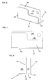
- FIGS. 6-8 illustrate the splice holder/cable management structure 40 of the WDM module 10 in detail.
- the splice holder/cable management structure 40 is configured to be placed within the module 10 between the top wall 52 and the multiplexer chip 20 (see FIGS. 1 and 23-27 ).
- the splice holder 40 includes a first wall 144 and second and third integral sidewalls 146, 148 extending perpendicularly from the first wall 144.
- the second and third sidewalls 146, 148 define a channel 150 thereinbetween for guiding fiber optic cables therethrough.
- the third wall 148 rests against the multiplexer chip 20 (see FIGS. 23-27 ).
- the second wall 146 and the top wall 52 of the main housing portion 14 of the module 10 define a pocket 152 for placing the fiber optic splice elements 42 therein.
- the second wall 146 keeps the fiber optic splice elements 42 in the pocket 152 separated from the fiber optic cables passing through the channel 150 defined between the second and third sidewalls 146, 148. In this manner, any epoxy residue remaining in the splice area is kept away from the cables passing through the channel 150.
- the cable may pass through the pocket 152, over the splice elements 42.
- the module input 84 for the multiplexer chip 20 may pass through the pocket 152, over the splice elements 42, when being routed to the input location 158 of the multiplexer chip (see FIG. 25 ).
- the third wall 148 of the splice holder/cable management structure 40 may include an inset portion defined by a notch 160 for accommodating fiber optic cables wrapped around a spool 162 defined by the first radius limiter 48.
- the notch 160 on the third wall 148 allows for expansion of fiber optic cables around the spool 162.
- FIGS. 9-11 illustrate the cable management structure 44 of the WDM module 10.
- the cable management structure 44 is configured to be placed into the module 10 after the placement of the multiplexer chip 20.
- the cable management structure 44 is configured to be located between the fiber optic splitter 18 and the add/drop filters 22.
- the cable management structure 44 may be located between the fiber optic splitter 18 and the bottom wall 54 of the module housing 14.
- the cable management structure 44 includes a U-shaped configuration with a first wall 164 and integral second and third sidewalls 166, 168 defining a channel 170 thereinbetween.
- the channel 170 guides fiber optic cables therethrough when routed within the module 10 as will be discussed in further detail below.
- the multiplexer chip 20 is placed into the main housing 14 first.
- the fiber optic splitter 18 and the add/drop filters 22 are placed after the multiplexer chip 20 with the splitter 18 being separated from the add/drop filters 22 by the cable management structure 44.
- the cable management structure 44 may be located between the splitter 18 and the bottom wall 54 of the main housing 14.
- Splice elements 42 are located adjacent the top wall 52 of the main housing 14 and are separated from the multiplexer chip 20 by the splice holder/cable management structure 40.
- the fiber retainer 46 is placed on the first radius limiter 48 after the fiber cables have been routed to keep the fiber cables wrapped around the spool 162 of the first radius limiter 48.
- the cover 16 holds the internal components of the module 10 within the housing 12.
- the WDM module 10 is shown in FIGS. 23-27 with the cover 16 and the fiber retainer 46 removed from the main housing portion 14 to illustrate the internal components and the routing of the cables therein. It should be noted that the routing of the cables illustrated in FIGS. 23-27 represents simply one example arrangement for the depicted module 10 and other arrangements are certainly possible.
- FIG. 23 an example routing arrangement of a first fiber optic cable 172 from an input location 82 of the WDM module 10 to an input location 154 of the fiber optic splitter 18 within the WDM module 10 is illustrated.
- a first cable 172 extends from the input connection location 82 of the module 10 upwardly toward the splice holder/cable management structure 40 and through the pocket 152 defined at the splice location, over the splice elements 42 (not shown in FIG. 23 ). From the splice holder/cable management structure 40, the first cable 172 extends downwardly and around the first radius limiter 48 and is spooled around the first radius limiter 48 as many times as necessary.
- the first cable 172 After leaving the first radius limiter 48, the first cable 172 extends toward the front of the module 10 upwardly and around the second radius limiter 110. From the second radius limiter 110, the first cable 172 extends downwardly and to the input location 154 of the fiber optic splitter 18.
- the fiber optic splitter 18 splits the optical signal into a plurality of signals. In the given embodiment, a 1x8 splitter is used, and, thus the signal from the first cable 172 may be split into eight signals.
- the fiber optic splitters may split an input signal into a plurality of the same signals.
- fiber optic splitters that split the input signal into different power levels (i.e., different ratios), rather than into the same signal, may be used.
- FIG. 24 an example routing of a fiber optic cable 174 from an output location 24 of the fiber optic splitter 18 to an input location 26 of an add/drop filter 22 that is configured to combine a split signal and a demultiplexed wavelength into a single output signal is illustrated. It should be noted that only one of the eight fiber cables 174 from the splitter 18 to the add/drop filter 22 is illustrated for clarity purposes. Other seven of the split signals carried by seven other fiber cables 174 would follow a similar path to the one that will be described.
- the second cable 174 extends from the output location 24 of the splitter 18 and upwardly around the first radius limiter 48.
- the second cable 174 is spooled around the first radius limiter 48 as many times as needed.
- the second cable 174 starts to extend toward the splice holder/cable management structure 40 and is spliced at the splice location to a third cable 176.
- the third cable 176 extends toward the front of the module 10 from the splice location and around the second radius limiter 110.
- the third cable 176 extends downwardly and through the channel 170 formed by the cable management structure 44 located between the splitter 18 and the add/drop filters 22 and toward the rear of the module 10.
- the third cable 176 goes upwardly around the first radius limiter 48 as many times as needed and through the channel 150 defined by the splice holder/cable management structure 40 toward the front of the module 10. From the splice holder/cable management structure 40, the third cable 176 goes around the second radius limiter 110 once again and downwardly to the input location 26 of the add/drop filter 22 (i.e., the PASS leg of the filter 22).
- FIG. 25 an example routing of a fiber optic cable 178 from an input location 84 of the WDM module 10 to an input location 158 of the multiplexer chip 20 within the WDM module 10 is illustrated.
- the fourth cable 178 extends from the input connection 84 of the module 10 upwardly toward the splice holder/cable management structure 40 and through the pocket 152 defined at the splice location, over the splice elements 42 (not shown in FIG. 25 ). From there, the fourth cable 178 extends downwardly and around the first radius limiter 48 and is spooled around the first radius limiter 48 as many times as needed. After leaving the first radius limiter 48, the fourth cable 178 ends up at the input location 158 of the multiplexer chip 20.
- the multiplexer chip 20 demultiplexes the optical signal carried by the fourth cable 178 into different wavelengths of laserlight. In the given embodiment, an 8-channel multiplexer chip is used, and, thus, the signal from the fourth cable 178 will be demultiplexed into eight different wavelengths.
- FIG. 26 an example routing of a fiber optic cable 180 from an output location 182 of the multiplexer chip 20 to an input location 28 of an add/drop filter 22 that is configured to combine a split signal and a demultiplexed wavelength into a single output signal is illustrated. It should be noted that routing of only one of the eight fiber cables 180 from the multiplexer chip 20 to the add/drop filter 22 is illustrated for clarity purposes. Other seven of the cables 180 carrying the other seven demultiplexed wavelengths would follow a similar path to the one that will be described.
- the fifth cable 180 extends from the output location 182 of the multiplexer chip 20 and upwardly and around the second radius limiter 110. From the second radius limiter 110, the fifth cable 180 extends toward the rear of the module 10 through the channel 150 defined by the splice holder/cable management structure 40. From the splice holder/cable management structure 40, the fifth cable 180 extends downwardly around the first radius limiter 48 as many times as needed. From the first radius limiter 48, the fifth cable 180 extends toward the front of the module 10 through the channel 170 formed by the cable management structure 44. From the cable management structure 44, the fifth cable 180 extends upwardly toward the second radius limiter 110 and around the second radius limiter 110.
- the fifth cable 180 extends toward the splice holder/cable management structure 40 and is spliced at the splice location to a sixth cable 184.
- the sixth cable 184 extends from the splice location toward the rear of the module 10 and around the first radius limiter 48.
- the sixth cable 184 is spooled around the first radius limiter 48 as many times as needed. From the first radius limiter 48, the sixth cable 184 extends toward the front of the module 10 to the input location 28 of the add/drop filter 22 (i.e., REF leg of the filter 22).
- FIG. 27 an example routing of a fiber optic cable 186 from an output location 116 of the add/drop filter 22 (i.e., COM leg of filter 22) that is configured to combine a split signal and a demultiplexed wavelength to an output signal of the WDM module 10 is illustrated.
- the add/drop filter 22 i.e., COM leg of filter 22
- the seventh cable 186 carrying a combination signal extends from the output 116 of the add/drop filter 22 toward the rear of the module 10.
- the seventh cable 186 extends upwardly around the first radius limiter 48 and is spooled around the first radius limiter 48 as many time as needed. From the first radius limiter 48, the seventh cable 186 extends toward the front of the module 10 through the channel 150 defined by the splice holder/cable management structure 40. From the splice holder/cable management structure 40, the seventh cable 186 is led to the crimp holders 112 of the module 10 and is crimped to a crimp element 114.
- the eighth cable 34 extends from the other end of the crimp element 114 to the cable exit 38 of the module 10. It should be noted that the routing for only one of the cables going from the add/drop filter output 116 to the module output has been described for clarity purposes. There are eight add/drop filters 22 for combining a split signal and a demultiplexed wavelength. Each of the cables extending from each add/drop filter output 116 to the module exit 38 may follow a similar path to that described above.
- routing of the fiber optic cables within module 10 as shown in FIGS 23-27 is only one example and other ways of routing the cables within the module 10 are possible.
- the WDM module 10 may house an 8-channel wavelength division multiplexing chip. According to another embodiment, the WDM module 10 may house a 4-channel wavelength division multiplexing chip. According to another embodiment, the WDM module 10 may house a 16-channel wavelength division multiplexing chip. In other embodiments, the module 10 may house other types of wavelength division multiplexing chips. In all the embodiments, the WDM module 10 may house fiber optic splitters that are configured to split a signal into a number of signals corresponding to the number of demultiplexed wavelengths. The fiber optic splitters used may power split the signal into the same signals or into different power levels/ratios.
Landscapes
- Physics & Mathematics (AREA)
- General Physics & Mathematics (AREA)
- Optics & Photonics (AREA)
- Engineering & Computer Science (AREA)
- Computer Networks & Wireless Communication (AREA)
- Signal Processing (AREA)
- Light Guides In General And Applications Therefor (AREA)
- Microelectronics & Electronic Packaging (AREA)
- Optical Communication System (AREA)
Claims (7)
- Telekommunikationsmodul (10), umfassend:ein Gehäuse (12), das einen Innenraum definiert und eine erste Seitenwand (50), eine zweite Seitenwand (60), eine obere Wand (52), eine untere Wand (54), eine hintere Wand (56) und eine vordere Wand (58) umfasst, wobei das Gehäuse (12) sich in einer Längsrichtung von der vorderen Wand (58) zur hinteren Wand (56) erstreckt;einen ersten Moduleingabeort (84), der sich neben der vorderen Wand (58) des Gehäuses (12) befindet, und einen zweiten Moduleingabeort (82), der sich neben der vorderen Wand (58) des Gehäuses (12) befindet;einen Modulausgabeort (38), der sich neben der vorderen Wand (58) des Gehäuses (12) befindet;dadurch gekennzeichnet, dass:ein Wellenlängen-Multiplexer/Demultiplexer für optische Wellenlängen (20) im Innern des Gehäuses (12) installiert ist und eine Multiplexerlänge hat, die sich im Allgemeinen parallel zur Längsrichtung des Gehäuses (12) erstreckt, wobei der Wellenlängen-Multiplexer/Demultiplexer für optische Wellenlängen (20) einen Multiplexereingabeort (158) enthält, der zur hinteren Wand (56) weist, und einen Multiplexerausgabeort (182) umfasst, der zur vorderen Wand (58) weist, wobei der Wellenlängen-Multiplexer/Demultiplexer für optische Wellenlängen (20) dafür konfiguriert ist, eine optische Signaleingabe in das Telekommunikationsmodul (10) über den ersten Moduleingabeort (84) in mehrere verschiedene Wellenlängen zu entmultiplexen;ein faseroptischer Teiler (18) im Innern des Gehäuses (12) installiert ist und eine Teilerlänge hat, die sich im Allgemeinen parallel zur Längsrichtung des Gehäuses (12) erstreckt, wobei der faseroptische Teiler (18) einen Teilereingabeort (154) umfasst, der zur vorderen Wand (58) weist, und einen Teilerausgabeort (24), der zur hinteren Wand (56) weist, wobei der faseroptische Teiler (18) so konfiguriert ist, dass er eine optische Signaleingabe in das Telekommunikationsmodul (10) über den zweiten Moduleingabeort (82) in mehrere Signale aufspaltet; undmehrere optische Add/Dropfilter (22) im Innern des Gehäuses (12) installiert sind, wobei jedes der optischen Add/Dropfilter (22) eine Filterlänge hat, die sich im Allgemeinen parallel zur Längsrichtung des Gehäuses (12) erstreckt, wobei jedes der optischen Add/Dropfilter (22) so konfiguriert ist, dass es eines der Signale, das vom faseroptischen Teiler (18) geteilt wurde, und eine der Wellenlängen, die vom Wellenlängen-Multiplexer/Demultiplexer für optische Wellenlängen (20) entmultiplext wurde, in ein kombiniertes Ausgangssignal kombiniert, das vom Telekommunikationsmodul über den Modulausgabeort (38) ausgegeben wird, wobei jedes optische Add/Dropfilter (22) einen ersten Filtereingabeort (26), der zur vorderen Wand (58) weist, einen zweiten Filtereingabeort (28), der zur hinteren Wand weist, und einen Filterausgabeort (116) umfasst, der zur hinteren Wand (56) weist, wobei der erste Filtereingabeort (26) so konfiguriert ist, dass er ein Signal vom faseroptischen Teiler (18) empfängt, und der zweite Filtereingabeort (28) so konfiguriert ist, dass er ein Signal vom Wellenlängen-Multiplexer/Demultiplexer für optische Wellenlängen (20) empfängt.
- Telekommunikationsmodul nach Anspruch 1, das ferner eine erste Kabelmanagementstruktur (48) umfasst, die sich neben der hinteren Wand (56) zum Führen von Kabeln befindet, welche sich im Innern des Gehäuses (12) erstrecken, wobei die erste Kabelmanagementstruktur (48) eine Spule umfasst, die an einer gekrümmten Wand anliegt.
- Telekommunikationsmodul nach Anspruch 2, das ferner eine zweite Kabelmanagementstruktur (110) umfasst, die sich neben der vorderen Wand (58) zum Führen von Kabeln befindet, welche sich im Innern des Gehäuses (12) erstrecken, wobei die zweite Kabelmanagementstruktur (110) eine gekrümmte Wand umfasst.
- Telekommunikationsmodul nach Anspruch 1, wobei der faseroptische Teiler (18) ein 1x8-Teiler ist, der Wellenlängen-Multiplexer/Demultiplexer für optische Wellenlängen (20) ein 8-Kanal-Multiplexer/Demultiplexer ist und die mehreren optischen Add/Dropfilter (22) acht optische Add/Dropfilter umfassen.
- Telekommunikationsmodul nach Anspruch 1, das ferner einen oberen Flansch (70), einen unteren Flansch (72) und eine flexible Verriegelung (100) neben der vorderen Wand (58) zur verschiebbaren Einführung in ein Telekommunikationschassis umfasst.
- Telekommunikationsmodul nach Anspruch 1, das ferner Kabelspleißelemente (42) umfasst, die Längen haben, welche sich im Allgemeinen parallel zur Längsrichtung des Gehäuses (12) erstrecken, wobei die Spleißelemente (42) zum Spleißen von Kabeln dienen, die sich zwischen dem Wellenlängen-Multiplexer/Demultiplexer für optische Wellenlängen (20) und den optischen Add/Dropfiltern (22) erstrecken, und von Kabeln, die sich zwischen dem faseroptischen Teiler (18) und den optischen Add/Dropfiltern (22) erstrecken.
- Telekommunikationsmodul nach Anspruch 1, wobei die Wellenlängen-Multiplexer/Demultiplexer für optische Wellenlängen (20), der faseroptische Teiler (18) und die optischen Add/Dropfilter (22) lösbar innerhalb des Gehäuses (12) installiert sind, wobei das Telekommunikationsmodul (10) ferner eine abnehmbare Abdeckung (16) umfasst, um Zugang zu dem Wellenlängen-Multiplexer/Demultiplexer für optische Wellenlängen (20), dem faseroptischen Teiler (18) und den optischen Add/Dropfiltern (22) zu erhalten.
Applications Claiming Priority (3)
| Application Number | Priority Date | Filing Date | Title |
|---|---|---|---|
| US2445008P | 2008-01-29 | 2008-01-29 | |
| US12/360,719 US8107816B2 (en) | 2008-01-29 | 2009-01-27 | Wavelength division multiplexing module |
| PCT/US2009/032349 WO2009097388A1 (en) | 2008-01-29 | 2009-01-29 | Wavelength multiplexing module |
Publications (2)
| Publication Number | Publication Date |
|---|---|
| EP2243237A1 EP2243237A1 (de) | 2010-10-27 |
| EP2243237B1 true EP2243237B1 (de) | 2013-09-18 |
Family
ID=40467350
Family Applications (1)
| Application Number | Title | Priority Date | Filing Date |
|---|---|---|---|
| EP09706377.0A Not-in-force EP2243237B1 (de) | 2008-01-29 | 2009-01-29 | Wellenlängen multiplexendes modul |
Country Status (8)
| Country | Link |
|---|---|
| US (6) | US8107816B2 (de) |
| EP (1) | EP2243237B1 (de) |
| CN (1) | CN101933266B (de) |
| AU (1) | AU2009209134B2 (de) |
| CA (1) | CA2711459C (de) |
| ES (1) | ES2434866T3 (de) |
| MX (1) | MX2010008032A (de) |
| WO (1) | WO2009097388A1 (de) |
Families Citing this family (21)
| Publication number | Priority date | Publication date | Assignee | Title |
|---|---|---|---|---|
| US8559818B2 (en) * | 2007-10-26 | 2013-10-15 | Adc Telecommunications, Inc. | Methods and systems for delivery of multiple passive optical network services |
| US8107816B2 (en) | 2008-01-29 | 2012-01-31 | Adc Telecommunications, Inc. | Wavelength division multiplexing module |
| US8837940B2 (en) * | 2010-04-14 | 2014-09-16 | Adc Telecommunications, Inc. | Methods and systems for distributing fiber optic telecommunication services to local areas and for supporting distributed antenna systems |
| US10031305B2 (en) | 2012-12-19 | 2018-07-24 | CommScope Connectivity Belgium BVBA | Distribution device with incrementally added splitters |
| US20150033294A1 (en) * | 2013-07-26 | 2015-01-29 | Xtera Communications, Inc. | Network management system architecture of a telecommunications network |
| MX362068B (es) * | 2013-08-26 | 2019-01-07 | Adc Telecommunications Inc | Arreglo de multiplexor de división de onda para redes de celda pequeña. |
| CN106687841B (zh) | 2014-06-17 | 2020-08-14 | 康普连通比利时私人有限公司 | 线缆配线系统 |
| US9442266B2 (en) * | 2014-09-11 | 2016-09-13 | Commscope Technologies Llc | Fiber optic enclosure for retrofitting pedestals in the field |
| EP3262774B1 (de) * | 2015-02-26 | 2022-08-31 | Commscope Technologies LLC | Verteilte antennenarchitektur |
| EP3338125A4 (de) | 2015-08-21 | 2019-04-17 | Commscope Technologies LLC | Telekommunikationsmodul |
| US10606009B2 (en) | 2015-12-01 | 2020-03-31 | CommScope Connectivity Belgium BVBA | Cable distribution system with fan out devices |
| WO2017092046A1 (zh) * | 2015-12-04 | 2017-06-08 | 华为技术有限公司 | 一种光器件和光传输系统 |
| WO2017129815A1 (en) | 2016-01-28 | 2017-08-03 | CommScope Connectivity Belgium BVBA | Modular hybrid closure |
| US10222571B2 (en) | 2016-04-07 | 2019-03-05 | Commscope Technologies Llc | Telecommunications module and frame |
| US10317639B2 (en) | 2016-11-11 | 2019-06-11 | CommScope Connectivity Belgium BVBA | Fiber optic network architecture |
| US10677485B2 (en) | 2017-09-19 | 2020-06-09 | Honeywell International Inc. | Determining the cause of a fault in an HVAC system |
| US10715271B1 (en) * | 2019-09-30 | 2020-07-14 | Corning Research & Development Corporation | Dense wavelength division multiplexing fiber optic apparatuses and related equipment |
| US11166392B2 (en) * | 2019-10-21 | 2021-11-02 | Ciena Corporation | Spring-type latch for securing a networking module within a slot of a chassis |
| US11824252B2 (en) * | 2021-02-08 | 2023-11-21 | Commscope Technologies Llc | Small cell antenna strand mounts and assemblies |
| US12442984B2 (en) * | 2021-10-04 | 2025-10-14 | Corning Research & Development Corporation | Integrated connector-wavelength division multiplexing device and fiber optic module including such devices |
| EP4695639A1 (de) * | 2023-04-12 | 2026-02-18 | Viaphoton, Inc. | Vorterminiertes querverbindungssystem |
Family Cites Families (72)
| Publication number | Priority date | Publication date | Assignee | Title |
|---|---|---|---|---|
| US1657953A (en) * | 1926-07-10 | 1928-01-31 | Edwin P Brandt | Snubber |
| US4435612A (en) * | 1982-03-09 | 1984-03-06 | Communication Technology Corporation | Cable splice housing |
| FR2581767B1 (fr) | 1985-05-10 | 1988-08-26 | Pouyet Sa Henri | Point de branchement pour cables a fibres optiques |
| US5189410A (en) * | 1989-12-28 | 1993-02-23 | Fujitsu Limited | Digital cross connect system |
| US5363465A (en) * | 1993-02-19 | 1994-11-08 | Adc Telecommunications, Inc. | Fiber optic connector module |
| US5432875A (en) * | 1993-02-19 | 1995-07-11 | Adc Telecommunications, Inc. | Fiber optic monitor module |
| US5317663A (en) * | 1993-05-20 | 1994-05-31 | Adc Telecommunications, Inc. | One-piece SC adapter |
| US5339379A (en) * | 1993-06-18 | 1994-08-16 | Telect, Inc. | Telecommunication fiber optic cable distribution apparatus |
| TW232757B (en) * | 1994-01-21 | 1994-10-21 | Adc Telecommunications Inc | High-density fiber distribution frame |
| US5600746A (en) | 1995-02-28 | 1997-02-04 | Lucent Technologies Inc. | Patch panel and collar for optical fiber couplers |
| US5627925A (en) * | 1995-04-07 | 1997-05-06 | Lucent Technologies Inc. | Non-blocking optical cross-connect structure for telecommunications network |
| GB2300978A (en) | 1995-04-19 | 1996-11-20 | Smiths Industries Plc | Shutter for connector |
| US5613030A (en) | 1995-05-15 | 1997-03-18 | The Whitaker Corporation | High density fiber optic interconnection enclosure |
| US5701380A (en) * | 1996-06-24 | 1997-12-23 | Telect, Inc. | Fiber optic module for high density supply of patching and splicing |
| US5694511A (en) * | 1996-09-09 | 1997-12-02 | Lucent Technologies Inc. | Optical switching apparatus and method for use in the construction mode testing of a modular fiber administration system |
| US5793909A (en) | 1996-09-09 | 1998-08-11 | Lucent Technologies Inc. | Optical monitoring and test access module |
| KR100369725B1 (ko) * | 1996-12-06 | 2003-01-30 | 텔코디아 테크놀로지스, 인코포레이티드 | 존속가능한 다중파장 광학 통신 네트워크를 위한 인터-링 교차접속장치 |
| US5946440A (en) * | 1997-11-17 | 1999-08-31 | Adc Telecommunications, Inc. | Optical fiber cable management device |
| US6208796B1 (en) * | 1998-07-21 | 2001-03-27 | Adc Telecommunications, Inc. | Fiber optic module |
| WO2000041430A1 (en) | 1998-12-30 | 2000-07-13 | Optical Technologies U.S.A. Corp. | Wavelength-modular optical cross-connect switch |
| US6760531B1 (en) * | 1999-03-01 | 2004-07-06 | Adc Telecommunications, Inc. | Optical fiber distribution frame with outside plant enclosure |
| US6556763B1 (en) * | 1999-03-01 | 2003-04-29 | Adc Telecommunications, Inc. | Optical fiber distribution frame with connector modules |
| US6424781B1 (en) * | 1999-03-01 | 2002-07-23 | Adc Telecommunications, Inc. | Optical fiber distribution frame with pivoting connector panels |
| US6535682B1 (en) * | 1999-03-01 | 2003-03-18 | Adc Telecommunications, Inc. | Optical fiber distribution frame with connector modules |
| US6370294B1 (en) * | 1999-06-25 | 2002-04-09 | Adc Telecommunications, Inc. | Fiber optic circuit and module with switch |
| SE9903521L (sv) | 1999-09-27 | 2001-03-28 | Queyton Systems Ab | Anslutning av en ADD/DROP-NOD |
| US6263136B1 (en) * | 1999-10-29 | 2001-07-17 | Lucent Technologies | Intelligent optical transmitter module |
| DE19956067A1 (de) * | 1999-11-22 | 2001-05-23 | Rxs Kabelgarnituren Gmbh & Co | Kassette zur Aufnahme von Lichtwellenleitern mit Überlängen und Lichtwellenleiter-Spleißverbindungen |
| US6363183B1 (en) * | 2000-01-04 | 2002-03-26 | Seungug Koh | Reconfigurable and scalable intergrated optic waveguide add/drop multiplexing element using micro-opto-electro-mechanical systems and methods of fabricating thereof |
| US6418262B1 (en) * | 2000-03-13 | 2002-07-09 | Adc Telecommunications, Inc. | Fiber distribution frame with fiber termination blocks |
| US6647197B1 (en) * | 2000-06-02 | 2003-11-11 | Panduit Corp. | Modular latch and guide rail arrangement for use in fiber optic cable management systems |
| US6668108B1 (en) * | 2000-06-02 | 2003-12-23 | Calient Networks, Inc. | Optical cross-connect switch with integrated optical signal tap |
| AU2002236428A1 (en) | 2000-07-31 | 2002-05-21 | Litton Systems Inc. | Multi-level optical fiber and component storage tray |
| US6523916B2 (en) * | 2000-12-22 | 2003-02-25 | Aurora Networks, Inc. | Chassis with repositionable plates |
| US6532332B2 (en) * | 2001-02-15 | 2003-03-11 | Adc Telecommunications, Inc. | Cable guide for fiber termination block |
| WO2002075403A1 (en) * | 2001-03-16 | 2002-09-26 | Photuris, Inc. | Method and apparatus for providing gain equalizing to an optical signal in an optical communication system |
| US6533616B2 (en) * | 2001-04-13 | 2003-03-18 | Adc Telecommunications, Inc. | DSX jack including sliding rear connector |
| US6824312B2 (en) * | 2001-06-04 | 2004-11-30 | Adc Telecommunications, Inc. | Telecommunications chassis and module |
| US6591051B2 (en) * | 2001-11-16 | 2003-07-08 | Adc Telecommunications, Inc. | Fiber termination block with angled slide |
| DE20201170U1 (de) | 2002-01-15 | 2002-05-29 | Infineon Technologies AG, 81669 München | Vorrichtung zum Schutz der Steckeraufnahme eines opto-elektronischen Bauelements |
| US6688780B2 (en) * | 2002-02-07 | 2004-02-10 | Amphenol Corporation | Cantilevered shutter for optical adapter |
| US6850685B2 (en) * | 2002-03-27 | 2005-02-01 | Adc Telecommunications, Inc. | Termination panel with pivoting bulkhead and cable management |
| US6937807B2 (en) * | 2002-04-24 | 2005-08-30 | Adc Telecommunications, Inc. | Cable management panel with sliding drawer |
| DE10219892A1 (de) | 2002-05-03 | 2004-02-05 | Krone Gmbh | Kupplung für Glasfaserverbinder |
| JP4266319B2 (ja) * | 2002-09-06 | 2009-05-20 | 株式会社精工技研 | 光コネクタプラグ及び光コネクタ |
| US6822874B1 (en) * | 2002-11-12 | 2004-11-23 | Wooshcom Corporation | Modular high availability electronic product architecture with flexible I/O |
| WO2004052066A1 (ja) * | 2002-11-29 | 2004-06-17 | Fujitsu Limited | 電子装置に搭載されるユニット及び当該電子装置の伝送線路の接続機構 |
| US7142764B2 (en) * | 2003-03-20 | 2006-11-28 | Tyco Electronics Corporation | Optical fiber interconnect cabinets, termination modules and fiber connectivity management for the same |
| US7035519B2 (en) | 2003-05-02 | 2006-04-25 | Panduit Corp. | Fiber optic connector removal tool |
| US6832035B1 (en) * | 2003-05-30 | 2004-12-14 | Lucent Technologies Inc. | Optical fiber connection system |
| US6885798B2 (en) * | 2003-09-08 | 2005-04-26 | Adc Telecommunications, Inc. | Fiber optic cable and furcation module |
| US7303220B2 (en) * | 2003-09-29 | 2007-12-04 | Richco Inc. | Connector coupling/decoupling tool |
| US7141738B2 (en) * | 2004-02-02 | 2006-11-28 | 3M Innovative Properties Company | Re-enterable splice enclosure |
| US20050232565A1 (en) * | 2004-04-16 | 2005-10-20 | Ross Heggestad | Normal through optical panel |
| US20050232551A1 (en) * | 2004-04-16 | 2005-10-20 | Cheng-Pei Chang | Devices for preventing lens contamination in optoelectronic modules and connectors |
| EP1589361A1 (de) | 2004-04-23 | 2005-10-26 | Agilent Technologies, Inc. | Gehäuse für das optische Element |
| US7376322B2 (en) * | 2004-11-03 | 2008-05-20 | Adc Telecommunications, Inc. | Fiber optic module and system including rear connectors |
| JP4382635B2 (ja) | 2004-11-10 | 2009-12-16 | 富士通株式会社 | 光伝送装置 |
| JP4528147B2 (ja) * | 2005-02-01 | 2010-08-18 | 株式会社日立製作所 | 光波長挿入分岐装置およびそれを用いた光ネットワーク装置 |
| US7194181B2 (en) * | 2005-03-31 | 2007-03-20 | Adc Telecommunications, Inc. | Adapter block including connector storage |
| US7400813B2 (en) * | 2005-05-25 | 2008-07-15 | Adc Telecommunications, Inc. | Fiber optic splitter module |
| US7376323B2 (en) * | 2005-05-25 | 2008-05-20 | Adc Telecommunications, Inc. | Fiber optic adapter module |
| US8190027B2 (en) * | 2006-07-12 | 2012-05-29 | Tellabs Operations, Inc. | Multifunctional and reconfigurable optical node and optical network |
| US20070036503A1 (en) * | 2005-08-10 | 2007-02-15 | Solheid James J | Fiber optic adapter modules with identification system |
| US7346254B2 (en) * | 2005-08-29 | 2008-03-18 | Adc Telecommunications, Inc. | Fiber optic splitter module with connector access |
| US7190874B1 (en) * | 2005-10-03 | 2007-03-13 | Adc Telecommunications, Inc. | Fiber demarcation box with cable management |
| US7245809B1 (en) * | 2005-12-28 | 2007-07-17 | Adc Telecommunications, Inc. | Splitter modules for fiber distribution hubs |
| US7418181B2 (en) * | 2006-02-13 | 2008-08-26 | Adc Telecommunications, Inc. | Fiber optic splitter module |
| US7454113B2 (en) * | 2006-07-20 | 2008-11-18 | Adc Telecommunications, Inc. | Grounding device for fiber storage trays |
| US7536075B2 (en) | 2007-10-22 | 2009-05-19 | Adc Telecommunications, Inc. | Wavelength division multiplexing module |
| US8559818B2 (en) | 2007-10-26 | 2013-10-15 | Adc Telecommunications, Inc. | Methods and systems for delivery of multiple passive optical network services |
| US8107816B2 (en) | 2008-01-29 | 2012-01-31 | Adc Telecommunications, Inc. | Wavelength division multiplexing module |
-
2009
- 2009-01-27 US US12/360,719 patent/US8107816B2/en not_active Expired - Fee Related
- 2009-01-29 MX MX2010008032A patent/MX2010008032A/es active IP Right Grant
- 2009-01-29 CA CA2711459A patent/CA2711459C/en active Active
- 2009-01-29 EP EP09706377.0A patent/EP2243237B1/de not_active Not-in-force
- 2009-01-29 ES ES09706377T patent/ES2434866T3/es active Active
- 2009-01-29 WO PCT/US2009/032349 patent/WO2009097388A1/en not_active Ceased
- 2009-01-29 CN CN200980103530.6A patent/CN101933266B/zh not_active Expired - Fee Related
- 2009-01-29 AU AU2009209134A patent/AU2009209134B2/en not_active Ceased
-
2012
- 2012-01-31 US US13/362,210 patent/US8660429B2/en active Active
-
2014
- 2014-01-17 US US14/157,644 patent/US9197346B2/en not_active Expired - Fee Related
-
2015
- 2015-11-02 US US14/930,332 patent/US9768900B2/en active Active
-
2017
- 2017-09-18 US US15/706,969 patent/US10439750B2/en active Active
-
2019
- 2019-09-30 US US16/588,033 patent/US11658763B2/en active Active
Also Published As
| Publication number | Publication date |
|---|---|
| EP2243237A1 (de) | 2010-10-27 |
| US20120128311A1 (en) | 2012-05-24 |
| CA2711459A1 (en) | 2009-08-06 |
| CN101933266A (zh) | 2010-12-29 |
| ES2434866T3 (es) | 2013-12-17 |
| AU2009209134A1 (en) | 2009-08-06 |
| WO2009097388A1 (en) | 2009-08-06 |
| US8107816B2 (en) | 2012-01-31 |
| AU2009209134B2 (en) | 2013-11-14 |
| CN101933266B (zh) | 2014-10-22 |
| US9768900B2 (en) | 2017-09-19 |
| US20150234141A1 (en) | 2015-08-20 |
| MX2010008032A (es) | 2010-08-23 |
| US8660429B2 (en) | 2014-02-25 |
| CA2711459C (en) | 2016-08-23 |
| US9197346B2 (en) | 2015-11-24 |
| US11658763B2 (en) | 2023-05-23 |
| US20180123722A1 (en) | 2018-05-03 |
| US10439750B2 (en) | 2019-10-08 |
| US20160173222A1 (en) | 2016-06-16 |
| US20090196616A1 (en) | 2009-08-06 |
| US20200145121A1 (en) | 2020-05-07 |
Similar Documents
| Publication | Publication Date | Title |
|---|---|---|
| US11658763B2 (en) | Wavelength division multiplexing module | |
| US10436996B2 (en) | Wavelength division multiplexing module | |
| US12055782B2 (en) | Telecommunications module |
Legal Events
| Date | Code | Title | Description |
|---|---|---|---|
| PUAI | Public reference made under article 153(3) epc to a published international application that has entered the european phase |
Free format text: ORIGINAL CODE: 0009012 |
|
| 17P | Request for examination filed |
Effective date: 20100806 |
|
| AK | Designated contracting states |
Kind code of ref document: A1 Designated state(s): AT BE BG CH CY CZ DE DK EE ES FI FR GB GR HR HU IE IS IT LI LT LU LV MC MK MT NL NO PL PT RO SE SI SK TR |
|
| AX | Request for extension of the european patent |
Extension state: AL BA RS |
|
| 17Q | First examination report despatched |
Effective date: 20101213 |
|
| DAX | Request for extension of the european patent (deleted) | ||
| GRAP | Despatch of communication of intention to grant a patent |
Free format text: ORIGINAL CODE: EPIDOSNIGR1 |
|
| INTG | Intention to grant announced |
Effective date: 20130326 |
|
| GRAS | Grant fee paid |
Free format text: ORIGINAL CODE: EPIDOSNIGR3 |
|
| GRAA | (expected) grant |
Free format text: ORIGINAL CODE: 0009210 |
|
| AK | Designated contracting states |
Kind code of ref document: B1 Designated state(s): AT BE BG CH CY CZ DE DK EE ES FI FR GB GR HR HU IE IS IT LI LT LU LV MC MK MT NL NO PL PT RO SE SI SK TR |
|
| REG | Reference to a national code |
Ref country code: GB Ref legal event code: FG4D |
|
| REG | Reference to a national code |
Ref country code: CH Ref legal event code: EP |
|
| REG | Reference to a national code |
Ref country code: IE Ref legal event code: FG4D |
|
| REG | Reference to a national code |
Ref country code: AT Ref legal event code: REF Ref document number: 633254 Country of ref document: AT Kind code of ref document: T Effective date: 20131015 |
|
| REG | Reference to a national code |
Ref country code: DE Ref legal event code: R096 Ref document number: 602009018874 Country of ref document: DE Effective date: 20131114 |
|
| REG | Reference to a national code |
Ref country code: ES Ref legal event code: FG2A Ref document number: 2434866 Country of ref document: ES Kind code of ref document: T3 Effective date: 20131217 |
|
| PG25 | Lapsed in a contracting state [announced via postgrant information from national office to epo] |
Ref country code: NO Free format text: LAPSE BECAUSE OF FAILURE TO SUBMIT A TRANSLATION OF THE DESCRIPTION OR TO PAY THE FEE WITHIN THE PRESCRIBED TIME-LIMIT Effective date: 20131218 Ref country code: SE Free format text: LAPSE BECAUSE OF FAILURE TO SUBMIT A TRANSLATION OF THE DESCRIPTION OR TO PAY THE FEE WITHIN THE PRESCRIBED TIME-LIMIT Effective date: 20130918 Ref country code: LT Free format text: LAPSE BECAUSE OF FAILURE TO SUBMIT A TRANSLATION OF THE DESCRIPTION OR TO PAY THE FEE WITHIN THE PRESCRIBED TIME-LIMIT Effective date: 20130918 Ref country code: CY Free format text: LAPSE BECAUSE OF FAILURE TO SUBMIT A TRANSLATION OF THE DESCRIPTION OR TO PAY THE FEE WITHIN THE PRESCRIBED TIME-LIMIT Effective date: 20130710 Ref country code: HR Free format text: LAPSE BECAUSE OF FAILURE TO SUBMIT A TRANSLATION OF THE DESCRIPTION OR TO PAY THE FEE WITHIN THE PRESCRIBED TIME-LIMIT Effective date: 20130918 |
|
| REG | Reference to a national code |
Ref country code: NL Ref legal event code: VDEP Effective date: 20130918 |
|
| REG | Reference to a national code |
Ref country code: AT Ref legal event code: MK05 Ref document number: 633254 Country of ref document: AT Kind code of ref document: T Effective date: 20130918 |
|
| REG | Reference to a national code |
Ref country code: LT Ref legal event code: MG4D |
|
| PG25 | Lapsed in a contracting state [announced via postgrant information from national office to epo] |
Ref country code: GR Free format text: LAPSE BECAUSE OF FAILURE TO SUBMIT A TRANSLATION OF THE DESCRIPTION OR TO PAY THE FEE WITHIN THE PRESCRIBED TIME-LIMIT Effective date: 20131219 Ref country code: SI Free format text: LAPSE BECAUSE OF FAILURE TO SUBMIT A TRANSLATION OF THE DESCRIPTION OR TO PAY THE FEE WITHIN THE PRESCRIBED TIME-LIMIT Effective date: 20130918 Ref country code: LV Free format text: LAPSE BECAUSE OF FAILURE TO SUBMIT A TRANSLATION OF THE DESCRIPTION OR TO PAY THE FEE WITHIN THE PRESCRIBED TIME-LIMIT Effective date: 20130918 Ref country code: FI Free format text: LAPSE BECAUSE OF FAILURE TO SUBMIT A TRANSLATION OF THE DESCRIPTION OR TO PAY THE FEE WITHIN THE PRESCRIBED TIME-LIMIT Effective date: 20130918 |
|
| PG25 | Lapsed in a contracting state [announced via postgrant information from national office to epo] |
Ref country code: CY Free format text: LAPSE BECAUSE OF FAILURE TO SUBMIT A TRANSLATION OF THE DESCRIPTION OR TO PAY THE FEE WITHIN THE PRESCRIBED TIME-LIMIT Effective date: 20130918 Ref country code: BE Free format text: LAPSE BECAUSE OF FAILURE TO SUBMIT A TRANSLATION OF THE DESCRIPTION OR TO PAY THE FEE WITHIN THE PRESCRIBED TIME-LIMIT Effective date: 20130918 |
|
| PG25 | Lapsed in a contracting state [announced via postgrant information from national office to epo] |
Ref country code: SK Free format text: LAPSE BECAUSE OF FAILURE TO SUBMIT A TRANSLATION OF THE DESCRIPTION OR TO PAY THE FEE WITHIN THE PRESCRIBED TIME-LIMIT Effective date: 20130918 Ref country code: IS Free format text: LAPSE BECAUSE OF FAILURE TO SUBMIT A TRANSLATION OF THE DESCRIPTION OR TO PAY THE FEE WITHIN THE PRESCRIBED TIME-LIMIT Effective date: 20140118 Ref country code: CZ Free format text: LAPSE BECAUSE OF FAILURE TO SUBMIT A TRANSLATION OF THE DESCRIPTION OR TO PAY THE FEE WITHIN THE PRESCRIBED TIME-LIMIT Effective date: 20130918 Ref country code: NL Free format text: LAPSE BECAUSE OF FAILURE TO SUBMIT A TRANSLATION OF THE DESCRIPTION OR TO PAY THE FEE WITHIN THE PRESCRIBED TIME-LIMIT Effective date: 20130918 Ref country code: EE Free format text: LAPSE BECAUSE OF FAILURE TO SUBMIT A TRANSLATION OF THE DESCRIPTION OR TO PAY THE FEE WITHIN THE PRESCRIBED TIME-LIMIT Effective date: 20130918 |
|
| PG25 | Lapsed in a contracting state [announced via postgrant information from national office to epo] |
Ref country code: PL Free format text: LAPSE BECAUSE OF FAILURE TO SUBMIT A TRANSLATION OF THE DESCRIPTION OR TO PAY THE FEE WITHIN THE PRESCRIBED TIME-LIMIT Effective date: 20130918 Ref country code: AT Free format text: LAPSE BECAUSE OF FAILURE TO SUBMIT A TRANSLATION OF THE DESCRIPTION OR TO PAY THE FEE WITHIN THE PRESCRIBED TIME-LIMIT Effective date: 20130918 |
|
| REG | Reference to a national code |
Ref country code: DE Ref legal event code: R097 Ref document number: 602009018874 Country of ref document: DE |
|
| PG25 | Lapsed in a contracting state [announced via postgrant information from national office to epo] |
Ref country code: PT Free format text: LAPSE BECAUSE OF FAILURE TO SUBMIT A TRANSLATION OF THE DESCRIPTION OR TO PAY THE FEE WITHIN THE PRESCRIBED TIME-LIMIT Effective date: 20140120 |
|
| PLBE | No opposition filed within time limit |
Free format text: ORIGINAL CODE: 0009261 |
|
| STAA | Information on the status of an ep patent application or granted ep patent |
Free format text: STATUS: NO OPPOSITION FILED WITHIN TIME LIMIT |
|
| 26N | No opposition filed |
Effective date: 20140619 |
|
| PG25 | Lapsed in a contracting state [announced via postgrant information from national office to epo] |
Ref country code: LU Free format text: LAPSE BECAUSE OF FAILURE TO SUBMIT A TRANSLATION OF THE DESCRIPTION OR TO PAY THE FEE WITHIN THE PRESCRIBED TIME-LIMIT Effective date: 20140129 Ref country code: MC Free format text: LAPSE BECAUSE OF FAILURE TO SUBMIT A TRANSLATION OF THE DESCRIPTION OR TO PAY THE FEE WITHIN THE PRESCRIBED TIME-LIMIT Effective date: 20130918 |
|
| REG | Reference to a national code |
Ref country code: CH Ref legal event code: PL |
|
| PG25 | Lapsed in a contracting state [announced via postgrant information from national office to epo] |
Ref country code: DK Free format text: LAPSE BECAUSE OF FAILURE TO SUBMIT A TRANSLATION OF THE DESCRIPTION OR TO PAY THE FEE WITHIN THE PRESCRIBED TIME-LIMIT Effective date: 20130918 |
|
| REG | Reference to a national code |
Ref country code: DE Ref legal event code: R097 Ref document number: 602009018874 Country of ref document: DE Effective date: 20140619 |
|
| PG25 | Lapsed in a contracting state [announced via postgrant information from national office to epo] |
Ref country code: CH Free format text: LAPSE BECAUSE OF NON-PAYMENT OF DUE FEES Effective date: 20140131 Ref country code: LI Free format text: LAPSE BECAUSE OF NON-PAYMENT OF DUE FEES Effective date: 20140131 |
|
| REG | Reference to a national code |
Ref country code: IE Ref legal event code: MM4A |
|
| PG25 | Lapsed in a contracting state [announced via postgrant information from national office to epo] |
Ref country code: IE Free format text: LAPSE BECAUSE OF NON-PAYMENT OF DUE FEES Effective date: 20140129 |
|
| REG | Reference to a national code |
Ref country code: FR Ref legal event code: PLFP Year of fee payment: 8 |
|
| PG25 | Lapsed in a contracting state [announced via postgrant information from national office to epo] |
Ref country code: MT Free format text: LAPSE BECAUSE OF FAILURE TO SUBMIT A TRANSLATION OF THE DESCRIPTION OR TO PAY THE FEE WITHIN THE PRESCRIBED TIME-LIMIT Effective date: 20130918 |
|
| PG25 | Lapsed in a contracting state [announced via postgrant information from national office to epo] |
Ref country code: RO Free format text: LAPSE BECAUSE OF FAILURE TO SUBMIT A TRANSLATION OF THE DESCRIPTION OR TO PAY THE FEE WITHIN THE PRESCRIBED TIME-LIMIT Effective date: 20130918 Ref country code: BG Free format text: LAPSE BECAUSE OF FAILURE TO SUBMIT A TRANSLATION OF THE DESCRIPTION OR TO PAY THE FEE WITHIN THE PRESCRIBED TIME-LIMIT Effective date: 20130918 |
|
| PG25 | Lapsed in a contracting state [announced via postgrant information from national office to epo] |
Ref country code: HU Free format text: LAPSE BECAUSE OF FAILURE TO SUBMIT A TRANSLATION OF THE DESCRIPTION OR TO PAY THE FEE WITHIN THE PRESCRIBED TIME-LIMIT; INVALID AB INITIO Effective date: 20090129 Ref country code: TR Free format text: LAPSE BECAUSE OF FAILURE TO SUBMIT A TRANSLATION OF THE DESCRIPTION OR TO PAY THE FEE WITHIN THE PRESCRIBED TIME-LIMIT Effective date: 20130918 |
|
| REG | Reference to a national code |
Ref country code: FR Ref legal event code: PLFP Year of fee payment: 9 |
|
| REG | Reference to a national code |
Ref country code: FR Ref legal event code: PLFP Year of fee payment: 10 |
|
| PG25 | Lapsed in a contracting state [announced via postgrant information from national office to epo] |
Ref country code: MK Free format text: LAPSE BECAUSE OF FAILURE TO SUBMIT A TRANSLATION OF THE DESCRIPTION OR TO PAY THE FEE WITHIN THE PRESCRIBED TIME-LIMIT Effective date: 20130918 |
|
| PGFP | Annual fee paid to national office [announced via postgrant information from national office to epo] |
Ref country code: ES Payment date: 20200205 Year of fee payment: 12 Ref country code: IT Payment date: 20200123 Year of fee payment: 12 |
|
| REG | Reference to a national code |
Ref country code: ES Ref legal event code: FD2A Effective date: 20220427 |
|
| PG25 | Lapsed in a contracting state [announced via postgrant information from national office to epo] |
Ref country code: IT Free format text: LAPSE BECAUSE OF NON-PAYMENT OF DUE FEES Effective date: 20210129 |
|
| PG25 | Lapsed in a contracting state [announced via postgrant information from national office to epo] |
Ref country code: ES Free format text: LAPSE BECAUSE OF NON-PAYMENT OF DUE FEES Effective date: 20210130 |
|
| REG | Reference to a national code |
Ref country code: GB Ref legal event code: 732E Free format text: REGISTERED BETWEEN 20220714 AND 20220720 |
|
| REG | Reference to a national code |
Ref country code: DE Ref legal event code: R082 Ref document number: 602009018874 Country of ref document: DE Ref country code: DE Ref legal event code: R081 Ref document number: 602009018874 Country of ref document: DE Owner name: COMMSCOPE TECHNOLOGIES LLC, WILMINGTON, US Free format text: FORMER OWNER: ADC TELECOMMUNICATIONS, INC., EDEN PRAIRIE, MINN., US |
|
| PGFP | Annual fee paid to national office [announced via postgrant information from national office to epo] |
Ref country code: FR Payment date: 20230125 Year of fee payment: 15 |
|
| PGFP | Annual fee paid to national office [announced via postgrant information from national office to epo] |
Ref country code: GB Payment date: 20230127 Year of fee payment: 15 Ref country code: DE Payment date: 20230127 Year of fee payment: 15 |
|
| REG | Reference to a national code |
Ref country code: DE Ref legal event code: R081 Ref document number: 602009018874 Country of ref document: DE Owner name: COMMSCOPE TECHNOLOGIES LLC, WILMINGTON, US Free format text: FORMER OWNER: ADC TELECOMMUNICATIONS, INC., EDEN PRAIRIE, MN, US |
|
| REG | Reference to a national code |
Ref country code: DE Ref legal event code: R119 Ref document number: 602009018874 Country of ref document: DE |
|
| GBPC | Gb: european patent ceased through non-payment of renewal fee |
Effective date: 20240129 |
|
| PG25 | Lapsed in a contracting state [announced via postgrant information from national office to epo] |
Ref country code: DE Free format text: LAPSE BECAUSE OF NON-PAYMENT OF DUE FEES Effective date: 20240801 |
|
| PG25 | Lapsed in a contracting state [announced via postgrant information from national office to epo] |
Ref country code: GB Free format text: LAPSE BECAUSE OF NON-PAYMENT OF DUE FEES Effective date: 20240129 |
|
| PG25 | Lapsed in a contracting state [announced via postgrant information from national office to epo] |
Ref country code: FR Free format text: LAPSE BECAUSE OF NON-PAYMENT OF DUE FEES Effective date: 20240131 |
|
| PG25 | Lapsed in a contracting state [announced via postgrant information from national office to epo] |
Ref country code: GB Free format text: LAPSE BECAUSE OF NON-PAYMENT OF DUE FEES Effective date: 20240129 Ref country code: FR Free format text: LAPSE BECAUSE OF NON-PAYMENT OF DUE FEES Effective date: 20240131 Ref country code: DE Free format text: LAPSE BECAUSE OF NON-PAYMENT OF DUE FEES Effective date: 20240801 |