EP2243057B1 - Interaktive vorrichtung mit zeitsynchronisierungsvermögen - Google Patents
Interaktive vorrichtung mit zeitsynchronisierungsvermögen Download PDFInfo
- Publication number
- EP2243057B1 EP2243057B1 EP09708899A EP09708899A EP2243057B1 EP 2243057 B1 EP2243057 B1 EP 2243057B1 EP 09708899 A EP09708899 A EP 09708899A EP 09708899 A EP09708899 A EP 09708899A EP 2243057 B1 EP2243057 B1 EP 2243057B1
- Authority
- EP
- European Patent Office
- Prior art keywords
- time
- date
- setup
- interactive
- computer processor
- Prior art date
- Legal status (The legal status is an assumption and is not a legal conclusion. Google has not performed a legal analysis and makes no representation as to the accuracy of the status listed.)
- Not-in-force
Links
Images







Classifications
-
- G—PHYSICS
- G04—HOROLOGY
- G04R—RADIO-CONTROLLED TIME-PIECES
- G04R20/00—Setting the time according to the time information carried or implied by the radio signal
- G04R20/26—Setting the time according to the time information carried or implied by the radio signal the radio signal being a near-field communication signal
-
- A—HUMAN NECESSITIES
- A63—SPORTS; GAMES; AMUSEMENTS
- A63H—TOYS, e.g. TOPS, DOLLS, HOOPS OR BUILDING BLOCKS
- A63H3/00—Dolls
- A63H3/003—Dolls specially adapted for a particular function not connected with dolls
-
- G—PHYSICS
- G04—HOROLOGY
- G04G—ELECTRONIC TIME-PIECES
- G04G21/00—Input or output devices integrated in time-pieces
- G04G21/04—Input or output devices integrated in time-pieces using radio waves
Definitions
- the present invention relates to an interactive device with time synchronization capabilities, and more particularly to an apparatus, system, and method for programming interactive devices such that internal clocks of the interactive device are time synchronized despite such devices being simultaneously programmed at a point of origin.
- each device may generate a triggered response at the same time. Such devices may be more marketable to consumers when viewed upon a retailer's shelf generating audio and visual messages in concert. Another one of the advantages of having time synchronized devices is that the ultimate purchaser of such device may be excused from the burden of having to undertake a time consuming, difficult programming task as would otherwise be needed to cause the device to function in the desired manner.
- a particular interactive device that may benefit from time synchronization at the point of manufacture is a customizable calendar.
- An example of a customizable calendar is an advent calendar.
- An advent calendar is a popular holiday calendar that counts down the days to Christmas.
- the traditional Arts calendar as illustrated in Figure 1 , consists of two pieces of cardboard on top of each other where twenty-four doors are cut out in the top layer creating specific compartments, with one compartment door being opened every day from December I to December 24 (Christmas Eve).
- Each compartment can either show a part of the Nativity story, or can simply display a piece of paraphernalia having to do with Christmas (e.g. Bells, holly).
- An electronic adaptation embedding the functionality of an advent calendar 1 into an interactive device requires the device (i.e., the interactive Arts device) to generate a response indicative of when to open a particular compartment door based upon date and time.
- the interactive Arts device must be programmed relative to the calendar and clock parameters of a traditional Arts calendar in that it must have an internal calendar and clock which is capable of counting down the days to Christmas.
- the functionality of the interactive Arts device must generate an instruction or an alarm, at a set time, instructing the user take action relative to the opening a box in a traditional Arts calendar. Therefore, for the reasons discussed above, it would be advantageous for each interactive Arts device to be time synchronized at the point of manufacture such that the devices run precisely the same date and time corresponding to their ultimate shipment destination.
- US Patent number 5677895 describes apparatuses and methods for setting timepieces.
- systems which include a television signal receiver with a first clock, a device for extracting time from a received television signal, a device for updating the time kept by the first clock and a transmitter for transmitting time read from the first clock to a remote controller for setting the time on a second clock.
- the system also includes a remote controller which is adapted to to control an appliance.
- Such remote controller has a second clock for keeping the time of the remote controller, a first receiver coupled to the second clock, a device for updating the time and a second transmitter for transmitting time read from the second clock to a timepiece for setting the time in the time piece.
- an interactive device a system for setting up a plurality of interactive devices including a setup module according to claim 5 and a method for time synchronizing interactive devices according to claim 12.
- An interactive device is a programmable device that comprises a computer processor, an internal battery, a connection means and an input and output means.
- the computer processor may be preprogrammed with an internal clock that is customizable to generate announcements on a particular day and time.
- the user may program the interactive device via an input means.
- the input means may be various buttons or the like that are fashioned upon the interactive device. In this regard, the user may set, adjust, or alter the functionality of the interactive device.
- a setup module is an operative device that includes a computer processor, a power means (e.g., a battery compartment for the installation of batteries or a DC power jack/socket for use with an AC/DC adapter), a connection means, a display screen, an input means and an output means.
- the setup module establishes a connection with an interactive device, and subsequently programs the internal clock of interactive device with various parameters to implement a prescribed functionality.
- the setup module may time synchronize the interactive devices such that the internal clock of each interactive device is running the same time.
- the setup module is capable of synchronizing the internal clock of the interactive devices, despite the interactive devices being programmed on separate occasions.
- the setup module is capable of programming a number of interactive devices in a quick and efficient manner, thereby keeping the manufacturer's costs low.
- the setup module may test the interactive device to ensure that the parameters stored in the interactive device is in accordance with the policies set forth by the manufacturer. If an interactive device is not properly configured, the setup module may trigger an alarm, which identifies the device, and reveals its deficiency.
- FIG. 1 depicts an interactive device 10 and a setup module 20 constructed in accordance with the present invention.
- the interactive device 10 is a programmable device that comprises a computer processor 12, an internal battery 14, an input means and an output means.
- the interactive device 10 is fashioned as common children's toy, a teddy bear.
- the teddy bear is adorned with seasonal attributes, such as the stocking cap. Such aesthetics are rendered for marketability of the product.
- the interactive device 10 may be fashioned into a variety of home or office decorative items, lighting products such as Christmas light sets, a decorative display or device, seasonal decorative products such as ornaments, baby products, or children's toys, such as crib toys, a doll, a plastic or fabric figure, a plastic or fabric toy animal, a robot, a vehicle, an electronic game, a play set, or the like, and that the depiction of the teddy bear in Figure 2 is exemplary only.
- the computer processor 12 is programmable to run a software program which includes a clock calendar program, a daylight savings program, and a daily alarm and announcement program.
- a computer processor 12 being versatile in scope is capable of running a multitude of programs with varying functionality.
- Software run on the computer processor 12 is generally directed towards specific attributes the interactive device 10 possesses.
- the current embodiment of the present invention carries the functionality of an Arts calendar like the above-described Advent calendar 1.
- the programming carries the requisite logic to employ an Arts calendar 1. It is not the intention of the interactive device 10 to replace an Advent calendar 1, but rather to complement it. More specifically, the interactive device 10 is programmed to countdown the days to Christmas, and accordingly provides instructions as to when to open the appropriate correlated box upon the Arts calendar 1.
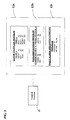
- the software architecture block diagram in Figure 3 illustrates how the programs collectively work to provide the functionality of the advent calendar 1.
- the computer processor 12 invokes each of the programs 12a-12c in the appropriate order.
- the calendar clock program 12a generally will be the first program invoked. Its function is to serve as the internal clock of the interactive device 10. More specifically, the clock calendar program 12a will set, keep and display the time of day and date of the interactive device 10.
- the clock calendar program 12a carries out the functions of a traditional clock and calendar, in that it records date and time and is adjustable.
- the daylight savings program 12b takes into account daylight savings, a time-related phenomenon that is observed in some parts of the world.
- the daylight savings program 12b takes into account the summer and winter solstice dates, upon the arrival of which the time of day is adjusted by one hour either forward or backward, respectively.
- the observance of daylight savings is not recognized worldwide; therefore the functionality may be disabled if inapplicable to a particular locale. If the winter and summer solstice dates are programmed, the clock calendar program 12a automatically adjusts itself accordingly based upon those appropriate dates.
- the daily alarm and announcement program 12c allows a user to specify an occasion on which to trigger an alarm or announcement. Events, such as birthdays, holidays, local seasons, religious holidays and events, and the like, may be programmed into the daily alarm and announcement program 12c. In the present embodiment, the daily alarm and announcement program 12c stores the relevant dates counting down the days to Christmas. Each alarm and announcement stored in the daily alarm and announcement program 12c is triggered when the clock calendar program 12a hits that target date or time.
- the daily alarm and announcement program 12c has a stored alarm for December 1 at 10:00 AM, upon the clock calendar program 12a reaching December 1 and 10:00 AM, the daily alarm and announcement program 12c generates, "Today is December 1, there are 24 days to Christmas, Open the first box of your advent Calendar.”
- the interactive device 10 may be programmed or adjusted ad hoc by the user, or come preprogrammed by the manufacturer.
- the user may program the interactive device 10 by utilizing the input means to set the values of the clock calendar program 12a the daylight savings program 12b, and the daily alarm and announcement program 12c.
- the computer processor 12, internal battery 14, input means and output means are seamlessly integrated within the interactive device 10.
- the requisite functional components of the interactive device 10 are designed to be minimally obstructive.
- a person having ordinary skill in the art would understand that the functional components of the interactive device 10 may be positioned in a variety of formats, so long as they do not disparage the creative appeal of the interactive device 10.
- the input means may comprise buttons or switches 16a, 16b strategically positioned in the paw and ear of the toy and the output means is an internal speaker 18.
- the input switches 16a, 16b are used for the input of values and the activation of programs 12a-12c in the interactive device 10, as will be discussed in more detail below.
- the interactive device 10 also includes a three position switch (not shown) located at the compartment for the internal battery 14, such switch being used to turn the interactive device 10 on and off and also to optionally place the interactive device 10 into either a "try-me” mode or a "play” mode.
- the output means may be an internal speaker 18, which generates audible messages to the user.
- Figure 4 illustrates the schematics of the interactive device 10.
- the input switches 16a, 16b (corresponding to respective ones of SW3 and SW2) are used for the input of values and for the activation of programs 12a-12c, as indicated above.
- Figure 5 schematically depicts the interactive device 10 utilizing an infrared receiver 22a as an input means. It is contemplated that a person having ordinary skill in the art would understand that, a user may input values into an interactive device 10 by operating a device which has infrared transmission capability. It is also contemplated that in this alternative embodiment, the interactive device 10 may be provided with and infrared transmitter 22b that allows the interactive device 10 to transmit data to another device, the combined functionality of the receiver 22a and transmitter 22b being in accordance with the teachings of U.S. Patent No. 7,068,941 entitled Interactive Talking Dolls.
- the output means may be an audio or visual display, such as a display screen or the like.
- the input and output means are likely to vary in accordance with the design and functionality of the interactive device 10.
- the switches 16a, 16b and the internal speaker 18 are advantageous to design the switches 16a, 16b and the internal speaker 18 to conform to the design of the teddy bear.
- the interactive device 10 may be outfitted with a transmitter and receiver which allow for the transmission, reception and synchronization of data information through the use of radio frequency (RF) rather than through the use of infrared as occurs through the use of the infrared receiver 22a and the infrared transmitter 22b.
- RF radio frequency
- FIG. 3 depicts the data structure of the programs 12a-12c of the computer processor 12.
- the clock calendar program 12a generally comprises date 24 and time 26 fields.
- the date 24 and time 26 serve as the internal clock and calendar of the interactive device 10 and are adjustable at anytime.
- the clock calendar program 12a is preprogrammed to default to "January" in the month field 24a. Therefore, when setting the month, the internal speaker 18 generates the word "January” to indicate the value that is currently selected in that field 24a.
- the user may increment the month by pushing the 'ear' switch 16b and upon reaching the desired month, the user may set the month by pushing the 'paw' switch 16a.
- the day field 24b defaults to the first day of the month "01", and accordingly, the program generates a "one" via the internal speaker 18.
- the user may increment the value in the day field 24b by pushing the ear switch 16b and subsequently set the day by pushing the paw switch 16a.
- the year field is preprogrammed to default to the present year. By utilizing the input buttons 16a, 16b the user may toggle to and set the desired year.
- the time fields 26 are set in a similar manner as the date fields 24.
- the time 26 is set to hour 26a, minute 26b, second 26c and AM/PM 26d.
- the user may adjust the date 24 or time 26 at anytime by toggling the input switches 16a, 16b.
- the user may set or enter the interactive device 10 into a "sleep" mode or power conservation mode, and yet still retain the values set in programs 12a-12c.
- the interactive device 10 may also automatically enter itself into the "sleep" mode or power conservation mode if it is not being activated or used for a certain period of time, and yet still retain the values set in programs 12a-12c.
- the daylight savings program 12b generally comprises a data structure that stores a summer solstice date 28 and a winter solstice date 30.
- the user may input values in the daylight savings program 12b by setting the date fields 28, 30 of the summer and winter solstices.
- the dates 28, 30 are set in a similar manner, as was the date in the clock calendar program 12a by manipulating the input switches 16a and 16b. Since daylight savings is not observed universally, the user may turn this functionality off if so desired. Selecting "NO" in the month fields 28a, 30a and the day fields 28b, 30b disables the daylight savings functionality.
- the daylight savings program 12b can come preprogrammed to default a particular month or day. However, the user may populate the fields to adjust the dates for different parts or areas of the world.
- the daily alarm and announcement program 12c generally comprises a data structure that stores a function field 32 and setting fields 34a, 34b.
- the function field 32 stores particular alarms or announcements indicative of an event.
- the setting fields 34a, 34b store the date and time the function field 32 is activated.
- the function field 32 is not open to being adjusted or altered. However, manipulating the setting fields 34a, 34b may disable the functionality stored within the function field 32.
- the daily alarm and announcement program 12c comes preprogrammed with the functionality and correlating library of sounds relative to an Arts calendar such as the exemplary Arts calendar 1. Once the clock calendar program 12a has reached an anticipated date 34a and time 34b as prescribed by the daily alarm and announcement program 12c, the program will initiate the play of specific messages 32.
- the interactive device 10 will speak or broadcast messages to communicate the anticipation of the holiday event at whatever time the daily alarm and announcement program 12c calls for. For example, upon each day of December between December I and December 25, a response is generated from the daily alarm and announcement program counting down the days to Christmas, December 25.
- the daily alarm and announcements program 12c is capable of being programmed with a variety of functions 32 in anticipation of upcoming holidays or events. It is contemplated that in another embodiment of the present invention, functions 32 may be inputted to the interactive device 10 through software or by downloading content via the Internet. The manufacturer or third parties may provide functions 32 to store within the daily alarm and announcement program 12c on a fee basis or through software updates.
- the interactive device 10 is strategically fitted with a motor 10a and a series of switches 10b and actuators that enable the interactive device 10 to mimic human action by moving its arms and legs, turning its head, opening its mouth, and flashing lights 10c in response to the daily alarm and announcement program 12c.
- the switches 10b are generally factory settable (or selectable).
- the physical actions of the interactive device 10 are specific such that they are activated according to a particular event.
- the internal speaker 18 emits messages while the mouth is moving, thereby giving the appearance that the interactive device 10 is directly speaking messages to the user. Consumers are generally drawn towards toys that mimic human actions. Therefore, the creativity of the interactive device 10 enhances the marketable appeal of the toy.
- the switch SW6 shown in Figures 4 and 5 is a selection switch only needed by the manufacturer of the interactive device 10, such switch SW6 normally being open and optionally used by the manufacturer to assess the accuracy of the internal clock of the interactive device 10.
- multiple interactive devices 10 may come preprogrammed and time synchronized by the manufacturer such that the clock and calendar program 12a of each interactive device 10 may run at exactly the same date 24 and the same time 26. This results in the interactive devices 10 being capable of generating responses in unison.
- the manufacturer programs the interactive device 10 by utilizing a setup module 20, as illustrated in Figures 2 , 6-8 .
- the setup module 20 is an operative device that is communicable with the interactive device 10.
- the setup module 20 programs the interactive device 10 by inputting parameters into the clock calendar program 12a, the daylight savings program 12b, and the daily alarm and announcements program 12c.
- setup module 20 synchronizes the date 24 and time 26 of multiple interactive devices 10 such that each interactive device 10 may run at exactly the same date 24 and the same time 26. Therefore, the interactive devices 10 will activate any functions 32 stored in the daily alarm and announcements program 12c in unison.
- the setup module 20 comprises a computer processor 36, an internal battery 38, an electronic display screen 40, a connection means, an input means, and an internal speaker 50.
- the functionality of the setup module 20 may also be embodied as software, provided that the device (e.g., a personal computer) running such software is capable of being connected to the interactive device 10 in a manner which will be discussed in more detail below.
- the computer processor 36 runs a series of programs that load the interactive devices 10 with requisite values and parameters.
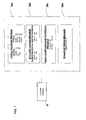
- Figure 7 depicts a software architecture block diagram illustrating the relationship between the setup module's programs.
- the computer processor 36 runs a clock calendar program 36a, a daylight savings program 36b, a daily alarm and announcements program 36c, and a margin of error program 36d.
- the clock calendar program 36a, daylight savings program 36b, and daily alarm and announcement program 36c carry the same logic and data structure as do their counterpart programs 12a-12c that run in the interactive device 10.
- the margin of error program 36d stores a measurement of time 52 that serves as an acceptable deviation between the time 26 of the interactive device and the time 56 of the setup module.
- the input means of the setup module 20 may comprise various buttons 42, 44, 46, 48 to input data.
- the input buttons 42, 44, 46, 48 are disposed upon the setup module.
- Data may be inputted into the setup module 20 through wireless technology.
- Figure 8 illustrates the schematics of a setup module 20 configured with an infrared receiver 58a as an input means. It is contemplated that a person having ordinary skill in the art would understand that a user may input data into the setup module 20 by operating a device which has infrared transmission capability.
- the setup module 20 may be provided with and infrared transmitter 58b that allows the setup module 20 to transmit data to an interactive device 10, the combined functionality of the receiver 58a and transmitter 58b also being in accordance with the teachings of U.S. Patent No. 7,068,941 mentioned above.
- the setup module 20 may be outfitted with a transmitter and receiver which allow for the transmission, reception and synchronization of data information through the use of radio frequency (RF) rather than through the use of infrared as occurs through the use of the infrared receiver 58a and the infrared transmitter 58b.
- RF radio frequency
- the setup module 20 has a setup configuration mode and a test configuration mode.
- the setup configuration mode permits desired values to be entered into the programs 36a-36d.
- Figures 9-12 illustrate screen shots of the display screen 40 while the setup module 20 is in a setup configuration mode and entering data into each program 36a-36d.
- the display button 48 toggles between the displays of different programs.
- the [K2] button 44 selects a target program 36a-36d, while the [KI] button 42 is depressed repeatedly until the correct data is displayed on the display screen 40 and then the [K2] button 44 is depressed again for confirmation and input of data into respective programs and fields.
- the calendar clock program 36a is capable of carrying out the functions of a traditional clock and calendar, in that it may record date 54 and time 56.
- the values inputted as the date 54 and time 56 will subsequently be the values stored in the interactive device 10 as date 24 and time 26.
- the date 54 and time 56 fields of the calendar clock program 36a of the setup module 20 are displayed upon the display screen 40.
- the date fields 54 include a year field 54c «YYYY», a month field 54a ( ⁇ MM>), a day field 54b ( ⁇ DD>), a day/number field 60 ( ⁇ DAY-#>), a Test/Setup field 62 ( ⁇ Test/Setup>).
- the time fields 56 include an hour field 56a ( ⁇ hh>), a minute field 56b ( ⁇ mm>), a second field 56c ( ⁇ ss>), and an AM/PM field 56d ( ⁇ AM/PM>).
- Parameters are inputted into a respective field when a cursor is flashing on that particular field.
- the year field 54c in order to program the year field 54c, the year field 54c must be flashing.
- the year can be incremented to future years by pushing the [K1] button 42.
- the manufacture can store the year by pushing the [K2] button 44.
- the month field 54a in order to input a month value, the month field 54a must be flashing.
- the month field 54a can be incremented to future months by pushing the [K1] button 42.
- the manufacturer can store the month by pushing [K2] button 44.
- the manufacturer would push the [K1] button 42 twice, upon doing so, "03" would be flashing in the month field. Subsequently, the manufacturer would push [K2] to set the month as March.
- the day field 54b In order to input values into the day field 54b, the day field 54b must be flashing. The day field 54b can be incremented by pushing the [K1] button 42. Upon reaching a desired day, the manufacturer can store the day by pushing the [K2] button 44.
- the day/number field 60 is populated with the day of the week and the correlated day number of that week.
- table I lists the days of the week and the corresponding day number: Table 1 Day of the week Day Number Monday 1 uesday 2 Wednesday 3 Thursday 4 Friday 5 Saturday 6 Sunday 7
- the corresponding day of the week and day number is displayed in the day/number field 60.
- the time fields 56 are set in a similar manner, as are the date fields 54.
- the time fields 56 include an hour field 56a, a minute field 56b, a second field 56c, and an AM/PM fleld 56d. Each respective field 56a-56d must be flashing in order to input data.
- the values may be incremented by pushing the [K1] button 42 and stored in the program by pushing the [K2] button 44.
- the Test/Setup field 62 is used as a moniker to distinguish whether the setup module 20 is in the setup configuration or the test configuration. In the test configuration, the setup module 20 can test to ensure that the settings of the interactive device 10 are in accordance to those of the setup module 20.
- the testing configuration's functionality is described in detail below. The user may toggle between the configurations by pushing the [K1] 42 button and subsequently set the configuration by pushing the [K2] 44 button.
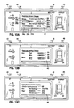
- Figures 10A and 10B illustrate screen shots of the display screen 40 while the daylight savings program 36b is in setup mode.
- the setup modes provides for a month field 64a, 66a and a day field 64b, 66b in which the user may input the date of the summer solstice and winter solstice. If the interactive device 10 is being shipped to a location that does not acknowledge daylight savings, a "00" may be entered in the month field 64a, 66a and day field 64b, 66b.
- Figure 10A illustrates a screen shot of the display screen 40 depicting the daylight savings program 36b receiving data in anticipation of the summer solstice, where time is pushed forward by one hour.
- the setup module 20 allows the user to enter the date 64 of the summer solstice into the month field 64a and day field 64b, to trigger the functionality of time being pushed forward by one hour on that day.
- Manipulating the [K1] 42 and [K2] 44 buttons sets the date 64.
- the displays screen 40 reads "Saving Fast" as indicative of the summer solstice.
- Figure 10B illustrates a screen shot of the display screen 40 depicting the daylight savings program 36b receiving data in anticipation of the winter solstice, where time is pushed back by one hour.
- the setup module 20 allows the user to enter the date 66 of the winter solstice into the month field 66a and day field 66b. On that particular date 66, the program 36b sets the time of the clock calendar program 36a one hour backward. The manipulation of the [K1] 42 and [K2] 44 buttons sets the date 66.
- the displays screen 40 reads "Saving Slow" as indicative of the winter solstice. However, it is understood that any moniker may distinctly be representative of the summer and winter solstices.
- Figures 11A and 11B illustrate screen shots of the display screen 40 while the daily alarm and announcement program 36c is in setup mode.
- the daily alarm and announcement program 36c allows a manufacturer to store particular occasions on which to trigger an alarm and announcement.
- Interactive devices 10 come preprogrammed by the manufacturer with a library or responses that correlate to the stored alarms and are triggered by the program on the appropriate day or in anticipation thereof.
- the daily alarm and announcement program 36c has a function field 68 and setting fields 70a, 70b.
- the function field 68 is representative of a particular response on an occasion.
- the function field 68 is set to "DEC AutoAnnounce", this particular function represents the logic of an Advent calendar like the Advent calendar I and automatically generates a December greeting at a prescribed date indicated by setting field 70a and a prescribed time indicated by the setting field 70b.
- the setting fields 70a, 70b can be populated with "NotSetting", as illustrated in FIG 11A . Otherwise, the setting fields 70a, 70b may be populated with the date and time representative of when the function should be triggered, as illustrated in FIG 11B .
- the daily alarm and announcements 36c program may store a multitude of response functions 68 that can be performed on multiple dates 70a.
- Figures 12 illustrates a screen shot of the display screen 40 while the margin of error program 36d is in a setup configuration.
- the margin of error program 36d has an Error Value field 52.
- the Error Value field 52 stores a measurement of time that represents an acceptable deviation between the time 56 of the setup module and the time 26 of the interactive devices. Oftentimes it is tedious and difficult to time synchronize devices within fractions of seconds. It is normal practice for a two time synchronized devices to have an acceptable deviation in time. Therefore, manufacturers allot a particular measurement of time that is considered an acceptable deviation. It is generally preferred that the deviation in time be minute such that the consumers will not be cognizant of the time deviation.
- the Error Field 52 is measured by seconds. Therefore, if the Error Value field 52 were set at '2', the setup module 20 would accept a two second deviation between the time 56 set in the setup module and the time 26 set in the interactive device 10.
- the setup module 20 programs and time synchronizes an interactive device 10 through a connection.
- a connection is established via the connection means.
- Figure 2 illustrates the setup module 20 as being connected to an interactive device 20 by employing a hard wire or cable 72a as the connection means.
- the cable 72a is coupled into a jack 72b that is embedded within the interactive device 10 by a three-prong connector 72c that is coupled to the distal end of the cable 72a.
- the three prongs of the connector 72c correspond to the three outputs collectively labeled with the reference number 72d in Figures 6 and 8 .
- the jack 72b is strategically placed in a discreet manner as to not compromise the aesthetic design of the interactive device 10.
- Figures 5 and 8 illustrate an embodiment of the present invention where the setup module 20 and the interactive device 10 can be communicable via infrared technology 22a, 22b, 58a, 58b as an alternative to the use of the cable 72a.
- the jack 72b may be substituted with an infrared transceiver which may communicate with a corresponding infrared transceiver of the setup module 20.
- the functionality of the setup module 20 may also be embodied as software, provided that the device (e.g., a personal computer) running such software is capable of being connected to the jack 72b of the interactive device 10.
- connection may be facilitated by cable like the cable 72a which has the connector 72c at one end thereof and a USB connector connectable to a USB port of the personal computer at the other end thereof.
- the jack 72b embedded in the interactive device 10 can be substituted or replaced with a USB-port jack for connection with a standard USB-port cable.
- the setup module 20 programs the interactive device 10 by setting the values in the clock calendar program 12a, daylight savings program 12b, and daily alarm and announcement program 12c.
- the SET/TEST button 46 initiates the data transfer.
- the setup module 20 also possesses a testing capability by which it ensures that the values stored in the interactive device 10 are in accordance to those set in the setup module 20.
- Figures 13A-13C depict screen shots of the setup module 20 in a testing configuration. More specifically, the display screen 40 is depicting the values entered in the programs 36a-36c of the setup module 20 set against the values of programs 12a-12c of the interactive device 10.
- the display button 48 toggles between each program. The manufacturer may visually check that each parameter is in accordance with the desired policy, or the manufacturer may trigger the automated testing function of a setup module 20 by pushing the SET/TEST button 46.
- Figure 14 is a flowchart depicting the testing logic employed by the setup module 20 in an automated testing configuration.
- the setup module 20 initially reads the date 24 and time 26 as set in the clock calendar program 12a of the interactive device 10. Subsequently at S20, the setup module 20 assess whether the date 24 matches the date field 54 as set in the setup module 20. If the date 24 is not in accordance with setup module 20, the setup module 20 will generate a FAIL message, indicated at step S30. When a FAIL message is triggered, the display screen 40 highlights the incorrect value, and illuminates a red light 74 on the setup module 20. In addition, the setup module 20 generates an audible alarm alerting the manufacturer that a FAIL message has been triggered.
- the setup module 20 will continue S40 to check the time 26 of the interactive device with the time 56 stored in the setup module 20. If the times 26, 56 are not in accordance, the process continues S50 by deducing the difference in times with the value as set in the margin of error field 52. If the difference in time is not an acceptable deviation as set forth in the setup module 20, a FAIL message will generate, as indicated at S60. If, however, times 26, 56 are in accordance, S50 is skipped, and the process continues with S70.
- the process continues S70 by reading the dates 28, 30 set in the daylight savings program 12b of the interactive device 10.
- the process continues S80 by checking the summer and winter solstice dates 28, 30 against the relative dates 64, 66 as set in the setup module 20. In this regard, if the summer and winter solstice dates 28, 30 are not in accordance with those set in the setup module 20, a FAIL message is triggered, as depicted by S90. If the summer and winter solstice dates 28, 30 are in accordance, the process continues S100 by reading parameters set in the daily alarm and announcements program 12c of the interactive device 10.
- the process continues S110, by the setup module 20 assessing that the function field 32 and setting fields 34a, 34b (illustrated in Figure 3 ) are set in accordance to their relative fields 68, 70a, 70b as set in the setup module 20. If the values are not in accordance, a FAIL message is triggered, as depicted in S120. If the values are in accordance, a PASS message is generated as depicted in S130. A PASS message indicates that the interactive device 10 has been satisfactorily programmed in accordance to the values set in the setup module 20. When the PASS message is generated, the display screen 40 indicates the test was successful, and a green light 76 is illuminated upon the setup module 20.
- the setup module 20 generates an audible alarm alerting the manufacturer that the interactive device 10 has successfully passed the test.
- the setup module 20 After multiple interactive devices 10 are programmed and time/date synchronized through the use of the setup module 20, it is contemplated that some very small, downstream deviation in the time settings of such interactive devices 10 may ultimately occur, such deviation being attributable to the internal clocks of the interactive devices 10 being run at a lower oscillation frequency and a lower power level to maximize the life of the on-board battery.
- the setup module 20 is capable of time synchronizing multiple interactive devices 10 such that their clock calendar programs 12a read the same time 26.
- Figure 15 is a flowchart depicting a series of interactions between a setup module 20 and multiple interactive devices 10, such that each interactive device 10 is time synchronized.
- the method begins at S200 by inputting the requisite parameters into the setup module 20. This includes the obligatory values set in the calendar clock program 36a, the daylight savings program 36b, the daily alarm and announcements program 36c, and the margin of error program 36d.
- the values that are initially programmed into the setup module 20 will be transferred into the programs 12a-12c of the interactive devices 10.
- the method continues by establishing a connection S210 between the setup module 20 and a first interactive device 10. Subsequently, the method continues S220 by pushing the SET/TEST button 46 to initiate a data transfer between the setup module 20 and the first interactive device 10.
- the method continues S230 by utilizing the setup module 20 to test the first interactive device 10, ensuring that the transferred values are in accordance with the values as set in the setup module 20.
- the method continues at S240 by pushing the SET/TEST button 46 to initiate the testing sequence as described above and illustrated in Figure 14 .
- the method continues at S250 by checking the results of the testing sequence. If the test was unsuccessful S260, indicating a discrepancy between the data set in the first interactive device 10 and the setup module 20, the method continues by performing steps S220-S240 again.
- a successfully tested first interactive device 10 is now programmed with the parameters stored in the setup module 20.
- the time 26 as set in the calendar clock program 12a is precisely the same as the time 56 set in the setup module 20. Therefore, the first interactive device 10 is time synchronized in accordance to the setup module 20.
- the method continues at S280 by connecting a second interactive device 10 to the setup module 20 and performing steps S220-S250.
- steps S20-S250 Upon a successful data transfer S270 into the second interactive device 10, both first and second interactive devices 10 are time synchronized with respect to each other and the setup module 20.
- the structural and functional attributes of the interactive device 10 considered in combination with those of the setup module 20 allows a plurality of interactive devices 10 to be programmed (e.g., time synchronized) in a manner which allows such interactive devices 10 to generate a prescribed response at the same time. It is contemplated that the particular time at which the response is generated will correspond to the ultimate shipment destination of the interactive devices 10 which is typically known by the manufacturer at the time and point of origin of manufacture. In view of this functionality, the interactive devices 10 may be more marketable to consumers when viewed upon a retail shelf while generating audio and/or visual messages in concert.
- each such interactive device 10 may be alleviated from the burden of having to undertake a time consuming, difficult programming task as would otherwise be needed to cause the interactive device 10 to function in the desired manner.
- the time and date data of each interactive device 10 may optionally be "customized" by an end purchaser, the time and date data initially input into the device 10 at the point of origin, which as indicated above is preferably destination specific, does not mandate such customization in order to achieve a requisite level of functionality.
- This functionality enhances the marketability and appeal of the interactive device 10 since the time and date data is onboard the interactive device 10 while on a store shelf without the need for any retailer or end user involvement.
- an exemplary protocol which may be implemented by an end user to facilitate the manual programming of an interactive device 10 is shown in the flowchart of Figure 16 .
Landscapes
- Physics & Mathematics (AREA)
- General Physics & Mathematics (AREA)
- Electric Clocks (AREA)
- Toys (AREA)
Claims (15)
- Interaktive Vorrichtung (10), die umfasst:einen Speicher;einen Computerprozessor (12), der mit dem Speicher verbunden ist, wobei der Computerprozessor (12) zum Ausführen eines Softwareprogramms, das ein Uhrzeit-Kalender-Programm (12a) enthält, betreibbar ist, wobei damit zugeordnete Zeit- und Datumsdaten in dem Speicher gespeichert sind;eine elektrische Leistungsquelle zum Bereitstellen von Leistung für die interaktive Vorrichtung (10);eine Eingabevorrichtung, die mit dem Computerprozessor (12) verbunden ist, wobei die Eingabevorrichtung von einem entsprechenden Uhrzeit-Kalender-Programm (36a), das in einer externen Quelle ausgeführt wird, Aktualisierungen mit Zeit- und Datumsdaten empfangen kann;undeine Ausgabevorrichtung, die mit dem Computerprozessor (12) verbunden ist, wobei durch das Uhrzeit-Kalender-Programm (12a) an der Ausgabevorrichtung eine Ausgabe erzeugt werden kann, die einem bestimmten Wert der Zeit- und/oder Datumsdaten entspricht;wobei das Uhrzeit-Kalender-Programm (12a) die Zeit- und/oder Datumsdaten aktiv unterhält; wobei der Speicher dafür ausgelegt ist, die Zeit- und/oder Datumsdaten auf eine Weise zu speichern, dass sie durch ein Installationsprogramm der externen Quelle gelesen werden können, um die Zeit- und/oder Datumsdaten zu testen, um eine Ausgabe und/oder eine Aktualisierung der Zeit- und/oder Datumsdaten, die in dem Speicher gespeichert sind, auszulösen, falls die Zeit- und/oder Datumsdaten, die in dem Speicher gespeichert sind, nicht gleich gegenwärtigen Zeit- und/oder Datumsdaten sind, die in der externen Quelle gespeichert und aktiv unterhalten werden.
- Interaktive Vorrichtung (10) gemäß Anspruch 1, bei der die elektrische Leistungsquelle eine interne Batterie (14) ist, die innerhalb der interaktiven Vorrichtung (10) aufgenommen ist.
- Interaktive Vorrichtung (10) gemäß Anspruch 1, bei der die Eingabevorrichtung (10):- ein Infrarotempfänger (22a) ist, der mit dem Computerprozessor (12) elektrisch verbunden ist, oder- wenigstens zwei Eingangs/Ausgangs-Anschlüsse umfasst, die mit dem Computerprozessor (12) elektrisch verbunden sind, oder- ein Hochfrequenztransceiver (HF-Transceiver) ist.
- Interaktive Vorrichtung (10) gemäß Anspruch 1, bei der das Softwareprogramm enthält:- ein Sommerzeitprogramm (12b), das durch den Computerprozessor (12) ausgeführt wird und das zum Einstellen der Zeit, um sie zum Datum der Sommersonnenwende eine Stunde vorzustellen und zum Datum der Wintersonnenwende eine Stunde nachzustellen, betreibbar ist, oder- ein Programm (12c) für täglichen Alarm und Ankündigungen, das durch den Computerprozessor (12) ausgeführt wird und das dazu betreibbar ist, irgendeine von mehreren gespeicherten Funktionen an einem entsprechenden gespeicherten Einstellungsdatum zu einer entsprechenden gespeicherten Einstellungszeit zu aktivieren, wobei das Programm (12c) für täglichen Alarm und Ankündigungen vorzugsweise die Funktionalität eines Adventkalenders speichert.
- System zum Installieren mehrerer interaktiver Vorrichtungen (10), wobei das System ein Installationsmodul (20) enthält, das umfasst:einen Speicher;eine elektrische Leistungsquelle;einen Computerprozessor (36), der ein Installationssoftwareprogramm ausführt, das ein Installations-Uhrzeit-Kalender-Programm (36a) enthält, wobei die Installations-Zeit- und -Datumsdaten durch das Installations-Uhrzeit-Kalender-Programm (36a), das in dem Speicher gespeichert ist, aktiv unterhalten werden;eine Eingabevorrichtung, die mit dem Computerprozessor (36) verbunden ist, wobei über die Eingabevorrichtung aktualisierte Zeit- und Datumsdaten empfangen werden und an das Installations-Uhrzeit-Kalender-Programm (36a) gesendet werden;ein Datenkommunikationsmodul, das mit dem Computerprozessor (36) verbunden ist und mit wenigstens einer der mehreren interaktiven Vorrichtungen (10) verknüpft werden kann, wobei die aktualisierten Zeit- und Datumsdaten an die eine der mehreren interaktiven Vorrichtungen (10) zur Speicherung und Unterhaltung darin übertragen werden; wobei der Prozessor (36) des Installationsmoduls (20) die in einer der mehreren interaktiven Vorrichtungen (10) gespeicherten Zeit- und/oder Datumsdaten testet und dafür betreibbar ist, eine Ausgabe und/oder Aktualisierung der in der einen der mehreren interaktiven Vorrichtungen (10) gespeicherten Zeit- und/oder Datumsdaten zu erzeugen, falls die in der einen der mehreren interaktiven Vorrichtungen (10) gespeicherten Zeit- und Datumsdaten nicht gleich der gegenwärtigen Installationszeit und dem gegenwärtigen Installationsdatum, die durch den Computerprozessor (36) des Installationsmoduls (20) gespeichert und aktiv unterhalten werden, sind.
- System gemäß Anspruch 5, bei dem die elektrische Leistungsquelle eine interne Batterie (38) zum Zuführen von Leistung dazu zu dem Installationsmodul (20) ist.
- System gemäß Anspruch 5, bei dem das Datenkommunikationsmodul ein Infrarotsender (58b) ist, der mit dem Computerprozessor (36) des Installationsmoduls (20) elektrisch verbunden ist und mit einem entsprechenden Datenkommunikationsmodul der einen der mehreren interaktiven Vorrichtungen (10) verknüpft werden kann, wobei das Datenkommunikationsmodul ein Infrarotempfänger (22a) ist, der mit dem Computerprozessor (12) einer der mehreren interaktiven Vorrichtungen (10) elektrisch verbunden ist.
- System gemäß Anspruch 5, bei dem die Eingabevorrichtung- wenigstens zwei Schalter umfasst, die mit dem Computerprozessor (36) des Installationsmoduls (20) elektrisch verbunden sind, oder- ein Infrarotempfänger (58a) ist, der mit dem Computerprozessor (36) elektrisch verbunden ist, oder- ein Hochfrequenztransceiver (HF-Transceiver) ist.
- System gemäß Anspruch 5, das ferner umfasst:eine interne Schallerzeugungsvorrichtung, die ein Audiosignal erzeugt, das durch den Computerprozessor (36) des Installationsmoduls (20) ausgelöst wird.
- System gemäß Anspruch 5, bei dem das Installationssoftwareprogramm ein Fehlerspannenprogramm enthält, das durch den Computerprozessor (36) des Installationsmoduls (20) ausgeführt wird (36d), das zum Speichern eines Fehlerwertfelds betreibbar ist,
wobei das Fehlerfeld eine akzeptable Zeitabweichung zwischen den Zeit- und Datumsdaten, die in dem Speicher gespeichert sind, und den Zeit- und Datumsdaten, die in einer der mehreren interaktiven Vorrichtungen (10) gespeichert sind, speichert. - System gemäß Anspruch 10, bei dem der Computerprozessor (36) des Installationsmoduls (20) dafür konfiguriert ist, eine Ausgabe zu erzeugen, falls die Abweichung zwischen den in dem Speicher gespeicherten Zeit- und Datumsdaten und den in der einen der mehreren interaktiven Vorrichtungen (10) gespeicherten Zeit- und Datumsdaten größer als das Fehlerwertfeld ist.
- Verfahren zur Zeitsynchronisation interaktiver Vorrichtungen (10), die jede einen Computerprozessor (12) mit einem Speicher zum Speichern von Daten enthalten und zum Ausführen eines Softwareprogramms mit einem Uhrzeit-Kalender-Programm (12a) betreibbar sind, wobei das Verfahren die folgenden Schritte umfasst:a. Empfangen einer Installationszeit und eines Installationsdatums in einem Softwareprogramm mit einem entsprechenden Installations-Uhrzeit-Kalender-Programm (36a), das in einem Computerprozessor (36) eines Installationsmoduls (20) ausgeführt wird, wobei das Installations-Uhrzeit-Kalender-Programm (36a) zum Annehmen, Speichern und aktiven Unterhalten der gegenwärtigen Installationszeit und des gegenwärtigen Installationsdatums betreibbar ist;b. Verbinden einer Eingabevorrichtung einer ersten interaktiven Vorrichtung (10) mit einer Ausgabevorrichtung eines Installationsmoduls (20);c. Senden der gegenwärtigen Installationszeit und des gegenwärtigen Installationsdatums von dem Installationsmodul (20) an die erste interaktive Vorrichtung (10);d. Speichern der gegenwärtigen Installationszeit und des gegenwärtigen Installationsdatums in der ersten interaktiven Vorrichtung (10), wobei das Uhrzeit-Kalender-Programm (12a), das darin ausgeführt wird, zum Annehmen, Speichern und aktiven Unterhalten der gegenwärtigen Installationszeit und des gegenwärtigen Installationsdatums betreibbar ist;e. Testen der ersten interaktiven Vorrichtung (10) in der Weise, dass, falls die Zeit und das Datum, die in dem Computerprozessor (12) der ersten interaktiven Vorrichtung (10) gespeichert sind, nicht gleich der Installationszeit und dem Installationsdatum sind, der Computerprozessor (36) des Installationsmoduls (20) eine Ausgabe erzeugt;f. Verbinden einer Eingabevorrichtung einer zweiten interaktiven Vorrichtung (10) mit der Ausgabevorrichtung des Installationsmoduls (20);g. Übertragen der gegenwärtigen Installationszeit und des gegenwärtigen Installationsdatums an die zweite interaktive Vorrichtung (10) von dem Installationsmodul (20);h. Speichern der gegenwärtigen Installationszeit und des gegenwärtigen Installationsdatums in dem Computerprozessor (12) der zweiten interaktiven Vorrichtung (10), wobei das Uhrzeit-Kalender-Programm (12a), das darin ausgeführt wird, zum Annehmen, Speichern und aktiven Unterhalten der gegenwärtigen Installationszeit und des gegenwärtigen Installationsdatums betreibbar ist; undi. Überprüfen, dass die gegenwärtige Installationszeit und das gegenwärtige Installationsdatum, die in den Computerprozessoren (12) der ersten und der zweiten interaktiven Vorrichtung (10) gespeichert sind, innerhalb eines akzeptablen Abweichungsbereichs zu der gegenwärtigen Zeit und zu dem gegenwärtigen Datum passen, die in dem Computerprozessor (36) des Installationsmoduls (20) gespeichert sind.
- Interaktive Vorrichtung (10) gemäß Anspruch 1, die ferner eine weitere Eingabevorrichtung umfasst, die wenigstens zwei Schalter (16a, 16b) enthält, die mit dem Computerprozessor (12) elektrisch verbunden sind.
- Interaktives System gemäß Anspruch 5, bei dem die gegenwärtigen Zeit- und Datumsdaten in der Eingabevorrichtung für das Installationsmodul (20) für ein Zielgebietsschema spezifiziert werden.
- Interaktive Vorrichtung (10) gemäß Anspruch 1, bei der die interaktive Vorrichtung (10) ein Spielzeug ist, das einen Kopf und einem Mund aufweist, wobei die interaktive Vorrichtung (10) vorzugsweise mit wenigstens einem Motor, mit mehreren Aktuatoren und mit mehreren Schaltern, die einzeln und zusammen betreibbar sind, um den Kopf und den Mund des Spielzeugs in Übereinstimmung mit dem Softwareprogramm zu manipulieren, ausgestattet ist.
Applications Claiming Priority (2)
| Application Number | Priority Date | Filing Date | Title |
|---|---|---|---|
| US12/023,783 US8046620B2 (en) | 2008-01-31 | 2008-01-31 | Interactive device with time synchronization capability |
| PCT/US2009/031407 WO2009099750A2 (en) | 2008-01-31 | 2009-01-19 | Interactive device with time synchronization capability |
Publications (3)
| Publication Number | Publication Date |
|---|---|
| EP2243057A2 EP2243057A2 (de) | 2010-10-27 |
| EP2243057A4 EP2243057A4 (de) | 2011-10-26 |
| EP2243057B1 true EP2243057B1 (de) | 2013-03-20 |
Family
ID=40932903
Family Applications (1)
| Application Number | Title | Priority Date | Filing Date |
|---|---|---|---|
| EP09708899A Not-in-force EP2243057B1 (de) | 2008-01-31 | 2009-01-19 | Interaktive vorrichtung mit zeitsynchronisierungsvermögen |
Country Status (4)
| Country | Link |
|---|---|
| US (3) | US8046620B2 (de) |
| EP (1) | EP2243057B1 (de) |
| CN (1) | CN102007457B (de) |
| WO (1) | WO2009099750A2 (de) |
Families Citing this family (20)
| Publication number | Priority date | Publication date | Assignee | Title |
|---|---|---|---|---|
| US9274807B2 (en) * | 2006-04-20 | 2016-03-01 | Qualcomm Incorporated | Selective hibernation of activities in an electronic device |
| US8046620B2 (en) * | 2008-01-31 | 2011-10-25 | Peter Sui Lun Fong | Interactive device with time synchronization capability |
| US8583956B2 (en) * | 2008-01-31 | 2013-11-12 | Peter Sui Lun Fong | Interactive device with local area time synchronization capbility |
| CN101981530B (zh) * | 2008-04-11 | 2012-12-12 | 飞思卡尔半导体公司 | 具有低功率模式和非低功率模式的微处理器,数据处理系统和计算机程序产品 |
| US20090300143A1 (en) * | 2008-05-28 | 2009-12-03 | Musa Segal B H | Method and apparatus for interacting with media programming in real-time using a mobile telephone device |
| US20110130069A1 (en) * | 2009-12-01 | 2011-06-02 | Jill Rollin | Doll with alarm |
| CN102957771A (zh) * | 2011-08-31 | 2013-03-06 | 深圳富泰宏精密工业有限公司 | 闹钟设置方法及系统 |
| US20140039675A1 (en) * | 2012-08-03 | 2014-02-06 | Nimer Mohammed Ead | Instructional humanoid robot apparatus and a method thereof |
| CN104107547A (zh) * | 2012-12-08 | 2014-10-22 | 零售权威有限责任公司 | 无线控制的可动人偶 |
| WO2014189943A1 (en) * | 2013-05-22 | 2014-11-27 | Weatherford/Lamb, Inc. | Method and system for tracking movement trajectory of a pipeline tool |
| CN104244166A (zh) * | 2014-08-12 | 2014-12-24 | 广州三星通信技术研究有限公司 | 穿戴式设备的系统时间配置方法和装置 |
| USD780852S1 (en) | 2015-07-15 | 2017-03-07 | Gamblit Gaming, Llc | Interactive device for a user |
| USD780747S1 (en) | 2015-07-30 | 2017-03-07 | Gamblit Gaming, Llc | Interactive device for a user |
| CN108430555B (zh) | 2015-10-23 | 2022-06-14 | 费雪派克医疗保健有限公司 | 用于向使用者提供空气流的设备 |
| CN105619421A (zh) * | 2016-03-27 | 2016-06-01 | 绵阳晓迪圣点创意科技有限公司 | 时钟机器人 |
| JP6467674B2 (ja) * | 2016-07-20 | 2019-02-13 | Groove X株式会社 | スキンシップを理解する自律行動型ロボット |
| USD791887S1 (en) | 2016-07-25 | 2017-07-11 | Cheryl A. Freeman | Stuffed toy |
| CN106600938A (zh) * | 2017-01-23 | 2017-04-26 | 赵红领 | 智能睡眠引导闹铃 |
| JP2018137619A (ja) * | 2017-02-22 | 2018-08-30 | 大井電気株式会社 | 同期用無線装置 |
| US12414062B2 (en) * | 2020-03-31 | 2025-09-09 | Telefonaktiebolaget Lm Ericsson (Publ) | User equipment capabilities for time sensitive networking |
Family Cites Families (14)
| Publication number | Priority date | Publication date | Assignee | Title |
|---|---|---|---|---|
| US5677895A (en) | 1994-08-18 | 1997-10-14 | Mankovitz; Roy J. | Apparatus and methods for setting timepieces |
| US5752880A (en) * | 1995-11-20 | 1998-05-19 | Creator Ltd. | Interactive doll |
| CA2225060A1 (en) | 1997-04-09 | 1998-10-09 | Peter Suilun Fong | Interactive talking dolls |
| EP0991453A1 (de) * | 1998-04-16 | 2000-04-12 | Creator Ltd. | Interaktives spielzeug |
| US6554679B1 (en) * | 1999-01-29 | 2003-04-29 | Playmates Toys, Inc. | Interactive virtual character doll |
| WO2000074402A1 (en) * | 1999-05-28 | 2000-12-07 | Afx Technology Group International, Inc. | Wireless transceiver network employing node-to-node data messaging |
| US20020172095A1 (en) * | 2001-03-14 | 2002-11-21 | Pandipati Radha K.C. | Electric clocks and remote controller |
| US6705919B2 (en) * | 2002-01-08 | 2004-03-16 | Mattel, Inc. | Electronic amusement device with long duration timer |
| US7297044B2 (en) * | 2002-08-26 | 2007-11-20 | Shoot The Moon Products Ii, Llc | Method, apparatus, and system to synchronize processors in toys |
| US20040117858A1 (en) * | 2002-12-12 | 2004-06-17 | Boudreau Paul A. | Data enhanced multi-media system for an external device |
| US20060217967A1 (en) * | 2003-03-20 | 2006-09-28 | Doug Goertzen | System and methods for storing and presenting personal information |
| JP2009512019A (ja) * | 2005-10-06 | 2009-03-19 | ヴェルジェンス エンターテインメント エルエルシー, ア カリフォルニア リミテッド ライアビリティー カンパニー | 実質的に同時のアラートと、間欠的なコンテストにおけるその利用 |
| US20070128979A1 (en) * | 2005-12-07 | 2007-06-07 | J. Shackelford Associates Llc. | Interactive Hi-Tech doll |
| US8046620B2 (en) * | 2008-01-31 | 2011-10-25 | Peter Sui Lun Fong | Interactive device with time synchronization capability |
-
2008
- 2008-01-31 US US12/023,783 patent/US8046620B2/en not_active Expired - Fee Related
-
2009
- 2009-01-19 WO PCT/US2009/031407 patent/WO2009099750A2/en not_active Ceased
- 2009-01-19 EP EP09708899A patent/EP2243057B1/de not_active Not-in-force
- 2009-01-19 CN CN2009801109333A patent/CN102007457B/zh not_active Expired - Fee Related
-
2011
- 2011-09-20 US US13/237,138 patent/US8271822B2/en not_active Expired - Fee Related
-
2012
- 2012-08-17 US US13/588,933 patent/US9128469B2/en active Active
Also Published As
| Publication number | Publication date |
|---|---|
| US20130036321A1 (en) | 2013-02-07 |
| HK1149960A1 (en) | 2011-10-21 |
| WO2009099750A3 (en) | 2009-12-30 |
| US20090199034A1 (en) | 2009-08-06 |
| EP2243057A2 (de) | 2010-10-27 |
| US8271822B2 (en) | 2012-09-18 |
| US9128469B2 (en) | 2015-09-08 |
| CN102007457A (zh) | 2011-04-06 |
| US8046620B2 (en) | 2011-10-25 |
| CN102007457B (zh) | 2013-07-31 |
| EP2243057A4 (de) | 2011-10-26 |
| US20120030498A1 (en) | 2012-02-02 |
| WO2009099750A2 (en) | 2009-08-13 |
Similar Documents
| Publication | Publication Date | Title |
|---|---|---|
| US8046620B2 (en) | Interactive device with time synchronization capability | |
| US8583956B2 (en) | Interactive device with local area time synchronization capbility | |
| US6089942A (en) | Interactive toys | |
| US20160342311A1 (en) | Timer display and methods of communication between the timer display and a mobile device | |
| KR101008085B1 (ko) | 로봇 시스템, 로봇 장치 및 그 제어 방법 | |
| US20200372829A1 (en) | Reward Clock | |
| WO2018108175A1 (zh) | 可穿戴设备任务计划调整方法及设备 | |
| US10761486B2 (en) | Reward clock | |
| US20100052864A1 (en) | Light, sound, & motion receiver devices | |
| US10105287B2 (en) | System and method for remotely monitoring medication compliance using a pillbox with a camera | |
| US20040038620A1 (en) | Method, apparatus, and system to synchronize processors in toys | |
| WO2021247943A2 (en) | Programmable interactive systems, methods and machine readable programs to affect behavioral patterns | |
| US20170072329A1 (en) | A Dynamic Notification System Via A Product | |
| US20030125077A1 (en) | Multimedia watch | |
| HK1149960B (en) | Interactive device with time synchronization capability | |
| JP2017106872A (ja) | 装置及びプログラム | |
| HK1175871B (en) | Interactive device with local area time synchronization capability | |
| US8634278B1 (en) | Talking watch device | |
| JP7519711B2 (ja) | 装置及びプログラム | |
| CN209149093U (zh) | 一种儿童闹钟及儿童闹钟系统 | |
| US20120021731A1 (en) | Cloud computing system configured for a consumer to program a smart phone and touch pad | |
| CN109283834A (zh) | 一种儿童闹钟、控制方法及儿童闹钟系统 | |
| CN120166205A (zh) | 投影系统、投影装置以及控制投影装置的方法 | |
| CA2257060A1 (en) | Talking alarm clock | |
| CA2234330A1 (en) | Interactive toys |
Legal Events
| Date | Code | Title | Description |
|---|---|---|---|
| PUAI | Public reference made under article 153(3) epc to a published international application that has entered the european phase |
Free format text: ORIGINAL CODE: 0009012 |
|
| 17P | Request for examination filed |
Effective date: 20100826 |
|
| AK | Designated contracting states |
Kind code of ref document: A2 Designated state(s): AT BE BG CH CY CZ DE DK EE ES FI FR GB GR HR HU IE IS IT LI LT LU LV MC MK MT NL NO PL PT RO SE SI SK TR |
|
| AX | Request for extension of the european patent |
Extension state: AL BA RS |
|
| DAX | Request for extension of the european patent (deleted) | ||
| REG | Reference to a national code |
Ref country code: HK Ref legal event code: DE Ref document number: 1149960 Country of ref document: HK |
|
| A4 | Supplementary search report drawn up and despatched |
Effective date: 20110923 |
|
| RIC1 | Information provided on ipc code assigned before grant |
Ipc: G04G 5/00 20060101ALI20110919BHEP Ipc: A63H 3/00 20060101ALI20110919BHEP Ipc: A63H 30/00 20060101AFI20110919BHEP Ipc: G04G 7/02 20060101ALI20110919BHEP Ipc: G04G 21/04 20100101ALI20110919BHEP |
|
| 17Q | First examination report despatched |
Effective date: 20120522 |
|
| GRAP | Despatch of communication of intention to grant a patent |
Free format text: ORIGINAL CODE: EPIDOSNIGR1 |
|
| GRAS | Grant fee paid |
Free format text: ORIGINAL CODE: EPIDOSNIGR3 |
|
| REG | Reference to a national code |
Ref country code: DE Ref legal event code: R079 Ref document number: 602009014169 Country of ref document: DE Free format text: PREVIOUS MAIN CLASS: G04F0008000000 Ipc: A63H0003000000 |
|
| GRAA | (expected) grant |
Free format text: ORIGINAL CODE: 0009210 |
|
| AK | Designated contracting states |
Kind code of ref document: B1 Designated state(s): AT BE BG CH CY CZ DE DK EE ES FI FR GB GR HR HU IE IS IT LI LT LU LV MC MK MT NL NO PL PT RO SE SI SK TR |
|
| REG | Reference to a national code |
Ref country code: GB Ref legal event code: FG4D |
|
| RIC1 | Information provided on ipc code assigned before grant |
Ipc: G04G 21/04 20130101ALI20130213BHEP Ipc: A63H 3/00 20060101AFI20130213BHEP |
|
| REG | Reference to a national code |
Ref country code: CH Ref legal event code: EP |
|
| REG | Reference to a national code |
Ref country code: IE Ref legal event code: FG4D |
|
| REG | Reference to a national code |
Ref country code: AT Ref legal event code: REF Ref document number: 601688 Country of ref document: AT Kind code of ref document: T Effective date: 20130415 |
|
| REG | Reference to a national code |
Ref country code: DE Ref legal event code: R096 Ref document number: 602009014169 Country of ref document: DE Effective date: 20130516 |
|
| PG25 | Lapsed in a contracting state [announced via postgrant information from national office to epo] |
Ref country code: BG Free format text: LAPSE BECAUSE OF FAILURE TO SUBMIT A TRANSLATION OF THE DESCRIPTION OR TO PAY THE FEE WITHIN THE PRESCRIBED TIME-LIMIT Effective date: 20130620 Ref country code: SE Free format text: LAPSE BECAUSE OF FAILURE TO SUBMIT A TRANSLATION OF THE DESCRIPTION OR TO PAY THE FEE WITHIN THE PRESCRIBED TIME-LIMIT Effective date: 20130320 Ref country code: ES Free format text: LAPSE BECAUSE OF FAILURE TO SUBMIT A TRANSLATION OF THE DESCRIPTION OR TO PAY THE FEE WITHIN THE PRESCRIBED TIME-LIMIT Effective date: 20130701 Ref country code: LT Free format text: LAPSE BECAUSE OF FAILURE TO SUBMIT A TRANSLATION OF THE DESCRIPTION OR TO PAY THE FEE WITHIN THE PRESCRIBED TIME-LIMIT Effective date: 20130320 Ref country code: NO Free format text: LAPSE BECAUSE OF FAILURE TO SUBMIT A TRANSLATION OF THE DESCRIPTION OR TO PAY THE FEE WITHIN THE PRESCRIBED TIME-LIMIT Effective date: 20130620 |
|
| REG | Reference to a national code |
Ref country code: AT Ref legal event code: MK05 Ref document number: 601688 Country of ref document: AT Kind code of ref document: T Effective date: 20130320 |
|
| REG | Reference to a national code |
Ref country code: LT Ref legal event code: MG4D |
|
| PG25 | Lapsed in a contracting state [announced via postgrant information from national office to epo] |
Ref country code: GR Free format text: LAPSE BECAUSE OF FAILURE TO SUBMIT A TRANSLATION OF THE DESCRIPTION OR TO PAY THE FEE WITHIN THE PRESCRIBED TIME-LIMIT Effective date: 20130621 Ref country code: SI Free format text: LAPSE BECAUSE OF FAILURE TO SUBMIT A TRANSLATION OF THE DESCRIPTION OR TO PAY THE FEE WITHIN THE PRESCRIBED TIME-LIMIT Effective date: 20130320 Ref country code: FI Free format text: LAPSE BECAUSE OF FAILURE TO SUBMIT A TRANSLATION OF THE DESCRIPTION OR TO PAY THE FEE WITHIN THE PRESCRIBED TIME-LIMIT Effective date: 20130320 Ref country code: LV Free format text: LAPSE BECAUSE OF FAILURE TO SUBMIT A TRANSLATION OF THE DESCRIPTION OR TO PAY THE FEE WITHIN THE PRESCRIBED TIME-LIMIT Effective date: 20130320 |
|
| REG | Reference to a national code |
Ref country code: NL Ref legal event code: VDEP Effective date: 20130320 |
|
| PG25 | Lapsed in a contracting state [announced via postgrant information from national office to epo] |
Ref country code: BE Free format text: LAPSE BECAUSE OF FAILURE TO SUBMIT A TRANSLATION OF THE DESCRIPTION OR TO PAY THE FEE WITHIN THE PRESCRIBED TIME-LIMIT Effective date: 20130320 Ref country code: HR Free format text: LAPSE BECAUSE OF FAILURE TO SUBMIT A TRANSLATION OF THE DESCRIPTION OR TO PAY THE FEE WITHIN THE PRESCRIBED TIME-LIMIT Effective date: 20130320 |
|
| PG25 | Lapsed in a contracting state [announced via postgrant information from national office to epo] |
Ref country code: IS Free format text: LAPSE BECAUSE OF FAILURE TO SUBMIT A TRANSLATION OF THE DESCRIPTION OR TO PAY THE FEE WITHIN THE PRESCRIBED TIME-LIMIT Effective date: 20130720 Ref country code: SK Free format text: LAPSE BECAUSE OF FAILURE TO SUBMIT A TRANSLATION OF THE DESCRIPTION OR TO PAY THE FEE WITHIN THE PRESCRIBED TIME-LIMIT Effective date: 20130320 Ref country code: EE Free format text: LAPSE BECAUSE OF FAILURE TO SUBMIT A TRANSLATION OF THE DESCRIPTION OR TO PAY THE FEE WITHIN THE PRESCRIBED TIME-LIMIT Effective date: 20130320 Ref country code: CZ Free format text: LAPSE BECAUSE OF FAILURE TO SUBMIT A TRANSLATION OF THE DESCRIPTION OR TO PAY THE FEE WITHIN THE PRESCRIBED TIME-LIMIT Effective date: 20130320 Ref country code: AT Free format text: LAPSE BECAUSE OF FAILURE TO SUBMIT A TRANSLATION OF THE DESCRIPTION OR TO PAY THE FEE WITHIN THE PRESCRIBED TIME-LIMIT Effective date: 20130320 Ref country code: RO Free format text: LAPSE BECAUSE OF FAILURE TO SUBMIT A TRANSLATION OF THE DESCRIPTION OR TO PAY THE FEE WITHIN THE PRESCRIBED TIME-LIMIT Effective date: 20130320 Ref country code: PT Free format text: LAPSE BECAUSE OF FAILURE TO SUBMIT A TRANSLATION OF THE DESCRIPTION OR TO PAY THE FEE WITHIN THE PRESCRIBED TIME-LIMIT Effective date: 20130722 Ref country code: NL Free format text: LAPSE BECAUSE OF FAILURE TO SUBMIT A TRANSLATION OF THE DESCRIPTION OR TO PAY THE FEE WITHIN THE PRESCRIBED TIME-LIMIT Effective date: 20130320 |
|
| PG25 | Lapsed in a contracting state [announced via postgrant information from national office to epo] |
Ref country code: CY Free format text: LAPSE BECAUSE OF FAILURE TO SUBMIT A TRANSLATION OF THE DESCRIPTION OR TO PAY THE FEE WITHIN THE PRESCRIBED TIME-LIMIT Effective date: 20130320 Ref country code: PL Free format text: LAPSE BECAUSE OF FAILURE TO SUBMIT A TRANSLATION OF THE DESCRIPTION OR TO PAY THE FEE WITHIN THE PRESCRIBED TIME-LIMIT Effective date: 20130320 |
|
| REG | Reference to a national code |
Ref country code: HK Ref legal event code: GR Ref document number: 1149960 Country of ref document: HK |
|
| PLBE | No opposition filed within time limit |
Free format text: ORIGINAL CODE: 0009261 |
|
| STAA | Information on the status of an ep patent application or granted ep patent |
Free format text: STATUS: NO OPPOSITION FILED WITHIN TIME LIMIT |
|
| PG25 | Lapsed in a contracting state [announced via postgrant information from national office to epo] |
Ref country code: DK Free format text: LAPSE BECAUSE OF FAILURE TO SUBMIT A TRANSLATION OF THE DESCRIPTION OR TO PAY THE FEE WITHIN THE PRESCRIBED TIME-LIMIT Effective date: 20130320 |
|
| 26N | No opposition filed |
Effective date: 20140102 |
|
| PG25 | Lapsed in a contracting state [announced via postgrant information from national office to epo] |
Ref country code: IT Free format text: LAPSE BECAUSE OF FAILURE TO SUBMIT A TRANSLATION OF THE DESCRIPTION OR TO PAY THE FEE WITHIN THE PRESCRIBED TIME-LIMIT Effective date: 20130320 |
|
| REG | Reference to a national code |
Ref country code: DE Ref legal event code: R097 Ref document number: 602009014169 Country of ref document: DE Effective date: 20140102 |
|
| PG25 | Lapsed in a contracting state [announced via postgrant information from national office to epo] |
Ref country code: MC Free format text: LAPSE BECAUSE OF FAILURE TO SUBMIT A TRANSLATION OF THE DESCRIPTION OR TO PAY THE FEE WITHIN THE PRESCRIBED TIME-LIMIT Effective date: 20130320 Ref country code: LU Free format text: LAPSE BECAUSE OF FAILURE TO SUBMIT A TRANSLATION OF THE DESCRIPTION OR TO PAY THE FEE WITHIN THE PRESCRIBED TIME-LIMIT Effective date: 20140119 |
|
| REG | Reference to a national code |
Ref country code: CH Ref legal event code: PL |
|
| PG25 | Lapsed in a contracting state [announced via postgrant information from national office to epo] |
Ref country code: CH Free format text: LAPSE BECAUSE OF NON-PAYMENT OF DUE FEES Effective date: 20140131 Ref country code: LI Free format text: LAPSE BECAUSE OF NON-PAYMENT OF DUE FEES Effective date: 20140131 |
|
| REG | Reference to a national code |
Ref country code: IE Ref legal event code: MM4A |
|
| REG | Reference to a national code |
Ref country code: FR Ref legal event code: PLFP Year of fee payment: 7 |
|
| PG25 | Lapsed in a contracting state [announced via postgrant information from national office to epo] |
Ref country code: IE Free format text: LAPSE BECAUSE OF NON-PAYMENT OF DUE FEES Effective date: 20140119 |
|
| REG | Reference to a national code |
Ref country code: FR Ref legal event code: PLFP Year of fee payment: 8 |
|
| PG25 | Lapsed in a contracting state [announced via postgrant information from national office to epo] |
Ref country code: MT Free format text: LAPSE BECAUSE OF FAILURE TO SUBMIT A TRANSLATION OF THE DESCRIPTION OR TO PAY THE FEE WITHIN THE PRESCRIBED TIME-LIMIT Effective date: 20130320 |
|
| PG25 | Lapsed in a contracting state [announced via postgrant information from national office to epo] |
Ref country code: HU Free format text: LAPSE BECAUSE OF FAILURE TO SUBMIT A TRANSLATION OF THE DESCRIPTION OR TO PAY THE FEE WITHIN THE PRESCRIBED TIME-LIMIT; INVALID AB INITIO Effective date: 20090119 Ref country code: TR Free format text: LAPSE BECAUSE OF FAILURE TO SUBMIT A TRANSLATION OF THE DESCRIPTION OR TO PAY THE FEE WITHIN THE PRESCRIBED TIME-LIMIT Effective date: 20130320 |
|
| REG | Reference to a national code |
Ref country code: FR Ref legal event code: PLFP Year of fee payment: 9 |
|
| PGFP | Annual fee paid to national office [announced via postgrant information from national office to epo] |
Ref country code: FR Payment date: 20161229 Year of fee payment: 9 |
|
| PGFP | Annual fee paid to national office [announced via postgrant information from national office to epo] |
Ref country code: DE Payment date: 20170110 Year of fee payment: 9 |
|
| PGFP | Annual fee paid to national office [announced via postgrant information from national office to epo] |
Ref country code: GB Payment date: 20170118 Year of fee payment: 9 |
|
| PG25 | Lapsed in a contracting state [announced via postgrant information from national office to epo] |
Ref country code: MK Free format text: LAPSE BECAUSE OF FAILURE TO SUBMIT A TRANSLATION OF THE DESCRIPTION OR TO PAY THE FEE WITHIN THE PRESCRIBED TIME-LIMIT Effective date: 20130320 |
|
| REG | Reference to a national code |
Ref country code: DE Ref legal event code: R119 Ref document number: 602009014169 Country of ref document: DE |
|
| GBPC | Gb: european patent ceased through non-payment of renewal fee |
Effective date: 20180119 |
|
| PG25 | Lapsed in a contracting state [announced via postgrant information from national office to epo] |
Ref country code: DE Free format text: LAPSE BECAUSE OF NON-PAYMENT OF DUE FEES Effective date: 20180801 Ref country code: FR Free format text: LAPSE BECAUSE OF NON-PAYMENT OF DUE FEES Effective date: 20180131 |
|
| REG | Reference to a national code |
Ref country code: FR Ref legal event code: ST Effective date: 20180928 |
|
| PG25 | Lapsed in a contracting state [announced via postgrant information from national office to epo] |
Ref country code: GB Free format text: LAPSE BECAUSE OF NON-PAYMENT OF DUE FEES Effective date: 20180119 |