EP2242879B1 - Transport device of a textile machine - Google Patents
Transport device of a textile machine Download PDFInfo
- Publication number
- EP2242879B1 EP2242879B1 EP09713313.6A EP09713313A EP2242879B1 EP 2242879 B1 EP2242879 B1 EP 2242879B1 EP 09713313 A EP09713313 A EP 09713313A EP 2242879 B1 EP2242879 B1 EP 2242879B1
- Authority
- EP
- European Patent Office
- Prior art keywords
- transport device
- roller
- band
- drafting roller
- drafting
- Prior art date
- Legal status (The legal status is an assumption and is not a legal conclusion. Google has not performed a legal analysis and makes no representation as to the accuracy of the status listed.)
- Active
Links
- 239000004753 textile Substances 0.000 title claims description 7
- 238000009960 carding Methods 0.000 claims description 4
- 230000000712 assembly Effects 0.000 claims description 2
- 238000000429 assembly Methods 0.000 claims description 2
- 239000013013 elastic material Substances 0.000 claims description 2
- 229920002635 polyurethane Polymers 0.000 claims description 2
- 239000004814 polyurethane Substances 0.000 claims description 2
- 239000000835 fiber Substances 0.000 description 5
- 229920001971 elastomer Polymers 0.000 description 4
- 238000004140 cleaning Methods 0.000 description 2
- 210000001520 comb Anatomy 0.000 description 1
- 230000008878 coupling Effects 0.000 description 1
- 238000010168 coupling process Methods 0.000 description 1
- 238000005859 coupling reaction Methods 0.000 description 1
- 230000003670 easy-to-clean Effects 0.000 description 1
- 230000002452 interceptive effect Effects 0.000 description 1
- 230000007257 malfunction Effects 0.000 description 1
- 238000004519 manufacturing process Methods 0.000 description 1
- 230000010355 oscillation Effects 0.000 description 1
- 230000035939 shock Effects 0.000 description 1
Images


Classifications
-
- D—TEXTILES; PAPER
- D01—NATURAL OR MAN-MADE THREADS OR FIBRES; SPINNING
- D01G—PRELIMINARY TREATMENT OF FIBRES, e.g. FOR SPINNING
- D01G19/00—Combing machines
- D01G19/06—Details
- D01G19/14—Drawing-off and delivery apparatus
- D01G19/18—Roller, or roller and apron, devices, e.g. operating to draw-off fibres continuously
-
- D—TEXTILES; PAPER
- D01—NATURAL OR MAN-MADE THREADS OR FIBRES; SPINNING
- D01H—SPINNING OR TWISTING
- D01H5/00—Drafting machines or arrangements ; Threading of roving into drafting machine
- D01H5/18—Drafting machines or arrangements without fallers or like pinned bars
- D01H5/60—Arrangements maintaining drafting elements free of fibre accumulations
- D01H5/62—Non-rotary cleaning pads or plates; Scrapers
Definitions
- the present invention relates to a transport device of a textile machine, especially a combing machine.
- carding On a fibre processing line for the production of a yarn, after the initial phases of opening and cleaning the fibre, carding is performed by carding machines after which the fibre appears in the form of a web.
- the web or lap After processing on a lap winder where necessary, during which various separate webs are combined to form a lap, the web or lap is combed by a combing machine so as to produce a web in which the fibres are extremely parallel and clean.
- a combing machine downward of the combing device, provides a device for transporting the web, composed of a set of coupled rollers.
- Said transport device comprises a drafting group composed of coupled cylinders which the web passes through, moved so as to achieve a drafting of the web before being forwarded for subsequent processing.
- rollers of the drafting group have the tendency to retain on the surface some residues, generally composed of fibre filaments which detach themselves from the web, and of dirt.
- the transport device comprises a wiper group, positioned against the drafting roller, composed of a support rigidly attached to the combing machine, inside which is a rubber band, held in contact with the surface of the drafting roller.
- the rubber band gathers the residues accumulated on the same and detaches them from the surface of the roller.
- the known wiper groups show some malfunctions, due mainly to the tendency of the rubber band to stick inside its seat in the support, so that if, as often happens, it is unable to remove the residues from the surface of the roller, it creates structural interference with said roller which sometimes leads to the supports of the same breaking.
- a transport device of a textile machine according to the preamble of claim 1 is known from GB 2613223 A .
- the purpose of the present invention is to provides for a transport device of a textile machine according to claim 1, especially a combing machine, which overcomes the drawbacks mentioned and satisfies the aforesaid requirements.
- wiper group of a drafting roller of a combing machine will refer to a wiper group of a drafting roller of a combing machine, but such wiper group may also be utilised for drafting rollers on other textile machines such as a drafting frame or carding machine.
- reference numeral 1 denotes a transport device of the web W of a combing machine.
- the combing machine comprises a combing device, for example with rotating combs, into which a web or fibre lap is fed for combing and, downward of the combing device, said transport device 1 is positioned, to transport the web W downwardly from the combing machine.
- the web is driven by coupled rollers, passing through the opening between them.
- the transport device comprises at least one pressure roller, positioned over the web in transit.
- the transport device comprises a first pressure roller 2, a second pressure roller 4, a third pressure roller 6 and a fourth pressure roller 8, all positioned over the web in transit.
- the pressure rollers 2, 4, 6, 8 are connected to respective actuators 2a, 4a, 6a, 8a for example pneumatic, able to press the respective rollers against the web in transit.
- the transport device comprises sensors able to detect an external action contrary to the thrust direction of said actuators.
- said sensors comprise a micro switch built-in to the actuator, so as to detect the backward movement of the actuator piston.
- the combing machine also comprises a frame 10, hinged to the body so that when raised from the body access to the combing device or transport device inside the combing machine is enabled.
- the first, second and third pressure rollers 2, 4, 6 are joined to the frame 10 by means of the actuators 2a, 4a, 6a, attached to it.
- the transport device also comprises a first lower roller 12, parallel to and coupled with the first pressure roller 2, so as to be aligned vertically with it, that is in such a way that the direction of translation of the actuator piston 2a is the radial direction of said first lower roller 12.
- the transport device also comprises a second lower roller 14 and a third lower roller 16, parallel to the pressure rollers 2, 4, 6.
- the second lower roller 14 and the third lower roller 16 are alongside the pressure roller 4 and respectively side by side upwardly and downwardly of their rotation axis, to form the openings for transit of the web so that the web in transit between the said openings remains essentially in contact with the surface of the second pressure roller 4.
- the transport device 1 comprises in addition a main drafting roller 20, positioned underneath, alongside the third pressure roller 6 and the fourth pressure roller 8 to form the transit opening for driving the web.
- the main drafting roller 20 and the pressure rollers 6, 8 are reciprocally positioned so that the web in transit undergoes a curving of its path downwards.
- the lower rollers 12, 14, 16 and the main drafting roller 20 are motorised, that is they are connected to one or more motorizations which impose, directly or indirectly through kinematic chains, a desired speed of rotation to each.
- Said rotation speeds are such as to produce a drafting of the web, for instance between the first lower roller 12 and the second lower roller 14 and between the third lower roller 16 and the main drafting roller 20.
- the entity of the draft between the first lower roller 12 and the second lower roller 14 is much less than the entity of the draft between the third lower roller 16 and the main drafting roller 20, so much so that in the first case one usually speaks of pre-drafting and in the second of main drafting.
- the transport device 1 comprises in addition, a funnel 22, positioned downwardly of the main drafting roller 20, towards which the drafted web is driven and through which the web transits, condensing, before being fed onwards for subsequent processing.
- the combing machine also comprises aspiration devices positioned below the transport device, able to aspirate the residues.
- Said aspiration devices comprise an aspiration nozzle 29, positioned under the lower rollers 12, 14, 16.
- the transport device 1 also comprises at least one wiper group 30 coupled to a roller to gather and detach the surface residues from it.
- the wiper group is coupled to the first or second or third lower roller 12, 14, 16, or a number of wiper groups are provided, each coupled to a roller.
- the wiper group 30 is coupled to the main drafting roller 20.
- the wiper group 30 comprises a support 32 fitted with a seat 34 and a soft band 36, lodged in said seat 34.
- the seat is in the form of a channel and the band sits on the bottom of it.
- the band 36 is lodged inside the seat 34 with play.
- the thickness of the band 36 is less than the width of the seat, so that between the band and the seat there is play.
- the band 36 is made in rubber and has a lip 38 protruding from the seat 34, in contact with the surface of the main drafting roller 20.
- the lip 38 protrudes inclined in the direction of rotation of the main drafting roller 20, to drag over this without sticking or causing unwanted vibrations.
- the support 32 is oscillating and said wiper group comprises influencing devices able to constantly influence the support 32 to press the band 36 towards the surface of the main drafting roller 20.
- the wiper group 30 comprises a flange 40 for attachment to the body of the combing machine, while the support 32 is mounted in an oscillating manner to the flange 40 by means of the interposition of said influencing devices.
- the support 32 is mounted to the flange 40 so as to rotate around a rotation axis X, incident to a plane orthogonal to the rotation axis of the main drafting roller 20.
- the influencing devices comprise a torsion spring 42, by means of which the support 32 is hinged to the flange 40, so as to be constantly influenced to rotate in the direction bringing the band 36 against the surface of the main drafting roller 20.
- the torsion spring is composed of a cylinder in elastic material, for example polyurethane.
- the flange 40 has at least one slotted hole 44 to attach the flange to the body of the combing machine in an adjustable manner.
- the wiper group 30 comprises a pair of supports 32 and a pair of flanges 40, respectively hinged to each other and positioned close to the axial extremities of the main drafting roller 20.
- the band 36 is inserted in the seats 34 of each support 32, thereby lying on its extremities in the manner of a beam between two supports.
- the two flange-support assemblies are structurally independent in the same way as the action of the influencing means on each support is independent so that, to spontaneously move the band against the surface of the main drafting roller 20, one support is rotated more or less than the other in relation to its flange.
- this makes it possible to spontaneously accommodate the band in the seats of the supports and against the main drafting roller 20, absorbing dimensional tolerance of the band, assembly tolerance of the wiper group and any wear of the band itself.
- the web is driven by the transport device 1 and undergoes drafting between the first pressure roller 2 and last pressure roller 8.
- residues are accumulated and pile up composed mainly of filaments which have detached from the web and from dirt, interfering structurally with the rollers themselves.
- the band 36 of the wiper group is held against the main drafting roller 20, so that it easily gathers the residues, while the roller proceeds to rotate, detaching them from the surface.
- the lip is accessible to an operator who can easily clean it.
- the support 32 is attached to the body of the combing machine and has the seat 34 inside which the band 36 is lodged, with play.
- the thickness of the band 36 is less than the width of the seat 34, so that between the band and the seat there is play.
- the band comprises the lip 38, protruding from the seat 34 against the main drafting roller 20.
- the wiper group 30 comprises a spring 40, lodged in the seat 34 of the support 32, between the band 36 and the bottom of the seat 34.
- the spring 40 constantly influences the band 36 to hold it against the main drafting roller 20.
- the wiper group according to the present invention makes it possible to detach the residues from the drafting roller and, in the presence of residues resistant to detachment, easily absorbs the ensuing action of interference, preventing breakage of the parts involved or the significant warping of the band, which would entail poor functioning of the wiper group.
- the band naturally takes up position inside the seats of the supports, thereby helping to absorb the interference of the residues and facilitating assembly of the wiper group.
- the wiper group is easy to clean: it is, in fact, sufficient to rotate the support to bring the band into such a position that the lip is accessible and can therefore be cleaned of any residues accumulated.
- the wiper group is easy to repair; for example, after rotating the support the band can easily be removed without undergoing interference from other mechanical parts.
Landscapes
- Engineering & Computer Science (AREA)
- Textile Engineering (AREA)
- Mechanical Engineering (AREA)
- Preliminary Treatment Of Fibers (AREA)
- Spinning Or Twisting Of Yarns (AREA)
Description
- The present invention relates to a transport device of a textile machine, especially a combing machine.
- On a fibre processing line for the production of a yarn, after the initial phases of opening and cleaning the fibre, carding is performed by carding machines after which the fibre appears in the form of a web.
- After processing on a lap winder where necessary, during which various separate webs are combined to form a lap, the web or lap is combed by a combing machine so as to produce a web in which the fibres are extremely parallel and clean.
- Generally, a combing machine, downward of the combing device, provides a device for transporting the web, composed of a set of coupled rollers.
- Said transport device comprises a drafting group composed of coupled cylinders which the web passes through, moved so as to achieve a drafting of the web before being forwarded for subsequent processing.
- It has been found that rollers of the drafting group have the tendency to retain on the surface some residues, generally composed of fibre filaments which detach themselves from the web, and of dirt.
- The residues show a tendency to accumulate, significantly disturbing the drafting operations in that they interfere with the coupling of the drafting rollers.
- Often, the transport device comprises a wiper group, positioned against the drafting roller, composed of a support rigidly attached to the combing machine, inside which is a rubber band, held in contact with the surface of the drafting roller.
- As the drafting roller rotates, the rubber band gathers the residues accumulated on the same and detaches them from the surface of the roller.
- However, the known wiper groups show some malfunctions, due mainly to the tendency of the rubber band to stick inside its seat in the support, so that if, as often happens, it is unable to remove the residues from the surface of the roller, it creates structural interference with said roller which sometimes leads to the supports of the same breaking.
- A transport device of a textile machine according to the preamble of claim 1 is known from
GB 2613223 A - The purpose of the present invention is to provides for a transport device of a textile machine according to claim 1, especially a combing machine, which overcomes the drawbacks mentioned and satisfies the aforesaid requirements.
- The characteristics and advantages of the wiper group according to the present invention will be evident from the description below, made by way of a non-limiting example according to the attached figures, wherein:
-
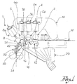
figure 1 shows a transport device of a combing machine, comprising a wiper group according to the present invention, in a functioning configuration; -
figure 1a shows an enlargement of a portion of the transport device infigure 1 ; -
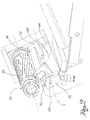
figure 2 shows a perspective view of a portion of the transport device infigure 1 ; -
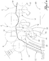
figure 3 shows the transport device infigure 1 , in a configuration of cleaning of the wiper group; -
figure 4 shows the transport device infigure 1 , in a configuration of replacement of the wiper group; and -
figure 5 shows a transport device of a combing machine, comprising a wiper group according to a further embodiment of the invention. - For clarity of exposition henceforth the description will refer to a wiper group of a drafting roller of a combing machine, but such wiper group may also be utilised for drafting rollers on other textile machines such as a drafting frame or carding machine.
- With reference to the attached figures, reference numeral 1 denotes a transport device of the web W of a combing machine.
- The combing machine comprises a combing device, for example with rotating combs, into which a web or fibre lap is fed for combing and, downward of the combing device, said transport device 1 is positioned, to transport the web W downwardly from the combing machine.
- In the transport device, the web is driven by coupled rollers, passing through the opening between them.
- The transport device comprises at least one pressure roller, positioned over the web in transit.
- For example, following the direction of transit of the web, the transport device comprises a
first pressure roller 2, asecond pressure roller 4, athird pressure roller 6 and afourth pressure roller 8, all positioned over the web in transit. - The
pressure rollers respective actuators - This way a pressure of the pressure rollers against the web in transit is actuated.
- Preferably, the transport device comprises sensors able to detect an external action contrary to the thrust direction of said actuators.
- For example said sensors comprise a micro switch built-in to the actuator, so as to detect the backward movement of the actuator piston.
- The combing machine also comprises a
frame 10, hinged to the body so that when raised from the body access to the combing device or transport device inside the combing machine is enabled. - Preferably, the first, second and
third pressure rollers frame 10 by means of theactuators 2a, 4a, 6a, attached to it. - The transport device also comprises a first
lower roller 12, parallel to and coupled with thefirst pressure roller 2, so as to be aligned vertically with it, that is in such a way that the direction of translation of theactuator piston 2a is the radial direction of said firstlower roller 12. - The transport device also comprises a second
lower roller 14 and a thirdlower roller 16, parallel to thepressure rollers - Preferably, the second
lower roller 14 and the thirdlower roller 16 are alongside thepressure roller 4 and respectively side by side upwardly and downwardly of their rotation axis, to form the openings for transit of the web so that the web in transit between the said openings remains essentially in contact with the surface of thesecond pressure roller 4. - The transport device 1 comprises in addition a
main drafting roller 20, positioned underneath, alongside thethird pressure roller 6 and thefourth pressure roller 8 to form the transit opening for driving the web. - The
main drafting roller 20 and thepressure rollers - The
lower rollers main drafting roller 20 are motorised, that is they are connected to one or more motorizations which impose, directly or indirectly through kinematic chains, a desired speed of rotation to each. - Said rotation speeds are such as to produce a drafting of the web, for instance between the first
lower roller 12 and the secondlower roller 14 and between the thirdlower roller 16 and themain drafting roller 20. - Preferably, the entity of the draft between the first
lower roller 12 and the secondlower roller 14 is much less than the entity of the draft between the thirdlower roller 16 and themain drafting roller 20, so much so that in the first case one usually speaks of pre-drafting and in the second of main drafting. - The transport device 1 comprises in addition, a
funnel 22, positioned downwardly of themain drafting roller 20, towards which the drafted web is driven and through which the web transits, condensing, before being fed onwards for subsequent processing. - Preferably, the combing machine also comprises aspiration devices positioned below the transport device, able to aspirate the residues.
- Said aspiration devices comprise an
aspiration nozzle 29, positioned under thelower rollers - The transport device 1 also comprises at least one
wiper group 30 coupled to a roller to gather and detach the surface residues from it. - According to embodiment variations, the wiper group is coupled to the first or second or third
lower roller - In the preferred embodiment, the
wiper group 30 is coupled to themain drafting roller 20. - The
wiper group 30 comprises asupport 32 fitted with aseat 34 and asoft band 36, lodged in saidseat 34. - For instance, the seat is in the form of a channel and the band sits on the bottom of it.
- The
band 36 is lodged inside theseat 34 with play. In other words the thickness of theband 36 is less than the width of the seat, so that between the band and the seat there is play. - Preferably, the
band 36 is made in rubber and has alip 38 protruding from theseat 34, in contact with the surface of themain drafting roller 20. - Preferably, the
lip 38 protrudes inclined in the direction of rotation of themain drafting roller 20, to drag over this without sticking or causing unwanted vibrations. - The
support 32 is oscillating and said wiper group comprises influencing devices able to constantly influence thesupport 32 to press theband 36 towards the surface of themain drafting roller 20. - According to the invention, the
wiper group 30 comprises aflange 40 for attachment to the body of the combing machine, while thesupport 32 is mounted in an oscillating manner to theflange 40 by means of the interposition of said influencing devices. - The
support 32 is mounted to theflange 40 so as to rotate around a rotation axis X, incident to a plane orthogonal to the rotation axis of themain drafting roller 20. - Preferably, in addition, the influencing devices comprise a
torsion spring 42, by means of which thesupport 32 is hinged to theflange 40, so as to be constantly influenced to rotate in the direction bringing theband 36 against the surface of themain drafting roller 20. - For instance, the torsion spring is composed of a cylinder in elastic material, for example polyurethane.
- According to a preferred embodiment, the
flange 40 has at least one slotted hole 44 to attach the flange to the body of the combing machine in an adjustable manner. - According to the embodiment shown, the
wiper group 30 comprises a pair ofsupports 32 and a pair offlanges 40, respectively hinged to each other and positioned close to the axial extremities of themain drafting roller 20. - The
band 36 is inserted in theseats 34 of eachsupport 32, thereby lying on its extremities in the manner of a beam between two supports. - Apart from the connection produced by the
band 36, which is in any case loose, the two flange-support assemblies are structurally independent in the same way as the action of the influencing means on each support is independent so that, to spontaneously move the band against the surface of themain drafting roller 20, one support is rotated more or less than the other in relation to its flange. - Advantageously this makes it possible to spontaneously accommodate the band in the seats of the supports and against the
main drafting roller 20, absorbing dimensional tolerance of the band, assembly tolerance of the wiper group and any wear of the band itself. - During the course of normal use of the combing machine, the web is driven by the transport device 1 and undergoes drafting between the
first pressure roller 2 andlast pressure roller 8. - During the course of processing, for example on the main drafting roller, residues are accumulated and pile up composed mainly of filaments which have detached from the web and from dirt, interfering structurally with the rollers themselves.
- The
band 36 of the wiper group, is held against themain drafting roller 20, so that it easily gathers the residues, while the roller proceeds to rotate, detaching them from the surface. - In the presence of residues which resist the action of the band, the oscillation of the support absorbs the ensuing shock, preventing sticking and breaking.
- To clean the wiper group, it is sufficient to rotate the
support 32, distancing thelip 38 of theband 36 from the main drafting roller 20 (figure 3 ). - This way, for example, the lip is accessible to an operator who can easily clean it.
- To perform replacement operations of the band, it is again sufficient to rotate the
support 32, distancing thelip 38 of theband 36 from themain drafting roller 20 and removing theband 36 from itsseats 34, before replacing it (figure 4 ). - According to the invention the
support 32 is attached to the body of the combing machine and has theseat 34 inside which theband 36 is lodged, with play. - In other words the thickness of the
band 36 is less than the width of theseat 34, so that between the band and the seat there is play. - The band comprises the
lip 38, protruding from theseat 34 against themain drafting roller 20. - In said embodiment variation, the
wiper group 30 comprises aspring 40, lodged in theseat 34 of thesupport 32, between theband 36 and the bottom of theseat 34. - The
spring 40 constantly influences theband 36 to hold it against themain drafting roller 20. - Innovatively, the wiper group according to the present invention makes it possible to detach the residues from the drafting roller and, in the presence of residues resistant to detachment, easily absorbs the ensuing action of interference, preventing breakage of the parts involved or the significant warping of the band, which would entail poor functioning of the wiper group.
- Advantageously moreover, the band naturally takes up position inside the seats of the supports, thereby helping to absorb the interference of the residues and facilitating assembly of the wiper group.
- According to a further advantageous aspect, the wiper group is easy to clean: it is, in fact, sufficient to rotate the support to bring the band into such a position that the lip is accessible and can therefore be cleaned of any residues accumulated.
- According to yet a further advantageous aspect, the wiper group is easy to repair; for example, after rotating the support the band can easily be removed without undergoing interference from other mechanical parts.
Claims (12)
- Transport device of a textile machine comprising:- at least one drafting roller (20);- a wiper group (30) comprising:- a pair of supports (32), each having a seat (34);- a band (36) extending mainly along the rotation axis of the drafting roller (20), able to lie against the surface of the drafting roller (20), at least partially lodged in said seats (34), wherein the supports (32) are supported in an oscillating manner to absorb the interference on the band of the residues accumulated on the drafting roller;- a pair of flanges (40) attached to the body of the textile machine, said supports (32) being respectively hinged to the flange (40), distanced along the rotation axis of the drafting roller;
characterised in that said at least one drafting roller (20) is coupled to a pressure roller (6) and in that said band (36) is lodged in the seats (34) of said supports (32) with play in the direction of the thickness inside the seat (34). - Transport device (1) according to claim 1, wherein, apart from the connection produced by the band (36), the two flange-support assemblies are structurally independent.
- Transport device (1) according to claim 1 or 2, wherein the support (32) is rotatable around an axis incident to a plane perpendicular to the rotation axis of the roller.
- Transport device (1) according to any of the previous claims, comprising influencing devices able to constantly influence the support (32) to press it so that the band (36) is held against the drafting roller.
- Transport device (1) according to claim 4, wherein the influencing means comprise a torsion spring, for example composed of a cylinder in elastic material, such as polyurethane
- Transport device (1) according to claim 3 and 5, wherein the support (32) is hinged to the flange (40) by means of said torsion spring.
- Transport device (1) according to any of the previous claims, wherein the band (36) comprises a lip (38) protruding from the seat (34), able to move against the drafting roller, said lip being inclined in the direction of rotation of the drafting roller.
- Transport device (1) according to any of the previous claims, comprising aspiration devices positioned under the drafting roller (20).
- Transport device (1) according to any of the previous claims, comprising an actuator (6a) able to press the pressure roller (6) towards the drafting roller (20), and sensor devices able to detect an action on the actuator piston contrary to the thrust direction.
- Combing machine comprising a transport device (1) made according to any of the previous claims.
- Drafting frame comprising a transport device (1) made according to any of the claims from 1 to 9.
- Carding machine comprising a transport device (1) made according to any of the claims from 1 to 9.
Applications Claiming Priority (2)
| Application Number | Priority Date | Filing Date | Title |
|---|---|---|---|
| IT000040A ITBS20080040A1 (en) | 2008-02-22 | 2008-02-22 | SCRAPER ASSEMBLY FOR IRONING CYLINDERS OF A TEXTILE MACHINE, FOR EXAMPLE A COMBING MACHINE, A STRAIGHT-MACHINE OR A CARDIER |
| PCT/IB2009/050654 WO2009104139A1 (en) | 2008-02-22 | 2009-02-18 | Wiper group for drafting rollers of a textile machine, for example a combing machine, a drafting frame or a carding machine |
Publications (2)
| Publication Number | Publication Date |
|---|---|
| EP2242879A1 EP2242879A1 (en) | 2010-10-27 |
| EP2242879B1 true EP2242879B1 (en) | 2019-10-23 |
Family
ID=40291486
Family Applications (1)
| Application Number | Title | Priority Date | Filing Date |
|---|---|---|---|
| EP09713313.6A Active EP2242879B1 (en) | 2008-02-22 | 2009-02-18 | Transport device of a textile machine |
Country Status (5)
| Country | Link |
|---|---|
| EP (1) | EP2242879B1 (en) |
| CN (1) | CN101952493B (en) |
| BR (1) | BRPI0906476B1 (en) |
| IT (1) | ITBS20080040A1 (en) |
| WO (1) | WO2009104139A1 (en) |
Families Citing this family (3)
| Publication number | Priority date | Publication date | Assignee | Title |
|---|---|---|---|---|
| ITTO20110693A1 (en) * | 2010-08-11 | 2011-10-27 | Rieter Ingolstadt Gmbh | IRONING MECHANISM OF A TEXTILE MACHINE AS WELL AS PROCEDURE FOR ITS OPERATION |
| CN107630269A (en) * | 2017-11-01 | 2018-01-26 | 经纬纺织机械股份有限公司 | A kind of combing machine drafting bell-mouth structure of air |
| IT201900005608A1 (en) * | 2019-04-11 | 2020-10-11 | Marzoli Machines Textile Srl | COMBING MACHINE OF A SPINNING PREPARATION LINE |
Citations (1)
| Publication number | Priority date | Publication date | Assignee | Title |
|---|---|---|---|---|
| US3407428A (en) * | 1965-07-12 | 1968-10-29 | Pneumafil Corp | Scraper roll clearer |
Family Cites Families (7)
| Publication number | Priority date | Publication date | Assignee | Title |
|---|---|---|---|---|
| GB261323A (en) * | 1926-09-11 | 1926-11-18 | Ellis Hartley | Improvements in and relating to roller cleaners for spinning and like machines |
| GB744156A (en) * | 1953-06-19 | 1956-02-01 | John Stanley Norris | Improvements in or relating to drawing heads for textile drawing and/or spinning frames |
| DE2405018A1 (en) * | 1974-02-02 | 1975-08-21 | Erich A Dipl Ing Maehr | Draw roller surface cleaning unit - has a cleaner applied periodically to surface through roller rotation to remove waste |
| JPH01104837A (en) * | 1987-10-12 | 1989-04-21 | Yoji Kitamura | Apparatus for supporting pat clearer |
| DE3929490A1 (en) * | 1989-09-05 | 1991-03-07 | Zinser Textilmaschinen Gmbh | METHOD AND DEVICE FOR CLEARLY LIFTING A STRIP ELEMENT ARRANGED ON A MOVABLE CLEANING STRIP |
| TW208050B (en) * | 1991-07-05 | 1993-06-21 | Kitamura Youzi | |
| DE102005010769A1 (en) * | 2005-03-09 | 2006-09-14 | Rieter Ingolstadt Spinnereimaschinenbau Ag | Device on a spinning preparation machine with a drafting system |
-
2008
- 2008-02-22 IT IT000040A patent/ITBS20080040A1/en unknown
-
2009
- 2009-02-18 EP EP09713313.6A patent/EP2242879B1/en active Active
- 2009-02-18 BR BRPI0906476-1A patent/BRPI0906476B1/en active IP Right Grant
- 2009-02-18 CN CN2009801058524A patent/CN101952493B/en active Active
- 2009-02-18 WO PCT/IB2009/050654 patent/WO2009104139A1/en active Application Filing
Patent Citations (1)
| Publication number | Priority date | Publication date | Assignee | Title |
|---|---|---|---|---|
| US3407428A (en) * | 1965-07-12 | 1968-10-29 | Pneumafil Corp | Scraper roll clearer |
Also Published As
| Publication number | Publication date |
|---|---|
| CN101952493A (en) | 2011-01-19 |
| BRPI0906476B1 (en) | 2019-05-14 |
| WO2009104139A1 (en) | 2009-08-27 |
| EP2242879A1 (en) | 2010-10-27 |
| CN101952493B (en) | 2013-06-19 |
| ITBS20080040A1 (en) | 2009-08-23 |
| BRPI0906476A2 (en) | 2015-07-14 |
Similar Documents
| Publication | Publication Date | Title |
|---|---|---|
| EP2242879B1 (en) | Transport device of a textile machine | |
| CN106574408B (en) | For cleaning the device of the roller surface of drafting system | |
| JP6000279B2 (en) | Combing machine cover | |
| CN101994177B (en) | Cleaning device for draft roller, draft device, and textile machine | |
| EP2876193B1 (en) | Cleaning device, drafting device, and spinning unit | |
| CN101899732A (en) | Drafting device of drawing frame | |
| US5163201A (en) | Method and apparatus for cleaning the measuring chamber of a scanner head of a yarn monitor | |
| EP3075890A1 (en) | Draft device and spinning machine | |
| USRE32670E (en) | Mobile cleaning device for open end friction spinning machines | |
| US4370781A (en) | Clearer device provided above draft rolls | |
| US6516600B2 (en) | Rotary drive for a spinning rotor during its cleaning | |
| CN101570906B (en) | Drafting mechanism for drawing frame | |
| CN102471948B (en) | Apparatus for forming a sliver | |
| JP4163312B2 (en) | Draft mechanism for spinning machine | |
| KR100555188B1 (en) | Fiber bundle collecting device of a spinning machine | |
| JP2006188786A (en) | Draft roller-cleaning device in spinning machine | |
| CN204728013U (en) | Drafting device of drawing frame | |
| CN211569692U (en) | Yarn feeding wheel capable of removing static electricity | |
| CN104195684B (en) | Roller anti-winding | |
| CN108728952A (en) | A kind of negative pressure collecting spinning apparatus | |
| CN219709736U (en) | Yarn guide mechanism for mesh warp knitting machine | |
| CN215517828U (en) | Tension compensation system for glass fiber weaving machine | |
| CN216550890U (en) | Independent cleaning device for drafting shaft of flax drawing frame | |
| US2391754A (en) | Roll cleaning apparatus for spinning frames and the like | |
| CN201416056Y (en) | Drafting system of drawing machine |
Legal Events
| Date | Code | Title | Description |
|---|---|---|---|
| PUAI | Public reference made under article 153(3) epc to a published international application that has entered the european phase |
Free format text: ORIGINAL CODE: 0009012 |
|
| 17P | Request for examination filed |
Effective date: 20100528 |
|
| AK | Designated contracting states |
Kind code of ref document: A1 Designated state(s): AT BE BG CH CY CZ DE DK EE ES FI FR GB GR HR HU IE IS IT LI LT LU LV MC MK MT NL NO PL PT RO SE SI SK TR |
|
| AX | Request for extension of the european patent |
Extension state: AL BA RS |
|
| DAX | Request for extension of the european patent (deleted) | ||
| 17Q | First examination report despatched |
Effective date: 20150928 |
|
| STAA | Information on the status of an ep patent application or granted ep patent |
Free format text: STATUS: EXAMINATION IS IN PROGRESS |
|
| GRAP | Despatch of communication of intention to grant a patent |
Free format text: ORIGINAL CODE: EPIDOSNIGR1 |
|
| STAA | Information on the status of an ep patent application or granted ep patent |
Free format text: STATUS: GRANT OF PATENT IS INTENDED |
|
| INTG | Intention to grant announced |
Effective date: 20190516 |
|
| RIN1 | Information on inventor provided before grant (corrected) |
Inventor name: PRANDINI, GIROLAMO |
|
| GRAS | Grant fee paid |
Free format text: ORIGINAL CODE: EPIDOSNIGR3 |
|
| GRAA | (expected) grant |
Free format text: ORIGINAL CODE: 0009210 |
|
| STAA | Information on the status of an ep patent application or granted ep patent |
Free format text: STATUS: THE PATENT HAS BEEN GRANTED |
|
| AK | Designated contracting states |
Kind code of ref document: B1 Designated state(s): AT BE BG CH CY CZ DE DK EE ES FI FR GB GR HR HU IE IS IT LI LT LU LV MC MK MT NL NO PL PT RO SE SI SK TR |
|
| RAP1 | Party data changed (applicant data changed or rights of an application transferred) |
Owner name: MARZOLI MACHINES TEXTILE S.R.L. |
|
| REG | Reference to a national code |
Ref country code: GB Ref legal event code: FG4D |
|
| REG | Reference to a national code |
Ref country code: CH Ref legal event code: EP |
|
| REG | Reference to a national code |
Ref country code: IE Ref legal event code: FG4D |
|
| REG | Reference to a national code |
Ref country code: DE Ref legal event code: R096 Ref document number: 602009060224 Country of ref document: DE |
|
| REG | Reference to a national code |
Ref country code: AT Ref legal event code: REF Ref document number: 1193719 Country of ref document: AT Kind code of ref document: T Effective date: 20191115 |
|
| REG | Reference to a national code |
Ref country code: NL Ref legal event code: MP Effective date: 20191023 |
|
| REG | Reference to a national code |
Ref country code: CH Ref legal event code: NV Representative=s name: VALIPAT S.A. C/O BOVARD SA NEUCHATEL, CH |
|
| REG | Reference to a national code |
Ref country code: LT Ref legal event code: MG4D |
|
| PG25 | Lapsed in a contracting state [announced via postgrant information from national office to epo] |
Ref country code: ES Free format text: LAPSE BECAUSE OF FAILURE TO SUBMIT A TRANSLATION OF THE DESCRIPTION OR TO PAY THE FEE WITHIN THE PRESCRIBED TIME-LIMIT Effective date: 20191023 Ref country code: NL Free format text: LAPSE BECAUSE OF FAILURE TO SUBMIT A TRANSLATION OF THE DESCRIPTION OR TO PAY THE FEE WITHIN THE PRESCRIBED TIME-LIMIT Effective date: 20191023 Ref country code: PL Free format text: LAPSE BECAUSE OF FAILURE TO SUBMIT A TRANSLATION OF THE DESCRIPTION OR TO PAY THE FEE WITHIN THE PRESCRIBED TIME-LIMIT Effective date: 20191023 Ref country code: LT Free format text: LAPSE BECAUSE OF FAILURE TO SUBMIT A TRANSLATION OF THE DESCRIPTION OR TO PAY THE FEE WITHIN THE PRESCRIBED TIME-LIMIT Effective date: 20191023 Ref country code: NO Free format text: LAPSE BECAUSE OF FAILURE TO SUBMIT A TRANSLATION OF THE DESCRIPTION OR TO PAY THE FEE WITHIN THE PRESCRIBED TIME-LIMIT Effective date: 20200123 Ref country code: GR Free format text: LAPSE BECAUSE OF FAILURE TO SUBMIT A TRANSLATION OF THE DESCRIPTION OR TO PAY THE FEE WITHIN THE PRESCRIBED TIME-LIMIT Effective date: 20200124 Ref country code: BG Free format text: LAPSE BECAUSE OF FAILURE TO SUBMIT A TRANSLATION OF THE DESCRIPTION OR TO PAY THE FEE WITHIN THE PRESCRIBED TIME-LIMIT Effective date: 20200123 Ref country code: FI Free format text: LAPSE BECAUSE OF FAILURE TO SUBMIT A TRANSLATION OF THE DESCRIPTION OR TO PAY THE FEE WITHIN THE PRESCRIBED TIME-LIMIT Effective date: 20191023 Ref country code: PT Free format text: LAPSE BECAUSE OF FAILURE TO SUBMIT A TRANSLATION OF THE DESCRIPTION OR TO PAY THE FEE WITHIN THE PRESCRIBED TIME-LIMIT Effective date: 20200224 Ref country code: LV Free format text: LAPSE BECAUSE OF FAILURE TO SUBMIT A TRANSLATION OF THE DESCRIPTION OR TO PAY THE FEE WITHIN THE PRESCRIBED TIME-LIMIT Effective date: 20191023 Ref country code: SE Free format text: LAPSE BECAUSE OF FAILURE TO SUBMIT A TRANSLATION OF THE DESCRIPTION OR TO PAY THE FEE WITHIN THE PRESCRIBED TIME-LIMIT Effective date: 20191023 |
|
| PG25 | Lapsed in a contracting state [announced via postgrant information from national office to epo] |
Ref country code: IS Free format text: LAPSE BECAUSE OF FAILURE TO SUBMIT A TRANSLATION OF THE DESCRIPTION OR TO PAY THE FEE WITHIN THE PRESCRIBED TIME-LIMIT Effective date: 20200224 Ref country code: HR Free format text: LAPSE BECAUSE OF FAILURE TO SUBMIT A TRANSLATION OF THE DESCRIPTION OR TO PAY THE FEE WITHIN THE PRESCRIBED TIME-LIMIT Effective date: 20191023 |
|
| REG | Reference to a national code |
Ref country code: DE Ref legal event code: R097 Ref document number: 602009060224 Country of ref document: DE |
|
| PG2D | Information on lapse in contracting state deleted |
Ref country code: IS |
|
| PG25 | Lapsed in a contracting state [announced via postgrant information from national office to epo] |
Ref country code: EE Free format text: LAPSE BECAUSE OF FAILURE TO SUBMIT A TRANSLATION OF THE DESCRIPTION OR TO PAY THE FEE WITHIN THE PRESCRIBED TIME-LIMIT Effective date: 20191023 Ref country code: DK Free format text: LAPSE BECAUSE OF FAILURE TO SUBMIT A TRANSLATION OF THE DESCRIPTION OR TO PAY THE FEE WITHIN THE PRESCRIBED TIME-LIMIT Effective date: 20191023 Ref country code: CZ Free format text: LAPSE BECAUSE OF FAILURE TO SUBMIT A TRANSLATION OF THE DESCRIPTION OR TO PAY THE FEE WITHIN THE PRESCRIBED TIME-LIMIT Effective date: 20191023 Ref country code: RO Free format text: LAPSE BECAUSE OF FAILURE TO SUBMIT A TRANSLATION OF THE DESCRIPTION OR TO PAY THE FEE WITHIN THE PRESCRIBED TIME-LIMIT Effective date: 20191023 Ref country code: IS Free format text: LAPSE BECAUSE OF FAILURE TO SUBMIT A TRANSLATION OF THE DESCRIPTION OR TO PAY THE FEE WITHIN THE PRESCRIBED TIME-LIMIT Effective date: 20200223 |
|
| REG | Reference to a national code |
Ref country code: AT Ref legal event code: MK05 Ref document number: 1193719 Country of ref document: AT Kind code of ref document: T Effective date: 20191023 |
|
| PLBE | No opposition filed within time limit |
Free format text: ORIGINAL CODE: 0009261 |
|
| STAA | Information on the status of an ep patent application or granted ep patent |
Free format text: STATUS: NO OPPOSITION FILED WITHIN TIME LIMIT |
|
| PG25 | Lapsed in a contracting state [announced via postgrant information from national office to epo] |
Ref country code: SK Free format text: LAPSE BECAUSE OF FAILURE TO SUBMIT A TRANSLATION OF THE DESCRIPTION OR TO PAY THE FEE WITHIN THE PRESCRIBED TIME-LIMIT Effective date: 20191023 Ref country code: IT Free format text: LAPSE BECAUSE OF FAILURE TO SUBMIT A TRANSLATION OF THE DESCRIPTION OR TO PAY THE FEE WITHIN THE PRESCRIBED TIME-LIMIT Effective date: 20191023 |
|
| 26N | No opposition filed |
Effective date: 20200724 |
|
| GBPC | Gb: european patent ceased through non-payment of renewal fee |
Effective date: 20200218 |
|
| REG | Reference to a national code |
Ref country code: BE Ref legal event code: MM Effective date: 20200229 |
|
| PG25 | Lapsed in a contracting state [announced via postgrant information from national office to epo] |
Ref country code: MC Free format text: LAPSE BECAUSE OF FAILURE TO SUBMIT A TRANSLATION OF THE DESCRIPTION OR TO PAY THE FEE WITHIN THE PRESCRIBED TIME-LIMIT Effective date: 20191023 Ref country code: LU Free format text: LAPSE BECAUSE OF NON-PAYMENT OF DUE FEES Effective date: 20200218 |
|
| PG25 | Lapsed in a contracting state [announced via postgrant information from national office to epo] |
Ref country code: SI Free format text: LAPSE BECAUSE OF FAILURE TO SUBMIT A TRANSLATION OF THE DESCRIPTION OR TO PAY THE FEE WITHIN THE PRESCRIBED TIME-LIMIT Effective date: 20191023 Ref country code: AT Free format text: LAPSE BECAUSE OF FAILURE TO SUBMIT A TRANSLATION OF THE DESCRIPTION OR TO PAY THE FEE WITHIN THE PRESCRIBED TIME-LIMIT Effective date: 20191023 |
|
| PG25 | Lapsed in a contracting state [announced via postgrant information from national office to epo] |
Ref country code: FR Free format text: LAPSE BECAUSE OF NON-PAYMENT OF DUE FEES Effective date: 20200229 Ref country code: IE Free format text: LAPSE BECAUSE OF NON-PAYMENT OF DUE FEES Effective date: 20200218 Ref country code: GB Free format text: LAPSE BECAUSE OF NON-PAYMENT OF DUE FEES Effective date: 20200218 |
|
| PG25 | Lapsed in a contracting state [announced via postgrant information from national office to epo] |
Ref country code: BE Free format text: LAPSE BECAUSE OF NON-PAYMENT OF DUE FEES Effective date: 20200229 |
|
| PG25 | Lapsed in a contracting state [announced via postgrant information from national office to epo] |
Ref country code: TR Free format text: LAPSE BECAUSE OF FAILURE TO SUBMIT A TRANSLATION OF THE DESCRIPTION OR TO PAY THE FEE WITHIN THE PRESCRIBED TIME-LIMIT Effective date: 20191023 Ref country code: MT Free format text: LAPSE BECAUSE OF FAILURE TO SUBMIT A TRANSLATION OF THE DESCRIPTION OR TO PAY THE FEE WITHIN THE PRESCRIBED TIME-LIMIT Effective date: 20191023 Ref country code: CY Free format text: LAPSE BECAUSE OF FAILURE TO SUBMIT A TRANSLATION OF THE DESCRIPTION OR TO PAY THE FEE WITHIN THE PRESCRIBED TIME-LIMIT Effective date: 20191023 |
|
| PG25 | Lapsed in a contracting state [announced via postgrant information from national office to epo] |
Ref country code: MK Free format text: LAPSE BECAUSE OF FAILURE TO SUBMIT A TRANSLATION OF THE DESCRIPTION OR TO PAY THE FEE WITHIN THE PRESCRIBED TIME-LIMIT Effective date: 20191023 |
|
| P01 | Opt-out of the competence of the unified patent court (upc) registered |
Effective date: 20230523 |
|
| PGFP | Annual fee paid to national office [announced via postgrant information from national office to epo] |
Ref country code: DE Payment date: 20240219 Year of fee payment: 16 Ref country code: CH Payment date: 20240301 Year of fee payment: 16 |