EP2242670B1 - Wiping blade for wiper and method for making same - Google Patents
Wiping blade for wiper and method for making same Download PDFInfo
- Publication number
- EP2242670B1 EP2242670B1 EP09703851.7A EP09703851A EP2242670B1 EP 2242670 B1 EP2242670 B1 EP 2242670B1 EP 09703851 A EP09703851 A EP 09703851A EP 2242670 B1 EP2242670 B1 EP 2242670B1
- Authority
- EP
- European Patent Office
- Prior art keywords
- blade
- force
- profile
- zone
- area
- Prior art date
- Legal status (The legal status is an assumption and is not a legal conclusion. Google has not performed a legal analysis and makes no representation as to the accuracy of the status listed.)
- Revoked
Links
Images

Classifications
-
- B—PERFORMING OPERATIONS; TRANSPORTING
- B60—VEHICLES IN GENERAL
- B60S—SERVICING, CLEANING, REPAIRING, SUPPORTING, LIFTING, OR MANOEUVRING OF VEHICLES, NOT OTHERWISE PROVIDED FOR
- B60S1/00—Cleaning of vehicles
- B60S1/02—Cleaning windscreens, windows or optical devices
- B60S1/04—Wipers or the like, e.g. scrapers
- B60S1/32—Wipers or the like, e.g. scrapers characterised by constructional features of wiper blade arms or blades
- B60S1/38—Wiper blades
- B60S2001/3827—Wiper blades characterised by the squeegee or blade rubber or wiping element
- B60S2001/3836—Wiper blades characterised by the squeegee or blade rubber or wiping element characterised by cross-sectional shape
Definitions
- the present invention relates to a wiper blade wiper blade. It also relates to a method of producing such a wiper blade.
- the invention finds a particularly advantageous application in the field of wiper systems for motor vehicles, and more particularly in that of wiper systems comprising flat windscreen wiper blades.
- This type of wiper blade is gradually replaced by a new generation of so-called “flat” brooms, also known by the term “Flat Blade”, which have the particularity of no longer having a pedestal structure (such as for example the wiper blade described by the document US6836925 B1 ).
- the flat wiper blades always include a flexible wiper blade, generally made of elastomer, but with the difference that the outer armature responsible for supporting it is here replaced by a flexible structure to which the blade is directly integrated.
- the profile of the blade maintains a constant section from one end to the other of the broom structure.
- One objective of Flat Blade technology is to obtain as homogeneous a distribution as possible of the linear force applied to the windscreen of the vehicle, along the wiper blade, the latter being subjected to center, or in two other points, a pressing force exerted by the drive arm of the wiper system on the connector connecting the arm to the blade.
- linear force is understood to mean the force exerted per unit length of blade; it is expressed in N / m.
- an object of the invention is to provide a wiper blade wiper, which would take into account the variations of the linear force along the blade so as to obtain an optimized dimensioning of said magnitudes functional and thus improve the performance of the broom.
- variable stiffness profile of the blade takes into account the variations in the linear force
- functional magnitudes notably the angle of setting and scraping angle
- said variable rigidity profile is a variable section profile.
- said blade having a contact element with said windshield, connected to a heel by a hinge, said variable section profile concerns dimensional characteristics of said contact element and / or said hinge and / or heel.
- said reference profiles are profiles defined by dimensional characteristics of the section of the blade.
- said blade having a contact element with said windshield, connected to a heel by a hinge, said dimensional characteristics concern said contact element and / or said hinge and / or said heel.
- said continuous connection law is a linear law.
- said continuous connection law is a law of Timoshenko resulting from a model of beam on elastic foundation.
- the figure 1a is a graph showing a typical distribution of linear force applied to a windshield by a wiper blade of a flat wiper blade for a driving arm force greater than the wiper definition force.
- the figure 1b is a graph showing a typical distribution of the linear force applied to a windshield by a wiper blade of a flat wiper blade for a driving arm force less than the wiper force of definition.
- the figure 2 is a graph giving the statistical distribution of the normalized length of the characteristic zones defined on the figure 1 , for different wiper blades.
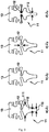
- the figure 3 shows examples of the reference profile to be applied to the characteristic zones defined on the figure 1 .
- FIG. 1a On the figure 1a is shown a graph illustrating the typical variations of the linear force F l applied to a blade of length L by a wiper blade of a wiper of the "Flat blade” technology, when a drive arm of wiper system exerts a pressing force on a central connector of the blade connecting the drive arm to the blade, greater than the force that defined the blade.
- This force of definition of the brush is that for which the distribution of the linear force F l is constant.
- the figure 1b is an equivalent graph in the opposite situation where the drive arm of the wiper system exerts a lower bearing force than the definition force of the wiper.
- the different zones are defined with respect to the horizontal axis corresponding to the value of the linear force F l for which the blade has been calculated. In most cases, this is the average value of the effort under the broom
- the zone Z 1 is the area where the linear force F 1 has the largest value, as a result of the fact that it is the zone located in the immediate vicinity of the central connector on which the support force developed by the drive arm.
- the linear force F l then decreases quite strongly as one moves away from the center of the blade.
- the end of zone Z 1 and the beginning of zone Z 2 which is a zone of relaxation of load where the linear force is weaker until to reach a new point of intersection which can be chosen to mark the boundary between the zone Z 2 and Z 3 area in which the force F takes the intermediate values.
- the linear force F l then decreases sharply from a third intersection defining, for example, the boundary between the zone Z 3 and a zone Z 4 at the end of which the linear force decreases towards zero.
- a database is created grouping the lengths of the characteristic zones and the values of the linear force extracted from a large number of graphs, similar to that of the figure 1 , based either on theoretical models derived from a finite element calculation or other calculation methods, or on actual measurements made on existing wiper blades. In all cases, the wiper blade is assumed to have a profile of constant section.
- the database being thus constituted, one can build the graph of the figure 2 which gives for each of the characteristic zones Z 1 , Z 2 and Z 4 the normalized frequency of a length of zone normalized to the length L of the wiper, between x and x + ⁇ x, x being the variable carried on the abscissa on the figure 2 .
- we count the number of occurrences in the database of a normalized length value between x and x + ⁇ x ( ⁇ x 0.02 for example) for a given characteristic zone, then we divide the number of occurrences thus obtained by the total number of corresponding available data. The result of this calculation is the frequency carried on the ordinate on the figure 2 .
- the length of the zone Z 3 is deduced from those of the other zones in addition to the total length L of the blade.
- zone Z 4 it is possible to choose a fixed length because the short brushes being most often located on the passenger side, it is observed that the variation of curvature of the windshield is greater on the side. passenger only on the driver's side. This first side is thus more difficult to cover. Thus, the area not wiped at the end of the brush tends to increase relative to the total length thereof, hence the interest of defining a constant length for the zone Z 4 .
- zone Z 1 it is necessary to design a very rigid profile accepting large load variations. It is indeed the central area of the "Flat Blade” technology brooms which generally supports the greatest variations of the support force.
- zone Z 2 can be dimensioned so as to operate under lower load conditions. This is sometimes observed in this area through the presence of streaks on either side of the central connector, effectively signaling a lower linear force than elsewhere.
- Zone Z 3 shows intermediate load conditions.
- Zone Z 4 experiences extremely high load variations. In practice, it can be very difficult to fully cover such an area. As, in this zone, it is the sectors of under-pressure which raise the most problems because they are not wiped, it is advantageous to privilege the weak loads, and thus a better follow-up of curve, to realize the dimensioning of zone Z 4 .
- variable stiffness profile can be made in the form of a variable section profile dimensioned to obtain the desired rigidity.
- each zone a reference profile whose section has the desired rigidity, then we connect the different reference profiles by a continuous connection law.
- the reference zones of the zones Z 1 , Z 2 and Z 3 are defined in the center of the respective zone, while for zone Z 4 the reference profile is defined at the end of the brush.
- the wiper blade according to the invention is preferably manufactured by molding an elastomer, this method being particularly well suited to the production of a variable section profile.
- the wiper blade in particular the contact element with the windshield, also called "fir", given its shape generally. triangular, and the hinge which connects the contact element to the heel of the blade, which is engaged in a plastic support which extends along the blade.
- zone Z 1 the linear force varies from 35% to 290% of its nominal force of definition.
- zone Z 2 zone this range varies from 45% to 230%, and from 42% to 240% for the Z 3 zone.
- zone Z 1 which we have seen above that it had to present a more rigid profile and to accept strong variations of the linear force, it is proposed, compared to the basic profile of the figure 3 in c), to widen the shoulders 111 of the tree 11 and to thicken the body 112 and the lip 113, as shown in FIG. figure 3 in a).
- a possible modification is an extension of the hinge 12 with the heel 13, in accordance with the figure 3 in B).
- zone Z 4 the figure 3 d) shows that the body 112 of the fir tree 11 can be narrowed to obtain a profile that accepts light loads and makes it possible to wipe the curved areas of the windshield by virtue of greater flexibility conferred on the blade.
- This hinge reinforcement region can be considered as a fifth zone defined in zone Z 4 .
Landscapes
- Engineering & Computer Science (AREA)
- Mechanical Engineering (AREA)
- Vehicle Cleaning, Maintenance, Repair, Refitting, And Outriggers (AREA)
- Pivots And Pivotal Connections (AREA)
Description
La présente invention concerne une lame d'essuyage de balai d'essuie-glace. Elle concerne également un procédé de réalisation d'une telle lame d'essuyage.The present invention relates to a wiper blade wiper blade. It also relates to a method of producing such a wiper blade.
L'invention trouve une application particulièrement avantageuse dans le domaine des systèmes d'essuyage pour véhicules automobiles, et plus spécialement dans celui des systèmes d'essuyage comprenant des balais d'essuie-glace plats.The invention finds a particularly advantageous application in the field of wiper systems for motor vehicles, and more particularly in that of wiper systems comprising flat windscreen wiper blades.
Actuellement, la majorité des balais d'essuie-glace utilisés sont des balais dits droits, comportant une structure à palonniers (comme par example le balai d'essuie-glace décrit par le document JPS6189152 A).Currently, the majority of wiper blades used are so-called straight brooms, having a spreader structure (such as the wiper blade described in JPS6189152 A).
Ce type de balai d'essuie-glace est peu à peu remplacé par une nouvelle génération de balais dits « plats », connus également sous le terme de « Flat Blade », qui présentent la particularité de ne plus comporter de structure à palonniers (comme par example le balai d'essuie-glace décrit par le document
Un objectif de la technologie de balai plat « Flat blade » est d'obtenir une répartition la plus homogène possible de la force linéique appliquée sur le pare-brise du véhicule, le long de la lame d'essuyage, cette dernière étant soumise en son centre, ou en deux autres points, à une force d'appui exercée par le bras d'entraînement du système d'essuyage sur le connecteur reliant le bras à la lame.One objective of Flat Blade technology is to obtain as homogeneous a distribution as possible of the linear force applied to the windscreen of the vehicle, along the wiper blade, the latter being subjected to center, or in two other points, a pressing force exerted by the drive arm of the wiper system on the connector connecting the arm to the blade.
On entend ici par « force linéique » la force exercée par unité de longueur de lame ; elle s'exprime en N/m.Here "linear force" is understood to mean the force exerted per unit length of blade; it is expressed in N / m.
Cependant, cet objectif n'est pas toujours atteint puisqu'on observe en général que la force linéique sur le pare-brise ne reste pas constante le long de la lame, ceci principalement pour trois raisons :
- le galbe du pare-brise ne correspond pas partout à celui pour lequel a été conçue la tige métallique de rigidification, ou vertèbre, de la structure flexible portant la lame d'essuyage. En effet, le dimensionnement du profil de la tige de rigidification est effectué pour un rayon de courbure moyen du galbe, or un pare-brise peut présenter des variations de galbe importantes. C'est le cas notamment des extrémités de la zone d'essuyage qui souvent ne sont pas couvertes correctement du côté passager, ce qui laisse une surface du pare-brise en situation de manque d'essuyage ;
- pour compenser le soulèvement aérodynamique du bras, un effort supérieur à celui qui serait strictement requis est appliqué sur le balai au niveau du connecteur central de liaison avec le bras. Il en résulte que la lame subit une surpression dans sa partie située sous le connecteur ;
- pour atteindre de bonnes performances aérodynamiques, une tête inclinée liée à l'axe de sortie du moteur d'entraînement du bras est disposée sur le porte-balai, avec pour conséquence une dissymétrie des efforts entre le sens de balayage montant et le sens de balayage descendant. On observe en effet qu'au niveau du connecteur la lame subit une force plus grande dans le sens descendant que dans le sens montant.
- the curve of the windshield does not correspond everywhere to that for which was designed the metal rod stiffening, or vertebra, of the flexible structure carrying the wiper blade. Indeed, the dimensioning of the profile of the stiffening rod is performed for a radius of curvature of the curvature, or a windshield may have significant curve variations. This is particularly the case of the ends of the wiping area which are often not covered correctly on the passenger side, leaving a windshield surface in a situation of lack of wiping;
- to compensate for the aerodynamic lifting of the arm, a force greater than that which would be strictly required is applied to the blade at the central connection connector with the arm. As a result, the blade is overpressured in its part located under the connector;
- to achieve good aerodynamic performance, an inclined head connected to the output axis of the drive motor of the arm is disposed on the brush holder, resulting in an asymmetry of the forces between the upstream scanning direction and the scanning direction descending. It is observed that at the connector the blade undergoes a greater force in the downward direction than in the upward direction.
Ces variations de la force linéique ont pour conséquence un dimensionnement non optimal le long de la lame de grandeurs fonctionnelles, telles que l'angle de calage, l'angle de raclage, etc. Il en résulte une limitation des performances du balai d'essuie-glace en termes par exemple de qualité d'essuyage, d'usure et de bruit.These variations in the linear force result in a non-optimal dimensioning along the blade of functional quantities, such as the wedging angle, the scraping angle, and so on. This results in a limitation of the performance of the wiper blade in terms of, for example, quality of wiping, wear and noise.
Aussi, un but de l'invention est de proposer une lame d'essuyage de balai d'essuie-glace, qui permettrait de prendre en compte les variations de la force linéique le long de la lame de manière à obtenir un dimensionnement optimisé desdites grandeurs fonctionnelles et, ainsi, améliorer les performances du balai.Also, an object of the invention is to provide a wiper blade wiper, which would take into account the variations of the linear force along the blade so as to obtain an optimized dimensioning of said magnitudes functional and thus improve the performance of the broom.
Ce but est atteint, conformément à l'invention, grâce à un balai d'essuie-glace plat selon la revendication 1.This object is achieved, according to the invention, by means of a flat windscreen wiper blade according to
Ainsi, du fait de la prise en compte par le profil de rigidité variable de la lame des variations de la force linéique, on obtient des grandeurs fonctionnelles, angle de calage et angle de raclage notamment, plus homogènes sur le pare-brise permettant d'assurer un meilleur fonctionnement du balai en essuyage, usure, bruit, etc.Thus, because of the fact that the variable stiffness profile of the blade takes into account the variations in the linear force, functional magnitudes, notably the angle of setting and scraping angle, are obtained that are more homogeneous on the windshield, making it possible to ensure better operation of the broom by wiping, wear, noise, etc.
Selon l'invention, ledit profil de rigidité variable est un profil de section variable. En particulier, ladite lame comportant un élément de contact avec ledit pare-brise, relié à un talon par une charnière, ledit profil de section variable concerne des caractéristiques dimensionnelles dudit élément de contact et/ou de ladite charnière et/ou dudit talon.According to the invention, said variable rigidity profile is a variable section profile. In particular, said blade having a contact element with said windshield, connected to a heel by a hinge, said variable section profile concerns dimensional characteristics of said contact element and / or said hinge and / or heel.
L'invention concerne également un procédé de réalisation d'une lame d'essuyage de balai d'essuie-glace tel que défini ci-dessus, remarquable en ce que ledit procédé comprend une étape de détermination d'un profil de rigidité variable consistant à :
- définir une pluralité de zones caractéristiques des variations le long de la lame de la force linéique devant être appliquée par ladite lame sur le pare-brise,
- déterminer une longueur pour chaque zone caractéristique,
- établir dans chaque zone caractéristique une plage de variations de ladite force linéique,
- déterminer, à l'intérieur de chaque zone caractéristique, un profil de référence de la lame, présentant une rigidité compatible au moins partiellement avec ladite plage de variations,
- relier les profils de référence desdites zones caractéristiques selon une loi de raccordement continue.
- defining a plurality of characteristic zones of the variations along the blade of the linear force to be applied by said blade on the windshield,
- determine a length for each characteristic zone,
- establishing in each characteristic zone a range of variations of said linear force,
- determining, within each characteristic zone, a reference profile of the blade having a rigidity compatible at least partially with said range of variations,
- connecting the reference profiles of said characteristic zones according to a continuous connection law.
Selon l'invention, lesdits profils de référence sont des profils définis par des caractéristiques dimensionnelles de la section de la lame. En particulier, ladite lame comportant un élément de contact avec ledit pare-brise, relié à un talon par une charnière, lesdites caractéristiques dimensionnelles concernent ledit élément de contact et/ou ladite charnière et/ou ledit talon.According to the invention, said reference profiles are profiles defined by dimensional characteristics of the section of the blade. In particular, said blade having a contact element with said windshield, connected to a heel by a hinge, said dimensional characteristics concern said contact element and / or said hinge and / or said heel.
Selon un mode de réalisation, ladite loi de raccordement continue est une loi linéaire.According to one embodiment, said continuous connection law is a linear law.
Selon un autre mode de réalisation, ladite loi de raccordement continue est une loi de Timoshenko issue d'un modèle de poutre sur fondation élastique.According to another embodiment, said continuous connection law is a law of Timoshenko resulting from a model of beam on elastic foundation.
La description qui va suivre en regard des dessins annexés, donnés à titre d'exemples non limitatifs, fera bien comprendre en quoi consiste l'invention et comment elle peut être réalisée.The following description with reference to the accompanying drawings, given as non-limiting examples, will make it clear what the invention consists of and how it can be achieved.
La
La
La
La
Sur la
La
Bien entendu, des graphes similaires pourraient être construits dans le cas où la force d'appui serait transmise au balai en deux points d'application ou plus.Of course, similar graphs could be constructed in the case where the support force would be transmitted to the broom at two or more application points.
On voit sur les exemples des
De manière pratique, les différentes zones sont définies par rapport à l'axe horizontal correspondant à la valeur de la force linéique Fl pour laquelle a été calculé le balai. Dans la plupart des cas, il s'agit de la valeur moyenne de l'effort sous le balaiIn practice, the different zones are defined with respect to the horizontal axis corresponding to the value of the linear force F l for which the blade has been calculated. In most cases, this is the average value of the effort under the broom
Concernant le graphe de la
Il en est de même symétriquement pour le graphe de la
On va maintenant déterminer une longueur moyenne pour chaque zone caractéristique. Cette détermination est effectuée de manière statistique, étant entendu qu'une même lame d'essuyage résultant du procédé de dimensionnement que l'on décrit maintenant doit convenir aussi bien à des balais d'essuie-glace de toutes longueurs, qu'à des pare-brises de géométrie différente, ou à des forces d'appui appliquées variables, etc.We will now determine an average length for each characteristic zone. This determination is made statistically, it being understood that the same wiper blade resulting from the sizing process that is now described must be suitable for both windscreen wiper blades of all lengths and for brooms -brises of different geometry, or with varying applied support forces, etc.
Dans ce but, on constitue une base de données regroupant les longueurs des zones caractéristiques et les valeurs de la force linéique extraites d'un grand nombre de graphes, analogue à celui de la
La base de données étant ainsi constituée, on peut construire le graphe de la
On peut ainsi déduire de graphes du type de celui de la
- Z1 varie entre 0,04 L et 0,11 L avec une moyenne de 0,08 L
- Z2 varie entre 0,08 L et 0,24 L avec une moyenne de 0,16 L
- Z4 varie entre 0,04 L et 0,10 L avec une moyenne de 0,07 L ou valeur fixe de 45 mm
- Z 1 varies between 0.04 L and 0.11 L with an average of 0.08 L
- Z 2 varies between 0.08 L and 0.24 L with an average of 0.16 L
- Z 4 varies between 0.04 L and 0.10 L with an average of 0.07 L or a fixed value of 45 mm
La longueur de la zone Z3 se déduit de celles des autres zones par complément à la longueur totale L de la lame.The length of the zone Z 3 is deduced from those of the other zones in addition to the total length L of the blade.
Pour la zone Z4, il est possible de choisir une longueur fixe car les balais de faible longueur étant le plus souvent situés du côté passager, il est observé que la variation de galbe du pare-brise est plus importante du côté passager que du côté conducteur. Ce premier côté est ainsi plus difficile à couvrir. Ainsi, la zone non essuyée en bout de balai a tendance à augmenter par rapport à la longueur totale de celui-ci, d'où l'intérêt de définir une longueur constante pour la zone Z4.For zone Z 4 , it is possible to choose a fixed length because the short brushes being most often located on the passenger side, it is observed that the variation of curvature of the windshield is greater on the side. passenger only on the driver's side. This first side is thus more difficult to cover. Thus, the area not wiped at the end of the brush tends to increase relative to the total length thereof, hence the interest of defining a constant length for the zone Z 4 .
Ensuite, toujours à partir des données statistiques enregistrées dans la base, on peut établir pour chaque zone une plage de variations de la force linéique Fl. Par exemple :
- Z1 : 6 à 50 N/m
- Z2 : 5 à 26 N/m
- Z3 : 6 à 34 N/m
- Z4 : 0 à 50 N/m
- Z 1 : 6 to 50 N / m
- Z 2 : 5 to 26 N / m
- Z 3 : 6 to 34 N / m
- Z 4 : 0 to 50 N / m
On comprend sur ces chiffres qu'il n'est pas possible de concevoir une lame à profil constant qui pourrait accepter l'amplitude totale des variations observées sans risquer de nuire aux autres performances.It is understandable on these figures that it is not possible to design a constant profile blade that could accept the total amplitude of the variations observed without risking to harm the other performances.
Ainsi, pour la zone Z1, il est nécessaire de concevoir un profil très rigide acceptant les fortes variations de charge. C'est en effet la zone centrale des balais de technologie « Flat blade » qui supporte en général les plus grandes variations de la force d'appui.Thus, for zone Z 1 , it is necessary to design a very rigid profile accepting large load variations. It is indeed the central area of the "Flat Blade" technology brooms which generally supports the greatest variations of the support force.
Par contre, la zone Z2 peut être dimensionnée de manière à fonctionner sous des conditions de charge plus faibles. C'est ce qu'on observe parfois dans cette zone à travers la présence de stries de part et d'autre du connecteur central, signalant effectivement une force linéique plus faible qu'ailleurs.On the other hand, zone Z 2 can be dimensioned so as to operate under lower load conditions. This is sometimes observed in this area through the presence of streaks on either side of the central connector, effectively signaling a lower linear force than elsewhere.
La zone Z3 montre des conditions de charge intermédiaires.Zone Z 3 shows intermediate load conditions.
La zone Z4 subit des variations de charge extrêmement élevées. En pratique, il peut être très difficile de couvrir entièrement une telle zone. Comme, dans cette zone, ce sont les secteurs de sous-pression qui soulèvent le plus de problèmes car ils ne sont pas essuyés, il y a avantage à privilégier les faibles charges, et donc un meilleur suivi de galbe, pour réaliser le dimensionnement de la zone Z4.Zone Z 4 experiences extremely high load variations. In practice, it can be very difficult to fully cover such an area. As, in this zone, it is the sectors of under-pressure which raise the most problems because they are not wiped, it is advantageous to privilege the weak loads, and thus a better follow-up of curve, to realize the dimensioning of zone Z 4 .
Il résulte de la discussion qui précède qu'un moyen de concilier les exigences de chaque zone en matière de charge consiste à donner à la lame d'essuyage un profil de rigidité variable en relation avec les variations de la force linéique observées de long de la lame.It follows from the foregoing discussion that a means of reconciling the load requirements of each zone is to provide the wiper blade with a variable stiffness profile in relation to the changes in linear force observed along the length of the load. blade.
Ledit profil de rigidité variable peut être réalisé sous la forme d'un profil de section variable dimensionné pour obtenir la rigidité désirée.Said variable stiffness profile can be made in the form of a variable section profile dimensioned to obtain the desired rigidity.
Concrètement, on définit pour chaque zone, un profil de référence dont la section présente la rigidité recherchée, puis on relie les différents profils de référence par une loi de raccordement continue.Concretely, we define for each zone, a reference profile whose section has the desired rigidity, then we connect the different reference profiles by a continuous connection law.
A titre d'exemple, les zones de référence des zones Z1, Z2, et Z3 sont définies au centre de la zone respective, tandis que pour la zone Z4 le profil de référence est défini en extrémité du balai.By way of example, the reference zones of the zones Z 1 , Z 2 and Z 3 are defined in the center of the respective zone, while for zone Z 4 the reference profile is defined at the end of the brush.
La loi de raccordement continue peut être une loi linéaire. Mais on peut choisir aussi une loi de variation du profil en accord avec la variation de la force linéique du balai, ceci pour une meilleure adéquation entre la géométrie du profil et la répartition de la force sous le balai. Une telle loi de variation est issue par exemple du modèle de poutre sur une fondation élastique de Timoshenko. Cette loi est de la forme f(x) = A.e-kx.(cos(k.x) + sin(k.x)).The law of continuous connection can be a linear law. But one can also choose a law of variation of the profile in agreement with the variation of the linear force of the brush, this for a better adequation between the geometry of the profile and the distribution of the force under the brush. Such a law of variation is issued for example from the beam model on an elastic foundation of Timoshenko. This law is of the form f (x) = Ae -kx (cos (kx) + sin (kx)).
La lame d'essuyage conforme à l'invention est fabriquée de préférence par moulage d'un élastomère, ce procédé étant particulièrement bien adapté à la réalisation d'un profil à section variable.The wiper blade according to the invention is preferably manufactured by molding an elastomer, this method being particularly well suited to the production of a variable section profile.
Pour obtenir un profil de section variable présentant une rigidité donnée, on peut agir sur les caractéristiques dimensionnelles de la lame d'essuyage, en particulier l'élément de contact avec le pare-brise, appelé aussi « sapin » compte tenu de sa forme généralement triangulaire, et la charnière qui relie l'élément de contact au talon de la lame, lequel est engagé dans un support plastique qui s'étend le long de la lame.To obtain a variable section profile having a given rigidity, it is possible to act on the dimensional characteristics of the wiper blade, in particular the contact element with the windshield, also called "fir", given its shape generally. triangular, and the hinge which connects the contact element to the heel of the blade, which is engaged in a plastic support which extends along the blade.
On va maintenant montrer sur un exemple comment ces caractéristiques dimensionnelles peuvent être modifiées.We will now show on an example how these dimensional characteristics can be modified.
En reprenant les plages de variations de la force linéique pour les différentes zones caractéristiques Z1, Z2 et Z3 précédemment définies, et en appliquant pour ces zones les forces linéiques nominales de définition généralement observées de 17,2, 11,2 et 14,2 N/m respectivement, on constate que pour la zone Z1, la force linéique varie de 35% à 290% de sa force nominale de définition. Pour la zone Z2, cet intervalle varie de 45% à 230%, et de 42% à 240% pour la zone Z3.By taking again the ranges of variations of the linear force for the different characteristic zones Z 1 , Z 2 and Z 3 previously defined, and by applying for these zones the generally observed nominal linear strengths of definition of 17,2, 11,2 and 14 , 2 N / m respectively, one notes that for zone Z 1 , the linear force varies from 35% to 290% of its nominal force of definition. For the Z 2 zone, this range varies from 45% to 230%, and from 42% to 240% for the Z 3 zone.
Actuellement, les profils courants en production acceptent en général des variations de 42% à 240% de la force nominale de définition. Ce type de profil standard peut donc être appliqué à la zone Z3 sans modification pour constituer le profil de référence de cette zone. On peut également utiliser ce même profil comme base à partir de laquelle les caractéristiques dimensionnelles de l'élément de contact et de la charnière doivent être modifiées afin d'obtenir le profil de référence des autres zones. C'est ce que montre la
Pour la zone Z1 dont on a vu plus haut qu'elle devait présenter un profil plus rigide et accepter de fortes variations de la force linéique, il est proposé, par rapport au profil de base de la
Pour la zone Z2 qui peut accepter des charges plus faibles, une modification possible est un allongement de la charnière 12 avec le talon 13, conformément à la
Enfin, pour la zone Z4, la
Il est également possible d'agir sur les caractéristiques du talon 13 pour obtenir la rigidité souhaitée.It is also possible to act on the characteristics of the
On observera que le profil n'étant pas dimensionné de manière uniforme sur toute la longueur de la lame, des contraintes peuvent être libérées, ce qui permet d'avoir plus de degrés de liberté pour la conception du profil par rapport à d'autres contraintes, comme le bruit par exemple.It will be observed that since the profile is not dimensioned uniformly over the entire length of the blade, stresses can be released, which makes it possible to have more degrees of freedom for the design of the profile compared to other constraints. like noise for example.
Claims (8)
- Flat wiper blade comprising a central connector and a flexible structure comprising a metal rigidification rod and bearing a wiping blade, said blade being intended to be submitted to a bearing force against a windscreen of a vehicle, characterised in that said blade has a variable rigidity profile comprising a plurality of characteristic areas (Z1, Z2, Z3, Z4), said variable rigidity profile being in relation with the variations along the blade of the lineic force (FI) which must be applied by the blade on said windscreen, one area (Z1) being the one where the lineic force (FI) has the greatest value, said area (Z1) being located in the close vicinity of the central connector on which a bearing force developed by a driving arm can be exerted.
- Flat wiper blade according to claim 1, wherein said variable rigidity profile is a variable section profile.
- Flat wiper blade, according to claim 2, wherein, said blade comprising one element (11) of contact with said windscreen, connected to a foot (13) by a hinge (12), said variable section profile relates to dimensional characteristics of said contact element (11) and/or of said hinge (12) and/or of said foot (13).
- Method for making a wiping blade for a wiper blade as defined in any of the preceding claims, characterised in that said method comprises one step of determining a variable rigidity profile consisting in:- defining a plurality of characteristic areas (Z1, Z2, Z3, Z4) of variations along the blade of the lineic force (FI) to be applied by said blade against said windscreen, one area (Z1) being the one where the lineic force (FI) has the greatest value, said area (Z1) being located in the close vicinity of the central connector on which a bearing force developed by a driving arm can be exerted,- determining a length for each characteristic area,- establishing in each characteristic area a variation range of the lineic force (FI),- determining within each characteristic area, a reference profile of the blade having a rigidity at least partially compatible with said variation range,- connecting the reference profiles of said characteristic areas (Z1, Z2, Z3, Z4) according to a continuous connection rule.
- A method according to claim 4, wherein said reference profiles are profiles defined by dimensional characteristics of the section of the blade.
- A method according to claim 5, wherein, said blade comprising an element (11) of contact with said windscreen, connected to a foot (13) by a hinge (12), said dimensional characteristics relating to said contact element (11) and/or of said hinge (12) and/or of said foot (13).
- A method according to any one of claims 4 to 6, wherein said continuous connection rule is a linear rule.
- A method according to any one of claims 4 to 6, wherein said continuous connection rule is Timoshenko's rule resulting from a model of beam on an elastic foundation.
Applications Claiming Priority (2)
| Application Number | Priority Date | Filing Date | Title |
|---|---|---|---|
| FR0800260A FR2926513B1 (en) | 2008-01-18 | 2008-01-18 | WIPER BLADE OF A WIPER BLADE AND METHOD OF MAKING SAME |
| PCT/EP2009/050484 WO2009092667A1 (en) | 2008-01-18 | 2009-01-16 | Wiping blade for wiper and method for making same |
Publications (2)
| Publication Number | Publication Date |
|---|---|
| EP2242670A1 EP2242670A1 (en) | 2010-10-27 |
| EP2242670B1 true EP2242670B1 (en) | 2018-10-17 |
Family
ID=39661395
Family Applications (1)
| Application Number | Title | Priority Date | Filing Date |
|---|---|---|---|
| EP09703851.7A Revoked EP2242670B1 (en) | 2008-01-18 | 2009-01-16 | Wiping blade for wiper and method for making same |
Country Status (4)
| Country | Link |
|---|---|
| EP (1) | EP2242670B1 (en) |
| JP (1) | JP5889532B2 (en) |
| FR (1) | FR2926513B1 (en) |
| WO (1) | WO2009092667A1 (en) |
Citations (2)
| Publication number | Priority date | Publication date | Assignee | Title |
|---|---|---|---|---|
| US3192551A (en) * | 1964-08-31 | 1965-07-06 | Walter D Appel | Windshield wiper blade assembly |
| JPS6189152A (en) * | 1984-10-08 | 1986-05-07 | Nippon Denso Co Ltd | Wiper blade rubber |
Family Cites Families (5)
| Publication number | Priority date | Publication date | Assignee | Title |
|---|---|---|---|---|
| JPH0678054B2 (en) * | 1984-04-24 | 1994-10-05 | 自動車電機工業株式会社 | Wiper blade |
| JPH0710661B2 (en) * | 1992-03-13 | 1995-02-08 | 自動車電機工業株式会社 | Wiper blade |
| JP2546976B2 (en) * | 1994-06-17 | 1996-10-23 | 自動車電機工業株式会社 | Wiper blade |
| JPH08268236A (en) * | 1995-03-31 | 1996-10-15 | Asmo Co Ltd | Wiper blade rubber |
| WO2000021809A1 (en) * | 1998-10-09 | 2000-04-20 | Trico Products Corporation | A windscreen wiper |
-
2008
- 2008-01-18 FR FR0800260A patent/FR2926513B1/en active Active
-
2009
- 2009-01-16 EP EP09703851.7A patent/EP2242670B1/en not_active Revoked
- 2009-01-16 JP JP2010542636A patent/JP5889532B2/en active Active
- 2009-01-16 WO PCT/EP2009/050484 patent/WO2009092667A1/en active Application Filing
Patent Citations (2)
| Publication number | Priority date | Publication date | Assignee | Title |
|---|---|---|---|---|
| US3192551A (en) * | 1964-08-31 | 1965-07-06 | Walter D Appel | Windshield wiper blade assembly |
| JPS6189152A (en) * | 1984-10-08 | 1986-05-07 | Nippon Denso Co Ltd | Wiper blade rubber |
Also Published As
| Publication number | Publication date |
|---|---|
| WO2009092667A1 (en) | 2009-07-30 |
| JP2011509866A (en) | 2011-03-31 |
| JP5889532B2 (en) | 2016-03-22 |
| EP2242670A1 (en) | 2010-10-27 |
| FR2926513B1 (en) | 2010-06-11 |
| FR2926513A1 (en) | 2009-07-24 |
Similar Documents
| Publication | Publication Date | Title |
|---|---|---|
| FR2935296A1 (en) | TIRE TREAD WITH DIRECTIONAL SCULPTURE. | |
| EP3168092B1 (en) | Element for a system for connecting a windscreen wiper blade holder to a drive arm | |
| EP2242670B1 (en) | Wiping blade for wiper and method for making same | |
| FR3013013A1 (en) | WIPER DEVICE | |
| EP2209677B1 (en) | Windscreen wiper arm | |
| EP3368338B1 (en) | Pneumatic tire, having working layers comprising monofilaments and a tire tread with grooves | |
| FR2862559A1 (en) | Motor vehicle axle suspension arm manufacturing procedure has articulated joints overmolded in polymer onto ends of rigid bar | |
| EP3621824B1 (en) | Tyre with optimised crown and tread | |
| EP3368349B1 (en) | Pneumatic tire, having working layers comprising monofilaments and a tire tread with incisions | |
| FR2988357A1 (en) | WIPING BLADE WITH REDUCED FRICTION COEFFICIENT | |
| FR2914600A1 (en) | STOPPER FOR THE PROTECTION OF A FIRST ELEMENT AT THE MEETING WITH A SECOND ELEMENT. | |
| FR3056951B1 (en) | SUPPORT FRAME FOR WIPER BLADE, WIPER BLADE AND WIPING SYSTEM THEREFOR | |
| FR2929882A1 (en) | RADIUS FOR A SPOKE WHEEL, WHEEL AND CORRESPONDING METHOD | |
| FR2793437A1 (en) | INJECTION RUBBER MOLDING NOZZLE, INJECTION MOLDING MACHINE AND MOLDING METHOD | |
| FR3010370A1 (en) | FILM-HINGE OF WIPER DEVICE | |
| EP3898279A1 (en) | Tread comprising hidden cavities and grooves | |
| EP2247475B1 (en) | Method for making a washing liquid dispensing line, wiper blade and wiping device provided with a dispensing line obtained from said method | |
| FR3010369A1 (en) | VEHICLE ICE WIPER DEVICE, MANUFACTURING METHOD THEREFOR, AND CONSTRUCTION BOX FOR MANUFACTURING ICE WIPER DEVICE | |
| EP4071001B1 (en) | Foam schock absorber for automobile vehicle | |
| FR3013015A1 (en) | WIPER DEVICE | |
| FR3024103A1 (en) | WINDSHIELD WIPER STRENGTH VARIATION WIPER DEVICE FIN-RAY | |
| FR3010372A1 (en) | IAM WIPER DEVICE HAVING A RADIANT STRUCTURE | |
| EP3621825B1 (en) | Tyre with optimised architecture and tread | |
| WO2023160927A1 (en) | Wiper blade | |
| WO2024061906A1 (en) | Supporting device for windshield wiper mechanism |
Legal Events
| Date | Code | Title | Description |
|---|---|---|---|
| PUAI | Public reference made under article 153(3) epc to a published international application that has entered the european phase |
Free format text: ORIGINAL CODE: 0009012 |
|
| 17P | Request for examination filed |
Effective date: 20100719 |
|
| AK | Designated contracting states |
Kind code of ref document: A1 Designated state(s): AT BE BG CH CY CZ DE DK EE ES FI FR GB GR HR HU IE IS IT LI LT LU LV MC MK MT NL NO PL PT RO SE SI SK TR |
|
| AX | Request for extension of the european patent |
Extension state: AL BA RS |
|
| DAX | Request for extension of the european patent (deleted) | ||
| 17Q | First examination report despatched |
Effective date: 20120720 |
|
| STAA | Information on the status of an ep patent application or granted ep patent |
Free format text: STATUS: EXAMINATION IS IN PROGRESS |
|
| GRAP | Despatch of communication of intention to grant a patent |
Free format text: ORIGINAL CODE: EPIDOSNIGR1 |
|
| STAA | Information on the status of an ep patent application or granted ep patent |
Free format text: STATUS: GRANT OF PATENT IS INTENDED |
|
| INTG | Intention to grant announced |
Effective date: 20180518 |
|
| RIN1 | Information on inventor provided before grant (corrected) |
Inventor name: PETITET, GILLES |
|
| GRAS | Grant fee paid |
Free format text: ORIGINAL CODE: EPIDOSNIGR3 |
|
| GRAA | (expected) grant |
Free format text: ORIGINAL CODE: 0009210 |
|
| STAA | Information on the status of an ep patent application or granted ep patent |
Free format text: STATUS: THE PATENT HAS BEEN GRANTED |
|
| AK | Designated contracting states |
Kind code of ref document: B1 Designated state(s): AT BE BG CH CY CZ DE DK EE ES FI FR GB GR HR HU IE IS IT LI LT LU LV MC MK MT NL NO PL PT RO SE SI SK TR |
|
| REG | Reference to a national code |
Ref country code: GB Ref legal event code: FG4D Free format text: NOT ENGLISH |
|
| REG | Reference to a national code |
Ref country code: CH Ref legal event code: EP |
|
| REG | Reference to a national code |
Ref country code: IE Ref legal event code: FG4D Free format text: LANGUAGE OF EP DOCUMENT: FRENCH |
|
| REG | Reference to a national code |
Ref country code: AT Ref legal event code: REF Ref document number: 1053612 Country of ref document: AT Kind code of ref document: T Effective date: 20181115 Ref country code: DE Ref legal event code: R096 Ref document number: 602009055089 Country of ref document: DE |
|
| REG | Reference to a national code |
Ref country code: NL Ref legal event code: MP Effective date: 20181017 |
|
| REG | Reference to a national code |
Ref country code: LT Ref legal event code: MG4D |
|
| REG | Reference to a national code |
Ref country code: AT Ref legal event code: MK05 Ref document number: 1053612 Country of ref document: AT Kind code of ref document: T Effective date: 20181017 |
|
| PG25 | Lapsed in a contracting state [announced via postgrant information from national office to epo] |
Ref country code: NL Free format text: LAPSE BECAUSE OF FAILURE TO SUBMIT A TRANSLATION OF THE DESCRIPTION OR TO PAY THE FEE WITHIN THE PRESCRIBED TIME-LIMIT Effective date: 20181017 |
|
| PG25 | Lapsed in a contracting state [announced via postgrant information from national office to epo] |
Ref country code: HR Free format text: LAPSE BECAUSE OF FAILURE TO SUBMIT A TRANSLATION OF THE DESCRIPTION OR TO PAY THE FEE WITHIN THE PRESCRIBED TIME-LIMIT Effective date: 20181017 Ref country code: BG Free format text: LAPSE BECAUSE OF FAILURE TO SUBMIT A TRANSLATION OF THE DESCRIPTION OR TO PAY THE FEE WITHIN THE PRESCRIBED TIME-LIMIT Effective date: 20190117 Ref country code: PL Free format text: LAPSE BECAUSE OF FAILURE TO SUBMIT A TRANSLATION OF THE DESCRIPTION OR TO PAY THE FEE WITHIN THE PRESCRIBED TIME-LIMIT Effective date: 20181017 Ref country code: LT Free format text: LAPSE BECAUSE OF FAILURE TO SUBMIT A TRANSLATION OF THE DESCRIPTION OR TO PAY THE FEE WITHIN THE PRESCRIBED TIME-LIMIT Effective date: 20181017 Ref country code: LV Free format text: LAPSE BECAUSE OF FAILURE TO SUBMIT A TRANSLATION OF THE DESCRIPTION OR TO PAY THE FEE WITHIN THE PRESCRIBED TIME-LIMIT Effective date: 20181017 Ref country code: ES Free format text: LAPSE BECAUSE OF FAILURE TO SUBMIT A TRANSLATION OF THE DESCRIPTION OR TO PAY THE FEE WITHIN THE PRESCRIBED TIME-LIMIT Effective date: 20181017 Ref country code: AT Free format text: LAPSE BECAUSE OF FAILURE TO SUBMIT A TRANSLATION OF THE DESCRIPTION OR TO PAY THE FEE WITHIN THE PRESCRIBED TIME-LIMIT Effective date: 20181017 Ref country code: NO Free format text: LAPSE BECAUSE OF FAILURE TO SUBMIT A TRANSLATION OF THE DESCRIPTION OR TO PAY THE FEE WITHIN THE PRESCRIBED TIME-LIMIT Effective date: 20190117 Ref country code: FI Free format text: LAPSE BECAUSE OF FAILURE TO SUBMIT A TRANSLATION OF THE DESCRIPTION OR TO PAY THE FEE WITHIN THE PRESCRIBED TIME-LIMIT Effective date: 20181017 Ref country code: IS Free format text: LAPSE BECAUSE OF FAILURE TO SUBMIT A TRANSLATION OF THE DESCRIPTION OR TO PAY THE FEE WITHIN THE PRESCRIBED TIME-LIMIT Effective date: 20190217 |
|
| PG25 | Lapsed in a contracting state [announced via postgrant information from national office to epo] |
Ref country code: SE Free format text: LAPSE BECAUSE OF FAILURE TO SUBMIT A TRANSLATION OF THE DESCRIPTION OR TO PAY THE FEE WITHIN THE PRESCRIBED TIME-LIMIT Effective date: 20181017 Ref country code: GR Free format text: LAPSE BECAUSE OF FAILURE TO SUBMIT A TRANSLATION OF THE DESCRIPTION OR TO PAY THE FEE WITHIN THE PRESCRIBED TIME-LIMIT Effective date: 20190118 Ref country code: PT Free format text: LAPSE BECAUSE OF FAILURE TO SUBMIT A TRANSLATION OF THE DESCRIPTION OR TO PAY THE FEE WITHIN THE PRESCRIBED TIME-LIMIT Effective date: 20190217 |
|
| REG | Reference to a national code |
Ref country code: DE Ref legal event code: R026 Ref document number: 602009055089 Country of ref document: DE |
|
| PLBI | Opposition filed |
Free format text: ORIGINAL CODE: 0009260 |
|
| PLAX | Notice of opposition and request to file observation + time limit sent |
Free format text: ORIGINAL CODE: EPIDOSNOBS2 |
|
| PG25 | Lapsed in a contracting state [announced via postgrant information from national office to epo] |
Ref country code: IT Free format text: LAPSE BECAUSE OF FAILURE TO SUBMIT A TRANSLATION OF THE DESCRIPTION OR TO PAY THE FEE WITHIN THE PRESCRIBED TIME-LIMIT Effective date: 20181017 Ref country code: DK Free format text: LAPSE BECAUSE OF FAILURE TO SUBMIT A TRANSLATION OF THE DESCRIPTION OR TO PAY THE FEE WITHIN THE PRESCRIBED TIME-LIMIT Effective date: 20181017 Ref country code: CZ Free format text: LAPSE BECAUSE OF FAILURE TO SUBMIT A TRANSLATION OF THE DESCRIPTION OR TO PAY THE FEE WITHIN THE PRESCRIBED TIME-LIMIT Effective date: 20181017 |
|
| 26 | Opposition filed |
Opponent name: TRICO BELGIUM S.A. Effective date: 20190717 |
|
| PG25 | Lapsed in a contracting state [announced via postgrant information from national office to epo] |
Ref country code: MC Free format text: LAPSE BECAUSE OF FAILURE TO SUBMIT A TRANSLATION OF THE DESCRIPTION OR TO PAY THE FEE WITHIN THE PRESCRIBED TIME-LIMIT Effective date: 20181017 Ref country code: RO Free format text: LAPSE BECAUSE OF FAILURE TO SUBMIT A TRANSLATION OF THE DESCRIPTION OR TO PAY THE FEE WITHIN THE PRESCRIBED TIME-LIMIT Effective date: 20181017 Ref country code: SK Free format text: LAPSE BECAUSE OF FAILURE TO SUBMIT A TRANSLATION OF THE DESCRIPTION OR TO PAY THE FEE WITHIN THE PRESCRIBED TIME-LIMIT Effective date: 20181017 Ref country code: EE Free format text: LAPSE BECAUSE OF FAILURE TO SUBMIT A TRANSLATION OF THE DESCRIPTION OR TO PAY THE FEE WITHIN THE PRESCRIBED TIME-LIMIT Effective date: 20181017 |
|
| REG | Reference to a national code |
Ref country code: CH Ref legal event code: PL |
|
| PG25 | Lapsed in a contracting state [announced via postgrant information from national office to epo] |
Ref country code: LU Free format text: LAPSE BECAUSE OF NON-PAYMENT OF DUE FEES Effective date: 20190116 |
|
| REG | Reference to a national code |
Ref country code: IE Ref legal event code: MM4A |
|
| PG25 | Lapsed in a contracting state [announced via postgrant information from national office to epo] |
Ref country code: SI Free format text: LAPSE BECAUSE OF FAILURE TO SUBMIT A TRANSLATION OF THE DESCRIPTION OR TO PAY THE FEE WITHIN THE PRESCRIBED TIME-LIMIT Effective date: 20181017 |
|
| PLBB | Reply of patent proprietor to notice(s) of opposition received |
Free format text: ORIGINAL CODE: EPIDOSNOBS3 |
|
| PG25 | Lapsed in a contracting state [announced via postgrant information from national office to epo] |
Ref country code: CH Free format text: LAPSE BECAUSE OF NON-PAYMENT OF DUE FEES Effective date: 20190131 Ref country code: LI Free format text: LAPSE BECAUSE OF NON-PAYMENT OF DUE FEES Effective date: 20190131 |
|
| PG25 | Lapsed in a contracting state [announced via postgrant information from national office to epo] |
Ref country code: IE Free format text: LAPSE BECAUSE OF NON-PAYMENT OF DUE FEES Effective date: 20190116 |
|
| PGFP | Annual fee paid to national office [announced via postgrant information from national office to epo] |
Ref country code: GB Payment date: 20200131 Year of fee payment: 12 |
|
| PG25 | Lapsed in a contracting state [announced via postgrant information from national office to epo] |
Ref country code: MT Free format text: LAPSE BECAUSE OF FAILURE TO SUBMIT A TRANSLATION OF THE DESCRIPTION OR TO PAY THE FEE WITHIN THE PRESCRIBED TIME-LIMIT Effective date: 20181017 |
|
| PGFP | Annual fee paid to national office [announced via postgrant information from national office to epo] |
Ref country code: TR Payment date: 20200106 Year of fee payment: 12 |
|
| REG | Reference to a national code |
Ref country code: DE Ref legal event code: R103 Ref document number: 602009055089 Country of ref document: DE Ref country code: DE Ref legal event code: R064 Ref document number: 602009055089 Country of ref document: DE |
|
| PGFP | Annual fee paid to national office [announced via postgrant information from national office to epo] |
Ref country code: FR Payment date: 20210128 Year of fee payment: 13 |
|
| RDAF | Communication despatched that patent is revoked |
Free format text: ORIGINAL CODE: EPIDOSNREV1 |
|
| PG25 | Lapsed in a contracting state [announced via postgrant information from national office to epo] |
Ref country code: CY Free format text: LAPSE BECAUSE OF FAILURE TO SUBMIT A TRANSLATION OF THE DESCRIPTION OR TO PAY THE FEE WITHIN THE PRESCRIBED TIME-LIMIT Effective date: 20181017 |
|
| PGFP | Annual fee paid to national office [announced via postgrant information from national office to epo] |
Ref country code: DE Payment date: 20210112 Year of fee payment: 13 Ref country code: BE Payment date: 20210114 Year of fee payment: 13 |
|
| PG25 | Lapsed in a contracting state [announced via postgrant information from national office to epo] |
Ref country code: HU Free format text: LAPSE BECAUSE OF FAILURE TO SUBMIT A TRANSLATION OF THE DESCRIPTION OR TO PAY THE FEE WITHIN THE PRESCRIBED TIME-LIMIT; INVALID AB INITIO Effective date: 20090116 |
|
| RDAG | Patent revoked |
Free format text: ORIGINAL CODE: 0009271 |
|
| STAA | Information on the status of an ep patent application or granted ep patent |
Free format text: STATUS: PATENT REVOKED |
|
| REG | Reference to a national code |
Ref country code: CH Ref legal event code: PL |
|
| REG | Reference to a national code |
Ref country code: FI Ref legal event code: MGE |
|
| 27W | Patent revoked |
Effective date: 20210421 |
|
| GBPR | Gb: patent revoked under art. 102 of the ep convention designating the uk as contracting state |
Effective date: 20210421 |
|
| PG25 | Lapsed in a contracting state [announced via postgrant information from national office to epo] |
Ref country code: MK Free format text: LAPSE BECAUSE OF FAILURE TO SUBMIT A TRANSLATION OF THE DESCRIPTION OR TO PAY THE FEE WITHIN THE PRESCRIBED TIME-LIMIT Effective date: 20181017 |