EP2242159A2 - Windpark, Verfahren zum Korrigieren von Spannungsschwankungen und Windturbine - Google Patents
Windpark, Verfahren zum Korrigieren von Spannungsschwankungen und Windturbine Download PDFInfo
- Publication number
- EP2242159A2 EP2242159A2 EP10160003A EP10160003A EP2242159A2 EP 2242159 A2 EP2242159 A2 EP 2242159A2 EP 10160003 A EP10160003 A EP 10160003A EP 10160003 A EP10160003 A EP 10160003A EP 2242159 A2 EP2242159 A2 EP 2242159A2
- Authority
- EP
- European Patent Office
- Prior art keywords
- tap changer
- power grid
- tap
- transformer
- coupled
- Prior art date
- Legal status (The legal status is an assumption and is not a legal conclusion. Google has not performed a legal analysis and makes no representation as to the accuracy of the status listed.)
- Granted
Links
Images


Classifications
-
- H—ELECTRICITY
- H02—GENERATION; CONVERSION OR DISTRIBUTION OF ELECTRIC POWER
- H02J—ELECTRIC POWER NETWORKS; CIRCUIT ARRANGEMENTS OR SYSTEMS FOR SUPPLYING OR DISTRIBUTING ELECTRIC POWER; SYSTEMS FOR STORING ELECTRIC ENERGY
- H02J3/00—Circuit arrangements for AC mains or AC distribution networks
- H02J3/26—Arrangements for eliminating or reducing asymmetry in polyphase networks
-
- H—ELECTRICITY
- H02—GENERATION; CONVERSION OR DISTRIBUTION OF ELECTRIC POWER
- H02J—ELECTRIC POWER NETWORKS; CIRCUIT ARRANGEMENTS OR SYSTEMS FOR SUPPLYING OR DISTRIBUTING ELECTRIC POWER; SYSTEMS FOR STORING ELECTRIC ENERGY
- H02J3/00—Circuit arrangements for AC mains or AC distribution networks
- H02J3/18—Arrangements for adjusting, eliminating or compensating reactive power in networks
- H02J3/1878—Arrangements for adjusting, eliminating or compensating reactive power in networks using tap changing or phase shifting transformers
-
- H—ELECTRICITY
- H02—GENERATION; CONVERSION OR DISTRIBUTION OF ELECTRIC POWER
- H02J—ELECTRIC POWER NETWORKS; CIRCUIT ARRANGEMENTS OR SYSTEMS FOR SUPPLYING OR DISTRIBUTING ELECTRIC POWER; SYSTEMS FOR STORING ELECTRIC ENERGY
- H02J2101/00—Supply or distribution of decentralised, dispersed or local electric power generation
- H02J2101/20—Dispersed power generation using renewable energy sources
- H02J2101/28—Wind energy
-
- H—ELECTRICITY
- H02—GENERATION; CONVERSION OR DISTRIBUTION OF ELECTRIC POWER
- H02J—ELECTRIC POWER NETWORKS; CIRCUIT ARRANGEMENTS OR SYSTEMS FOR SUPPLYING OR DISTRIBUTING ELECTRIC POWER; SYSTEMS FOR STORING ELECTRIC ENERGY
- H02J3/00—Circuit arrangements for AC mains or AC distribution networks
- H02J3/38—Arrangements for feeding a single network from two or more generators or sources in parallel; Arrangements for feeding already energised networks from additional generators or sources in parallel
- H02J3/381—Dispersed generators
-
- Y—GENERAL TAGGING OF NEW TECHNOLOGICAL DEVELOPMENTS; GENERAL TAGGING OF CROSS-SECTIONAL TECHNOLOGIES SPANNING OVER SEVERAL SECTIONS OF THE IPC; TECHNICAL SUBJECTS COVERED BY FORMER USPC CROSS-REFERENCE ART COLLECTIONS [XRACs] AND DIGESTS
- Y02—TECHNOLOGIES OR APPLICATIONS FOR MITIGATION OR ADAPTATION AGAINST CLIMATE CHANGE
- Y02E—REDUCTION OF GREENHOUSE GAS [GHG] EMISSIONS, RELATED TO ENERGY GENERATION, TRANSMISSION OR DISTRIBUTION
- Y02E10/00—Energy generation through renewable energy sources
- Y02E10/70—Wind energy
- Y02E10/76—Power conversion electric or electronic aspects
-
- Y—GENERAL TAGGING OF NEW TECHNOLOGICAL DEVELOPMENTS; GENERAL TAGGING OF CROSS-SECTIONAL TECHNOLOGIES SPANNING OVER SEVERAL SECTIONS OF THE IPC; TECHNICAL SUBJECTS COVERED BY FORMER USPC CROSS-REFERENCE ART COLLECTIONS [XRACs] AND DIGESTS
- Y02—TECHNOLOGIES OR APPLICATIONS FOR MITIGATION OR ADAPTATION AGAINST CLIMATE CHANGE
- Y02E—REDUCTION OF GREENHOUSE GAS [GHG] EMISSIONS, RELATED TO ENERGY GENERATION, TRANSMISSION OR DISTRIBUTION
- Y02E40/00—Technologies for an efficient electrical power generation, transmission or distribution
- Y02E40/30—Reactive power compensation
-
- Y—GENERAL TAGGING OF NEW TECHNOLOGICAL DEVELOPMENTS; GENERAL TAGGING OF CROSS-SECTIONAL TECHNOLOGIES SPANNING OVER SEVERAL SECTIONS OF THE IPC; TECHNICAL SUBJECTS COVERED BY FORMER USPC CROSS-REFERENCE ART COLLECTIONS [XRACs] AND DIGESTS
- Y02—TECHNOLOGIES OR APPLICATIONS FOR MITIGATION OR ADAPTATION AGAINST CLIMATE CHANGE
- Y02E—REDUCTION OF GREENHOUSE GAS [GHG] EMISSIONS, RELATED TO ENERGY GENERATION, TRANSMISSION OR DISTRIBUTION
- Y02E40/00—Technologies for an efficient electrical power generation, transmission or distribution
- Y02E40/50—Arrangements for eliminating or reducing asymmetry in polyphase networks
Definitions
- the present invention relates generally to a wind park and a method of correcting voltage imbalances. Further, the present invention relates to a wind turbine.
- Wind parks usually comprise a plurality of wind turbines which are coupled via a main transformer to a power grid. Voltage imbalances may occur on the power grid. These voltage imbalances may be coupled into the wind park via the main transformer.
- An unbalanced supply voltage from the power grid will typically give rise to a dc (direct current) link voltage variation at twice the line frequency in a grid-connected converter of the wind turbine.
- This dc voltage variation may result in an asymmetrical current with high total harmonics distortion (THD) if no voltage imbalance correction is implemented.
- Grid code requirements may not be fulfilled if an asymmetrical current with high THD is injected to the grid. Therefore, the grid code requirements may not be fulfilled due to the presence of voltage imbalances.
- one objective of the present invention is to avoid the above-mentioned problems.
- a wind park including: at least one wind turbine; a transformer coupled between the at least one wind turbine and a power grid, wherein the transformer includes a primary winding arrangement coupled to the power grid, and a secondary winding arrangement coupled to the at least one wind turbine.
- the power grid includes at least three power lines, each power line conducting a respective phase of a multi-phase current, wherein each power line of the power grid is coupled to the primary winding arrangement via an individual tap changer.
- the primary winding arrangement includes at least three windings.
- the primary winding arrangement has three windings.
- each winding of the primary winding arrangement is coupled to a respective power line of the power grid via an individual tap changer.
- each tap changer includes a plurality of contact points or a continuous contact line being connected to the primary winding arrangement.
- the primary winding arrangement can be connectable to the power lines via the contact points or the contact line.
- each tap changer further includes a sliding contact for selectively contacting one of the plurality of contact points or for sliding along the contact line.
- each tap changer further includes a switch assigned to each contact point.
- Each switch can connect one contact point to the power lines.
- the tap changer is one or more of a group consisting of a mechanical tap changer, an electrical tap changer, and an electrical assisted tap changer.
- the secondary winding arrangement includes a plurality of windings.
- the primary winding arrangement and the secondary winding arrangement have the same number of windings.
- the windings of the secondary winding arrangement are connected in a wye configuration or a delta configuration.
- the wind park further includes a detection unit coupled to the power grid.
- the detection unit can be configured to detect voltage imbalances occurring on the power grid coupled to the primary winding arrangement.
- the wind park further includes a processing unit coupled to the detection unit.
- the processing unit can be configured to calculate respective tap changer adjustments for each tap changer needed in order to compensate influences of the detected voltage imbalances on the wind turbines.
- the transformer serves as a centralized transformer for a plurality of wind turbines.
- the transformer is implemented within the at least one wind turbine.
- a method of correcting voltage imbalances occurring on a power grid being coupled to a wind park via a transformer, the transformer having one or more tap changers includes detecting voltage imbalances occurring on the power grid; calculating respective tap changer adjustments for the at least one tap changer needed in order to compensate influences of the detected voltage imbalances on the wind turbines; and adjusting the at least one tap changer based on the respective calculated tap changer adjustments.
- a first set of tap changers may be adjusted based on one calculated tap changer adjustment and a second set of tap changers may be adjusted based on a further calculated tap changer adjustment.
- the adjusting of the at least one tap changer includes changing or adjusting electrical connections between the power grid and a plurality of contact points or a continuous contact line being connected to the primary winding arrangement of the transformer.
- the changing or adjusting of electrical connections between the power grid and the contact points includes selectively contacting one of the plurality of contact points.
- the changing or adjusting of electrical connections between the power grid and the contact line includes moving a sliding contact along the contact line.
- the changing or adjusting of electrical connections between the power grid and the contact points or the contact line includes opening or closing a switch of each contact point.
- Figure 1 illustrates a common setup of a conventional wind turbine.
- Figure 2a shows a schematic diagram of a wind park according to an embodiment of the present invention.
- Figure 2b shows a schematic diagram of a wind park according to an embodiment of the present invention.
- Figure 2c shows a schematic diagram of a wind park according to an embodiment of the present invention.
- Figure 2d shows a schematic diagram of a wind park according to an embodiment of the present invention.
- Figure 2e shows a schematic diagram of a wind park according to an embodiment of the present invention.
- Figure 3a shows a schematic diagram of a transformer having a first example of a tap changer according to an embodiment of the present invention.
- Figure 3b shows a schematic diagram of the transformer having a second example of a tap changer according to an embodiment of the present invention.
- Figure 3c shows a schematic diagram of the transformer having a third example of a tap changer according to an embodiment of the present invention.
- Figure 4 shows a flowchart of a process of correcting voltage imbalances at a transformer of a wind park according to an embodiment of the present invention.
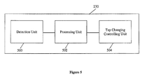
- Figure 5 shows a schematic drawing of a tap control unit used for correcting voltage imbalances at a transformer for a wind park according to an embodiment of the present invention.
- FIG. 1 illustrates a common setup of a conventional wind turbine 100.
- the wind turbine 100 is mounted on a base 102.
- the wind turbine 100 includes a tower 104 having a number of towers sections, such as tower rings.
- a wind turbine nacelle 106 is placed on top of the tower 104.
- the wind turbine rotor includes a hub 108 and at least one rotor blade 110, e.g. three rotor blades 110.
- the rotor blades 110 are connected to the hub 108 which in turn is connected to the nacelle 106 through a low speed shaft which extends out of the front of the nacelle 106.
- FIGs 2a to 2e respectively show a schematic diagram of a wind park 200a to 200e (also known as “wind farm” or a “wind power plant”) according to an embodiment of the present invention.
- the wind park 200 includes a plurality of wind turbines 100.
- wind park in the sense of the present invention may also include the case of only one wind turbine.
- the wind turbines 100 are coupled to a power grid 202 via a transformer 204 via power lines 212.
- the transformer 204 is coupled between the wind turbines 100 and the power grid 202 via power lines 212.
- the wind park further 200a comprises a tap control unit 230 coupled to both the power grid 202 and the transformer 204 via control lines 206 (may also be referred as data lines).
- the tap control unit 230 serves for detecting voltage imbalances occurring on the power grid 202 and to control the transformer 204 in a way that undesired effects of the voltage imbalances on the wind park 200 can be prevented ("voltage compensation").
- the tap control unit 230 and the transformer 204 are separate devices.
- the tap control unit 230 may also be integrated into the transformer 204.
- each wind turbine 100 may also have "its own" transformer 204 which may be integrated into the respective wind turbine 100 itself or be provided outside of the respective wind turbine 100.
- each transformer 204 is connected to a centralized tap control unit 230 which is connected to the power grid 202 and which controls the operation of the transformers 204.
- the centralized tap control unit 230 is connected to the transformers 204 and the power grid 202 via control lines 206.
- each transformer 204 may be connected to an individual tap control unit 230 which may respectively be integrated into the corresponding wind turbine 100 or provided outside of the wind turbine 100.
- Each transformer 204 may be connected to the individual tap control unit 230 via control lines 206.
- Figures 2d and 2e show examples on how the wind park 200a shown in figure 2a may be realized in detail.
- Figures 2d and 2e shows wind parks 200d and 200e including a power plant controller 205 respectively.
- the power plant controller 205 generally fulfils a plurality of control functions.
- the power plant controller 205 may collect different types of data which characterizes the current state of the wind turbines 100 in the wind parks 200d and 200e or components thereof, and in response thereto control the components in the wind park 200d, 200e (e.g. components in the wind turbines 100).
- All wind turbines 100 may communicate with the power plant controller 205 through a wind power plant network 220 coupled to the power plant controller 205 via a control line 206.
- the wind turbines 100 may send wind turbine status data to the power plant controller 205.
- the power plant controller 205 may in response control the wind turbines 100 via the wind power plant network 220.
- the signals communicated between e.g. the wind turbines 100, the power plant controller 205, etc, can include but are not limited to power output, turbine status, power reference, and turbine command.
- the power plant controller 205 may send command data like power reference data to the wind turbines 100 to control operation of wind turbines.
- a tap control unit 230 is integrated into the power plant controller 205.
- the power plant controller 205 detects voltage imbalances occurring on the power grid 202 and controls the transformer 204 via control lines 206 in a way that undesired effects of the voltage imbalances on the wind park 200 can be prevented ("voltage compensation").
- the tap control unit 230 and the power plant controller 205 may also be separate devices.
- the tap control unit 230 detects voltage imbalances occurring on the power grid 202 and controls the transformer 204 via control lines 206 in a way that undesired effects of the voltage imbalances on the wind park 200 can be prevented ("voltage compensation").
- the power plant controller 205 is coupled to the power grid 202 and to a transmission system operator (TSO) interface 207 via control lines 206.
- the power plant controller 205 may receive data or signals from the TSO interface 207.
- the TSO interface 207 may be used to transmit electrical power from power generation plants (in this case, the wind parks) to regional or local electricity distribution operators.
- the power plant controller 205 is further connected to breakers or relays 218a, 218b and to compensation devices 210 via control lines 206.
- the breakers or relays 218a, 218b can be used to disconnect power lines 212 in cases of high currents: In the case of high currents, respective control signals are communicated to the power plant controller 205 via control lines 206 which in response thereto controls the breakers or relays 218a, 218b to disconnect power lines 212.
- the wind turbines 100 are connected to breakers or relays 218a via power lines 212.
- the breakers or relays 218a are connected to breaker or relay 218b via power lines 212.
- the breaker or relay 218b is connected to the transformer 204 via a power line 212.
- the compensation devices 210 can include but are not limited to reactive power generation devices used to compensate reactive power of the wind park 200d of figure 2d and the wind park 200e of figure 2e .
- the compensation devices 210 can be a thyristor switched capacitor bank and a static Var compensator (SVC).
- the power plant controller 205 is configured to measure voltages and currents at a point 208 between the power grid 202 and the transformer 204 (point 208 may for example be the point of common coupling), in particular voltage imbalances and current imbalances occurring at point 208.
- the power plant controller 205 may also be configured to detect voltage imbalances at other points. It is assumed here that the voltages and currents on the power grid 202 usually have three phases, however it is to be understood that the present invention is not limited thereto. That is, the voltages and currents on the power grid 202 may also have more or less than three phases.
- the voltage imbalances may for example be detected by determining if the three phase voltages occurring at the point of common coupling 208 form a negative voltage sequence or a zero voltage sequence.
- the voltage imbalances may also be detected in different ways, e.g. by comparing voltage amplitudes.
- a balanced e.g. three phase voltage/current means that the three line voltages/currents are equal in RMS/peak magnitude and the respective phase angles of the voltages/currents are displaced from each other by 120° (i.e. 360°/3). Voltage imbalances occur when there is a difference between the e.g. three voltage magnitudes and/or there is a shift in the phase angle difference from 120°. If there are six phases, voltage imbalances occur when there is a difference between the six voltage magnitudes and/or there is a shift in the phase angle difference from 60° (i.e. 360°/6).
- FIGS 3a to 3c show a schematic diagram of a possible embodiment of the transformer 204.
- the transformer 204 is a tap controlled transformer.
- the transformer 204 includes a primary winding arrangement 302 coupled to the power grid 202, and a secondary winding arrangement 304 coupled to the wind turbines 100.
- the power grid 202 has at least three power lines, e.g. three power lines 306a, 306b, 306c. Each power line 306a, 306b, 306c can conduct a respective phase of a multi-phase current.
- the primary winding arrangement 302 has at least three windings, e.g. three windings 308a, 308b, 308c. Each power line 306a, 306b, 306c of the power grid 202 is coupled to the primary winding arrangement 302 via an individual tap changer 310a, 310b, 310c.
- the windings 308a, 308b, 308c of the primary winding arrangement 302 are connected in a wye like configuration.
- the windings 308a, 308b, 308c of the primary winding arrangement 302 may be connected in a delta like configuration.
- the primary winding arrangement 302 is part of a high voltage side 303 of the transformer 204.
- the primary winding arrangement 302 has three windings 308a, 308b, 308c
- the secondary winding arrangement 304 also has three windings 312a, 312b, 312c.
- the number of windings of the primary winding arrangement 302 and the secondary winding arrangement 304 may be changed accordingly.
- each of the windings 308a, 308b, 308c of the primary winding arrangement 302 is coupled to one of the phases of the multi-phase voltage.
- each phase of the multi-phase voltage may also be connected to two or more windings.
- each of the windings 308a, 308b, 308c may respectively be split up into two or more windings.
- each of the windings 312a, 312b, 312c of secondary winding arrangement 304 may respectively be split up into two or more windings.
- the windings 312a, 312b, 312c of the secondary winding arrangement 304 are connected in a delta like configuration in one embodiment.
- the windings 312a, 312b, 312c of the secondary winding arrangement 304 may be connected in a wye like configuration.
- the secondary winding arrangement 304 is part of a low voltage side 305 of the transformer 204.
- X, Y, and Z represent respective conductors of the power line 212 connected to the main transformer 204, each conductor carrying a phase of a multi phase current.
- Each winding 308a, 308b, 308c of the primary winding arrangement 302 is coupled to the respective power line 306a, 306b, 306c via an individual tap changer 310a, 310b, 310c.
- the tap changers 310a, 310b, 310c can be but are not limited to a mechanical tap changer, an electrical tap changer, and an electrical assisted tap changer.
- the tap changers 310a, 310b, 310c may be realized as on-load tap changers or as off-load tap changers.
- the tap changers 310a, 310b, 310c can be used to handle load effect and voltage regulation.
- Each tap changer 310a, 310b, 310c may have a plurality of contact points 314a, 314b, 314c (see Figure 3a ) or a contact line 316a, 316b, 316c (see Figure 3b ) connected to the primary winding arrangement 302.
- the primary winding arrangement 302 is connectable to the power lines 306a, 306b, 306c via the contact points 314a, 314b, 314c (see Figure 3a ) or the contact lines 316a, 316b, 316c (see Figure 3b ).
- Each tap changer 310a, 310b, 310c may have a sliding contact 318a, 318b, 318c for selectively contacting one of the plurality of contact points 314a, 314b, 314c (see Figure 3a ) or for continuously sliding along the contact lines 316a, 316b, 316c (see Figure 3b ).
- each tap changer 310a, 310b, 310c may have a switch 320a, 320b, 320c assigned to each contact point 314a, 314b, 314c (see Figure 3c ).
- Each switch 320a, 320b, 320c can connect one contact point 314a, 314b, 314c to the power lines 306a, 306b, 306c.
- the switches 320a, 320b, 320c can be selectively opened and closed.
- the plurality of contact points 314a, 314b, 314c for the tap changers 310a, 310b, 310c may be arranged such that each contact point 314a, 314b, 314c is spaced apart from an adjacent contact point 314a, 314b, 314c of the same winding 306a, 306b, 306c by a single turn (more generally: by the same amount of turns) of the respective windings 306a, 306b, 306c of the primary winding arrangement 302.
- the voltage change across two adjacent contact points 314a, 314b, 314c of the same winding 306a, 306b, 306c can be the voltage across a single turn (more generally: the voltage across a particular amount of turns).
- the spacing of the contact points 314a, 314b, 314c may also be an in-equidistant spacing.
- FIG. 4 shows a flowchart 400 of an embodiment of correcting voltage imbalances according to the present invention.
- voltage imbalances occurring on the power grid are detected.
- respective tap changer adjustments for the at least one tap changer needed in order to compensate influences of the detected voltage imbalances on the wind turbines are calculated.
- the at least one tap changer is adjusted based on the respective calculated tap changer adjustments.
- FIG. 5 shows an example of a tap control unit 230 according to one embodiment of the present invention.
- the tap control unit 230 comprises a detection unit 500 coupled to the power grid 202, the detection unit 500 being configured to detect voltage imbalances occurring on the power grid 202 coupled to the primary winding arrangement 303.
- the tap control unit 230 further comprises a processing unit 502 coupled to the detection unit 500, the processing unit 502 being configured to calculate respective tap changer adjustments for each tap changer 310a, 310b, 310c needed in order to compensate the detected voltage imbalances.
- the tap control unit 230 further comprises a tap changing controlling unit 504 coupled to the processing unit 502, the tap changing controlling unit 504 being configured to control a tap changer adjustment process based on the calculated tap changer adjustments. Details of how voltages imbalances may be detected and compensated are described in the following.
- the detection unit 500 measures voltages and currents from the point of common coupling 208 between the power grid 202 and the transformer 204.
- the detection unit 500 also detects voltage imbalances occurring on the power grid 202.
- the voltages imbalances may for example be detected by determining if the three phase voltages from the point of common coupling 208 form a negative voltage sequence or a zero voltage sequence.
- the voltage imbalances may also be detected by comparing the voltage amplitudes.
- the processing unit 502 calculates respective tap changer adjustments for each tap changer 310a, 310b, 310c needed in order to compensate the detected voltage imbalances.
- the tap changing controlling unit 504 controls a tap changer adjustment process based on the calculated tap changer adjustments.
- the tap changer adjustments can be calculated by various methods. Two exemplary methods which may be used are scalar compensation method and vector compensation method.
- the respective transformer nominal voltages V am , V bm and V cm are given for specific point of common coupling (PCC) 208.
- the respective measured transformer voltages V a , V b and V c are measured at the power grid side.
- the transformer voltage V a is measured from the power line 306a to a neutral point N of the primary winding arrangement 302 (as shown in Figures 3a to 3c ).
- the transformer voltage V b is measured from the power line 306b to a neutral point N of the primary winding arrangement 302 (as shown in Figures 3a to 3c ).
- the transformer voltage V c is measured from the power line 306c to a neutral point N of the primary winding arrangement 302 (as shown in Figures 3a to 3c ).
- the tap changers 310a, 310b, 310c can be adjusted based on the calculated voltage compensations ⁇ V a , ⁇ V b and ⁇ V c respectively.
- the positive sequence components and the negative sequence components can be obtained from a multi-phase voltage using some conventional algorithms.
- the respective voltage compensations for the tap changers 310a, 310b, 310c can then be calculated using the scalar compensation method described above.
- the tap changers 310a, 310b, 310c can be adjusted based on the calculated voltage compensations ⁇ V a , ⁇ V b and ⁇ V c respectively.
- each tap changer 310a, 310b, 310c can be adjusted individually.
- the electrical connections between the power grid 202 and the contact points 314a, 314b, 314c can be changed or adjusted by selectively contacting one of the plurality of contact points 314a, 314b, 314c.
- the electrical connections between the power grid 202 and the contact lines 316a, 316b, 316c can be changed or adjusted by moving the respective sliding contacts 318a, 318b, 318c along the respective contact lines 316a, 316b, 316c to a particular position.
- the electrical connections between the power grid 202 and the contact points 314a, 314b, 314c or the contact lines 316a, 316b, 316c can be changed or adjusted by selectively opening or closing the switches 320a, 320b, 320c respectively assigned to the contact points 314a, 314b, 314c or the contact lines 316a, 316b, 316c.
- the tap changers 310a, 310b, 310c shown in Figure 3a will be used as an illustration example for describing a tap changer adjustment process. It is assumed that, initially, the sliding contact 318a of the tap changer 310a for the phase A voltage (e.g. of power line 306a) was placed at the contact point 314a labelled '2a', the sliding contact 318b of the tap changer 310b for the phase B voltage (e.g. of power line 306b) was placed at the contact point 314b labelled '2b', and the sliding contact 318c of the tap changer 310c for the phase C voltage (e.g. of power line 306c) was placed at the contact point 314c labelled '2c'.
- the sliding contact 318a of the tap changer 310a for the phase A voltage e.g. of power line 306a
- the sliding contact 318b of the tap changer 310b for the phase B voltage e.g. of power line 306b
- a balanced voltage can be obtained in the secondary winding arrangement 304 by moving the sliding contact 318b of the tap changer 310b along the contact line 316b from a position labelled '2b' to a position labelled '3b'.
- phase tap control with individual tap control for each phase of a transformer has been described.
- phase tap control (three phase tap control or a tap control having less than two phases or more than three phases) without individual tap control for each phase of a transformer may be used for correcting the voltage imbalances.
- the phase tap control without individual tap control may have the same configuration as the phase tap control with individual tap control as shown in Figures 3a to 3c .
- the three tap changers 310a, 310b, 310c may be controlled simultaneously.
- a common control signal representing a calculated tap changer adjustment may be sent from the tap control unit 230 to the three tap changers 310a, 310b, 310c at the same time.
- the three tap changers 310a, 310b, 310c may be controlled individually. That is, a respective control signal representing a respective calculated tap changer adjustment may be sent from the tap control unit 230 to each of the three tap changers 310a, 310b, 310c either at the same time or at different timings.
- the respective control signal for each of the three tap changers 310a, 310b, 310c may represent a same calculated tap changer adjustment or a different calculated tap changer adjustment.
- individual three phase tap control Compared to a three phase tap control without individual tap control, individual three phase tap control enables a better protection of wind turbines of a wind park: without individual tap control, the three phase voltages can only be adjusted simultaneously within a certain range, i.e. a fully balanced three phase voltage might not be achieved.
- some tap changers (e.g. at least two tap changers) of a phase tap control may be controlled simultaneously while the remaining tap changers (e.g. at least one tap changer) of the phase tap control may be controlled individually.
- two tap changers (e.g. tap changers 310b, 310c) of a corresponding three phase tap control may be controlled simultaneously while one tap changer (e.g. tap changer 310a) may be controlled individually. That is, a common control signal representing a calculated tap changer adjustment may be sent from the tap control unit 230 to the tap changers 310b, 310c at the same time.
- the tap changers 310b, 310c may be adjusted simultaneously based on one calculated tap changer adjustment.
- a further control signal representing a further calculated tap changer adjustment may be sent from the tap control unit 230 to the tap changer 310a.
- the tap changer 310a may be adjusted based on the further calculated tap changer adjustment.
- the control signal for the tap changer 310a and the control signal for the tap changers 310b, 310c may represent a same calculated tap changer adjustment or a different calculated tap changer adjustment respectively. That is, the further calculated tap changer adjustment for the tap changer 310a and the calculated tap changer adjustment for the tap changers 310b, 310c may be the same in one embodiment.
- the further calculated tap changer adjustment for the tap changer 310a and the calculated tap changer adjustment for the tap changers 310b, 310c may be different in another embodiment.
- the control signal for the tap changer 310a and the control signal for the tap changers 310b, 310c may be sent from the tap control unit 230 at the same time or at different timings.
- a first set of tap changers can be controlled using a first control signal representing a calculated tap changer adjustment
- a second set of tap changers can be controlled using a further control signal representing a further calculated tap changer adjustment
- the remaining one or more tap changers, if any, can be controlled individually using respective control signals representing respective calculated tap changer adjustments.
- the first set of tap changers may have one tap changer, which can be adjusted individually based on the calculated tap changer adjustment. In cases where the first set of tap changers have more than one tap changers, the tap changers can be adjusted simultaneously based on one calculated tap changer adjustment.
- the second set of tap changers may have one tap changer, which can be adjusted individually based on the further calculated tap changer adjustment.
- the tap changers can be adjusted simultaneously based on the further calculated tap changer adjustment.
- the tap changers can be grouped in various different ways (e.g. into different numbers of sets of tap changers) for adjustment by the respective calculated tap changer adjustments in other embodiments.
Landscapes
- Engineering & Computer Science (AREA)
- Power Engineering (AREA)
- Supply And Distribution Of Alternating Current (AREA)
Applications Claiming Priority (2)
| Application Number | Priority Date | Filing Date | Title |
|---|---|---|---|
| US17016809P | 2009-04-17 | 2009-04-17 | |
| DKPA200900501 | 2009-04-17 |
Publications (3)
| Publication Number | Publication Date |
|---|---|
| EP2242159A2 true EP2242159A2 (de) | 2010-10-20 |
| EP2242159A3 EP2242159A3 (de) | 2012-05-30 |
| EP2242159B1 EP2242159B1 (de) | 2016-04-13 |
Family
ID=42537473
Family Applications (1)
| Application Number | Title | Priority Date | Filing Date |
|---|---|---|---|
| EP10160003.9A Active EP2242159B1 (de) | 2009-04-17 | 2010-04-15 | Windpark, Verfahren zum Korrigieren von Spannungsschwankungen und Windturbine |
Country Status (4)
| Country | Link |
|---|---|
| US (1) | US8698334B2 (de) |
| EP (1) | EP2242159B1 (de) |
| CN (1) | CN101867194A (de) |
| ES (1) | ES2571222T3 (de) |
Cited By (5)
| Publication number | Priority date | Publication date | Assignee | Title |
|---|---|---|---|---|
| WO2013013656A3 (de) * | 2011-07-22 | 2013-03-21 | ct.e Controltechnology Engineering GmbH | Verfahren zur adaptiven regelung der versorgungsspannung in ortsnetzen |
| EP2551984B1 (de) | 2011-07-29 | 2018-05-23 | General Electric Company | Kraftwerksteuerungssystem und Verfahren zum Beeinflussen von Hochspannungsmerkmalen |
| EP3591785A1 (de) * | 2018-07-04 | 2020-01-08 | Vestas Wind Systems A/S | Windturbine mit einem laststufenschalter, der mit dynamischer fehlerstromeinspeisung |
| EP3742251A1 (de) * | 2019-05-24 | 2020-11-25 | Siemens Gamesa Renewable Energy Innovation & Technology, S.L. | Windturbinentransformatorsteuerung |
| EP4189797B1 (de) * | 2020-07-31 | 2024-10-23 | Fraunhofer-Gesellschaft zur Förderung der angewandten Forschung e.V. | Elektrisches energiesystem |
Families Citing this family (22)
| Publication number | Priority date | Publication date | Assignee | Title |
|---|---|---|---|---|
| JP4575272B2 (ja) * | 2005-10-27 | 2010-11-04 | 株式会社日立製作所 | 分散型電源システム及び系統安定化方法 |
| US8405251B2 (en) * | 2010-04-20 | 2013-03-26 | General Electric Company | Method and apparatus for reduction of harmonics in a power supply |
| EP2485358B2 (de) * | 2011-02-07 | 2021-12-22 | Siemens Gamesa Renewable Energy A/S | System und Verfahren zur Abschwächung eines elektrischen Ungleichgewichts eines Dreiphasenstroms an einem gemeinsamen Anschlusspunkt zwischen einem Windpark und einem Stromnetz |
| WO2012110087A1 (en) * | 2011-02-16 | 2012-08-23 | Abb Research Ltd | Method and arrangement for detecting an internal failure in h-bridge connected capacitor bank |
| ES2638899T3 (es) * | 2011-04-27 | 2017-10-24 | Siemens Aktiengesellschaft | Procedimiento y distribución para el suministro de energía eléctrica desde una central eólica a una red de tensión alterna |
| CN102354998B (zh) * | 2011-09-28 | 2013-11-06 | 东北大学 | 基于三维区图策略控制变压器运行的方法 |
| US8957649B2 (en) | 2012-03-01 | 2015-02-17 | Cooper Technologies Company | Manual multi-phase voltage control |
| CN103364723B (zh) * | 2012-04-05 | 2015-12-16 | 北京光耀能源技术股份有限公司 | 基于电压电流平衡性的风力发电机运行状态分析方法 |
| DK2711543T3 (en) * | 2012-09-21 | 2016-11-28 | Siemens Ag | Operation of a wind turbine and a wind farm in different netstyrker |
| US8872366B2 (en) * | 2013-01-31 | 2014-10-28 | APR Energy, LLC | Scalable portable modular power plant |
| EP2955808B1 (de) * | 2014-06-13 | 2018-08-08 | Nordex Energy GmbH | Verfahren zur Regelung einer Windenergieanlage während eines asymmetrischen Netzfehlers |
| US9780709B2 (en) | 2014-09-03 | 2017-10-03 | General Electric Company | System and method for optimizing wind turbine operation |
| CN104201678A (zh) * | 2014-09-25 | 2014-12-10 | 张慧慧 | 智能电网远程综合控制装置 |
| US9828971B2 (en) * | 2014-11-20 | 2017-11-28 | General Electric Company | System and method for optimizing wind turbine operation |
| DE102014119158A1 (de) * | 2014-12-19 | 2016-06-23 | Maschinenfabrik Reinhausen Gmbh | Selektives Parallellaufverfahren für Mess-/Steuergeräte |
| WO2016177376A1 (en) * | 2015-05-06 | 2016-11-10 | Vestas Wind Systems A/S | Wind turbine power generation system |
| US11336098B2 (en) * | 2016-06-13 | 2022-05-17 | Vestas Wind Systems A/S | Interconnection of multiple renewable energy power plants |
| US10634121B2 (en) | 2017-06-15 | 2020-04-28 | General Electric Company | Variable rated speed control in partial load operation of a wind turbine |
| CN108183641B (zh) * | 2017-12-31 | 2019-10-08 | 中国能源建设集团华东电力试验研究院有限公司 | 6kV进线电压平衡系统 |
| EP3644469A1 (de) * | 2018-10-22 | 2020-04-29 | Siemens Gamesa Renewable Energy Innovation & Technology, S.L. | Erkennungsvorrichtung und verfahren zum erkennen eines fehlers in einem transformator einer windturbine |
| US12237687B2 (en) | 2020-01-21 | 2025-02-25 | Vestas Wind Systems A/S | Wind turbine power generation comprising an AC-DC-AC converter and a transformer with a tap changer |
| EP4592698A1 (de) * | 2024-01-29 | 2025-07-30 | Nordex Energy Spain, S.A.U. | Verfahren zur identifizierung eines defekts in einer elektrischen komponente einer energieanlage, generatoreinheit, energieanlage, computerimplementiertes verfahren und computerprogrammprodukt |
Family Cites Families (29)
| Publication number | Priority date | Publication date | Assignee | Title |
|---|---|---|---|---|
| US2525489A (en) * | 1948-11-19 | 1950-10-10 | Westinghouse Electric Corp | Control system |
| US2546725A (en) * | 1949-10-29 | 1951-03-27 | Gen Electric | Phase balancing apparatus |
| CA611971A (en) * | 1957-06-24 | 1961-01-03 | Westinghouse Electric Corporation | Tap-changing equipment |
| US3153132A (en) * | 1960-09-08 | 1964-10-13 | Rockwell Standard Co | Induction heating apparatus |
| US3448286A (en) * | 1963-10-31 | 1969-06-03 | Asea Ab | Balancing of harmonics at converter stations in asymmetrical working |
| US3530362A (en) * | 1968-03-04 | 1970-09-22 | Alexei Nikolaevich Filimonov | Converter substation for direct current power transmission |
| US3536817A (en) * | 1968-05-22 | 1970-10-27 | Barbara Carroll | Electric furnace regulation system |
| SE341958B (de) * | 1969-11-12 | 1972-01-17 | Asea Ab | |
| SU617797A1 (ru) | 1974-05-05 | 1978-07-30 | Belousov Viktor S | Устройство дл симметировани напр жени в трехфазных сет х с глухим заземлением нейтрали |
| US6108226A (en) * | 1996-06-24 | 2000-08-22 | Ghosh; Ramit | Voltage selection apparatus and methods |
| JPH1198690A (ja) | 1997-09-25 | 1999-04-09 | Aichi Electric Co Ltd | 自動電圧不平衡是正装置 |
| US6946750B2 (en) * | 2000-08-14 | 2005-09-20 | Aloys Wobben | Wind power plant having a power generation redundancy system |
| BR0212820A (pt) * | 2001-09-28 | 2004-10-13 | Aloys Wobben | Processo para operação de um parque eólico, parque eólico, e, instalação de energia eólica |
| JP2004088929A (ja) | 2002-08-27 | 2004-03-18 | Toshiba Corp | 電圧不平衡低減装置 |
| ES2402150T3 (es) * | 2003-04-08 | 2013-04-29 | Converteam Gmbh | Turbina eólica para la producción de energía eléctrica y procedimiento de funcionamiento |
| DE10327344A1 (de) * | 2003-06-16 | 2005-01-27 | Repower Systems Ag | Windenergieanlage |
| US6906476B1 (en) * | 2003-07-25 | 2005-06-14 | Asp Corporation | Power control system for reducing power to lighting systems |
| GB2410386A (en) | 2004-01-22 | 2005-07-27 | Areva T & D Uk Ltd | Controlling reactive power output |
| JP2006014445A (ja) | 2004-06-24 | 2006-01-12 | Hitachi Ltd | 配電線電圧変動補償装置 |
| CN1588747A (zh) | 2004-08-27 | 2005-03-02 | 南宁欧顶电气有限责任公司 | 三相稳压调控装置及其控制方法 |
| JP2008526179A (ja) * | 2004-12-28 | 2008-07-17 | ヴェスタス,ウィンド,システムズ エー/エス | 電気事業配電網に接続された風力タービンの制御方法 |
| ES2263375B1 (es) * | 2005-04-15 | 2007-11-16 | GAMESA INNOVATION & TECHNOLOGY, S.L. | Dispositivo generador de huecos de tension. |
| DK1880459T3 (da) * | 2005-05-13 | 2013-11-04 | Siemens Ag | Effektstyresystem til vindmøllepark |
| US7239036B2 (en) * | 2005-07-29 | 2007-07-03 | General Electric Company | System and method for power control in wind turbines |
| MX2008016209A (es) * | 2006-07-03 | 2009-02-17 | Vestas Wind Sys As | Sistema para probar turbinas eolicas. |
| US7629705B2 (en) * | 2006-10-20 | 2009-12-08 | General Electric Company | Method and apparatus for operating electrical machines |
| US7642666B2 (en) | 2006-11-02 | 2010-01-05 | Hitachi, Ltd. | Wind power generation apparatus, wind power generation system and power system control apparatus |
| DE102007017870B4 (de) | 2007-04-13 | 2022-03-31 | Senvion Gmbh | Verfahren zum Betreiben einer Windenergieanlage bei Überspannungen im Netz |
| US8058753B2 (en) * | 2008-10-31 | 2011-11-15 | General Electric Company | Wide area transmission control of windfarms |
-
2010
- 2010-04-15 ES ES10160003T patent/ES2571222T3/es active Active
- 2010-04-15 EP EP10160003.9A patent/EP2242159B1/de active Active
- 2010-04-16 US US12/761,864 patent/US8698334B2/en active Active
- 2010-04-16 CN CN201010163925A patent/CN101867194A/zh active Pending
Non-Patent Citations (1)
| Title |
|---|
| None |
Cited By (8)
| Publication number | Priority date | Publication date | Assignee | Title |
|---|---|---|---|---|
| WO2013013656A3 (de) * | 2011-07-22 | 2013-03-21 | ct.e Controltechnology Engineering GmbH | Verfahren zur adaptiven regelung der versorgungsspannung in ortsnetzen |
| EP2551984B1 (de) | 2011-07-29 | 2018-05-23 | General Electric Company | Kraftwerksteuerungssystem und Verfahren zum Beeinflussen von Hochspannungsmerkmalen |
| EP3591785A1 (de) * | 2018-07-04 | 2020-01-08 | Vestas Wind Systems A/S | Windturbine mit einem laststufenschalter, der mit dynamischer fehlerstromeinspeisung |
| US10914288B2 (en) | 2018-07-04 | 2021-02-09 | Vestas Wind Systems A/S | Wind turbine with an on-load tap changer configured with dynamic fault current injection |
| EP3742251A1 (de) * | 2019-05-24 | 2020-11-25 | Siemens Gamesa Renewable Energy Innovation & Technology, S.L. | Windturbinentransformatorsteuerung |
| WO2020239425A1 (en) | 2019-05-24 | 2020-12-03 | Siemens Gamesa Renewable Energy Innovation & Technology S.L. | Wind turbine transformer control |
| US12346140B2 (en) | 2019-05-24 | 2025-07-01 | Siemens Gamesa Renewable Energy Innovation & Technology S.L. | Wind turbine transformer control |
| EP4189797B1 (de) * | 2020-07-31 | 2024-10-23 | Fraunhofer-Gesellschaft zur Förderung der angewandten Forschung e.V. | Elektrisches energiesystem |
Also Published As
| Publication number | Publication date |
|---|---|
| EP2242159B1 (de) | 2016-04-13 |
| EP2242159A3 (de) | 2012-05-30 |
| US8698334B2 (en) | 2014-04-15 |
| CN101867194A (zh) | 2010-10-20 |
| ES2571222T3 (es) | 2016-05-24 |
| US20100264666A1 (en) | 2010-10-21 |
Similar Documents
| Publication | Publication Date | Title |
|---|---|---|
| EP2242159B1 (de) | Windpark, Verfahren zum Korrigieren von Spannungsschwankungen und Windturbine | |
| EP2481139B1 (de) | Verfahren zur steuerung eines stromumrichters in einem windturbinengenerator | |
| EP2394356B1 (de) | Hybrid-verteilungstransformator mit wechselstrom- und gleichstrom-leistungsfähigkeiten | |
| Boutsika et al. | Short-circuit calculations in networks with distributed generation | |
| Eriksson | Operational experience of HVDC Light/sup TM | |
| EP2528184B1 (de) | Verfahren und Vorrichtung zur Steuerung eines DC-Übertragungslinks | |
| US8310105B2 (en) | Centralized islanding protection for distributed renewable energy generators | |
| CN101345464B (zh) | 一种采用交直交变流器调速的双馈电动机及其启动控制方法 | |
| US10581247B1 (en) | System and method for reactive power control of wind turbines in a wind farm supported with auxiliary reactive power compensation | |
| AU2011263709B2 (en) | Method for feeding electrical power into a three-phase AC voltage system | |
| EP3756257B1 (de) | Gleichstromsteuerung bei vsc-basierten hvdc-wandlern | |
| EP3806318B1 (de) | Elektrische stromerzeugungsvorrichtung mit variabler geschwindigkeit | |
| CN114447972A (zh) | 基于既有牵引变压器的贯通柔性牵引变电所及其保护配置方法 | |
| US20130027992A1 (en) | Method for inputting power and power input system | |
| EP3172825B1 (de) | Spannungsquellenwandler | |
| US20120044727A1 (en) | Method and circuit arrangement for supplying a multiphase electrical network | |
| CN116298582A (zh) | 用于新能源送出系统的距离保护适应性分析方法及装置 | |
| Ramamurthy et al. | Mitigation of motor starting voltage sags using distribution-class statcom | |
| Mati et al. | Impact of STATCOM on generator positive-offset mho element loss of excitation protection | |
| US10288040B2 (en) | Current limit calculation for wind turbine control | |
| Wang | The protection of transmission networks containing ac and dc circuits | |
| CN216215907U (zh) | 一种电力系统合环相位校正装置 | |
| Nikolaev et al. | Sustainability of High-Power Frequency Converters with Active Rectifiers Connected in Parallel with “EAF-SVC” Complex | |
| CN105356737B (zh) | 高压变频器输出电压自均衡方法 | |
| Dasgupta et al. | A Control Strategy for a VSC HVDC System in steady state response |
Legal Events
| Date | Code | Title | Description |
|---|---|---|---|
| PUAI | Public reference made under article 153(3) epc to a published international application that has entered the european phase |
Free format text: ORIGINAL CODE: 0009012 |
|
| AK | Designated contracting states |
Kind code of ref document: A2 Designated state(s): AT BE BG CH CY CZ DE DK EE ES FI FR GB GR HR HU IE IS IT LI LT LU LV MC MK MT NL NO PL PT RO SE SI SK SM TR |
|
| AX | Request for extension of the european patent |
Extension state: AL BA ME RS |
|
| RAP1 | Party data changed (applicant data changed or rights of an application transferred) |
Owner name: VESTAS WIND SYSTEMS A/S |
|
| PUAL | Search report despatched |
Free format text: ORIGINAL CODE: 0009013 |
|
| RIC1 | Information provided on ipc code assigned before grant |
Ipc: H02J 3/26 20060101ALI20120420BHEP Ipc: H02J 3/12 20060101ALI20120420BHEP Ipc: H02J 3/00 20060101AFI20120420BHEP Ipc: H01H 9/00 20060101ALI20120420BHEP |
|
| AK | Designated contracting states |
Kind code of ref document: A3 Designated state(s): AT BE BG CH CY CZ DE DK EE ES FI FR GB GR HR HU IE IS IT LI LT LU LV MC MK MT NL NO PL PT RO SE SI SK SM TR |
|
| AX | Request for extension of the european patent |
Extension state: AL BA ME RS |
|
| 17P | Request for examination filed |
Effective date: 20121130 |
|
| 17Q | First examination report despatched |
Effective date: 20140521 |
|
| RAP1 | Party data changed (applicant data changed or rights of an application transferred) |
Owner name: VESTAS WIND SYSTEMS A/S |
|
| REG | Reference to a national code |
Ref country code: DE Ref legal event code: R079 Ref document number: 602010032181 Country of ref document: DE Free format text: PREVIOUS MAIN CLASS: H02J0003000000 Ipc: H02J0003180000 |
|
| GRAP | Despatch of communication of intention to grant a patent |
Free format text: ORIGINAL CODE: EPIDOSNIGR1 |
|
| INTG | Intention to grant announced |
Effective date: 20151023 |
|
| RIC1 | Information provided on ipc code assigned before grant |
Ipc: H02J 3/38 20060101ALI20151013BHEP Ipc: H02J 3/26 20060101ALI20151013BHEP Ipc: H02J 3/18 20060101AFI20151013BHEP |
|
| GRAS | Grant fee paid |
Free format text: ORIGINAL CODE: EPIDOSNIGR3 |
|
| GRAA | (expected) grant |
Free format text: ORIGINAL CODE: 0009210 |
|
| INTG | Intention to grant announced |
Effective date: 20160303 |
|
| AK | Designated contracting states |
Kind code of ref document: B1 Designated state(s): AT BE BG CH CY CZ DE DK EE ES FI FR GB GR HR HU IE IS IT LI LT LU LV MC MK MT NL NO PL PT RO SE SI SK SM TR |
|
| REG | Reference to a national code |
Ref country code: GB Ref legal event code: FG4D |
|
| REG | Reference to a national code |
Ref country code: AT Ref legal event code: REF Ref document number: 791050 Country of ref document: AT Kind code of ref document: T Effective date: 20160415 Ref country code: CH Ref legal event code: EP |
|
| REG | Reference to a national code |
Ref country code: IE Ref legal event code: FG4D |
|
| REG | Reference to a national code |
Ref country code: ES Ref legal event code: FG2A Ref document number: 2571222 Country of ref document: ES Kind code of ref document: T3 Effective date: 20160524 |
|
| REG | Reference to a national code |
Ref country code: FR Ref legal event code: PLFP Year of fee payment: 7 |
|
| REG | Reference to a national code |
Ref country code: DE Ref legal event code: R096 Ref document number: 602010032181 Country of ref document: DE |
|
| REG | Reference to a national code |
Ref country code: LT Ref legal event code: MG4D |
|
| PG25 | Lapsed in a contracting state [announced via postgrant information from national office to epo] |
Ref country code: BE Free format text: LAPSE BECAUSE OF NON-PAYMENT OF DUE FEES Effective date: 20160430 |
|
| REG | Reference to a national code |
Ref country code: AT Ref legal event code: MK05 Ref document number: 791050 Country of ref document: AT Kind code of ref document: T Effective date: 20160413 |
|
| REG | Reference to a national code |
Ref country code: NL Ref legal event code: MP Effective date: 20160413 |
|
| PG25 | Lapsed in a contracting state [announced via postgrant information from national office to epo] |
Ref country code: NL Free format text: LAPSE BECAUSE OF FAILURE TO SUBMIT A TRANSLATION OF THE DESCRIPTION OR TO PAY THE FEE WITHIN THE PRESCRIBED TIME-LIMIT Effective date: 20160413 Ref country code: PL Free format text: LAPSE BECAUSE OF FAILURE TO SUBMIT A TRANSLATION OF THE DESCRIPTION OR TO PAY THE FEE WITHIN THE PRESCRIBED TIME-LIMIT Effective date: 20160413 Ref country code: LT Free format text: LAPSE BECAUSE OF FAILURE TO SUBMIT A TRANSLATION OF THE DESCRIPTION OR TO PAY THE FEE WITHIN THE PRESCRIBED TIME-LIMIT Effective date: 20160413 Ref country code: NO Free format text: LAPSE BECAUSE OF FAILURE TO SUBMIT A TRANSLATION OF THE DESCRIPTION OR TO PAY THE FEE WITHIN THE PRESCRIBED TIME-LIMIT Effective date: 20160713 Ref country code: FI Free format text: LAPSE BECAUSE OF FAILURE TO SUBMIT A TRANSLATION OF THE DESCRIPTION OR TO PAY THE FEE WITHIN THE PRESCRIBED TIME-LIMIT Effective date: 20160413 |
|
| PG25 | Lapsed in a contracting state [announced via postgrant information from national office to epo] |
Ref country code: GR Free format text: LAPSE BECAUSE OF FAILURE TO SUBMIT A TRANSLATION OF THE DESCRIPTION OR TO PAY THE FEE WITHIN THE PRESCRIBED TIME-LIMIT Effective date: 20160714 Ref country code: PT Free format text: LAPSE BECAUSE OF FAILURE TO SUBMIT A TRANSLATION OF THE DESCRIPTION OR TO PAY THE FEE WITHIN THE PRESCRIBED TIME-LIMIT Effective date: 20160816 Ref country code: LV Free format text: LAPSE BECAUSE OF FAILURE TO SUBMIT A TRANSLATION OF THE DESCRIPTION OR TO PAY THE FEE WITHIN THE PRESCRIBED TIME-LIMIT Effective date: 20160413 Ref country code: AT Free format text: LAPSE BECAUSE OF FAILURE TO SUBMIT A TRANSLATION OF THE DESCRIPTION OR TO PAY THE FEE WITHIN THE PRESCRIBED TIME-LIMIT Effective date: 20160413 Ref country code: HR Free format text: LAPSE BECAUSE OF FAILURE TO SUBMIT A TRANSLATION OF THE DESCRIPTION OR TO PAY THE FEE WITHIN THE PRESCRIBED TIME-LIMIT Effective date: 20160413 Ref country code: SE Free format text: LAPSE BECAUSE OF FAILURE TO SUBMIT A TRANSLATION OF THE DESCRIPTION OR TO PAY THE FEE WITHIN THE PRESCRIBED TIME-LIMIT Effective date: 20160413 |
|
| REG | Reference to a national code |
Ref country code: CH Ref legal event code: PL |
|
| PG25 | Lapsed in a contracting state [announced via postgrant information from national office to epo] |
Ref country code: IT Free format text: LAPSE BECAUSE OF FAILURE TO SUBMIT A TRANSLATION OF THE DESCRIPTION OR TO PAY THE FEE WITHIN THE PRESCRIBED TIME-LIMIT Effective date: 20160413 Ref country code: BE Free format text: LAPSE BECAUSE OF FAILURE TO SUBMIT A TRANSLATION OF THE DESCRIPTION OR TO PAY THE FEE WITHIN THE PRESCRIBED TIME-LIMIT Effective date: 20160413 |
|
| REG | Reference to a national code |
Ref country code: DE Ref legal event code: R097 Ref document number: 602010032181 Country of ref document: DE |
|
| REG | Reference to a national code |
Ref country code: IE Ref legal event code: MM4A |
|
| PG25 | Lapsed in a contracting state [announced via postgrant information from national office to epo] |
Ref country code: CZ Free format text: LAPSE BECAUSE OF FAILURE TO SUBMIT A TRANSLATION OF THE DESCRIPTION OR TO PAY THE FEE WITHIN THE PRESCRIBED TIME-LIMIT Effective date: 20160413 Ref country code: DK Free format text: LAPSE BECAUSE OF FAILURE TO SUBMIT A TRANSLATION OF THE DESCRIPTION OR TO PAY THE FEE WITHIN THE PRESCRIBED TIME-LIMIT Effective date: 20160413 Ref country code: CH Free format text: LAPSE BECAUSE OF NON-PAYMENT OF DUE FEES Effective date: 20160430 Ref country code: SK Free format text: LAPSE BECAUSE OF FAILURE TO SUBMIT A TRANSLATION OF THE DESCRIPTION OR TO PAY THE FEE WITHIN THE PRESCRIBED TIME-LIMIT Effective date: 20160413 Ref country code: LI Free format text: LAPSE BECAUSE OF NON-PAYMENT OF DUE FEES Effective date: 20160430 Ref country code: RO Free format text: LAPSE BECAUSE OF FAILURE TO SUBMIT A TRANSLATION OF THE DESCRIPTION OR TO PAY THE FEE WITHIN THE PRESCRIBED TIME-LIMIT Effective date: 20160413 Ref country code: MC Free format text: LAPSE BECAUSE OF FAILURE TO SUBMIT A TRANSLATION OF THE DESCRIPTION OR TO PAY THE FEE WITHIN THE PRESCRIBED TIME-LIMIT Effective date: 20160413 Ref country code: EE Free format text: LAPSE BECAUSE OF FAILURE TO SUBMIT A TRANSLATION OF THE DESCRIPTION OR TO PAY THE FEE WITHIN THE PRESCRIBED TIME-LIMIT Effective date: 20160413 |
|
| PLBE | No opposition filed within time limit |
Free format text: ORIGINAL CODE: 0009261 |
|
| STAA | Information on the status of an ep patent application or granted ep patent |
Free format text: STATUS: NO OPPOSITION FILED WITHIN TIME LIMIT |
|
| PG25 | Lapsed in a contracting state [announced via postgrant information from national office to epo] |
Ref country code: SM Free format text: LAPSE BECAUSE OF FAILURE TO SUBMIT A TRANSLATION OF THE DESCRIPTION OR TO PAY THE FEE WITHIN THE PRESCRIBED TIME-LIMIT Effective date: 20160413 |
|
| 26N | No opposition filed |
Effective date: 20170116 |
|
| REG | Reference to a national code |
Ref country code: FR Ref legal event code: PLFP Year of fee payment: 8 |
|
| PG25 | Lapsed in a contracting state [announced via postgrant information from national office to epo] |
Ref country code: SI Free format text: LAPSE BECAUSE OF FAILURE TO SUBMIT A TRANSLATION OF THE DESCRIPTION OR TO PAY THE FEE WITHIN THE PRESCRIBED TIME-LIMIT Effective date: 20160413 Ref country code: IE Free format text: LAPSE BECAUSE OF NON-PAYMENT OF DUE FEES Effective date: 20160415 |
|
| REG | Reference to a national code |
Ref country code: FR Ref legal event code: PLFP Year of fee payment: 9 |
|
| PG25 | Lapsed in a contracting state [announced via postgrant information from national office to epo] |
Ref country code: CY Free format text: LAPSE BECAUSE OF FAILURE TO SUBMIT A TRANSLATION OF THE DESCRIPTION OR TO PAY THE FEE WITHIN THE PRESCRIBED TIME-LIMIT Effective date: 20160413 Ref country code: HU Free format text: LAPSE BECAUSE OF FAILURE TO SUBMIT A TRANSLATION OF THE DESCRIPTION OR TO PAY THE FEE WITHIN THE PRESCRIBED TIME-LIMIT; INVALID AB INITIO Effective date: 20100415 |
|
| PG25 | Lapsed in a contracting state [announced via postgrant information from national office to epo] |
Ref country code: MT Free format text: LAPSE BECAUSE OF NON-PAYMENT OF DUE FEES Effective date: 20160430 Ref country code: TR Free format text: LAPSE BECAUSE OF FAILURE TO SUBMIT A TRANSLATION OF THE DESCRIPTION OR TO PAY THE FEE WITHIN THE PRESCRIBED TIME-LIMIT Effective date: 20160413 Ref country code: IS Free format text: LAPSE BECAUSE OF FAILURE TO SUBMIT A TRANSLATION OF THE DESCRIPTION OR TO PAY THE FEE WITHIN THE PRESCRIBED TIME-LIMIT Effective date: 20160413 Ref country code: MK Free format text: LAPSE BECAUSE OF FAILURE TO SUBMIT A TRANSLATION OF THE DESCRIPTION OR TO PAY THE FEE WITHIN THE PRESCRIBED TIME-LIMIT Effective date: 20160413 Ref country code: LU Free format text: LAPSE BECAUSE OF NON-PAYMENT OF DUE FEES Effective date: 20160415 |
|
| PG25 | Lapsed in a contracting state [announced via postgrant information from national office to epo] |
Ref country code: BG Free format text: LAPSE BECAUSE OF FAILURE TO SUBMIT A TRANSLATION OF THE DESCRIPTION OR TO PAY THE FEE WITHIN THE PRESCRIBED TIME-LIMIT Effective date: 20160413 |
|
| PGFP | Annual fee paid to national office [announced via postgrant information from national office to epo] |
Ref country code: DE Payment date: 20250428 Year of fee payment: 16 |
|
| PGFP | Annual fee paid to national office [announced via postgrant information from national office to epo] |
Ref country code: ES Payment date: 20250513 Year of fee payment: 16 Ref country code: GB Payment date: 20250422 Year of fee payment: 16 |
|
| PGFP | Annual fee paid to national office [announced via postgrant information from national office to epo] |
Ref country code: FR Payment date: 20250424 Year of fee payment: 16 |